

什么是用于管道生产的单螺杆挤出机
您可能已经看过几十篇关于塑料挤出机的通用讲解文章。它们大多老生常谈,泛泛而谈,却从未真正阐述生产管道时哪些因素至关重要。本文则另辟蹊径。文中所有细节都围绕管道制造展开——螺杆几何形状的选择、料筒配置以及直接影响成品壁厚、同心度和表面光洁度的工艺参数。
定义管道制造中的单螺杆挤出机
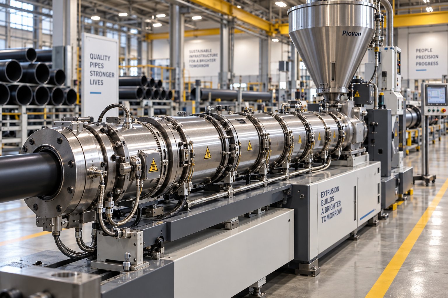
单螺杆挤出机是一种热塑性塑料加工机械,它利用加热料筒内的一根旋转螺杆,在受控压力下熔化、均质化聚合物材料,并将其通过管模挤出。
这个定义听起来很简单,但其背后的工程原理却远非如此。一台专为管材设计的单螺杆挤出机必须在数小时甚至数天的连续运行中保持熔体压力的稳定。即使是微小的波动也会导致管壁厚度的变化或管材形状的偏差,从而超出尺寸公差范围。螺杆、料筒和驱动系统协同工作,将聚合物原料颗粒或粉末转化为均匀的熔体流,并通过模头形成中空的圆形截面管材。
聚氯乙烯(PVC)、高密度聚乙烯(HDPE)和聚丙烯-再生聚合物(PP-R)占全球热塑性管道产量的绝大部分,而单螺杆挤出系统可加工这三种材料。其机械结构简单,加上数十年来久经考验的现场性能,使其成为从住宅管道到大口径市政供水干管等各种应用场景下不可或缺的塑料挤出主力设备。
为什么管道生产商选择单螺杆技术
在比较各种连续管道挤出方案时,单螺杆设计始终具有一些优势:
- 更低的资本成本——与双螺杆系统相比,更简单的机械结构意味着前期投资要少得多。
- 优异的熔体稳定性——连续拖曳流输送机制可产生长管道运行所需的稳定压力分布。
- 维护更简单——更少的活动部件和简单的螺杆和滚筒组件减少了停机时间和备件库存。
- 适用于各种主流管道聚合物——从热敏性 PVC 到高通量 HDPE,每种主流管道树脂都有专门设计的螺杆和料筒配置。
These strengths explain why single screw technology remains the dominant platform in pipe plants around the globe. But choosing the right extruder goes far beyond picking a brand or a tonnage rating. The real performance differences hide inside the screw geometry, the barrel design, and how those elements are matched to a specific pipe material - details that most equipment suppliers gloss over. The sections ahead unpack each of those details, starting with the three functional zones inside the barrel and how each one directly shapes your pipe quality.
The Three Functional Zones That Determine Pipe Quality
Every screw extruder barrel can be split into three distinct working regions - feed, compression, and metering. You will find that breakdown in any plastics textbook. What you will not find is an explanation of how each zone directly controls the pipe-specific quality metrics you care about most: wall thickness consistency, concentricity, and surface finish. That is the gap this section fills.
The three zones are created by a single extruder screw whose channel depth changes along its length. Each zone subjects the polymer to a different combination of pressure, temperature, and shear. Get the balance right across all three, and you produce pipe that meets dimensional tolerances run after run. Get it wrong in even one zone, and defects cascade all the way to the finished product.
Feed Zone and Its Role in Consistent Pipe Output
Imagine pouring a steady stream of polymer pellets or powder into the feed hopper. Gravity carries the material down into the barrel, where the screw flights pick it up and begin pushing it forward. At this stage the polymer is still solid - no melting has occurred. The channel depth in the feed zone is at its deepest, giving the screw maximum volume to grab and convey incoming material.
Why does this matter for pipe? Because inconsistent solids conveying in the feed zone shows up downstream as pressure surges at the die, which directly causes variations in pipe wall thickness. If the feed rate drops for even a few seconds, you will notice a thin spot in the wall; if it surges, the wall thickens and your haul-off speed falls out of sync. Consistent pipe starts with consistent feeding - period.
One critical technical distinction separates polyolefin pipe extrusion from PVC pipe extrusion right here in the feed zone. HDPE and PP pipe lines almost always use grooved feed barrels, where longitudinal or helical grooves are machined into the barrel bore in the feed section. These grooves grip the solid pellets mechanically, generating higher friction between the polymer and the barrel wall. The result is dramatically improved solids conveying and higher throughput at lower screw speeds. Case studies comparing grooved and smooth bore designs on HDPE have demonstrated that groove feed extruders achieve lower melt temperatures and reduced energy consumption at the same output rate - advantages that translate directly into tighter pipe dimensions and lower operating cost.
PVC pipe, by contrast, is typically processed on smooth bore barrels. PVC's powder-based dry blends and thermal sensitivity make grooved feed sections unnecessary and potentially problematic. Smooth bore designs rely on viscous drag between the barrel surface and the polymer bed, which suits PVC's processing characteristics well. Choosing the wrong feed section design for your pipe resin can undermine every other optimization you make downstream.
Compression Zone and Melt Homogeneity for Pipe
As the polymer advances past the feed section, the screw channel depth begins to decrease. This is the compression - or transition - zone, and it is where the real transformation happens. The shrinking channel forces the solid polymer bed against the heated barrel wall, generating intense shear and frictional heat. Solid particles compact, begin to melt, and gradually merge into a continuous melt pool.
For pipe applications, what happens in this zone has an outsized impact on structural integrity. The compression ratio - the ratio of channel depth in the feed zone to channel depth in the metering zone - must be carefully matched to the specific pipe polymer. A ratio that is too aggressive for a heat-sensitive resin like PVC can cause thermal degradation, discoloration, and a loss of long-term mechanical strength. A ratio that is too gentle for HDPE may leave partially unmelted particles in the melt stream.
Either scenario creates pipe defects. Incomplete melting produces voids and weak spots in the pipe wall that become failure points under pressure. Poor melt homogeneity leads to visible weld lines where separate melt streams rejoin inside the pipe die, compromising both burst strength and appearance. Uneven melt temperature across the channel causes differential shrinkage during cooling, pulling the pipe out of round and destroying concentricity.
Precise temperature control in the compression zone - typically staged in a gradually rising profile - combined with the correct screw geometry keeps melting uniform and prevents localized overheating. For rigid PVC, barrel temperatures in this region are generally held within the 160-175 °C range to achieve proper gelation without degradation.
Metering Zone and Pressure Stability at the Pipe Die
By the time the polymer reaches the metering zone, it should be fully molten and homogeneous. The channel depth here is at its shallowest and remains constant, creating a precise pumping section. The metering zone's job is simple in concept but demanding in execution: deliver a completely uniform melt stream to the pipe die at constant pressure and temperature.
The metering zone is where final melt temperature and pressure consistency are established - the two parameters most critical to pipe dimensional tolerances.
Pressure fluctuations at the die entrance cause the pipe wall to pulse - thickening and thinning in a cyclic pattern that inspection instruments catch as out-of-spec wall variation. Temperature inconsistencies across the melt stream produce uneven flow through the annular die gap, resulting in one side of the pipe being thicker than the other and poor concentricity. Both defects can push an otherwise capable line into excessive scrap rates.
The metering zone also plays a decisive role in surface finish. A well-homogenized melt at the correct viscosity flows smoothly through the die land, producing a glossy, defect-free outer surface. Poorly conditioned melt - carrying temperature gradients or pressure pulsations from upstream zones - exits the die with surface roughness, shark-skin texture, or matte patches that signal process instability.
In practice, screw extrusion performance in the metering zone depends on tight coordination between screw speed, barrel temperature setpoints, and the back-pressure created by the screen pack and die. Experienced pipe processors monitor melt pressure at the die adapter continuously, treating any drift beyond a narrow window as a signal to investigate upstream causes - worn screw flights, a partially blocked screen, or shifting feed rate.
These three zones do not operate in isolation. A disruption in the feed zone ripples through compression and metering in seconds. That interconnectedness is why single screw extrusion for pipe demands more than a general-purpose screw dropped into a standard barrel. The geometry of every flight, the surface finish of the bore, and the metallurgy of both components must be engineered as a system - a topic the next section explores in detail through pipe-specific screw and barrel design choices.
Pipe-Specific Screw Geometry and Barrel Design Explained
Screw geometry and barrel construction are not interchangeable accessories - they are the engineering core of every single screw plastic extruder built for pipe. Yet most equipment literature treats them as footnotes, listing a screw diameter and an L/D ratio without explaining why a particular flight configuration or barrel bore finish exists in the first place. For pipe processors, those overlooked details are exactly the ones that separate a line producing first-pass, in-spec pipe from one drowning in scrap and rework.
The previous section showed how the feed, compression, and metering zones shape melt quality from pellet to die. This section goes deeper into the physical hardware that defines those zones - barrier flight designs, dispersive mixing elements, barrel bore configurations, and compression ratio selection - all through the lens of pipe production.
Barrier Screws and Maddock Mixing Sections for Pipe
A standard three-zone screw works, but pipe extrusion pushes it to its limits. Imagine a solid bed of HDPE pellets traveling down the compression zone. In a conventional single-flight screw, the melt pool and remaining solids share the same channel. Unmelted particles can ride along with the melt, bypassing the high-shear regions where they would otherwise finish melting. If even a handful of those particles reach the pipe die, you get hard spots, voids, or weak points embedded in the pipe wall - defects that are invisible on the surface yet catastrophic under pressure testing.
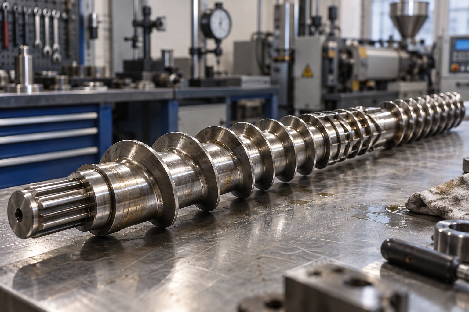
A barrier screw solves this problem with an elegantly simple modification. An additional flight - the barrier flight - is introduced across most of the compression zone, creating two parallel channels: one for the solid bed and one for the melt. The clearance between the barrier flight and the barrel wall is large enough to allow molten polymer to flow from the solids channel into the melt channel, but too small for unmelted pellets (typically around 1.5 mm in diameter) to pass through. As veteran extrusion engineer Allan Griff explains, the pellets stay in their main channel but are drained of excess melt, generating more frictional heat as they rub against one another - making melting more efficient per revolution.
The result for pipe producers is significant. The melt arriving at the metering zone is cleaner and more thermally uniform. Solid-bed breakup - a common source of pressure surges in conventional screws - is virtually eliminated. That translates into steadier melt pressure at the die and, ultimately, tighter wall-thickness tolerances on the finished pipe.
Barrier screws are commonly paired with a Maddock mixing section (also called a Union Carbide section) located in or near the metering zone. This device looks nothing like a conventional screw flight. Instead of helical channels, it features pairs of large longitudinal or helical flutes separated by a barrier ridge with a controlled clearance to the barrel - typically 0.50 to 0.75 mm. Melt enters the inlet flutes, is forced over the barrier ridge, and exits through adjacent outlet flutes. Any remaining unmelted particles are sheared and flattened as they attempt to cross the ridge, eventually passing through as melt.
Sounds complex? Think of the Maddock section as a final checkpoint. It performs two jobs at once for pipe applications:
- Dispersive mixing - The high-shear flow over the barrier ridge breaks down agglomerates and distributes pigments and additives evenly throughout the melt. For colored pipe, this prevents streaking and ensures consistent appearance along the entire length.
- Thermal homogenization - Cooler melt stays in the high-shear zone longer than hotter melt, narrowing the temperature spread across the melt stream. A tighter temperature profile means more uniform viscosity as the polymer enters the pipe die, which directly improves concentricity and surface finish.
In practice, a plastic single screw extruder configured for HDPE or PP-R pipe will almost always feature a barrier screw with a Maddock section. PVC pipe screws, because of the resin's thermal sensitivity, use simpler designs to minimize shear heating - but even PVC applications benefit from carefully positioned mixing elements when pigment distribution is critical.
Grooved Feed Barrels vs Smooth Bore Barrels
The feed section of the barrel is the one area where screw extruders for pipe diverge most dramatically based on the polymer being processed. The choice between a grooved feed barrel and a smooth bore barrel is not a minor preference - it fundamentally changes how solids are conveyed, how much pressure is generated in the feed zone, and what kind of screw design is required downstream.
Here is a side-by-side comparison of the two designs as they apply to pipe production:
| Feature | Grooved Feed Barrel | Smooth Bore Barrel |
|---|---|---|
| Typical Pipe Materials | Polyolefins (HDPE, PP-R, PE-RT) | PVC-U, PVC-C, and other thermally sensitive resins |
| Solids Conveying Mechanism | Friction-driven: grooves mechanically grip pellets against the barrel wall, preventing rotation with the screw | Viscous drag: relies on friction differential between barrel surface and screw root to advance the solid bed |
| Throughput Characteristics | Higher specific output (kg/hr per rpm); conveying efficiency can be several times greater than smooth bore | Lower specific output; more sensitive to head pressure, which creates reverse flow that reduces throughput |
| Pressure Generation | Very high feed-zone pressures (can exceed 12,000 psi); may offset or surpass discharge pressure | Moderate feed-zone pressure; discharge pressure has a more pronounced effect on output |
| Cooling Requirement | Intensive water cooling of the grooved section is required to prevent premature melting | Standard cooling at the feed throat; less demanding thermal management |
| Screw Design Compatibility | Requires a dedicated screw with shallower feed depth, deeper metering zone, and often a decompression section | Compatible with conventional three-zone and barrier screw designs |
Why do HDPE pipe producers almost universally use grooved feed extruders? HDPE pellets are slippery. In a smooth bore barrel, the low coefficient of friction between the pellets and the barrel wall limits conveying efficiency to roughly 15-30% of the channel volume, as extrusion specialist Jim Frankland notes. For a high-throughput pipe line running 16-inch HDPE pressure pipe, that lost efficiency is unacceptable. Grooved feed barrels grip the solid polymer mechanically, increasing conveying efficiency several times over. Testing on a 90-mm screw plastic extruder running fractional-melt HDPE demonstrated a 26.5% increase in output and a 27 degrees F reduction in melt temperature when switching from smooth bore to grooved feed - both metrics that directly benefit pipe quality and operating cost.
PVC pipe lines tell the opposite story. PVC is typically processed as a powder-based dry blend, not as pellets. The fine particles can plug grooves, and PVC's thermal sensitivity means the high pressures generated in a grooved feed section risk premature degradation. A smooth bore barrel with viscous drag conveying handles PVC dry blends reliably, and the screw design can be optimized specifically for PVC's narrow processing window. This is why the world's largest PVC pipe plants run smooth bore screw extruders without exception.
Compression Ratio Selection by Pipe Application
Compression ratio - the ratio of the feed-zone channel depth to the metering-zone channel depth - is one of the most frequently cited screw specifications, yet one of the most misunderstood. Many pipe processors assume there is a single "correct" ratio for a given polymer. The reality is far more nuanced.
The compression ratio must balance two competing demands. First, the feed zone needs to be deep enough to accept and convey the incoming polymer particles at a rate that keeps the screw fully charged. Second, the metering zone must be shallow enough to generate adequate shear heating to complete melting and to build the pressure required to push melt through the pipe die. The ratio between these two depths determines how much mechanical energy goes into the polymer during screw extrusion - and that directly controls both melt temperature and melt quality.
As a general principle, polyolefins like PE and PP typically start with compression ratios around 3:1, while nylon-based screws might use ratios closer to 4:1. PVC, with its sensitivity to shear and heat, calls for lower compression ratios - often in the range of 2:1 to 2.5:1 - to prevent degradation while still achieving proper gelation. These are starting points, not universal prescriptions. As Jim Frankland cautions, the compression ratio is an indefinite number that cannot properly describe a screw unless at least one channel depth is also known, and a host of variables - particle geometry, bulk density, friction coefficients, melt viscosity, and target exit temperature - all influence the ideal value.
For pipe extrusion specifically, consider several additional factors:
- Feed form matters. PVC dry blend has a much lower bulk density than HDPE pellets. A deeper feed channel compensates for the lower bulk density, but the metering depth must then be set to achieve the desired compression without introducing excessive shear into the heat-sensitive PVC melt.
- Grooved feed barrels change the equation. Because grooved feed sections generate high pressure independently, the screw can use a shallower feed depth and a deeper metering zone - sometimes with very little compression at all. This deeper metering zone improves pumping stability for polyolefin pipe but reduces mixing quality, which is why barrier and Maddock sections become essential companions.
- Recyclate complicates the picture. Pipe producers increasingly blend regrind or post-industrial recyclate into their feed. Low-bulk-density regrind may require a deeper feed section to fill the screw, yet the standard compression ratio for that polymer could deliver insufficient shear heating. Feeding and melting requirements should be determined separately rather than relying on a single "standard" ratio.
- Process type influences target melt temperature. A pressure-rated HDPE water pipe and a non-pressure HDPE drainage pipe may use the same resin grade but require different melt temperatures for optimal crystallization and long-term performance. That difference in target melt temperature feeds back into the ideal compression ratio.
The bottom line? Compression ratio is a critical design lever, but it works only when matched to the full context of your pipe application - polymer type, feed form, barrel design, target dimensions, and production speed. A screw with the "textbook" ratio for your resin can still underperform if those surrounding variables are ignored.
With screw geometry and barrel architecture mapped out, the logical next question becomes: how do these hardware choices change when you switch from one pipe resin to another? The answer varies more than most equipment catalogs admit, and the differences matter for every decision from screw metallurgy to barrel temperature setpoints.
Material-by-Material Extruder Configuration for Pipe
A single screw extruder that runs PVC beautifully can produce terrible HDPE pipe - and vice versa. That might sound obvious, yet most equipment catalogs list a single machine specification sheet and leave it to the buyer to figure out how the barrel type, screw geometry, and temperature strategy must shift for each resin. The truth is that every major pipe polymer demands a distinct extruder configuration, and treating a polymer extruder as a universal platform is the fastest route to inconsistent output and excessive scrap.
This section breaks down the critical configuration differences across the four most common pipe resins - PVC-U, HDPE, PP-R, and PEX - giving you a practical reference that most suppliers keep locked inside their engineering departments.
PVC Pipe Extrusion Configuration
PVC-U (unplasticized, rigid PVC) represents the single largest application for single screw extruders in the pipe industry worldwide. PVC-C, its chlorinated cousin used in hot-water and industrial piping, follows similar principles but with even tighter thermal constraints.
What makes PVC unique among pipe polymers is its narrow processing window. The temperature gap between proper gelation and the onset of thermal degradation is small - typically between 160 and 190 degrees Celsius at the barrel wall, as industry processing guides confirm. Push the melt too hot and you risk releasing hydrogen chloride gas, discoloring the pipe, and destroying the polymer's long-term mechanical properties. Run too cold and the PVC never fully gels, leaving a pipe with poor impact strength and a rough inner surface.
These thermal constraints dictate every hardware choice:
- Barrel type: Smooth bore, always. PVC is typically fed as a dry-blend powder, and the fine particles would clog barrel grooves. The lower feed-zone pressures of a smooth bore design also reduce frictional heat generation, keeping the temperature under control from the very start of the process.
- Compression ratio: Low, generally in the 2:1 to 2.5:1 range. A gentle compression minimizes shear heating, which is critical for a resin that degrades under excessive mechanical energy input.
- Screw design: Simple three-zone or mildly modified barrier designs. Aggressive mixing sections that work well on polyolefins can push PVC over its thermal limit. Mixing elements, when used, are designed for low-shear distributive blending rather than high-intensity dispersive shearing.
- Temperature profile: A gradually ascending profile through the feed and compression zones, often with a slight reduction or plateau near the metering zone to prevent overheating before the melt reaches the die.
It is worth noting that counter-rotating conical twin screw extruders are also widely used for PVC pipe, particularly when processing dry-blend powder at high output rates. However, single screw machines remain highly competitive for pre-compounded PVC pellets and for smaller-to-mid-diameter pipe lines where their lower capital cost and simpler operation deliver strong return on investment.
HDPE and PP-R Pipe Extrusion Configuration
Polyolefin pipe extrusion is a fundamentally different game. HDPE pressure pipe and PP-R hot-and-cold water pipe share enough similarities in processing behavior that their extruder configurations follow the same general architecture - though the details differ in important ways.
Both resins arrive as pellets, both tolerate a wider processing temperature window than PVC, and both benefit from aggressive melting and mixing. The extruder for polymer pipe in the polyolefin family looks noticeably different from a PVC-configured machine:
- Barrel type: Grooved feed, with intensive water cooling on the grooved section. As discussed in the previous chapter, the grooves mechanically grip slippery polyolefin pellets to dramatically increase conveying efficiency and throughput.
- Compression ratio: Higher than PVC - typically around 3:1 for PE grades. The more robust thermal stability of polyolefins allows greater shear input without degradation risk, and that extra mechanical energy contributes to thorough melting at high output rates.
- Screw design: Barrier flight screws with Maddock mixing sections are the standard for HDPE pipe. The barrier design separates the solid bed from the melt pool, virtually eliminating the risk of unmelted particles reaching the die. For PP-R pipe, a similar barrier screw approach applies, though a pp extruder may use slightly different flight geometry optimized for polypropylene's crystallization behavior.
- Temperature profile: Barrel temperatures generally range from 180 to 220 degrees Celsius depending on the specific resin grade and target melt temperature. HDPE pressure pipe often targets a lower melt temperature within the feasible range to promote slow crystallization and maximize long-term creep resistance - a nuance that feeds directly back into screw speed and compression ratio choices.
High-speed HDPE pipe extrusion lines often use screws with L/D ratios of 33:1 to 40:1, with the longer ratios delivering higher output rates and improved melt homogeneity at faster screw speeds. A 90-mm grooved-feed extruder with a 38:1 L/D ratio, for example, can achieve outputs of 1,000 to 1,100 kg/hr - throughput levels that would be difficult to reach with shorter screw lengths or smooth bore designs on the same diameter.
PEX and Specialty Pipe Considerations
Cross-linked polyethylene (PEX) pipe presents a unique challenge for single screw extrusion. The material starts as standard polyethylene but must either be cross-linked during the extrusion process (PEX-a, using peroxide initiated in the extruder) or after extrusion (PEX-b using silane grafting, PEX-c using electron beam irradiation). Each method places different demands on the plastic tube extruder.
PEX-a extrusion, for instance, requires the screw and barrel to handle a peroxide-initiated cross-linking reaction inside the barrel itself, demanding precise temperature control and specialized screw metallurgy to resist the corrosive byproducts of the reaction. PEX-b is more forgiving on the extruder side - the silane-grafted compound is processed much like standard HDPE, with cross-linking occurring later during a moisture-curing step. In both cases, the barrel and screw configuration starts from the HDPE baseline but adds application-specific modifications.
Emerging specialty pipe materials - including PE-RT (polyethylene of raised temperature resistance) for radiant heating systems and multilayer barrier pipes combining EVOH with polyolefin layers - further expand the range of configurations a single screw platform must accommodate. Each material brings its own melt behavior, thermal limits, and mixing requirements.
The table below consolidates the key configuration differences across all four major pipe resins into a single reference. Use it as a starting framework when specifying or evaluating extruder hardware for a specific pipe application.
| Pipe Material | Barrel Type | Screw Design Features | Key Process Considerations |
|---|---|---|---|
| PVC-U | Smooth bore | Simple three-zone or mild barrier; low-shear mixing elements; compression ratio 2:1 to 2.5:1 | Narrow thermal window (160-190 °C); avoid excessive shear; gradual ascending temperature profile; may require venting to remove volatiles |
| HDPE | Grooved feed with intensive water cooling | Barrier screw with Maddock mixing section; compression ratio ~3:1; L/D 33:1 to 40:1 for high-speed lines | Higher melt temperatures (180-220 °C); target lower melt temp within range for pressure pipe to optimize crystallization; high throughput demands grooved feed efficiency |
| PP-R | Grooved feed with water cooling | Barrier screw with mixing section; compression ratio similar to PE; flight geometry adjusted for PP melt rheology | Melt temperatures typically 200-240 °C; material is sensitive to oxidative degradation at high temps; screw design must balance mixing intensity with residence time |
| PEX | Grooved feed (similar to HDPE baseline) | Barrier screw; metallurgy selected for corrosion resistance (especially PEX-a peroxide process); may include specialized mixing zones | PEX-a requires precise in-barrel cross-linking control; PEX-b processes like HDPE with post-extrusion curing; screw and barrel materials must resist peroxide and silane chemistry |
This matrix highlights a fundamental point: a single screw extruder for pipe is never truly a one-size-fits-all machine. The barrel bore, the screw flight architecture, the compression ratio, and the temperature strategy all shift - sometimes dramatically - depending on which polymer you are running. Recognizing those shifts before you buy, rather than discovering them on the production floor, separates a well-specified line from an expensive compromise.
Of course, material configuration is only half the equation. Many pipe producers also weigh single screw systems against twin screw alternatives, especially for PVC. The right choice depends not on which technology is "better" in the abstract, but on which one aligns with your specific product portfolio and production goals - a comparison that reveals some surprising trade-offs.
Single Screw vs Twin Screw Extruders in Pipe Applications
Most comparisons between single screw and twin screw extruders read like a generic plastics processing textbook - listing mixing intensity, shear rates, and throughput numbers without ever telling you which machine makes better pipe. That vagueness is unhelpful when you are standing in front of a capital expenditure decision with a specific product line to fill. The real question is not which extruder architecture is superior in the abstract. It is which one matches your pipe material, your target diameter range, and your production economics.
The material configuration matrix in the previous section already hinted at the answer for each resin. This section makes the comparison explicit, covering the scenarios where single screw technology dominates, where a twin screw extruder earns its higher price tag, and how your product portfolio should ultimately drive the decision.
Where Single Screw Extruders Excel in Pipe Production
For the vast majority of single-layer thermoplastic pipe produced worldwide, the single screw extruder is the default choice - and for good reason. When you are running HDPE pressure pipe, PP-R plumbing pipe, or PVC pipe from pre-compounded pellets, a properly configured single screw machine delivers everything the application demands: stable melt pressure, consistent output, and tight dimensional control over continuous production runs that can stretch across multiple shifts.
Why does this architecture dominate? Consider what pipe extrusion actually requires. Unlike compounding or reactive processing, pipe production is fundamentally a melting-and-pumping operation. The polymer enters as pellets or granules that are already fully formulated. No intensive blending of disparate components is needed inside the barrel. The extruder's job is to melt that material uniformly, build consistent pressure, and deliver it to the die at a rock-steady flow rate. A single extruder screw - especially a barrier design with a Maddock mixing section - handles those tasks with elegant efficiency.
The practical advantages stack up quickly for pipe producers:
- Lower capital investment - A single screw system typically costs 30-50% less than a comparable twin screw setup, freeing budget for downstream equipment or additional production lines.
- Simpler operation - Fewer process variables to manage means shorter operator training cycles and less risk of human error during production.
- Reduced maintenance burden - One screw, one barrel bore, one set of wear surfaces. Spare parts inventory shrinks, and planned maintenance windows are shorter.
- Excellent energy efficiency - Single screw designs, particularly grooved feed extruders running polyolefins, convert a high percentage of motor energy into useful melt conveying rather than internal friction losses.
For HDPE and PP-R pipe specifically, single screw extrusion is not just a viable option - it is the industry standard across virtually all diameter ranges, from small 20-mm plumbing tubes to large-diameter 1,600-mm infrastructure pipe. The grooved feed barrel and barrier screw combination delivers the throughput and melt quality these polyolefins demand without the mechanical complexity of a double screw extruder.
When Twin Screw Extruders Are Preferred for Pipe
Twin screw extrusion enters the pipe conversation primarily through one material: PVC. And even within PVC pipe production, the choice is more nuanced than most suppliers admit.
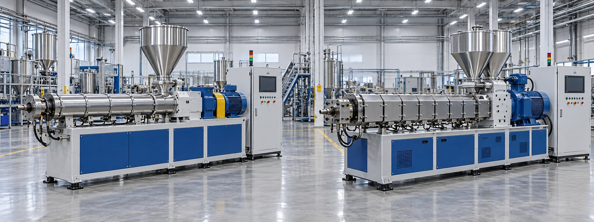
A counter-rotating conical twin screw extruder is widely regarded as the industry standard for processing PVC dry-blend powder into rigid pipe. The intermeshing screws provide superior distributive and dispersive mixing, excellent temperature control for this heat-sensitive polymer, and strong conveying force that handles low-bulk-density powder efficiently. For factories running PVC pipe from in-house dry-blend formulations - especially at high output rates or large diameters - twin screw systems offer clear technical and economic advantages in mixing performance, thermal stability, and formulation flexibility.
A parallel twin screw extruder occupies a different niche. It is less common for standard PVC pipe but finds application in specialty compounded pipe materials, filled PVC formulations with high calcium carbonate content, and situations where modular screw configurations need to adapt to changing production requirements. Co-rotating parallel twin screw designs, meanwhile, are primarily used for compounding and pelletizing rather than direct pipe extrusion.
Twin screw extrusion also becomes relevant for pipe producers who need to:
- Process PVC dry-blend formulations with variable filler loadings or recycled PVC content
- Achieve the highest possible output rates on large-diameter rigid PVC pipe
- Handle specialty compounds requiring intensive mixing or degassing inside the barrel
The trade-off? Higher equipment cost, more complex gearbox and screw assemblies, greater maintenance demands, and the need for operators with deeper process knowledge. For pipe manufacturers who process only pre-compounded PVC pellets at modest volumes, a single screw machine often delivers equivalent pipe quality at a fraction of the total cost of ownership.
The following table distills the comparison into the parameters that matter most for pipe production decisions:
| Parameter | Single Screw Extruder | Twin Screw Extruder |
|---|---|---|
| Capital Cost | Lower; simpler mechanical design reduces upfront investment | Higher; complex gearbox, dual-screw assembly, and tighter manufacturing tolerances increase cost |
| Best Pipe Materials | HDPE, PP-R, PE-RT, PEX, and PVC from pre-compounded pellets | PVC-U from dry-blend powder; specialty filled or modified PVC compounds |
| Typical Pipe Diameter Range | Full range: 16 mm up to 1,600 mm+ for polyolefin pipe | Most common for medium to large PVC pipe; conical twin screw covers 16-630 mm in standard configurations |
| Operational Complexity | Lower; fewer process variables, shorter training requirements | Higher; requires deeper understanding of screw element configuration, PVC formulation behavior, and thermal management |
| Throughput Range | Wide range depending on screw diameter; grooved feed designs achieve very high specific output on polyolefins | High output on PVC dry blend; conical designs excel at stable throughput with heat-sensitive materials |
| Maintenance Requirements | Lower; single screw and barrel wear set, simpler gearbox, fewer components | Higher; dual screw replacement, more complex gearbox servicing, tighter wear tolerances on intermeshing elements |
Choosing Based on Your Pipe Product Portfolio
Here is the decision framework that most equipment brochures will never lay out this plainly:
If your production centers on polyolefin pipe - HDPE water mains, PE gas pipe, PP-R plumbing, PE-RT underfloor heating lines - a single screw extruder with a grooved feed barrel and barrier screw is almost always the right choice. Twin screw extrusion offers no meaningful advantage for these materials and adds cost and complexity you do not need.
If you produce PVC pipe from dry-blend powder and require high output rates, formulation flexibility, or the ability to handle variable filler content, a conical twin screw extruder is the conventional path. It delivers the controlled plasticizing and low-shear mixing that PVC dry blend demands.
If you run PVC pipe from pre-compounded pellets at low to moderate volumes, single screw technology becomes genuinely competitive again. The pellets arrive already well-mixed and thermally homogenized, which eliminates the primary mixing advantage that twin screw extrusion brings to PVC processing. In this scenario, the single screw machine's lower cost, simpler maintenance, and straightforward operation can tip the total cost-of-ownership calculation in its favor.
Many pipe manufacturers operate mixed product portfolios - producing both polyolefin and PVC pipe across multiple lines. In those facilities, you will typically find single screw extruders dedicated to the PE and PP-R lines and twin screw machines handling the PVC dry-blend lines. Trying to force one architecture to do everything usually means compromising performance on at least one material.
Regardless of which extruder type you select, the machine itself is only one station in a much longer production sequence. How well that extruder integrates with the die head, vacuum calibration tank, cooling system, and haul-off determines whether your theoretical specifications translate into actual pipe quality on the factory floor.
How the Extruder Integrates Into a Complete Pipe Production Line
A perfectly configured extruder means nothing if the equipment downstream cannot keep pace. Imagine spending months selecting the ideal barrel type, screw geometry, and drive system for your HDPE pipe line - only to discover that your vacuum calibration tank cannot cool the pipe fast enough to hold dimensional tolerances at the output rate your extruder delivers. That mismatch is more common than most suppliers will admit, because most suppliers sell extruders, not complete production systems.
The single screw extruder is the heart of a pipe line, but it beats inside a body of interdependent stations. Each one must be sized, positioned, and synchronized to work as part of a continuous process. Understanding that full sequence - and where the critical handoffs occur - is what separates a plastic extruder machine purchase from a functioning pipe production investment.
From Extruder Output to Pipe Die and Calibration
The melt leaves the extruder's metering zone and passes through a screen pack mounted on a breaker plate. This assembly serves two purposes: it filters out contaminants or partially unmelted particles, and it generates back-pressure that improves melt homogeneity. From there, the clean, pressurized melt flows into the pipe die head.
Two die head architectures dominate pipe production. Spider dies use internal support legs (spiders) to hold the central mandrel in position, creating the hollow core of the pipe. They are widely used for PVC pipe. Spiral mandrel dies distribute the melt through overlapping helical channels that wrap around the mandrel, producing a more uniform wall distribution and eliminating the weld lines that spider legs can leave behind. These are the standard choice for polyolefin pipe, as Rollepaal's component optimization research confirms - spiral mandrel and basket dies are preferred for PE, while spider dies with double compression tooling remain common for PVC.
The moment the molten pipe exits the die, it enters the vacuum calibration tank. A calibration sleeve inside the tank defines the pipe's outer diameter. Vacuum pressure draws the still-soft pipe wall outward against the sleeve's inner surface, while water jets cool and solidify the outer skin. This is the first point where the pipe locks into its final shape.
Here is the critical connection most equipment discussions miss: the extruder's melt pressure stability directly determines how well the pipe calibrates. Pressure surges from the extruder cause the molten pipe to pulse - expanding against the calibration sleeve during a high-pressure moment and pulling away during a low-pressure dip. The result is ovality, wall thickness variation, and surface imperfections that no amount of downstream adjustment can fix. A plastic extruding machine with unstable discharge pressure makes every downstream station work harder and less effectively.
Downstream Equipment and Line Speed Matching
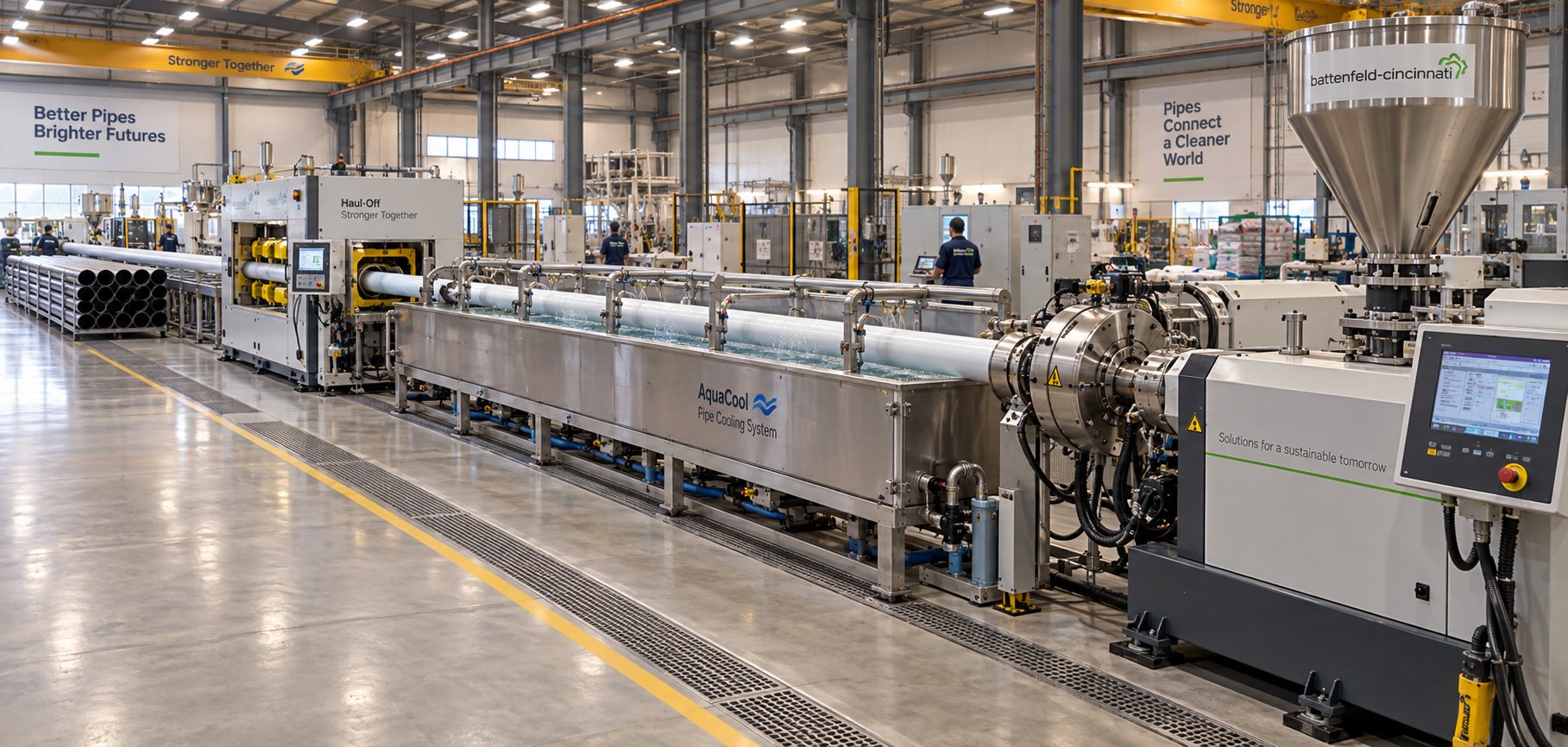
A complete pipe extrusion line is not a collection of standalone machines. It is a single continuous process, and every station must operate in precise harmony. Here is the full production sequence from raw material to finished product:
- Single screw extruder - Melts, homogenizes, and pressurizes the polymer.
- Pipe die head - Shapes the melt into a hollow cylindrical profile.
- Vacuum calibration tank - Sets the outer diameter and begins solidifying the pipe wall.
- Spray or immersion cooling tanks - Remove remaining heat to fully solidify the pipe through its entire wall thickness.
- Haul-off unit - Pulls the cooled pipe at a controlled, constant speed using caterpillar tracks or belts.
- Cutting unit - Cuts pipe to specified lengths using a planetary cutter for thick-walled products or a flying saw for high-speed lines.
- Socketing or belling station (if applicable) - Forms an expanded socket on one end of each pipe length for push-fit joining.
- Stacking or coiling system - Stacks rigid pipe lengths for packaging or coils flexible small-diameter pipe onto drums.
The relationship that governs this entire chain is deceptively simple: the extruder's output rate in kilograms per hour must match the haul-off speed and cooling capacity to produce pipe within specification. As detailed synchronization analysis from Jinxin Extruder explains, if haul-off speed increases while extruder output stays constant, the pipe stretches - wall thickness drops, outer diameter shrinks, and meter weight falls below target. If the extruder pushes more material than the haul-off removes, the pipe wall thickens, the product may sag before it cools, and dimensional stability deteriorates.
Cooling capacity adds another constraint. A larger-diameter pipe has more thermal mass and requires longer cooling tanks - or slower line speeds - to solidify completely before reaching the haul-off. If you upgrade your extruder to boost throughput without extending cooling capacity, you will either run with an incompletely solidified pipe (causing deformation at the haul-off) or throttle back the extruder to a speed your cooling tanks can handle, wasting the output potential you paid for.
This is precisely why purchasing extruding equipment in isolation - without evaluating the die, calibration, cooling, haul-off, and cutter as an integrated system - leads to suboptimal performance. The best extruder on the market, paired with undersized downstream equipment, produces worse pipe than a modest extruder matched to a well-balanced line.
Line integration also extends to control systems. Modern pipe lines use centralized PLC and HMI platforms that coordinate screw speed, haul-off speed, vacuum pressure, and cooling water flow in real time. Gravimetric feeders and inline laser gauges feed dimensional data back to the control system, enabling automatic corrections that keep wall thickness and outer diameter within tolerance without constant operator intervention. When evaluating a line, the control architecture deserves as much scrutiny as the mechanical hardware.
With the full production line mapped out, the next logical step is quantifying the technical parameters that tie these stations together - L/D ratios, screw diameters, temperature profiles, and output rate expectations that let you evaluate whether a specific extruder actually fits your pipe production targets.
Critical Technical Parameters for Pipe Extrusion
Equipment brochures love big numbers - maximum output rates, peak motor horsepower, impressive screw diameters. But when you sit down to evaluate whether a specific single screw extrusion machine actually fits your pipe production targets, those headline figures tell only part of the story. The parameters that truly determine pipe quality and production economics live deeper inside the specification sheet, and understanding how they interact is what separates a well-informed purchase from an expensive gamble.
This section breaks down the technical specifications that matter most for pipe extrusion, explains what each one means in practical terms, and gives you a checklist of details to demand from any industrial extruder supplier before you sign a purchase order.
L/D Ratio and Screw Diameter Selection for Pipe
The length-to-diameter ratio - universally written as L/D - describes how long the screw is relative to its bore diameter. A 90-mm extruder with a 30:1 L/D ratio has a screw roughly 2,700 mm long from the start of the feed zone to the tip. Simple math, but the performance implications are anything but simple.
Why does a longer screw matter for pipe? More length means more barrel surface area for heat transfer, more residence time for melting and mixing, and more channel turns for homogenizing the melt before it reaches the die. For pipe applications, where even small temperature gradients across the melt stream translate into wall thickness variation and concentricity problems, that extra homogenization is not a luxury - it is a requirement.
The most common L/D ratio across general extrusion is around 24:1, with some machines reaching 30:1 or longer. Pipe extrusion, however, routinely demands ratios at the higher end of that range. Modern polyolefin pipe extruders typically operate with L/D ratios of 30:1 to 36:1, and high-speed HDPE pipe lines increasingly push toward 38:1 or even 40:1 to achieve the throughput and melt quality that pressure-rated pipe demands. PVC pipe extruders, by contrast, often sit closer to the 24:1 to 28:1 range, because PVC's thermal sensitivity means that excessive residence time in the barrel increases the risk of degradation.
Screw diameter selection follows a different logic. It is driven primarily by your target output rate and the pipe dimensions you need to produce. A small-diameter screw - say 45 mm or 60 mm - suits small-bore plumbing pipe produced at modest volumes. Large-diameter infrastructure pipe (400 mm and above) demands extruders with screw diameters of 90 mm, 120 mm, or even larger to deliver the hundreds or thousands of kilograms per hour the die requires. Oversizing introduces its own problems: running a large-diameter extruder at very low screw speeds to match a modest output target leads to poor mixing, longer residence times, and inconsistent melt quality. The extruder should be sized to run within its optimal operating window - typically 40-80% of maximum rated screw speed - under normal production conditions.
Temperature Profiles and Output Rate Expectations
Every pipe material requires a distinct barrel temperature profile, and the correct profile depends on the interaction between barrel zone setpoints, screw speed, and the shear heat generated by the screw geometry itself. Barrel heaters provide part of the thermal energy; mechanical shear from the screw provides the rest. At higher screw speeds, shear heating increases, and the barrel cooling system must compensate to prevent the melt from overshooting the target temperature. At lower speeds, the heaters carry more of the load.
For pipe processors evaluating a new single screw extruder for pipe, the table below captures the key technical parameters, their significance for pipe quality, and the general ranges you should expect to see on a well-specified machine. Use these as benchmarks when comparing quotations - not as absolute values, since every pipe application has its own optimum.
| Parameter | Significance for Pipe Quality | General Range for Pipe Extrusion |
|---|---|---|
| L/D Ratio | Longer ratios improve melt homogeneity and reduce temperature gradients; critical for pressure-rated pipe with tight dimensional tolerances | 24:1 to 28:1 for PVC pipe; 30:1 to 40:1 for polyolefin pipe (HDPE, PP-R) |
| Screw Diameter | Determines maximum throughput capacity; must be matched to target pipe size and output requirements | 45-75 mm for small-bore pipe; 75-120 mm for medium pipe; 120-200 mm+ for large-diameter infrastructure pipe |
| Screw Speed (RPM) | Higher RPM increases output but also raises shear heating; excessive speed degrades heat-sensitive materials and increases wear | 60-150 RPM typical for pipe; PVC lines often run at the lower end (40-80 RPM) to limit shear heat |
| Barrel Zone Temperatures | Each zone's setpoint must match the polymer's melting and flow behavior; incorrect profiles cause degradation, poor gelation, or surface defects | PVC: 150-190 °C across zones; HDPE: 180-220 °C; PP-R: 200-240 °C (ascending profile through feed and compression, with plateau or slight reduction near the die) |
| Melt Pressure at Die | Stability is more important than absolute value; pressure fluctuations directly cause wall thickness variation and ovality | 150-400 bar depending on die geometry, pipe size, and material; variation should be held below +/- 2-3% for quality pipe |
| Output Rate | Must match downstream cooling capacity and haul-off speed; overshooting creates bottlenecks elsewhere in the line | Depends heavily on screw diameter and material; a 60-mm extruder may produce 80-200 kg/hr; a 90-mm grooved feed machine on HDPE can reach 800-1,100 kg/hr |
A few relationships in this table deserve special attention. Notice how screw speed interacts with barrel zone temperatures - especially for PVC. Running a PVC pipe extruder at high RPM to chase output forces the cooling system to remove excess shear heat, which narrows your process window and increases the risk of localized degradation. Experienced processors often find that a slightly larger screw diameter running at moderate speed produces better pipe at the same output rate than a smaller machine pushed to its limit. The plastic extruder machine price difference between a 75-mm and 90-mm system may be modest, but the quality and consistency gap can be substantial.
Melt pressure stability warrants its own emphasis. A spec sheet that lists maximum die pressure tells you almost nothing useful. What matters is how tightly the extruder holds that pressure during continuous operation. Ask the supplier for pressure variation data at your target operating conditions. If they cannot provide it, that itself is valuable information about the machine's suitability for pipe production.
Specifications to Evaluate When Purchasing
When you request a quotation for a single screw extrusion machine, the initial offer typically highlights screw diameter, L/D ratio, motor power, and maximum output. Those numbers get the conversation started, but they do not give you enough information to predict how that machine will perform on your specific pipe product. Here is a checklist of the specifications you should be evaluating - and requesting from every supplier - before making a commitment:
- Drive motor power and torque curve - Motor kilowatts alone do not tell the full story. The torque curve shows how much turning force is available across the full RPM range. Pipe extrusion often operates at moderate speeds where sustained torque, not peak power, determines whether the screw can maintain stable output against die resistance.
- Gearbox rating and service factor - The gearbox transmits motor torque to the screw. Its rated torque capacity and service factor (the safety margin above continuous operating load) determine long-term reliability. An undersized gearbox is one of the most common causes of premature failure on pipe extruders.
- Barrel material and bore hardness - Standard nitrided steel barrels work for unfilled polymers, but abrasive fillers (calcium carbonate in PVC, glass fiber in specialty pipe) demand bimetallic linings with hardness ratings above 55 HRC. Knowing the barrel metallurgy tells you how long the bore will hold its dimensional tolerance before wear degrades output and quality.
- Screw metallurgy and surface treatment - Flight surfaces closest to the barrel wall experience the most wear. Options range from flame-hardened flights for light-duty applications to hard alloy caps on flight tips and full nitriding for heavier service. The correct choice depends on the polymer, filler content, and expected production volume.
- Number of heating and cooling zones - More zones provide finer temperature control along the barrel length. Pipe extrusion typically benefits from a minimum of four to six independently controlled barrel zones plus a separately controlled die zone. Fewer zones mean coarser control and wider temperature swings.
- Cooling method and capacity - Air-cooled barrel zones respond slowly and are adequate for many applications. Water-cooled zones react faster and are essential for grooved feed sections and for materials like PVC where tight thermal management is non-negotiable. Verify that the cooling capacity matches the heat load at your target screw speed.
- Control system capabilities - A modern PLC with HMI touchscreen should offer zone-by-zone temperature control, screw speed regulation, melt pressure monitoring, and alarm thresholds. Data logging and trend display are increasingly standard and valuable for troubleshooting and quality documentation.
- Screw and barrel clearance specification - New screws typically maintain a flight-to-barrel clearance between 0.125 and 0.25 mm, with tighter gaps on smaller machines and wider gaps on larger bores. This clearance affects leakage flow, shear heating, and mixing. Ask the supplier to state both the new-build clearance and the wear limit at which the screw should be replaced.
The pvc extrusion machine price - or the price of any pipe extruder - becomes meaningful only when you can compare it against this full set of specifications. Two machines with identical screw diameters and motor ratings can perform very differently if one uses a bimetallic barrel with a high-torque gearbox while the other cuts costs on metallurgy and drive components. Requesting detailed specifications levels the playing field and forces every supplier to compete on substance rather than headlines.
Technical parameters define what a machine can do. But parameters are only as good as the screw and barrel assembly that delivers them - and that is where the distinction between off-the-shelf components and purpose-engineered hardware becomes impossible to ignore.
Selecting the Right Screw and Barrel for Your Pipe Application
Equipment manufacturers love the phrase "tailor-made extrusion solutions." It sounds impressive on a brochure. But what does customization actually mean when you are specifying a screw and barrel for pipe production? For most buyers, the answer is frustratingly vague - until something goes wrong on the production floor and the real cost of generic components becomes painfully clear.
The previous section laid out the technical parameters that define a pipe extruder's capability. Those numbers, however, describe the machine's potential. Whether that potential translates into consistent, in-spec pipe depends almost entirely on one component pair: the screw and barrel. A drive motor delivers torque. A gearbox transmits it. But the screw and barrel are where polymer meets metal, where raw pellets become molten pipe wall, and where every design shortcut or material mismatch announces itself in defects, downtime, and wasted resin.
Why Off-the-Shelf Screws Underperform in Pipe Applications
Picture this scenario. A pipe manufacturer buys a replacement screw from a general-purpose supplier. The diameter matches, the length is correct, and the price is attractive. Production restarts, and within a few hours the problems begin: wall thickness variation creeps outside tolerance, the melt pressure gauge shows wider swings than before, and scrap rates climb. The screw fits the barrel mechanically, but its geometry was never designed for the specific polymer, pipe dimensions, or production speed this line requires.
This is not an unusual story. It plays out regularly at pipe plants that treat screws and barrels as commodity spare parts rather than engineered components. As the BLOOM engineering team emphasizes, treating screws as generic replacements is the most expensive mistake buyers make - the same-diameter screw is built differently for PVC, PET, or glass-filled nylon because the geometry, steel, and coating must match the material and the product.
For pipe extrusion specifically, the penalties of a mismatched screw compound quickly:
- Inconsistent melt quality - A compression ratio designed for general-purpose extrusion may deliver incomplete melting for your specific pipe resin, embedding solid particles in the pipe wall that create weak points under pressure testing.
- Reduced output - A screw with the wrong flight geometry for your barrel type - say, a smooth bore screw design running in a grooved feed barrel - disrupts the pressure balance between feed zone and metering zone, throttling throughput well below the machine's rated capacity.
- Higher scrap rates - When melt temperature uniformity suffers, every downstream process - calibration, cooling, dimensional control - works harder and less effectively. Reject rates that were running at 2-3% on the original screw can spike to 8-10% or more on a poorly matched replacement.
- Accelerated wear - A screw metallurgy that works fine for unfilled polyolefin will erode rapidly when processing PVC compounds containing calcium carbonate filler. Flight clearance opens up within months instead of years, and both screw and barrel suffer damage that compounds with every operating hour.
Worn screws create a parallel problem. As the flight-to-barrel clearance increases beyond the original specification - roughly the screw diameter divided by 1,000 per side for a new assembly - melt leaks backward over the flights. Output drops, melt temperature rises from the recirculating material, and dimensional stability deteriorates. A pipe processor running a worn screw is paying for polymer that never reaches the die, heating energy that produces no useful product, and quality problems that consume operator time and customer confidence.
The economics are straightforward. Investing in a properly engineered screw and barrel matched to your pipe application costs more upfront than grabbing the cheapest replacement that fits. But the payback in output consistency, scrap reduction, energy savings, and extended service life almost always favors the application-specific solution - often dramatically. Industry data suggests that bimetallic barrel construction, while approximately 25% more expensive initially, can reduce total cost of ownership by roughly 50% over a three-year period in abrasive applications, thanks to lifespan extensions of two to three times and wear rate reductions exceeding 60%.
What to Look for in a Screw and Barrel Supplier
Finding a plastic extruder for sale is easy. Finding a supplier who can engineer and deliver screw and barrel components that actually optimize your pipe line's performance - and keep doing so across multiple replacement cycles - requires a more deliberate evaluation.
Not every single screw extruder manufacturer has the metallurgical capability, design engineering depth, or application knowledge to produce pipe-specific screw and barrel assemblies. Trading companies that resell components from unknown workshops are common in the market, and their products may look identical in a photograph but perform very differently inside a barrel running at 200 degrees Celsius with calcium carbonate-filled PVC. The following criteria separate genuine engineering partners from parts brokers:
- Material-specific screw design capability - The supplier should be able to explain how they would configure a screw differently for PVC-U pipe versus HDPE pressure pipe versus PP-R hot water pipe. If they offer a single "pipe screw" design regardless of polymer, that is a red flag. Each resin demands distinct compression ratios, barrier flight geometry, and mixing section configurations, as the material matrix earlier in this article detailed.
- Custom compression ratio engineering - A competent supplier calculates the compression ratio based on your specific feed material (pellets vs. powder, virgin vs. recyclate), bulk density, target melt temperature, and barrel type (grooved vs. smooth bore). They should ask you detailed questions about your process before quoting, not simply offer a catalog number.
- Surface treatment and coating options for wear resistance - Different pipe applications create different wear environments. Unfilled PVC requires corrosion resistance against hydrochloric acid released during processing. HDPE with mineral fillers demands abrasion-resistant flight surfaces. A capable plastic profile extruders supplier offers a range of treatments - nitriding for light duty, hard chrome plating for corrosion protection, bimetallic linings for abrasive service, and tungsten carbide hardfacing for extreme wear - and recommends the right one based on your actual material, not the most expensive option on the shelf.
- Replacement barrel availability and lead time - Pipe plants run continuously. When a barrel reaches its wear limit, you need a replacement quickly, built to the same specification as the original. Evaluate whether the supplier maintains production capacity for barrel manufacturing and can deliver within a timeframe that aligns with your planned maintenance windows.
- Technical support for process optimization - The best screw and barrel suppliers do not disappear after the invoice clears. They provide guidance on temperature profiles, screw speed settings, and troubleshooting when the new components go into service. Engineering support capacity - verified by the size and experience of the supplier's technical team - is a reliable indicator of long-term partnership potential.
For pipe manufacturers seeking custom or replacement single screw barrels, NANHAIYA's single screw barrel solutions represent the kind of application-specific approach this evaluation framework demands. NANHAIYA provides custom and replacement single screw barrels engineered for pipe, film, sheet, pelletizing, recycling, and general-purpose extrusion lines - covering the range of configurations a pipe processor might need across different production lines or material transitions. Their ability to supply barrels matched to specific pipe extrusion requirements makes them a practical resource when you need components designed for your process rather than pulled from a generic inventory.
Beyond the supplier's technical capabilities, there is a procurement discipline that protects you throughout the relationship. Always request material certificates documenting the steel grade, heat treatment parameters, and surface hardness of every screw and barrel delivered. Specify the new-build clearance and the acceptable wear limit in the purchase order. And whenever possible, start with a single-unit trial to validate the supplier's quality against your actual production conditions before committing to volume purchases. A plastic extruder machine for sale at an attractive price means nothing if the screw and barrel it ships with cannot hold dimensional tolerances on your pipe product.
The screw and barrel you select today defines your production reality for the next several years. But the technology inside these components is not standing still. Advances in barrel linings, screw coatings, drive efficiency, and process monitoring are reshaping what pipe processors can expect from their extrusion hardware - and creating upgrade opportunities that were not available even a few years ago.
Emerging Pipe Applications and Extruder Technology Advances
Pipe markets do not stand still. Infrastructure spending is accelerating worldwide, building codes are tightening performance requirements, and entirely new pipe constructions - multi-layer barrier systems, fiber-reinforced composites, large-bore municipal conduits - are shifting from niche curiosities into mainstream demand. Each of these trends places fresh demands on plastic extruders, and single screw technology is evolving to meet them. Understanding where the technology is headed helps you make capital equipment decisions that remain competitive not just today, but across the useful life of the line you install.
Multi-Layer and Reinforced Pipe Extrusion
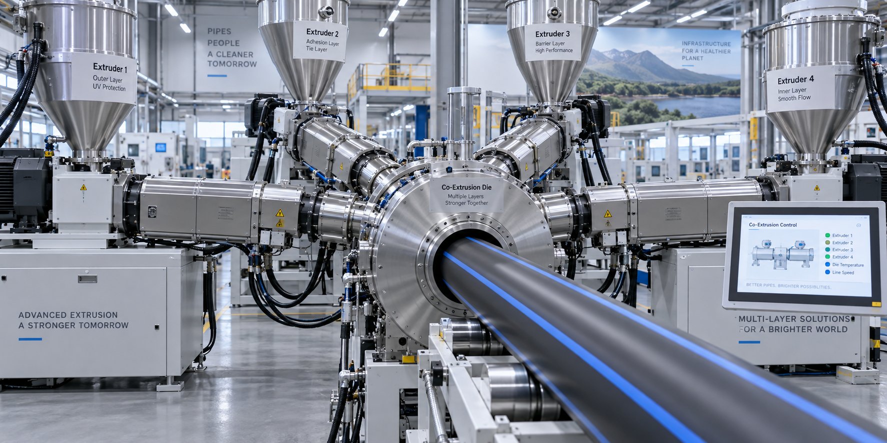
Imagine a radiant heating pipe that must carry hot water for decades without allowing oxygen to permeate through the wall and corrode the metal components in the system. A single layer of PE-RT or PEX cannot do that alone. The solution is a multi-layer co-extruded pipe - typically PE-RT on the inner and outer layers with a thin EVOH (ethylene vinyl alcohol) barrier sandwiched between adhesive tie layers. Producing that five-layer structure requires multiple single screw extruders feeding a single co-extrusion die head simultaneously, each one precisely matched to its assigned layer material and thickness.
PE/aluminum composite pipe pushes the concept further. Here, a thin aluminum tube is continuously welded inline and bonded between inner and outer polyethylene layers using adhesive resins. The plastic extruders supplying the PE layers must deliver extraordinarily stable melt flow, because even minor output fluctuations cause delamination at the adhesive interface - a defect that is invisible on the surface but catastrophic in service.
At the other end of the diameter spectrum, large-bore infrastructure pipe is driving demand for bigger extrusion hardware. Municipal water transmission mains and stormwater conduits in HDPE now routinely reach diameters of 1,200 mm to 2,000 mm. Producing pipe at these sizes requires extruders with screw diameters of 150 mm and above, gearboxes rated for enormous sustained torque, and barrel assemblies long enough to fully homogenize hundreds of kilograms of polyethylene per hour. The plastics extrusion equipment serving this segment has scaled up considerably, and further growth is expected as aging concrete and steel infrastructure is replaced with corrosion-resistant thermoplastic alternatives.
Co-extrusion also opens the door for cost optimization in standard pipe. A growing number of producers use a two-extruder configuration to apply a thin outer skin of virgin pigmented material over a core layer containing regrind or post-consumer recyclate. The outer extruder - often a smaller single screw machine - wraps a pristine, UV-stabilized surface around a structurally sound but visually imperfect core. Both extruders must maintain tight output synchronization, reinforcing the principle from earlier sections that line integration matters as much as individual machine capability.
Advances in Screw and Barrel Technology for Pipe
The screw and barrel may be the oldest components in the extrusion line, but they are far from static. Recent developments in materials science, surface engineering, and digital process control are delivering measurable improvements in throughput, energy efficiency, and component lifespan - benefits that pipe producers can capture through targeted upgrades even on existing machines.
Several technology trends are reshaping what pipe processors should expect from their screw and barrel assemblies:
- Advanced bimetallic barrel linings - Modern centrifugally cast bimetallic barrels bond a wear-resistant alloy layer to the inner bore of a structural steel outer shell. These linings - based on iron-boron, nickel-boron, or tungsten carbide composites - dramatically extend barrel life when processing abrasive formulations like filled PVC or mineral-reinforced polyolefin pipe. As referenced earlier, bimetallic construction can extend service life by two to three times compared to standard nitrided barrels, reducing replacement frequency and total cost of ownership.
- High-performance screw coatings - Hard chrome plating has long been the default screw surface treatment, but newer options are gaining traction. PVD (physical vapor deposition) coatings such as chromium nitride and DLC (diamond-like carbon) offer higher hardness, lower friction coefficients, and improved corrosion resistance. For pipe extrusion, lower screw surface friction translates into reduced shear heating - particularly valuable for thermally sensitive PVC - and improved energy efficiency across all materials.
- Servo-driven extruders for energy savings - Traditional AC motor and gearbox drives are being replaced by direct-drive servo motor systems on new pipe extruders. Servo drives deliver precise speed control across the full RPM range, eliminate energy losses in belt drives and fluid couplings, and reduce specific energy consumption. Industry reports indicate energy savings of 10-15% compared to conventional drive trains, with some advanced configurations achieving reductions of up to 30% in specific energy consumption.
- Inline quality monitoring systems - Ultrasonic wall thickness gauges, laser diameter sensors, and gravimetric throughput measurement devices now feed real-time data into the extruder's control system. Closed-loop feedback adjusts screw speed, barrel temperatures, and haul-off velocity automatically, keeping pipe dimensions within tolerance without constant operator intervention. These systems transform the extruder from a standalone machine into an intelligent node within a self-correcting production line.
For pipe manufacturers looking to upgrade existing lines rather than invest in entirely new plastics extrusion equipment, replacing the screw and barrel is often the highest-impact, lowest-disruption path. A worn barrel swapped for a modern bimetallic unit with tighter bore tolerances can restore - or exceed - original output rates and dimensional consistency without touching the drive, gearbox, or frame. Suppliers like NANHAIYA, who offer custom single screw barrel solutions with contemporary coating and alloy technologies, provide a practical entry point for pipe processors seeking to capture these technology advances on their current equipment.
The trajectory is clear. Single screw extrusion for pipe is not a mature technology coasting on inertia. It is an actively evolving platform where incremental gains in screw metallurgy, barrel construction, drive efficiency, and digital process control compound into meaningful competitive advantages over time. The pipe producers who stay ahead are not necessarily the ones buying the most expensive new machines - they are the ones who understand which upgrades deliver real returns on their specific products, materials, and production targets. That understanding, more than any single equipment purchase, is what separates a pipe plant that merely operates from one that consistently outperforms.
Frequently Asked Questions About Single Screw Extruders for Pipe
1. What is the difference between a grooved feed barrel and a smooth bore barrel for pipe extrusion?
Grooved feed barrels use machined grooves in the feed section to mechanically grip polymer pellets, generating high feed-zone pressure and significantly boosting throughput. They are standard for polyolefin pipe materials like HDPE and PP-R. Smooth bore barrels rely on viscous drag to convey material and are the preferred choice for PVC pipe, which is typically processed as a powder-based dry blend. Using the wrong barrel type for your pipe resin can cause conveying problems, premature degradation, or severely reduced output.
2. Why is a barrier screw recommended for pipe extrusion over a standard three-zone screw?
A barrier screw adds a secondary flight in the compression zone that physically separates the solid bed from the melt pool. This prevents unmelted particles from bypassing high-shear regions and reaching the pipe die, which would otherwise create voids, hard spots, or weak points in the pipe wall. Barrier screws also reduce solid-bed breakup, a common source of pressure surges that cause wall thickness variation. They are especially important for HDPE and PP-R pressure pipe where structural integrity is critical.
3. How do I choose the right compression ratio for my pipe extrusion screw?
Compression ratio selection depends on your specific pipe polymer, feed form, barrel type, and target melt temperature. PVC pipe screws typically use lower ratios around 2:1 to 2.5:1 to limit shear heating and prevent thermal degradation. Polyolefins like HDPE and PP generally start around 3:1, as they tolerate higher mechanical energy input. Grooved feed barrels change the equation further because they generate feed-zone pressure independently, allowing shallower feed depths and deeper metering zones. A qualified screw and barrel supplier, such as NANHAIYA, should evaluate your full process context before recommending a specific ratio.
4. Can a single screw extruder handle both PVC and HDPE pipe production?
Technically, the same extruder frame and drive can be used for both materials, but the screw and barrel assembly must be changed. PVC requires a smooth bore barrel with a low-compression screw, while HDPE demands a grooved feed barrel with a barrier screw and Maddock mixing section. Running HDPE on a PVC-configured machine results in poor conveying and low throughput, while running PVC on an HDPE setup risks thermal degradation. Most mixed-material pipe plants dedicate separate lines to each polymer rather than swapping components.
5. What L/D ratio is best for pipe extrusion on a single screw extruder?
理想的长径比(L/D)会因管道材料和生产速度而异。PVC管道挤出机通常使用24:1至28:1的长径比,因为较长的停留时间会增加降解风险。聚烯烃管道通常需要30:1至36:1的长径比才能保证熔体均匀性,而高速HDPE管道则需要38:1或40:1。更长的螺杆可以提供更大的料筒表面积以促进热传递,并提供更多的通道弯道以促进混合,这两点都能直接提高耐压管道的壁厚一致性和同心度。
Written by
Nanhaiya Technical Team
Zhoushan Nanhaiya Plastic Machinery Co., Ltd.
The Nanhaiya technical team supports screw and barrel manufacturing projects through application review, technical communication, custom manufacturing coordination, and production and quality control.
Discuss Your Application
Related Articles
More insights on screw barrel technology and plastics processing.
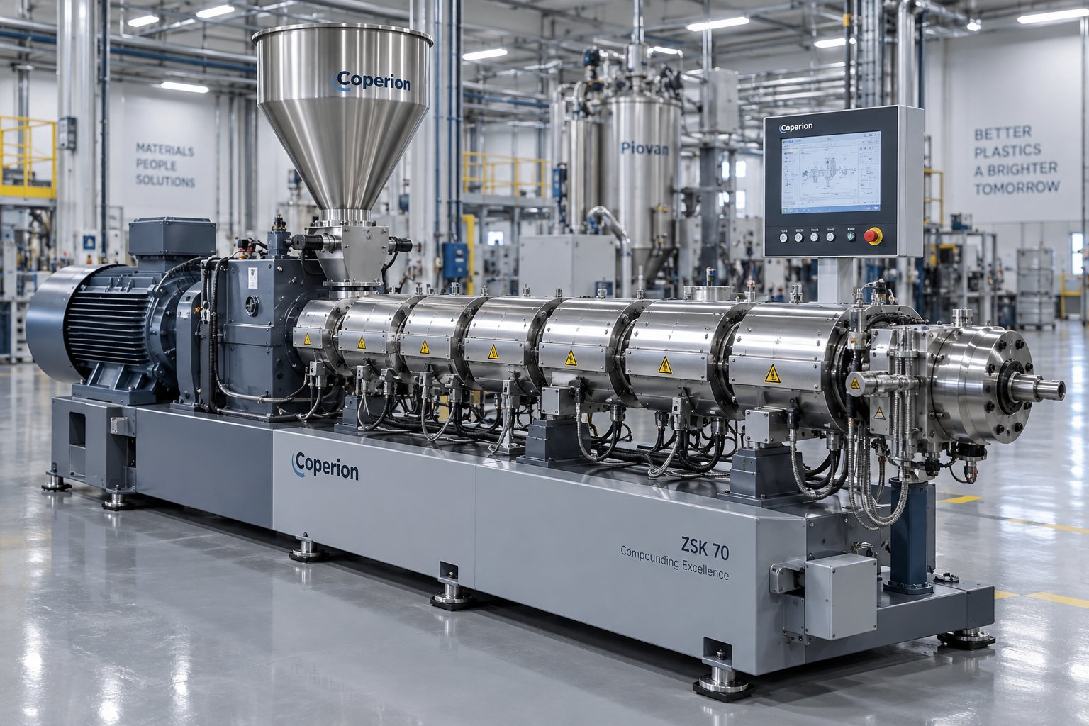
What Your Single Screw Extruder Manufacturer Won't Tell You
Oct 10, 2026
Learn how to evaluate single screw extruder manufacturers with this buyer-focused guide covering specs, configurations, material matching, and a ready-to-use selection checklist.
Read Article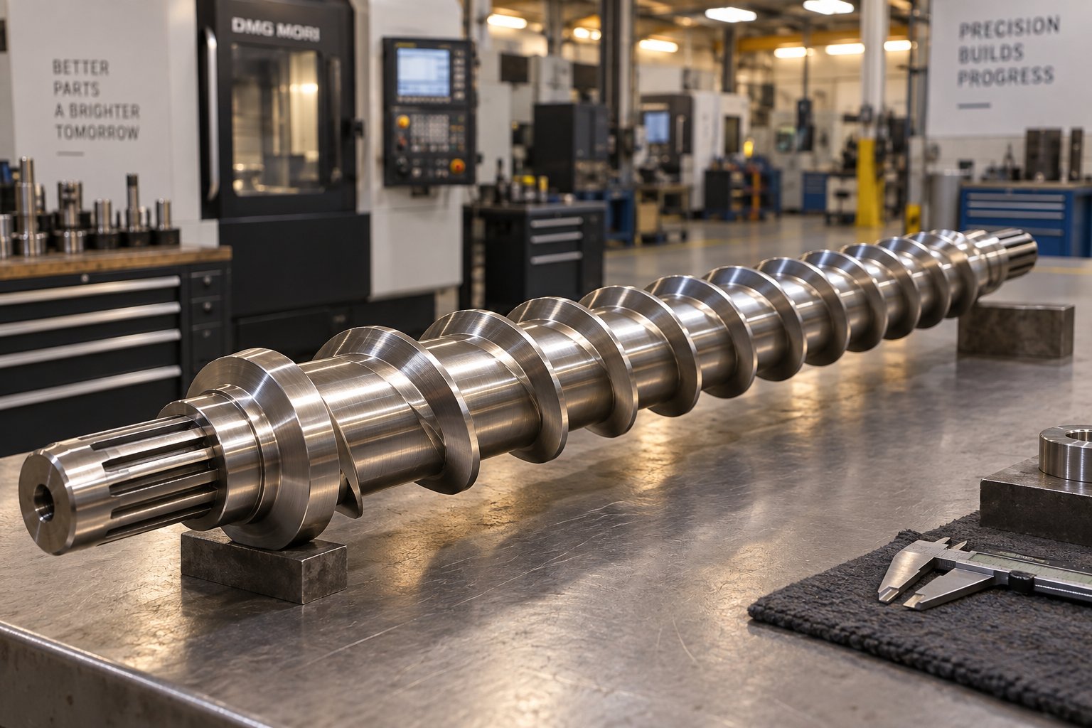
Plastic Extruder Screw Price Demystified: From Steel To Sticker
Oct 10, 2026
What drives plastic extruder screw price? This independent guide breaks down diameter, L/D ratio, metallurgy, order volume, and total cost of ownership factors.
Read Article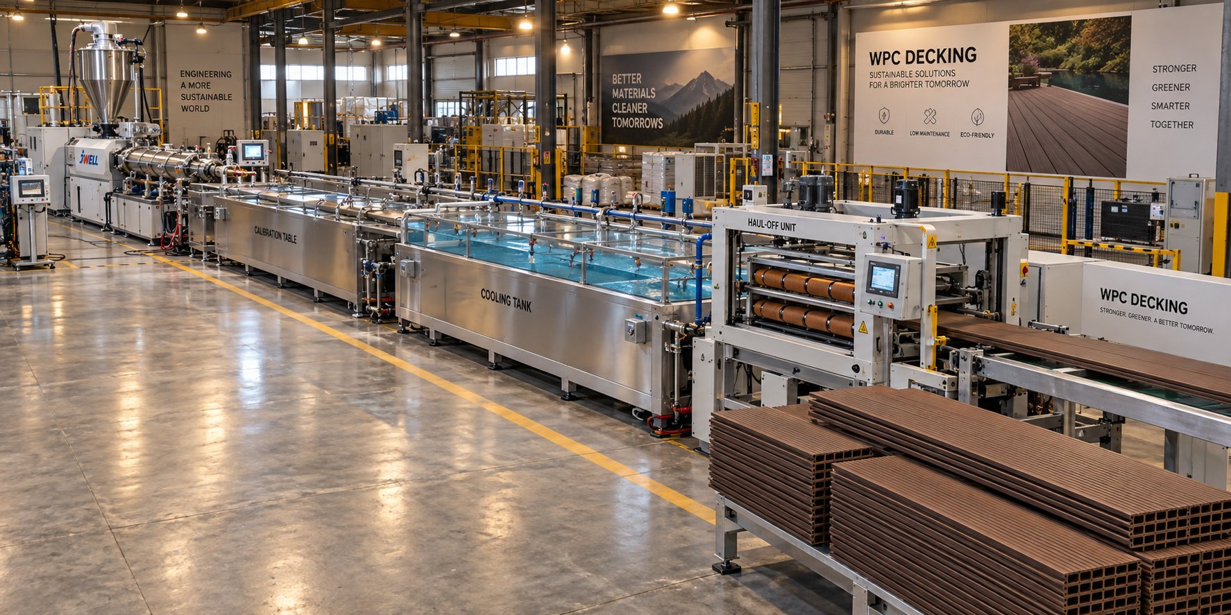
What No Supplier Tells You About WPC Decking Making Machines
Oct 6, 2026
Learn how a WPC decking making machine works, compare extruder types, formulations, and production methods, plus get a buyer checklist to evaluate any supplier.
Read ArticleLooking for something else?
Search by material, symptom or product and jump straight to the relevant page.
These are navigation suggestions based on keyword matching — not a quotation, not a delivery commitment, and not a substitute for engineering review. Final specification is confirmed by our engineers against your drawings and processed material.
Need help with screw barrel selection?
Share your machine model, processed material and application. Our team can help with pricing and technical support.