

What a Single Screw Extruder Does and Why It Leads Pellet Production
You need pellets that are uniform, dense, and consistent batch after batch. The machine most likely to deliver that outcome is also the simplest one on the factory floor. Yet most supplier pages describe this equipment in abstract terms, burying the connection between machine design and pellet quality under walls of generic specifications. This guide takes a different approach: every section is framed around the pellet you actually produce.
What Is a Single Screw Extruder and How Does It Relate to Pellets
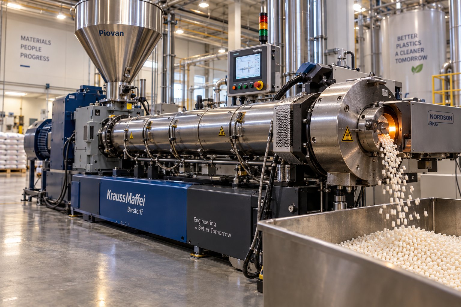
Imagine a single helical screw rotating inside a heated steel barrel. Raw material—plastic flakes, resin granules, powder, or recycled feedstock—enters through a hopper at one end. As the screw turns, it conveys that material forward, progressively melting it through a combination of barrel heat and frictional shear. By the time the material reaches the far end, it has become a homogeneous, pressurized melt ready to be pushed through a die and cut into pellets.
A single screw extruder is a continuous processing machine that uses one rotating screw inside a heated barrel to melt, mix, and pressurize raw material, then forces that melt through a die where it is cut into uniform pellets.
That straightforward mechanism is exactly what makes this technology so relevant for pellet production. Whether you are repelletizing post-consumer polyethylene, producing virgin polypropylene pellets, or creating color masterbatch, the core process remains the same: feed, melt, pressurize, extrude, and cut. The extruder handles the first four steps; a pelletizer handles the last. Together, they form the backbone of pellet manufacturing across plastics, animal feed, and biomass industries worldwide.
Why Single Screw Technology Dominates Pellet Manufacturing
With twin screw extruders and other advanced compounding systems available, why does this comparatively simple machine still account for the majority of pelletizing operations? The answer comes down to four practical advantages that matter most on a production floor:
- Mechanical simplicity. Fewer moving parts translate directly into less downtime and easier troubleshooting. A single screw system contains one screw, one drive train, and one set of bearings—making it far simpler to maintain than multi-screw alternatives.
- Lower capital cost. For operations processing standard thermoplastics like PE, PP, PS, or PVC, the initial investment is significantly lower than a comparable twin screw line, allowing faster return on investment.
- Reliable throughput. Modern screw designs optimize material transport and melting efficiency, enabling consistent high-volume output—hundreds to thousands of kilograms of pellets per hour—with minimal operator intervention.
- Ease of operation. Operator training requirements are lower, changeovers between materials are faster, and the overall learning curve is gentler, which is especially valuable for small and mid-sized pelletizing facilities.
These advantages for pelletizing make the single screw extruder the default choice when the application involves straightforward resin pelletizing, recycling repelletization, or simple additive incorporation. It handles the most common materials in global waste streams—polyethylene films, HDPE containers, polypropylene woven bags, and injection molding scrap—with proven efficiency.
Still, choosing the right extruder is only the beginning. The quality of your pellets depends on decisions that go far deeper: screw geometry, compression ratio, barrel temperature profile, die design, and downstream cutting method. Each of these factors shapes the density, surface finish, and dimensional consistency of every pellet that leaves your line—and those are exactly the details most suppliers leave out of the conversation.
How a Single Screw Extruder Turns Raw Material Into Finished Pellets
Knowing the advantages of this technology is one thing. Understanding exactly how pellets are made with a single screw extruder—from the moment raw material drops into the hopper to the instant a finished pellet rolls off the line—is something else entirely. Most supplier literature skips this walkthrough, jumping straight to specifications. That gap leaves operators and buyers guessing about what actually happens inside the machine and why it matters for their pellet quality.
Here is the single screw extruder pelletizing process step by step, broken into the stages that directly determine whether your pellets come out right or wrong.
From Hopper to Melt — Feeding, Melting, and Metering Stages
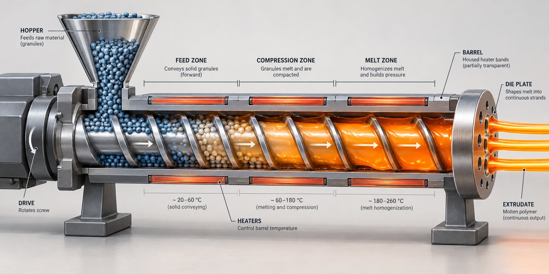
Picture raw plastic—flakes, granules, regrind, or powder—sitting in the hopper above the feed throat. Gravity pulls that material down into the barrel, where the rotating screw picks it up and begins pushing it forward. What happens next follows a precise sequence, and each stage plays a distinct role in preparing the melt for pelletizing.
- Feeding. Material drops from the hopper into the feed zone of the screw, where deep channel flights grab and convey it forward. Consistent feeding is critical here. Gravity feeding (flood feeding) keeps the screw channel full at all times, which works well for free-flowing pellets and granules. Starve feeding, where a metering feeder controls exactly how much material enters, gives you tighter control over throughput—particularly useful for powders, flakes, or materials with inconsistent bulk density.
- Melting. As the screw conveys material into the compression zone, the channel depth decreases progressively. This compacts the solid material against the heated barrel wall, creating a thin melt film. Shear friction between the screw flights and the compressing material generates additional heat. In fact, shear heating—not barrel heaters—provides the majority of melting energy for most resins. The combination of conducted barrel heat and mechanical shear work transforms the solid bed into a molten pool.
- Metering. The fully molten polymer enters the metering zone, where a uniform, shallow channel depth homogenizes the melt temperature and builds stable pressure. This pressure is what ultimately pushes the material through the die. An unstable metering zone means fluctuating die pressure—and fluctuating die pressure means pellets that vary in size, weight, and density from one second to the next.
The quality of this melt—its temperature uniformity, its freedom from unmelted particles, and its pressure stability—sets the ceiling for every pellet attribute downstream. No cutting system or cooling method can fix a poorly prepared melt.
Die Extrusion and Pellet Cutting Methods
Once the metering zone delivers a pressurized, homogeneous melt, it flows through a breaker plate (which filters contaminants and helps stabilize pressure) and into the die. The die plate contains multiple small holes that shape the melt into continuous strands or directly into pellet form, depending on the cutting method used.
This is where the three primary single screw extrusion pellet cutting techniques come into play. Each method suits different materials, production volumes, and pellet quality requirements.
Strand pelletizing is the most common method for general-purpose plastic compounding. The melt exits the die as multiple continuous strands, which pass through a water bath or water-cooled conveyor to solidify. The cooled strands then travel into a strand pelletizer, where rotating knives chop them into cylindrical pellets. This approach is straightforward, affordable, and handles a wide range of polymers. However, it typically requires manual strand threading during startup and produces slightly less uniform pellet geometry compared to other methods. Strand pelletizing works especially well for PET recycling, high-filler compounds, and materials that lack sufficient melt strength for die-face cutting.
Hot-face (die-face) cutting positions rotating blades directly against the die plate surface. The melt emerges through the die holes and is immediately sliced by the spinning knives before it can form long strands. Cooling happens after cutting—either by air blowers that carry pellets to a collection cyclone or by water that quenches the cut pellets below the die. Hot-face pelletizers offer precise control over pellet size and shape, and they eliminate the need for strand threading. The tradeoff is that the heated die plate consumes more energy, and some heat-sensitive polymers may experience slight thermal degradation at the die face.
Underwater pelletizing combines cutting and cooling into a single step. A rotating cutter head operates inside a water-filled chamber directly at the die face. The moment the melt exits the die holes, blades cut it and pressurized water instantly solidifies the pellets into near-spherical shapes. This method produces the most uniform pellets with minimal fines and dust, making it ideal for high-volume production of polyolefins and engineering resins. The tradeoff? Underwater systems demand higher capital investment and more complex maintenance than either of the other two approaches.
When comparing strand pelletizing vs underwater pelletizing methods, the decision often comes down to production scale and pellet geometry requirements. Strand systems win on simplicity and cost. Underwater systems win on pellet uniformity and throughput capacity. Hot-face cutting falls in between, offering a practical middle ground for operations that need automated startup without the full complexity of an underwater system.
How Each Stage Shapes the Final Pellet
Here is the part that most equipment descriptions miss: every upstream processing decision echoes in the finished pellet. The connection is direct, measurable, and—once you understand it—impossible to ignore.
- Melt temperature influences pellet density, surface finish, and crystallinity. Too high, and you risk thermal degradation—yellowing, black specks, or weakened mechanical properties. Too low, and the melt won't flow uniformly through the die, producing pellets with rough surfaces and inconsistent dimensions.
- Melt pressure stability at the die governs pellet weight consistency. Cyclic pressure fluctuations (surging) translate directly into pellets that alternate between heavy and light, long and short. Stable pressure from a well-designed metering zone produces pellets that weigh the same, cut after cut.
- Screw speed controls both throughput rate and shear intensity. Running faster increases output but also raises melt temperature through additional shear heating. For shear-sensitive materials, pushing speed too high degrades the polymer before it ever reaches the die—resulting in pellets that look fine on the outside but perform poorly in downstream processing.
- Die hole geometry and cutter speed determine the final pellet length, diameter, and shape uniformity. More blades or faster cutter rotation produces shorter pellets. The relationship between extrusion rate and cutter speed must stay balanced; if extrusion outpaces cutting, you get elongated pellets and tailing defects.
Think of the entire pelletizing process as a chain where every link affects the next. The feeding system determines how consistently material enters the screw. The screw's geometry controls how that material melts and pressurizes. The die and cutter transform that melt into a physical pellet. And any weakness in an upstream link—inconsistent feeding, poor melt homogeneity, unstable pressure—cascades directly into pellet defects that no amount of downstream adjustment can correct.
The natural question, then, is what exactly determines how well that screw melts and pressurizes your material. The answer lives in three specific zones inside the barrel—and the geometry of each one quietly dictates whether your pellets meet spec or miss it.
Three-Zone Screw Design and Its Impact on Pellet Quality
The previous section traced the journey of raw material from hopper to finished pellet—and at every stage, the screw's geometry was quietly running the show. But what exactly does that geometry look like inside the barrel? Most supplier spec sheets list a screw diameter and an L/D ratio, then stop. They rarely explain the internal architecture that actually determines whether your melt comes out uniform or riddled with unmelted particles.
That architecture follows a principle called feed compression metering zone screw design—three distinct regions along the screw's length, each shaped differently and each serving a specific purpose. Understanding these zones gives you the vocabulary to diagnose pellet quality problems at their source rather than chasing symptoms downstream.
Feed Zone, Compression Zone, and Metering Zone Explained
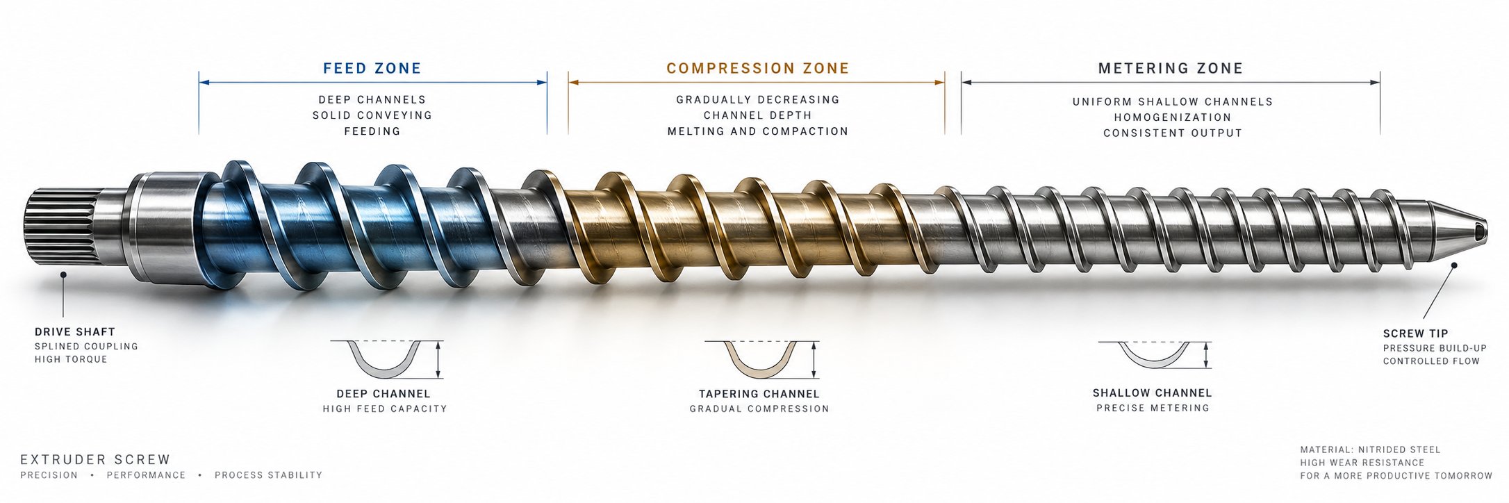
Imagine unrolling the screw from the barrel and laying it flat. You would see that the helical channel carved between the flights is not the same depth along the entire length. It starts deep, gets progressively shallower, then levels off. Those three depth profiles correspond to three functional zones, and each one handles a different stage of the material's transformation.
The feed zone sits directly beneath the hopper. Its channel is deep—intentionally so—because its job is to grab solid material (pellets, flakes, powder) and convey it forward efficiently. A deeper channel means more volume per screw turn, which maximizes the rate at which raw feedstock enters the system. No melting is expected here; the focus is purely on solid transport.
The compression zone (sometimes called the transition zone) is where the channel depth decreases gradually over several screw turns. This tapering compacts the solid material against the heated barrel wall, squeezing out trapped air and forcing intimate contact between resin particles and the hot barrel surface. The combination of compaction, barrel heat conduction, and shear friction initiates and sustains melting. As NC State Extension research notes, channel depth decreases in the order of conveying, compression, and metering zones—a deliberate progression that controls energy input into the material.
The metering zone occupies the final portion of the screw. Here the channel depth is uniformly shallow, and the material should be fully molten. This zone serves two critical functions: it homogenizes the melt temperature so that hot and cold streaks are eliminated, and it builds the stable, consistent pressure needed to push material through the die. Without a properly functioning metering zone, die pressure fluctuates—and fluctuating pressure means pellets that vary in weight and size from one second to the next.
| Screw Zone | Channel Depth | Primary Function | Effect on Pellet Output |
|---|---|---|---|
| Feed Zone | Deep (largest) | Solid conveying and intake | Determines maximum feed rate and throughput consistency |
| Compression Zone | Progressively shallower | Compaction, air removal, melting initiation | Controls melting completeness; insufficient compression leaves unmelted particles in pellets |
| Metering Zone | Uniform and shallow (smallest) | Melt homogenization and pressure generation | Governs pellet weight uniformity, surface finish, and dimensional consistency |
The screw channel depth effect on pellet quality is most visible when any one zone is mismatched to the material being processed. A feed zone that is too shallow starves the downstream sections, reducing throughput and causing erratic pressure. A compression zone that transitions too abruptly can generate excessive shear heat, degrading heat-sensitive polymers before they reach the die. A metering zone that is too deep fails to build adequate pressure, leading to inconsistent strand extrusion and ragged pellet cuts.
Compression Ratio and Channel Depth — Why They Matter for Pellets
If you could pick only one number to evaluate whether a screw is right for your pelletizing application, it would be the compression ratio. This value is simply the feed zone channel depth divided by the metering zone channel depth. A screw with a feed channel depth of 0.350 inches and a metering channel depth of 0.125 inches, for example, has a compression ratio of 2.8:1.
Sounds simple? The impact is anything but. The single screw extruder compression ratio for pellets controls how aggressively the material is compacted and sheared as it moves from solid intake to molten output. Get it right, and you produce clean, uniform pellets. Get it wrong, and you face one of two failure modes—both of which are visible in every pellet that leaves your line.
Too low a compression ratio means the feed zone does not push enough material into the metering section to keep it completely full and pressurized. The result is starved operation: low output rates, weak die pressure, and pellets that are undersized or inconsistently formed. Research conducted at Dow using a 2.5-inch diameter extruder demonstrated this clearly—a screw with a compression ratio of only 2.0 developed just 100 psi at certain measurement points, compared to 4,200-5,800 psi for screws with ratios of 2.4 and above. That pressure deficit directly translates to unreliable pellet formation at the die.
Too high a compression ratio creates the opposite problem. The feed zone is so deep relative to the metering zone that it forces more solid material forward than the compression zone can melt. Solid polymer fragments get pushed into the metering section and discharged through the die. Cross-sections of extrudate from the same Dow study showed that screws with compression ratios of 2.8 and above began discharging visible unmelted fragments at screw speeds of 110 rpm and higher. Additionally, higher compression ratios drove discharge temperatures 5 to 10 degrees Celsius higher at elevated screw speeds—meaning more thermal degradation risk and potential discoloration in finished pellets.
The optimal compression ratio depends on your specific resin. Crystalline polymers like HDPE and nylon typically require higher ratios (around 3.0:1 to 3.5:1) because their sharp melting point demands more aggressive compaction to ensure complete melting. Amorphous polymers like polystyrene or polycarbonate—and especially shear-sensitive materials like PVC—perform better with lower ratios (around 2.0:1 to 2.5:1) that apply gentler energy input. For LLDPE pellet feedstocks specifically, a compression ratio near 2.8 has been shown to be optimal for commercial extrusion, balancing throughput, melt quality, and screw wear.
The compression ratio is the single most important screw design parameter for pellet quality—it determines whether your melt exits the die fully homogenized or contaminated with unmelted fragments and thermal degradation.
Flight Geometry and Its Influence on Melt Uniformity
Beyond channel depth and compression ratio, three additional flight geometry parameters quietly shape how well your screw mixes material and builds pressure. Extrusion screw flight geometry explained in practical terms comes down to three features: flight width, helix angle, and flight clearance.
Flight width (the thickness of the helical ridge) affects the balance between conveying capacity and shear input. Wider flights reduce the open channel area available for material flow, which limits volumetric throughput. However, they also increase the contact area between the screw flight tip and the barrel wall, which can improve pressure-building capability. For pelletizing applications, most general-purpose screws use a flight width roughly equal to 10% of the screw diameter—a compromise that maximizes conveying without sacrificing too much mixing.
Helix angle (the angle of the flight relative to the screw axis) is determined by the screw pitch. A standard square-pitch screw—where the pitch equals the screw diameter—produces a helix angle of approximately 17.66 degrees. Increasing the pitch steepens the helix angle, which boosts material conveying speed but reduces residence time and shear input. Decreasing the pitch does the reverse. For pellet production, where thorough melting and mixing outweigh raw conveying speed, standard or slightly reduced pitch designs are most common.
Flight clearance is the tiny gap between the outermost edge of the screw flight and the inner barrel wall. In a new, properly manufactured screw, this clearance is typically about 0.1% of the barrel diameter. That sounds negligible, but research published in Polymers demonstrates that even small changes in flight clearance significantly influence pumping capability, power consumption, and melt temperature. As the screw wears and this gap increases, melt leaks backward over the flight tips instead of being pushed forward. The practical consequence for pelletizing is a gradual decline in output rate and melt pressure stability—both of which degrade pellet uniformity over time without any change in process settings.
Each of these flight geometry parameters interacts with the three-zone design and compression ratio to create the overall performance profile of your screw. A screw with the right compression ratio but excessive flight clearance from wear will still produce subpar pellets. A brand-new screw with perfect clearances but the wrong helix angle for your material may not provide enough mixing energy to eliminate temperature gradients in the melt.
This is precisely why understanding screw geometry matters for anyone involved in pellet production. The screw is not a generic commodity component—it is the single most influential element in your entire extrusion line. And while its geometry determines the quality ceiling for your pellets, the machine specifications surrounding it—L/D ratio, screw diameter, motor power, and barrel temperature profile—define the operational envelope in which that screw can perform.
Key Specifications That Shape Pellet Output and Consistency
Screw geometry sets the quality ceiling for your pellets, but it does not operate in isolation. Every screw sits inside a barrel of a specific length, driven by a motor of a specific power rating, surrounded by heaters set to specific temperatures. These machine-level specifications define the boundaries within which your screw can do its job—and understanding what each number actually means for pellet production is the difference between choosing the right extruder and simply buying the cheapest one that fits your floor space.
Supplier datasheets list these numbers in tidy columns. What they rarely explain is how each specification translates into pellet density, surface smoothness, or dimensional consistency. Let's bridge that gap.
L/D Ratio and What It Means for Residence Time and Melt Quality
You will see "L/D ratio" on every extruder spec sheet, often presented without context—just a number like 24:1 or 32:1. Here is what it actually tells you about your pellets.
L/D ratio is the barrel length divided by the screw diameter. A 75 mm screw inside a 2,400 mm barrel has an L/D of 32:1. That ratio controls one of the most important variables in pellet extrusion: how long your material stays inside the barrel. A longer barrel means more screw turns, more time for heat transfer and shear work, and more opportunity for the melt to reach a truly homogeneous state before it reaches the die.
For pelletizing, the practical implications break down like this:
- Longer L/D ratios (30:1 to 36:1) provide extended residence time that allows thorough melting and mixing. This is especially valuable when processing semicrystalline polymers like HDPE or nylon that demand significant energy input to fully melt. More barrel length also means more room for mixing elements or barrier sections in the screw design, which improves melt temperature uniformity. The result is pellets with smoother surfaces, more consistent density, and fewer unmelted inclusions.
- Shorter L/D ratios (20:1 to 24:1) reduce the time material spends at elevated temperatures. This matters for heat-sensitive resins like PVC or certain biodegradable polymers that degrade when exposed to prolonged thermal and shear stress. A shorter barrel also means lower capital cost and a smaller machine footprint. The tradeoff is that you have less screw length available for melting and mixing, so the screw design must be more precisely matched to the material to avoid pushing unmelted particles through the die.
As industry references note, higher L/D ratios improve melt quality but also increase pressure drop along the barrel. For pelletizing applications, that tradeoff is usually worthwhile—consistent melt quality matters more than minimizing pressure loss, because every inconsistency in the melt shows up as a defect in the finished pellet.
When deciding how to size a single screw extruder for pellets, think of L/D ratio as your budget for melt preparation. A generous budget (high L/D) gives you room for error and handles a wider range of materials. A tight budget (low L/D) demands precision in screw design and temperature control but keeps costs down for straightforward, single-resin pelletizing operations.
Screw Diameter and Motor Power — Sizing for Your Pellet Throughput
If L/D ratio governs melt quality, screw diameter governs throughput volume. The relationship between extruder screw diameter and throughput is roughly proportional to the square of the diameter—double the screw diameter, and you can expect roughly four times the volumetric output capacity (all else being equal). That scaling relationship is why small lab extruders with 20-30 mm screws produce a few kilograms per hour, while production machines with 150 mm screws push well over a thousand.
Motor power must scale alongside diameter. A larger screw requires more torque to rotate, especially when processing high-viscosity materials or running at higher compression ratios. Undersizing the motor leads to torque overload alarms, reduced maximum screw speed, and an inability to maintain the throughput rates the screw geometry was designed to deliver. For high-viscosity pelletizing applications—think recycled HDPE with contaminants or heavily filled compounds—motor sizing becomes particularly critical because the drive must overcome both the viscous drag of the melt and the mechanical resistance of compacting solids in the compression zone.
The following table presents general industry ranges for the extruder screw diameter and throughput relationship, along with typical motor power brackets. These are representative values for polyolefin pelletizing; actual performance varies with material, screw design, and L/D ratio.
| Screw Diameter | Approximate Throughput Class (PE/PP) | Typical Motor Power Range | Common Application Scale |
|---|---|---|---|
| 30-45 mm | 10-80 kg/h | 5-30 kW | Lab, pilot, low-volume specialty pelletizing |
| 50-75 mm | 50-350 kg/h | 30-110 kW | Small to mid-scale production, recycling lines |
| 90-120 mm | 200-1,000 kg/h | 90-250 kW | Full production-scale pelletizing |
| 130-150 mm | 600-2,000+ kg/h | 200-500+ kW | High-volume resin producers, large recycling plants |
These ranges align with manufacturer-rated capacity data for standard single screw extruders processing polyolefins. Notice that the throughput ranges overlap between diameter classes. That overlap reflects the influence of L/D ratio, screw speed, and screw geometry—a well-designed 75 mm screw at 30:1 L/D can sometimes match the output of a poorly optimized 90 mm machine.
When sizing your extruder, resist the temptation to simply buy the largest diameter your budget allows. A bigger screw produces more pellets per hour, but it also means higher energy consumption, longer heat-up times, more material wasted during startup and color changes, and greater capital expenditure. Match the diameter to your actual production volume target, then select the L/D and screw design that deliver the melt quality your pellet application demands.
Temperature Profile Configuration for Pellet Consistency
You have the right screw diameter, the right L/D ratio, and a properly designed compression ratio. Can you still produce bad pellets? Absolutely—if your barrel temperature profile is wrong.
The barrel is divided into individually controlled heating zones, typically three to six depending on barrel length. Each zone has its own heater bands and thermocouple, and each one needs to be set to a temperature that supports what the material is doing at that specific location along the screw. Setting all zones to the same temperature is one of the most common mistakes in pellet extrusion, and it almost always produces suboptimal results.
Here is why the barrel temperature profile for pellet extrusion matters zone by zone:
- Zone 1 (feed section). This zone is the most misunderstood. As extrusion expert Jim Frankland explains, setting Zone 1 too far below the polymer's melting point delays melt film formation and effectively shortens the melting length of the screw—reducing output. Setting it too far above the melting point lowers viscosity at the barrel wall, which reduces the frictional drag that drives solids conveying and actually slows the melting rate. A good starting point is a temperature slightly above the polymer's melting point—warm enough to initiate the melt film without eliminating the friction that moves material forward.
- Mid-barrel zones (compression section). Temperatures here should support the transition from solid to melt. Gradually increasing setpoints through the compression zone help the melt film develop progressively, matching the channel depth reduction in the screw. Abrupt temperature spikes can create localized overheating and degradation; temperatures set too low force the screw to do all the melting work through shear alone, which raises mechanical energy input and can overheat the melt from the inside out.
- End zones (metering section). These zones fine-tune the final melt temperature before the die. For most pelletizing operations, the goal is a stable melt temperature that produces uniform flow through every die hole. Overheating in the metering section causes thermal degradation—yellowing, off-gassing, or reduced mechanical properties in the finished pellets. Underheating produces a stiffer melt that may not fill all die holes evenly, leading to inconsistent pellet diameters.
One principle ties all of this together: barrel heaters are not the primary energy source for melting. The drive motor, working through the screw, provides the majority of the energy through shear and friction. Barrel heaters primarily serve to initialize melting, prevent excessive cooling at the barrel wall, and trim the temperature profile. That is why experienced operators often find their barrel heaters cycling off during steady-state production—the mechanical energy from the screw is doing the heavy lifting.
Getting the temperature profile right is part science and part iteration. Start with the resin manufacturer's recommended processing range, set a gentle ramp from Zone 1 through the metering section, then monitor melt temperature and pressure at the die. Stable pressure readings and consistent pellet appearance confirm you are in the right range. Cyclic pressure swings, surface roughness, or discoloration tell you the profile needs adjustment.
These specifications—L/D ratio, screw diameter, motor power, and temperature profile—form the operational envelope that determines your extruder's capability. But capability alone does not answer the question every buyer eventually faces: is a single screw extruder actually the right choice for my specific pelletizing application, or would a twin screw system serve me better? That comparison deserves an honest, pellet-focused analysis rather than the vague generalities most suppliers offer.
Single Screw vs Twin Screw Extruder for Pellets: An Honest Comparison
Every extruder salesperson has a preference. Single screw suppliers emphasize simplicity and cost. Twin screw suppliers emphasize mixing and flexibility. What neither side typically does is lay out the exact boundary conditions—framed around your pellet application—where one technology genuinely outperforms the other. That lack of transparency costs buyers real money, either through overspending on capability they do not need or underbuying and discovering the limitation mid-production.
This section draws that line clearly. No hedging, no vague qualifiers. If a single screw extruder handles your pelletizing job well, you should know exactly why. If it does not, you should know that too—before you sign a purchase order.
Where Single Screw Extruders Excel in Pellet Production
For the majority of pelletizing operations worldwide, a single screw system is not just adequate—it is the best extruder type for plastic pellet production in those specific scenarios. The reasons are both technical and economic, and they compound in favor of single screw technology when your application falls within its natural strengths.
Straightforward resin pelletizing is the most obvious fit. When you are converting virgin polyolefins (PE, PP), polystyrene, or similar commodity resins from reactor powder or fluff into finished pellets, the material is clean, consistent, and does not require intensive distributive mixing. The single screw extruder's conveying channel melts, homogenizes, and pressurizes this material efficiently, and the resulting pellets meet commercial specifications with minimal process complexity.
Recycling and repelletizing of clean regrind is another natural strength. Post-industrial scrap—edge trim from film lines, runner material from injection molding, off-spec production—is typically a single polymer with known properties. As industry comparisons confirm, single screw extruders perform best when the material stream is stable and predictable: clean post-industrial scrap, uniform films, or rigid plastics with low moisture and low contamination. In these scenarios, the machine delivers reliable output at lower operating costs than any twin screw alternative.
Simple color or additive masterbatch at low loading levels also falls squarely within single screw capability. Adding 1-5% pigment concentrate or a small percentage of UV stabilizer to a carrier resin does not demand the intensive kneading that a twin screw provides. A single screw with a mixing section—a Maddock mixer, pineapple mixer, or similar dispersive element—distributes these low-concentration additives effectively enough for most commercial pellet specifications.
General-purpose compounding pellets with minimal filler round out the list. If your formulation involves a base resin with less than roughly 20-30% of an easy-to-disperse filler like calcium carbonate, and the end-use tolerances are not extreme, a single screw extruder handles the job with several practical advantages over twin screw systems:
- Capital cost savings of 40-60% compared to a twin screw line of similar throughput capacity, due to simpler gearbox, single drive train, and less complex barrel construction.
- Lower energy consumption per kilogram of pellets for comparable materials, because a single screw's simpler drive mechanism and lower frictional losses consume less power. As technical comparisons note, under the same production capacity, single screw extruders are usually more energy-efficient due to their simpler structure and higher frictional heat generation efficiency.
- Simpler operation and faster training. Operators learn to run single screw lines in days rather than weeks. Changeovers between materials are faster. There are no modular screw element configurations to redesign for different formulations.
- Better wear resistance to hard contaminants. The larger clearance between screw and barrel and the robust single-flight structure make these machines less sensitive to occasional hard impurities—a practical advantage for recycling operations where feedstock quality can vary.
For any pelletizing application that fits within these boundaries, choosing a twin screw extruder means paying more for capability you will never use. That is money better spent on downstream equipment, quality control, or additional production capacity.
When Twin Screw or Alternative Technology Becomes Necessary
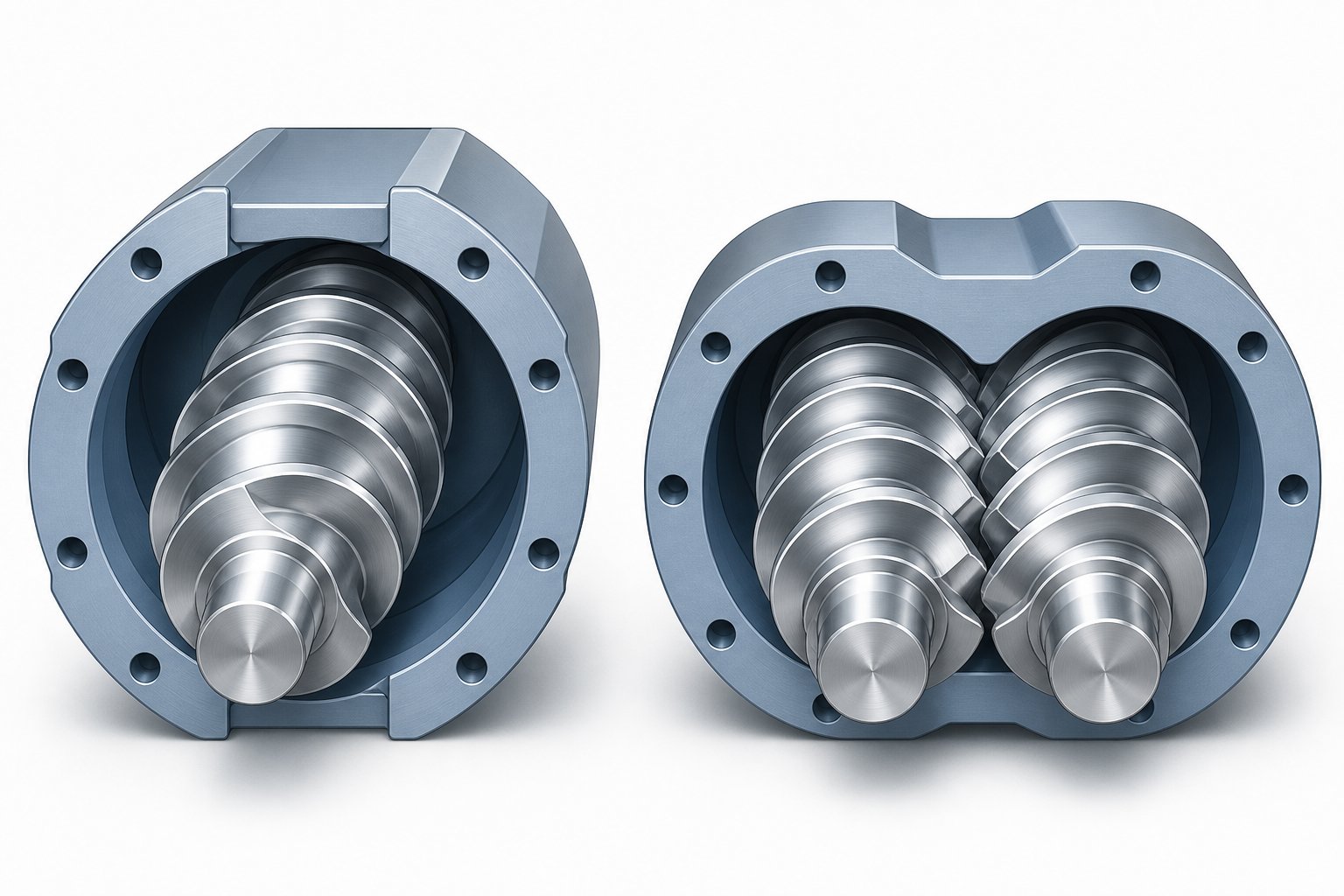
Here is where honesty matters most. A single screw extruder has a fundamental architectural limitation: it relies on a single conveying channel to transport, melt, mix, and pressurize material simultaneously. That channel cannot provide the intensive distributive mixing, staged feeding flexibility, or strong devolatilization that certain pellet applications demand. Pretending otherwise leads to production problems that no amount of screw optimization can fully resolve.
The boundary conditions are specific and worth stating directly:
High filler loading above approximately 40-50%. When your pellet formulation calls for heavy mineral filler, glass fiber reinforcement, or flame retardant loadings in this range, the filler must be uniformly wetted, dispersed, and distributed throughout the polymer matrix. A single screw's limited mixing action cannot achieve the dispersion quality that a twin screw extruder's intermeshing, self-wiping elements deliver. The result with a single screw? Pellets with filler agglomerates, inconsistent mechanical properties, and visible quality issues.
Reactive extrusion. Processes like grafting maleic anhydride onto polyolefins, in-situ polymerization, or peroxide-initiated crosslinking require precisely controlled residence time, temperature, and mixing intensity. A twin screw extruder allows operators to configure screw elements for specific reaction zones, control fill level independently of screw speed, and place side-feeding or liquid injection ports at exact locations along the barrel. A single screw simply does not offer this level of process section control.
Complex multi-component blends. Imagine blending two polymers with vastly different melt viscosities—say, a low-MFI HDPE with a high-MFI PP—into a uniform alloy pellet. The rheological mismatch means one component melts and flows freely while the other is still solid or highly viscous. Twin screw extruders handle this through repeated kneading and folding action that breaks the minor phase into fine domains. A single screw extruder, with its single-channel flow path, produces a poorly mixed melt that yields pellets with visible phase separation or wildly inconsistent properties.
Materials requiring intensive degassing. Post-consumer recycled plastics contaminated with moisture, printing inks, adhesive residues, or volatile organic compounds need vacuum devolatilization to produce clean pellets. While single screw extruders can incorporate vented barrel sections, their limited melt surface renewal means they remove volatiles far less effectively than twin screw systems, which continuously expose fresh melt surfaces through their intermeshing screw action.
Extremely tight pellet property tolerances. Engineering compound pellets destined for automotive, medical, or electronic applications often require mechanical properties controlled within narrow windows. The superior melt homogeneity and process control flexibility of a twin screw extruder—improved melt homogeneity, more stable pressure and temperature control, and reduced risk of unmelted particles—make it the safer choice when rejection costs are high and specifications are unforgiving.
Ignoring these boundary conditions does not save money. It costs money—in scrap rates, customer rejections, and eventual equipment replacement when the single screw line cannot meet quality targets.
A Decision Framework for Choosing the Right Extruder Type
Rather than memorizing specification tables, use this practical framework the next time you evaluate whether a single screw extruder fits your pelletizing application. Walk through each condition. If your situation matches the left column, single screw technology is likely the right call. If you land in the right column, investigate twin screw options before committing capital.
- Your feedstock is a single polymer or clean blend of compatible polymers → single screw is likely sufficient. Your feedstock involves incompatible polymer blends requiring compatibilization → evaluate twin screw.
- Additive or filler loading stays below 20-30% → single screw handles dispersion adequately with a mixing section. Filler loading exceeds 40%, or you are incorporating glass fiber, carbon fiber, or difficult-to-disperse flame retardants → twin screw with side feeding is the more reliable path.
- Your material is dry, clean, and has low volatile content → single screw works without extensive degassing. Your material contains significant moisture, printing inks, adhesive residues, or solvents requiring vacuum removal → twin screw devolatilization provides superior volatile extraction.
- Your pellet application has standard commercial tolerances for mechanical properties and appearance → single screw meets specification consistently. Your pellet application demands tight-tolerance engineering compound properties with batch-to-batch traceability → twin screw process control offers the consistency margin you need.
- Your production involves one or a few similar materials with infrequent formula changes → single screw simplicity and fast changeover are advantages. Your production requires frequent formula changes, staged ingredient addition, or R&D-scale process flexibility → twin screw modular design adapts more efficiently.
- Budget optimization is a priority and your material fits within the constraints above → single screw delivers the best return on investment. Long-term ROI through reduced scrap, higher pellet quality, and material versatility justifies higher initial cost → twin screw pays for itself over time in complex applications.
A useful rule of thumb from practical extrusion technology guidance puts it this way: single screw extrusion is often best after the formula is already right; twin screw extrusion is often best when the formula still needs to be created, modified, mixed, degassed, or controlled. If the material entering your hopper is already a well-defined, well-prepared feedstock, a single screw extruder converts it into pellets more economically than anything else on the market. If that material still needs to be built into a compound, the twin screw's mixing architecture earns its higher price.
The most advanced recycling operations have recognized this division clearly. Many modern recycling lines now use a two-stage system: a single screw extruder with a large L/D ratio for pre-melting and coarse filtration as the first stage, followed by a twin screw extruder for deep degassing and fine modification as the second. This hybrid approach captures the cost efficiency and robust material handling of single screw technology while leveraging twin screw mixing and devolatilization where it adds genuine value.
Whichever technology you choose, the purchase price on the invoice is only the beginning of the cost story. Energy consumption, labor requirements, maintenance schedules, and hidden downtime expenses shape the true economics of running a pelletizing line—and those operating costs deserve the same level of scrutiny as the machine selection itself.
Operating Costs and Economics of Single Screw Pellet Extrusion
The invoice price of your extruder is the most visible number in the entire purchase decision—and one of the least representative of what you will actually spend. Industry-wide TCO research shows that acquisition cost typically represents just 25-35% of total lifecycle expense for industrial equipment, with the remaining 65-75% hiding in energy bills, maintenance budgets, labor overhead, and production loss reports. For a single screw pelletizing line running two shifts a day, five days a week, those operational dollars quietly dwarf the original capital outlay within the first few years.
Understanding the total cost of ownership for single screw extrusion is what separates a smart equipment investment from an expensive lesson. Here is where the real money goes.
Capital Investment and Price Considerations by Capacity Class
What drives single screw extruder price factors and cost drivers? It is not a single specification—it is the interplay of several design parameters that scale together.
Screw diameter is the most influential variable. A larger screw requires a heavier barrel, a bigger gearbox, higher-capacity thrust bearings, and a more powerful motor. Each of these components adds material cost and machining complexity. L/D ratio compounds the effect: stretching from 24:1 to 32:1 on the same screw diameter adds barrel sections, heater bands, and additional screw length—all of which increase both manufacturing and shipping costs.
Motor power tracks screw size closely. As industry data indicates, single screw extruders typically require 0.5 to 1.5 kW per kg/h of output capacity—meaning a machine rated for 300 kg/h may carry a 150-450 kW drive depending on the viscosity of the material being pelletized. Higher power ratings translate directly to larger electrical infrastructure and higher equipment cost.
Control system sophistication creates a surprising spread within the same diameter class. A basic analog-controlled extruder with manual temperature setpoints costs significantly less than a machine equipped with PLC-based controls, touchscreen HMI, data logging, and closed-loop pressure feedback. For pelletizing operations requiring batch traceability or tight process documentation, the advanced controls are not optional—but they do move the price upward.
Build quality and metallurgy affect both price and long-term economics. Nitrided barrels cost less upfront than bimetallic-lined barrels, but they wear faster when processing abrasive materials like glass-fiber-filled compounds or contaminated recycled feedstock. Choosing the cheaper barrel saves capital today and costs more in replacement frequency tomorrow.
In general terms, entry-level single screw extruders suitable for basic pelletizing start in the range of $30,000 to $80,000, mid-range production models fall between $80,000 and $200,000, and industrial-scale systems with advanced features can range from $200,000 to $500,000 or higher. Compare that to twin screw systems for similar throughput, which typically start at $150,000 and can exceed $1,500,000—and the capital advantage of single screw technology becomes immediately clear for applications within its capability.
Energy Consumption and Per-Kilogram Operating Costs
After you have paid for the machine, energy becomes the largest recurring line item. Understanding the energy consumption of a single screw pelletizing line requires looking beyond the motor nameplate to the full system.
The drive motor is the dominant energy consumer. It provides the torque that rotates the screw, and since screw-driven shear generates the majority of the melting energy, the motor effectively funds both material transport and thermal processing. Barrel heaters contribute a smaller share—primarily during startup and for fine-tuning the temperature profile during steady-state operation, when shear heating carries most of the load. Cooling systems (barrel cooling fans, strand cooling water baths, underwater pelletizer water circuits) and downstream equipment (pelletizers, conveyors, classifiers, dryers) collectively account for an additional 20-30% of total line energy consumption, a proportion consistent with auxiliary equipment energy data across extrusion systems.
For the single screw extruder operating cost per kg, industry benchmarks place specific energy consumption at approximately 0.15 to 0.25 kWh per kilogram of processed material for standard polyolefin pelletizing. That range shifts depending on resin viscosity, screw design efficiency, and throughput rate relative to machine capacity. Running an extruder well below its rated throughput increases specific energy consumption because the motor and heaters still draw baseline power even when producing fewer pellets per hour.
This is where screw design directly affects your electricity bill. A properly matched compression ratio minimizes wasted mechanical energy—too low a ratio means the motor works hard to push material through an underfilled metering zone, while too high a ratio forces the drive to overcome excessive compaction resistance. An optimized L/D ratio ensures the material reaches full melt within the available barrel length rather than relying on elevated barrel heater setpoints to compensate for incomplete shear melting. Both inefficiencies show up as higher kWh per kg of finished pellets.
Compared to twin screw alternatives, single screw systems generally consume less energy per kilogram for comparable materials. Twin screw extruders typically run at 0.2 to 1.0 kWh per kilogram, with the higher end reflecting intensive compounding operations. For straightforward pelletizing of clean resin or recycled feedstock, the single screw extruder's simpler drive mechanism and efficient frictional heat generation translate into measurably lower energy costs per ton of output.
Labor, Downtime, and Hidden Cost Factors
Energy costs are at least visible on a utility invoice. Labor, downtime, and changeover losses often slip through cost tracking entirely—yet they can equal or exceed energy expenses over a machine's lifetime.
Operator skill requirements are genuinely lower for single screw pelletizing lines compared to twin screw systems. The process involves fewer adjustable parameters: screw speed, barrel temperature zones, and cutter speed. Twin screw operations demand deeper understanding of screw element configuration, side-feeder coordination, and complex zone-by-zone process interactions. This difference translates into lower wage requirements, shorter training periods, and easier shift coverage for single screw operations.
Changeover time between materials—purging the barrel, cleaning the die plate, adjusting temperatures—tends to be faster on single screw lines because there is one screw to purge instead of two intermeshing screws with intricate element geometries. For operations that switch between resin grades or colors multiple times per week, changeover efficiency directly affects annual throughput.
Unplanned downtime is the most expensive hidden cost in any pelletizing operation. Single screw extruders typically achieve availability rates of 92% to 96% with proper maintenance—higher than the 88-94% range commonly seen with twin screw systems. Each percentage point of availability translates to roughly 50 additional production hours per year on a 5,000-hour operating schedule. Multiply that by your per-hour pellet output value, and the financial impact becomes clear.
A well-structured TCO framework captures all of these cost streams in one lifecycle view. For a mid-range 75 mm single screw pelletizing system, 10-year ownership costs—including acquisition, energy, labor, maintenance, and downtime—typically fall in the range of $1.68 million to $2.4 million. The initial purchase price represents a fraction of that total. Here is a breakdown of the primary cost categories to track:
- Capital acquisition: purchase price, delivery, installation, commissioning, and initial operator training
- Energy: drive motor electricity, barrel heater consumption, cooling system power, downstream equipment draw
- Labor: operator wages, shift coverage, training and skill development costs
- Maintenance and wear parts: screw and barrel replacement, die plate refurbishment, gearbox servicing, thrust bearing replacement
- Consumables: lubricants, heater bands, thermocouples, screen packs, purge compound
- Downtime losses: unplanned stoppages, planned maintenance shutdowns, changeover purging time
- Material waste: startup scrap, purge material, off-spec pellets during process stabilization
Tracking each category separately reveals where your real cost leverage lies. In most single screw pelletizing operations, energy optimization and preventive maintenance deliver the largest returns—because they reduce both direct expenses and the cascade of production losses that follow an unplanned breakdown.
That brings up a question most operators only ask after pellet quality starts slipping: what does wear actually look like inside the barrel, how fast does it progress, and at what point does it start costing you more in lost output and defective pellets than the replacement components would cost to install?
Maintenance and Wear Management for Consistent Pellet Output
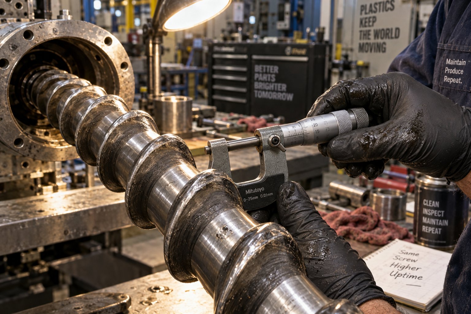
Wear inside your extruder barrel does not announce itself with alarms or flashing lights. It shows up quietly—in pellets that gradually lose weight consistency, in output rates that drift downward over months, in surface finishes that slowly roughen without any change to your process settings. By the time most operators notice the problem, the screw and barrel have already been losing performance for thousands of production hours. Understanding single screw extruder barrel and screw wear signs before they reach that stage is what separates a well-managed pelletizing line from one that hemorrhages money through scrap and unplanned shutdowns.
Screw and Barrel Wear Patterns That Degrade Pellet Quality
Three distinct wear mechanisms attack extruder internals, and each one leaves different evidence on the metal surfaces. Recognizing which type is at work tells you not just that components need attention, but why they are wearing—and what to do about it.
Abrasive wear is the most common culprit in pelletizing operations. Every hard particle in your feedstock—glass fiber, calcium carbonate, titanium dioxide, talc, or metal contaminants in recycled material—acts like microscopic sandpaper against the barrel bore and screw flights. The sharp machined edges of screw flights gradually round off and polish smooth, while the barrel bore slowly enlarges. Industry experience confirms that the severity depends on three interacting factors: the materials of construction for the barrel and screw, screw speed and throughput rate, and the abrasive characteristics of the formulation being processed. This makes abrasive wear proportional to the amount of material produced rather than the calendar time the extruder has been running—a distinction that matters when you schedule inspections.
Adhesive wear occurs when metal-to-metal contact happens between the screw flight tips and the barrel wall. In a properly functioning extruder, a thin film of molten polymer separates these surfaces. But during startup, shutdown, or operation with insufficient material in the barrel, that protective film disappears. The result is direct metal rubbing that flattens screw flight crests and scores the barrel bore. You will notice flattened flight tips and longitudinal scratches inside the barrel—telltale signs that the screw has been deflecting under load or running without adequate melt support.
Corrosive wear is a chemical attack. Processing PVC releases hydrochloric acid at elevated temperatures. Flame retardants containing halogenated compounds generate similarly aggressive byproducts. Certain fluoropolymers emit hydrofluoric acid under shear. These chemicals eat into the metal surface, creating a pitted, dimpled appearance that is distinctly different from the smooth erosion of abrasion or the scratch marks of adhesion. Corrosive wear accelerates dramatically when combined with either of the other two mechanisms—the chemical attack removes protective surface layers, exposing fresh metal to abrasive or adhesive damage at an accelerated rate.
Here is the critical link to pellet quality that most maintenance discussions overlook: all three wear types increase the clearance between the screw flight outer diameter and the barrel inner wall. In a new extruder, that gap is typically around 0.1% of the barrel diameter. As it grows, molten polymer leaks backward over the flight tips instead of being pushed forward toward the die. The consequences are immediate and measurable:
- Reduced output rate at the same screw speed, because a growing percentage of the melt recirculates rather than advancing
- Pressure instability at the die, causing cyclic surging that produces pellets alternating between oversize and undersize
- Inconsistent pellet weight, because the volume of melt delivered per screw revolution becomes unpredictable
- Increased melt temperature, as backward-flowing polymer absorbs additional shear energy without contributing to throughput—potentially causing thermal degradation visible as yellowing or black specks in pellets
The insidious part? These changes are gradual. Operators compensate by nudging screw speed upward, adjusting temperatures, or tweaking cutter timing—masking the root cause until performance degrades beyond adjustment range. Systematic measurement is the only reliable way to catch wear before it reaches that point.
Preventive Maintenance Schedules for Pelletizing Lines
A preventive maintenance schedule for a pelletizing extruder is not about following a rigid calendar. It is about establishing a measurement rhythm that tracks wear trends before they become production problems. The goal, as practical extrusion maintenance frameworks emphasize, is converting hidden drift into planned work—scheduling repairs before failures force the schedule for you.
The following checklist provides a general maintenance framework for the critical wear-related components in a single screw pelletizing line. Frequencies should be adjusted based on your specific material abrasiveness, operating hours, and production intensity.
| Component | Inspection Type | General Frequency Guideline | What to Look For |
|---|---|---|---|
| Screw flights | Pull screw and measure outer diameter at feed, compression, and metering zones | Every 2,000-4,000 operating hours (more frequently with abrasive materials) | Diameter reduction exceeding 0.1-0.15 mm per side from original specification; rounding of flight edges |
| Barrel bore | Bore gauge measurement at feed, compression, and metering sections | Every 2,000-4,000 operating hours, coordinated with screw pull | Bore enlargement beyond manufacturer tolerance; ovalization; pitting or scoring |
| Die plate | Visual inspection of die holes and land surfaces; dimensional check of hole diameters | Every material changeover or weekly during continuous runs | Hole erosion, buildup on land surfaces, cracking, uneven flow distribution |
| Gearbox oil | Oil level check and color inspection; send sample for lab analysis | Level check weekly; oil analysis every 3-6 months | Dark discoloration, metallic particles, foaming, or water contamination indicating internal wear |
| Thrust bearing | Monitor axial play; listen for abnormal noise under load | Monthly check; detailed inspection during scheduled shutdowns | Increased axial movement, unusual vibration patterns, elevated bearing temperature |
| Barrel heaters and thermocouples | Check terminal tightness, wiring condition, and zone temperature accuracy | Weekly terminal inspection; thermocouple calibration every 6-12 months | Loose or corroded terminals, cracked ceramic heater bands, temperature reading drift |
| Feed throat cooling | Verify coolant flow rate and outlet temperature | Daily during production | Reduced flow indicating scale buildup; elevated outlet temperature suggesting partial blockage |
The most valuable data point in this entire checklist is the trend line, not the individual reading. A single measurement of screw diameter tells you the current state. Three measurements taken at regular intervals tell you the rate of wear—and that rate lets you predict when to replace the screw and barrel before pellet quality collapses. As maintenance data practices recommend, if screw clearance, melt pressure, or gearbox temperature moves in the wrong direction for two or three consecutive readings, schedule the repair before the line forces your hand.
A practical rule of thumb for knowing when to replace extruder screw and barrel components: when the screw flight outer diameter has worn down by approximately 5% from its original dimension over three-quarters of the element length, or when the barrel bore has enlarged by a comparable percentage over a length of one diameter, the resulting clearance increase has likely reached the point where output loss, pressure instability, and pellet quality degradation exceed the cost of replacement parts. Waiting beyond that threshold typically means you are paying for the new components anyway—just through scrap, energy waste, and lost production rather than a planned purchase order.
Choosing Quality Replacement Barrels and Screws
When the measurement data confirms it is time for replacement, the metallurgy of the new components becomes the most important purchasing decision you will make. A replacement barrel or screw built from the wrong material for your application will wear right back to the same condition in a fraction of the expected service life—costing you a second replacement, a second production shutdown, and a second round of quality problems in between.
Three metallurgical approaches dominate the replacement market, and each targets a different wear environment:
Nitrided steel barrels and screws represent the baseline. The nitriding process diffuses nitrogen into the steel surface, creating a hard case layer that resists moderate abrasive and adhesive wear. For operations pelletizing unfilled or lightly filled virgin resins—standard PE, PP, PS—nitrided components provide adequate service life at the lowest component cost. However, they reach their limit quickly when processing glass-fiber-reinforced compounds, heavily filled masterbatch, or contaminated post-consumer recyclate.
Bimetallic barrels are the workhorse solution for abrasive pellet extrusion. A bimetallic barrel for abrasive pellet extrusion combines a structural steel outer shell with a centrifugally cast inner liner of wear-resistant alloy—typically a chromium-nickel, iron-based, or tungsten-carbide-enriched formulation. The liner thickness generally ranges from 1 mm to 2 mm, and the metallurgical bond between liner and shell ensures structural integrity under operating pressures and temperatures. The performance difference is substantial: bimetallic barrels can deliver 3 to 7 times higher abrasion resistance than standard nitrided barrels, depending on the alloy grade selected. For pelletizing lines processing calcium carbonate-filled compounds, glass-fiber masterbatch, or recycled material with hard contaminants, the higher upfront cost of a bimetallic barrel pays for itself through dramatically extended service intervals and fewer production interruptions.
Specialized coatings and alloy overlays address corrosive wear environments. When processing PVC, halogenated flame retardants, or fluoropolymers, the inner barrel surface needs chemical resistance in addition to hardness. Nickel-alloy liners or chromium-nickel overlays resist the acid attack these materials generate during processing, maintaining smooth bore surfaces that would rapidly deteriorate in a standard nitrided or even a standard bimetallic barrel.
Matching the liner alloy to your dominant wear mechanism is essential. An abrasion-resistant carbide liner will not protect against hydrochloric acid from PVC processing. A corrosion-resistant nickel-alloy liner will not hold up against glass-fiber abrasion. Specify the component based on your actual production material—not on a generic catalog recommendation.
Beyond metallurgy, dimensional precision matters just as much. The gap between screw and barrel is typically on the order of 1/1000 of the diameter. A replacement barrel or screw machined outside that tolerance starts its service life with the same clearance problems you just replaced the old components to fix. This is why sourcing from manufacturers who specialize in extrusion screw and barrel production—rather than general machining shops—makes a measurable difference in installed performance.
For readers who need to source replacement single screw barrels for pelletizing or recycling lines, NANHAIYA offers custom-engineered barrels with metallurgical specifications matched to specific extrusion applications—including nitrided, bimetallic, and specialty-alloy configurations for pipe, film, sheet, pelletizing, and general-purpose lines. Their focus on application-specific barrel design makes them a practical resource when you need components that match both your material requirements and your dimensional tolerances, rather than settling for off-the-shelf replacements that may not align with your pelletizing screw geometry.
Replacing worn components restores your extruder to its original performance envelope. But what happens when pellet defects appear even on a well-maintained machine? Inconsistent pellet size, surface roughness, discoloration, and unmelted particles can all trace back to process conditions rather than wear—and diagnosing those problems requires a different kind of troubleshooting altogether.
Troubleshooting Common Pellet Defects on a Single Screw Extruder
A well-maintained extruder with fresh components can still produce defective pellets. Worn screws and barrels are not the only villains—process conditions, feedstock quality, and temperature settings create their own catalog of problems. The difference between experienced operators and everyone else is a systematic diagnostic approach: name the defect, trace it upstream to its origin, and make one controlled correction at a time. As practical extrusion troubleshooting frameworks emphasize, stacking multiple changes simultaneously makes the real cause harder to identify and often introduces new instability.
Here are the pellet defects you are most likely to encounter on a single screw pelletizing line—and the diagnostic logic that gets you to the root cause before you waste hours chasing symptoms.
Inconsistent Pellet Size and Surging Problems
You notice pellets alternating between long and short, heavy and light, in a rhythmic cycle. That pattern almost always traces back to melt pressure fluctuation at the die—a condition known as surging. When die pressure oscillates, the volume of melt pushed through each die hole per cutter revolution changes, and every cycle produces pellets of a different length and weight.
What causes surging? The single screw extruder pellet size inconsistency causes break down into four primary categories, and each one requires a different diagnostic path:
- Inconsistent solids conveying. This is the most common root cause. As Mark Spalding of Dow documents, improper temperatures in the solids conveying section are the most likely trigger for flow surging in smooth-bore extruders. A feed casing that runs too hot—due to mineral-occluded cooling channels or insufficient water flow—reduces the frictional grip the barrel wall needs to push solids forward. The result is cyclic feeding: material moves forward in bursts rather than continuously, creating pressure waves that propagate all the way to the die.
- Hot screw in the feed section. If the screw root temperature in the first several diameters rises too high, solids stick to the screw instead of sliding along it. That reverses the force balance needed for steady conveying. Spalding's documented case involved an 8-inch two-stage extruder that ran stably for 400 minutes before surging began—the root cause turned out to be a screw cooling hole that was three diameters too short to cool the full solids conveying section. Extending the cooling hole and adding a water pump eliminated the surging permanently.
- Worn screw and barrel. Increased flight clearance from wear allows melt to leak backward over the flight tips, reducing the net forward flow. This leakage is pressure-dependent—it increases when backpressure rises and decreases when it drops—creating a self-sustaining oscillation that appears as cyclic surging.
- Moisture in feedstock. Hygroscopic resins like nylon or PET that are not adequately dried release steam in the compression zone, creating gas pockets that disrupt the continuous solid bed. The resulting intermittent feeding produces irregular pressure pulses at the die.
The diagnostic approach for how to fix surging in single screw extrusion follows a specific priority. First, check your pressure transducer output for cyclic variation—if the pressure trace shows regular oscillations, surging is confirmed. Second, touch the feed casing: it should feel warm, never hot. A hot feed casing suggests cooling channel blockage. Third, if screw cooling is used, verify outlet water flow and temperature by disconnecting the return line and running the discharge into a bucket—low flow or very hot water indicates insufficient screw cooling. Fourth, inspect the feed throat for material bridging or buildup that restricts consistent flow. Fifth, verify that barrel temperature setpoints in Zone 1 are not too far above or below the polymer's melting point, as either extreme disrupts the friction balance needed for stable solids conveying.
Only after eliminating these upstream causes should you investigate downstream factors like die blockage, screen pack loading, or cutter speed mismatch. Surging is almost always a feeding or melting problem, not a die or cutting problem.
Surface Defects, Die Drool, and Discoloration
Pellet surfaces tell a story. Rough textures, sticky residue at the die face, and color changes each point to different failure mechanisms—and confusing them leads to corrections that make the problem worse.
Shark-skin surface roughness appears as a fine, regular texture on pellet surfaces, resembling the scales of shark skin. You will typically see it first on pellets extruded from specific die holes rather than all of them. The cause is almost always a shear rate issue at the die lip: the melt velocity at the die wall exceeds the polymer's critical stress threshold, causing the surface to fracture as it exits. Reducing screw RPM, increasing die or melt temperature slightly, or enlarging the die hole diameter all reduce shear stress at the lip. Do not immediately raise all barrel temperatures—that treats a die-local problem with a barrel-wide change and often introduces degradation.
Die drool is the waxy or rubbery buildup that accumulates around die hole exits over the course of a production run. It periodically breaks free and contaminates pellets with discolored, degraded particles. Die drool stems from low-molecular-weight polymer fractions, incompatible additives, or degraded material migrating to the die surface under pressure. Cleaning the die face addresses the symptom. Solving it permanently may require adjusting additive packages, reducing melt temperature to minimize degradation, or polishing the die land to reduce surface adhesion.
Yellowing, brown streaks, or black specks signal thermal degradation—polymer has been held at too high a temperature for too long. The sources include dead zones in the barrel or adapter where material stagnates and cooks, an excessive residence time caused by running at low throughput on an oversized extruder, or hot spots from failed heater bands or thermocouple drift. Degraded polymer in barrel or die dead zones, overloaded screen packs, and poor purging are among the most frequent contributors. Before blaming the material, purge the barrel with a suitable cleaning compound and inspect the purge for dark streaks or carbon fragments. If specks appear only after startup or a long heat soak, the problem is almost certainly stagnant material in a low-flow area.
The following troubleshooting matrix maps each surface defect to its probable causes and corrective actions for quick reference during production:
| Pellet Defect | Probable Causes | First Diagnostic Check | Corrective Actions |
|---|---|---|---|
| Shark-skin / rough surface | Excessive shear at die lip; melt temperature too low; die land too long or too narrow | Inspect whether roughness appears at die exit or develops downstream during cooling | Reduce screw speed or line rate; increase die zone temperature 5-10 degrees; inspect die lip for damage or buildup |
| Die drool accumulation | Low-MW polymer fractions migrating to die surface; additive incompatibility; rough die land finish | Note time interval between drool cleanings; check if problem worsens with specific additive lots | Polish die land; adjust additive formulation; reduce melt temperature to minimize degradation at die |
| Yellowing or brown discoloration | Excessive melt temperature; prolonged residence time; overheated barrel zone | Verify thermocouple readings against an independent probe; check if discoloration worsens at lower throughput | Reduce barrel temperature in metering and die zones; increase throughput to reduce residence time; recalibrate thermocouples |
| Black specks or carbon particles | Degraded material in dead zones; loaded screen pack; poor purging after material change | Purge barrel and inspect purge material for dark streaks; check screen pack condition and pressure differential | Thoroughly purge with cleaning compound; replace screen pack; inspect adapter and die for stagnation areas; clean or redesign dead zones |
| Pellet size variation (non-cyclic) | Partial die hole blockage; uneven die temperature; worn or damaged cutter blades | Inspect die face for blocked or partially restricted holes; check cutter blade sharpness | Clean blocked die holes; verify die heater function; replace or sharpen cutter blades; ensure uniform die plate temperature |
A critical principle runs through every row of that matrix: identify where the defect first becomes visible before changing any setting. If the pellet surface already looks wrong at the die exit, the problem lives in the die, the melt condition, or the material itself. If the pellet looks fine at the die but develops issues during cooling, conveying, or cutting, the cause is downstream. Conflating the two wastes time and creates new problems.
Poor Melt Homogeneity and Unmelted Particles in Pellets
Cut a suspect pellet in half and examine the cross-section. If you see clear spots, hard inclusions, or gels embedded in an otherwise homogeneous matrix, the melt leaving the die was not fully processed. This is one of the more frustrating defects because it can appear intermittently and resist simple temperature adjustments.
The unmelted particles in pellets single screw extruder fix depends entirely on identifying which upstream condition allowed solid or partially melted material to reach the die:
Insufficient L/D for the material. Some polymers—particularly semicrystalline resins with high melting points or broad melting ranges—need more barrel length to fully transition from solid to melt. If your extruder's L/D ratio is 24:1 and you are processing nylon 6 or a high-molecular-weight HDPE, the available screw length may simply not provide enough residence time and shear energy to complete the melt. The fix here is not a process adjustment—it is a screw redesign or, in extreme cases, a machine upgrade to a longer barrel.
Incorrect compression ratio. As covered earlier, a compression ratio that is too high for the material pushes solid fragments past the compression zone before they fully melt. Worn screws compound the problem—as flight diameter decreases and barrel bore enlarges, the effective compression ratio drops, shifting the melt completion point further downstream until unmelted material starts appearing in the extrudate. Measuring current screw dimensions against original specifications reveals whether wear has pushed the compression ratio out of the functional range.
Excessive throughput rate. Running the screw faster increases output, but it also reduces the time each unit of material spends in the compression and metering zones. At some critical speed, the material simply does not have enough time to fully melt before reaching the die. If unmelted particles appear only at higher screw speeds and disappear when you slow down, throughput rate is outpacing the screw's melting capacity. Reducing RPM is the immediate fix, but it sacrifices production volume.
For a more permanent solution without sacrificing throughput, consider upgrading the screw design. A barrier screw adds a secondary flight that physically separates the solid bed from the melt pool, forcing the solid material to remain in contact with the heated barrel wall until it fully melts before crossing into the melt channel. Barrier screws deliver a reliably located melting point, clean separation of solid and molten polymer, and reduced risk of unmelt—making them particularly effective for polyolefins and other semicrystalline resins at higher output rates.
Adding a mixing element—a Maddock mixer, spiral mixer, or distributive mixing section—near the end of the metering zone also helps. These elements do not melt material; they break up residual solid fragments and thermal gradients that survive the metering zone. Think of them as a final quality filter that catches what the upstream zones missed. For pelletizing applications where color dispersion or additive uniformity is also important, a mixing section delivers double value by improving both melt homogeneity and composition uniformity in every pellet.
Temperature profile adjustments can complement these hardware solutions. Increasing mid-barrel zone temperatures by 5-10 degrees accelerates melting in the compression zone, giving the material a head start before it reaches the metering section. But be cautious: raising temperatures beyond what the polymer requires shifts the risk from unmelted particles to thermal degradation. The goal is always a balanced profile where heat input from the barrel supports—but does not replace—the mechanical shear work of the screw.
Every troubleshooting scenario in this chapter shares a common thread: the extruder itself is only one component in a system. Upstream feeding equipment determines how consistently material enters the barrel. Downstream cooling, conveying, and classification equipment determines whether a well-formed pellet stays well-formed by the time it reaches the packaging line. Optimizing the extruder in isolation, without considering the equipment surrounding it, leaves performance on the table.
How to Configure a Plastic Pellet Production Line Around Your Extruder
An extruder that delivers a perfect melt can still produce rejected pellets if the feeder starves it, the dryer skips a step, or the cooling system warps the cut granule before it reaches the bag. Every troubleshooting scenario in the previous section pointed in the same direction: the extruder lives inside a system, and the weakest link in that system sets the quality ceiling for every pellet that leaves your facility.
A complete single screw pelletizing line setup includes feeding and pre-conditioning equipment upstream, cooling and classification equipment downstream, and a screw-and-barrel combination at the center that must be matched to the entire chain—not just the polymer. Here is what each stage contributes and where the most common integration mistakes happen.
Upstream Equipment — Feeding, Drying, and Pre-Conditioning
Everything that enters the barrel determines what comes out the die. If the feed rate fluctuates, melt pressure fluctuates. If moisture sneaks through, bubbles form inside pellets. If color concentrate is poorly blended before it reaches the hopper, you get streaked pellets that no amount of screw mixing can fully correct. Upstream equipment is your first quality gate—and the cheapest one to get right.
Gravimetric vs volumetric feeder for pelletizing is one of the first decisions you will face, and it has a direct, measurable impact on pellet weight consistency. Both feeder types use a hopper, a motor-driven dosing mechanism, and a controller. The difference lies in how they regulate output.
A volumetric feeder delivers a set volume of material per unit of time based on motor speed. It works well when bulk density is consistent—think uniform virgin pellets or clean, dry regrind of a single polymer. The limitation appears when bulk density varies, which happens routinely with recycled flakes, powders, or materials that absorb moisture between batches. Because a volumetric feeder cannot detect density changes, it continues dispensing the same volume even when the mass per unit volume shifts. The result is a feed rate that drifts without any visible indication at the controller, producing subtle but real pellet weight variation downstream.
A gravimetric feeder measures actual weight loss from the hopper in real time using a load cell. When the system detects a change in material flow—whether from density fluctuation, material bridging, or a fresh hopper refill—it automatically adjusts motor speed to maintain the target mass flow rate. That self-calibrating behavior eliminates the manual recalibration a volumetric feeder requires and provides tighter control over pellet-to-pellet consistency. The tradeoff is higher equipment cost, though the return on investment often arrives quickly through reduced additive waste and fewer off-spec pellets.
For operations dosing expensive additives—UV stabilizers, processing aids, or specialty pigments—the gravimetric feeder's precision typically saves more in material cost than the price difference between the two systems. For straightforward single-resin pelletizing with consistent feedstock, a volumetric feeder keeps capital costs low without sacrificing meaningful quality.
Resin drying is non-negotiable for hygroscopic materials. Nylon absorbs moisture from ambient air within hours of exposure. PET degrades rapidly when processed with moisture content above approximately 0.02%. Even polyolefins, which are not technically hygroscopic, can carry surface moisture from washing stages in recycling lines that creates steam pockets in the compression zone. The drying stage in a pelletizing workflow typically involves mechanical dewatering (centrifugal dryers for washed flakes) followed by thermal drying (hot-air or desiccant systems for final moisture removal). Skipping or under-sizing this step is one of the most common reasons pelletizing lines underperform—because moisture-related problems only become visible inside the barrel, long after the feedstock has passed the point where drying could help.
Pre-blending equipment handles color or additive incorporation before the extruder. Ribbon blenders, tumble mixers, or gravimetric blending stations combine base resin with masterbatch, additives, or recycled material in controlled ratios. Pre-blending upstream produces a more uniform feed composition than relying on the extruder screw alone for mixing—particularly important when additive loadings are low (1-5%) and distribution uniformity across thousands of pellets matters for your customer's downstream process.
Downstream Equipment — Cooling, Conveying, and Screening
The extruder and pelletizer produce a hot, freshly cut pellet. What happens in the next 30 seconds determines whether that pellet retains its shape, cools without warping, and arrives at the packaging station free of fines and oversized rejects. Downstream equipment for a pellet extrusion line must handle cooling, transport, classification, and—for underwater-cut pellets—drying, all without introducing new defects.
Here are the essential downstream components in the sequence they appear after the pelletizer:
- Cooling system. Strand pelletizing uses a water bath or water-spray conveyor to solidify strands before cutting. Die-face and underwater systems cool pellets during or immediately after cutting. Air cooling is an alternative for materials that absorb water easily or where residual surface moisture creates problems in packaging. The choice between water and air cooling involves a tradeoff: water extracts heat faster and allows higher line speeds, but it adds a downstream drying step and can cause thermal shock in certain crystalline polymers, leading to internal stress or surface cracking in the pellet.
- Pellet dryer (for water-cooled systems). Centrifugal dryers spin residual surface water off pellets using high-speed rotor action. For underwater pelletizing systems, this stage is mandatory—pellets exit the water chamber saturated, and any moisture left on the surface causes clumping in storage and creates problems for customers who feed the pellets into injection molding or film extrusion equipment. Centrifugal drying followed by air drying is the standard sequence for achieving surface moisture levels low enough for immediate packaging.
- Conveying system. Pneumatic conveying uses air pressure or vacuum to transport pellets through enclosed pipelines to storage silos, blending stations, or packaging equipment. It is clean, flexible in routing, and handles long distances well. Mechanical conveying—belt conveyors, vibratory conveyors, or bucket elevators—moves pellets with less risk of generating fines from pellet-to-pellet impact, making it preferable for softer materials or pellets where surface scuffing is a quality concern.
- Vibrating screen or classifier. This unit separates finished pellets into acceptable, oversized, and undersized fractions. Fines (dust and fragments from cutting or conveying) are removed to prevent them from contaminating bags or bulk shipments. Oversized pellets and agglomerates are diverted for regrinding or reprocessing. The result is a finished product stream with consistent pellet size distribution—the attribute most directly visible to your customers when they open the bag.
- Storage silo and packaging. Pellets accumulate in silos before being weighed and bagged (typically 25 kg sacks or 1,000 kg bulk bags) or loaded into bulk tanker trucks. Silo design matters for hygroscopic materials: desiccant air dryers on silo vents prevent re-absorption of moisture that the upstream drying stages worked to remove.
Each of these components must be sized to match the extruder's throughput rate. An undersized cooling bath creates a bottleneck that forces you to reduce screw speed—throwing away extruder capacity you already paid for. An oversized conveying system wastes energy and floor space. The downstream equipment for a pellet extrusion line should be specified as a coordinated system, not as a collection of individually selected machines.
Selecting the Right Screw and Barrel Configuration for Your Line
This article has covered screw geometry, compression ratio, L/D ratio, temperature profiles, wear patterns, and troubleshooting—all of which converge on a single practical conclusion: the screw and barrel are not standalone components. They must be matched to the entire line's throughput target, feedstock characteristics, and pellet quality requirements simultaneously.
Consider what happens when these elements are mismatched. A screw designed for a 500 kg/h throughput paired with a feeder that can only deliver 350 kg/h consistently runs in a starved condition—producing lower output, unstable pressure, and undersized pellets. A barrel with a 30:1 L/D designed for thorough melting of high-viscosity HDPE becomes a liability when you switch to heat-sensitive PVC, because the extended residence time degrades the material before it reaches the die. A nitrided barrel installed on a line processing 40% calcium carbonate-filled masterbatch wears through in months instead of years, forcing an unplanned shutdown that disrupts your entire downstream schedule.
The specification process for a pelletizing screw and barrel should start from the pellet and work backward:
- Define the pellet. What polymer? What additives or fillers? What pellet size, shape, and property tolerances does your customer require?
- Define the throughput. What production rate does your business case require? This determines screw diameter and motor power.
- Define the feedstock condition. Is the material virgin resin, clean regrind, washed flakes, or contaminated post-consumer waste? This determines the L/D ratio needed for adequate melting and whether venting or degassing is required.
- Define the wear environment. Does your formulation contain abrasive fillers, corrosive additives, or hard contaminants? This determines whether you need a nitrided, bimetallic, or specialty-alloy barrel and matching screw metallurgy.
- Match to the line. Verify that the screw's designed throughput range aligns with your feeder capacity, cooling system capacity, and pelletizer speed range. A mismatch at any point creates a bottleneck that limits the entire line.
This is where working with a barrel and screw manufacturer who understands pelletizing applications—not just machining dimensions—becomes a practical advantage. NANHAIYA specializes in custom-engineered single screw barrels for pelletizing, recycling, pipe, film, sheet, and general-purpose extrusion lines. Their engineering approach starts with your specific application parameters—polymer type, filler content, throughput target, and wear conditions—and works backward to the metallurgy, dimensional tolerances, and screw geometry that deliver reliable performance within your complete line configuration. For readers designing a new pelletizing line or upgrading an existing one, that application-first engineering capability means receiving components purpose-built for your production reality rather than adapted from a generic catalog.
A single screw extruder for pellets is a remarkably capable machine when it is correctly specified, properly maintained, and surrounded by well-matched upstream and downstream equipment. The information most suppliers leave out—screw zone design, compression ratio selection, wear diagnostics, troubleshooting logic, and complete line integration—is precisely what determines whether your pelletizing operation runs profitably or struggles with defects, downtime, and wasted capacity. Every section of this guide has aimed to fill those gaps with practical, pellet-focused knowledge you can apply on your own production floor.
Frequently Asked Questions About Single Screw Extruders for Pellets
1. What is the ideal compression ratio for a single screw extruder used in pellet production?
The ideal compression ratio depends on the polymer you are processing. Crystalline resins like HDPE and nylon typically need higher ratios around 3.0:1 to 3.5:1 because their sharp melting points demand aggressive compaction. Amorphous or shear-sensitive materials like polystyrene, polycarbonate, and PVC perform better at lower ratios between 2.0:1 and 2.5:1. For LLDPE pellet feedstocks, a ratio near 2.8:1 is widely considered optimal, balancing throughput, melt quality, and screw longevity. Choosing the wrong ratio leads to either unmelted fragments contaminating your pellets or thermal degradation that causes yellowing and weakened properties.
2. How does a single screw extruder differ from a twin screw extruder for pelletizing?
A single screw extruder uses one rotating screw in a heated barrel, making it mechanically simpler, less expensive, and easier to operate. It excels at straightforward resin pelletizing, recycling clean regrind, and low-additive masterbatch production. A twin screw extruder features two intermeshing screws that provide far superior distributive mixing, staged feeding, and devolatilization. Twin screw systems become necessary when filler loading exceeds 40-50%, when reactive extrusion is required, or when blending rheologically mismatched polymers. For standard pellet applications with clean, consistent feedstock, single screw technology delivers equivalent pellet quality at 40-60% lower capital cost and reduced energy consumption per kilogram.
3. What causes inconsistent pellet size on a single screw extruder and how do you fix it?
Inconsistent pellet size almost always traces back to melt pressure fluctuation, known as surging. The most common root cause is improper solids conveying in the feed section, often triggered by a feed casing running too hot due to blocked cooling channels. Other causes include a hot screw root in the first few diameters, worn screw flights allowing melt leakback, or moisture in the feedstock creating gas pockets. To diagnose the issue, check pressure transducer output for cyclic oscillation, verify that the feed casing feels warm but not hot, confirm screw cooling water flow, and inspect the feed throat for bridging. Address upstream feeding and melting issues first before investigating die or cutter problems.
4. How often should I replace the screw and barrel on a pelletizing extruder?
Replacement timing depends on wear rate rather than a fixed calendar schedule. Pull and measure the screw every 2,000 to 4,000 operating hours, more frequently when processing abrasive materials like glass-fiber compounds or contaminated recyclate. A practical replacement threshold is when screw flight outer diameter has worn by approximately 5% from its original dimension over three-quarters of the element length. At that point, increased clearance causes measurable output loss, pressure instability, and pellet weight variation. Tracking measurements over consecutive intervals reveals the wear trend, letting you predict and plan replacement before quality collapses. Suppliers like NANHAIYA (nhyscrews.com) offer custom-engineered replacement barrels in nitrided, bimetallic, and specialty-alloy configurations matched to specific pelletizing wear environments.
5. What downstream equipment is needed for a complete single screw pelletizing line?
A complete pelletizing line requires several downstream components beyond the extruder itself. After the pelletizer, you need a cooling system (water bath for strand pelletizing or water chamber for underwater systems), followed by a centrifugal pellet dryer to remove surface moisture. A pneumatic or mechanical conveying system transports pellets to a vibrating screen or classifier that separates acceptable pellets from fines and oversized rejects. Finally, storage silos and packaging equipment complete the line. Each component must be sized to match the extruder throughput rate. An undersized cooling bath or conveyor creates a bottleneck that forces reduced screw speed, wasting extruder capacity you already paid for.
Written by
Nanhaiya Technical Team
Zhoushan Nanhaiya Plastic Machinery Co., Ltd.
The Nanhaiya technical team supports screw and barrel manufacturing projects through application review, technical communication, custom manufacturing coordination, and production and quality control.
Discuss Your Application
Related Articles
More insights on screw barrel technology and plastics processing.

What Nobody Tells You About Screw Barrel For Plastic Machine Design
Oct 10, 2026
Learn how screw barrel for plastic machine design affects melt quality, throughput, and wear life. Covers geometry, resin matching, troubleshooting, and sourcing.
Read Article
Single Screw Extruder for Sheet: Stop Guessing, Start Specifying
Oct 9, 2026
Learn how to specify a single screw extruder for sheet production. Covers screw geometry, resin-specific processing, troubleshooting, and maintenance best practices.
Read Article
PE Pipe Extruder Machine: What Datasheets Won't Tell You
Oct 9, 2026
Learn how a PE pipe extruder machine works, key specs explained, material grade selection, maintenance tips, and buyer guidance beyond the datasheet.
Read ArticleLooking for something else?
Search by material, symptom or product and jump straight to the relevant page.
These are navigation suggestions based on keyword matching — not a quotation, not a delivery commitment, and not a substitute for engineering review. Final specification is confirmed by our engineers against your drawings and processed material.
Need help with screw barrel selection?
Share your machine model, processed material and application. Our team can help with pricing and technical support.