

What a Single Screw Extruder Is and Why It Dominates Processing
Imagine feeding a handful of tiny plastic pellets into a machine and watching a perfectly shaped pipe, film, or profile emerge continuously from the other end. That transformation — from raw granules to finished product — is the daily work of a single screw extruder, and it happens in factories across the globe millions of times every day.
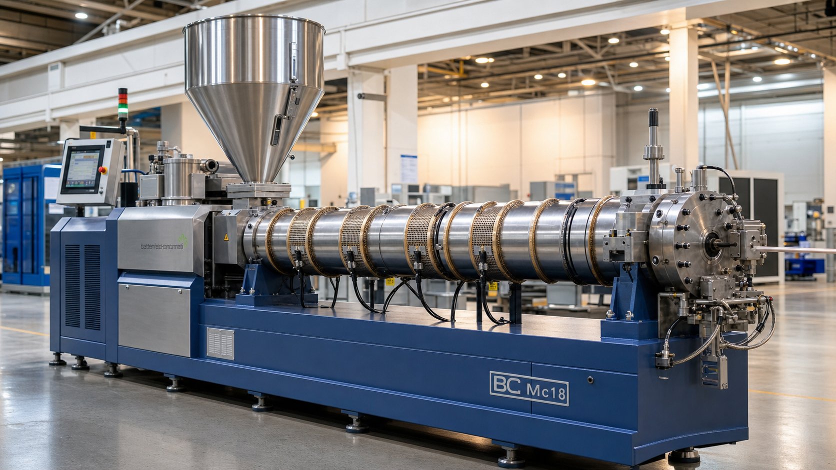
A single screw extruder is a continuous processing machine that uses one rotating Archimedean screw inside a heated barrel to convey, melt, mix, and pressurize raw material — typically polymer pellets, granules, or powder — and force the resulting homogeneous melt through a shaped die to produce a continuous profile.
This guide goes far beyond that definition. Ahead, you'll find a detailed breakdown of every critical component, a deep dive into the three functional zones that most resources gloss over, screw design theory that connects geometry to real-world performance, a head-to-head comparison with twin screw systems, application guidance spanning multiple industries, a practical troubleshooting matrix, and maintenance strategies that extend equipment life. Consider it the single most comprehensive resource you'll need on this technology.
What Is a Single Screw Extruder
The operating concept is surprisingly straightforward. Solid feedstock — usually thermoplastic pellets or powder — drops from a hopper into the barrel under gravity. A motor-driven screw rotates inside that barrel, gripping the material through friction and pushing it forward. As the material advances, it encounters progressively higher temperatures from barrel-mounted heaters and intense shear forces generated by the screw's geometry. These two heat sources — conducted thermal energy from the barrel wall and viscous dissipation from mechanical shear — work together to transform solid granules into a uniform, flowing melt.
Once fully melted and homogenized, the polymer is forced under pressure through a die at the barrel's exit. The die's shape determines the final product geometry: a round opening for pipe, a flat slot for sheet, an annular gap for blown film, or a complex cross-section for custom profiles. Downstream equipment then cools, sizes, and cuts the extrudate into its finished form.
What makes this technology so widespread? Simplicity, reliability, and cost-effectiveness. A single screw extrusion machine has fewer moving parts than its twin screw counterpart, requires less complex maintenance, and delivers consistent output over long production runs. These advantages explain why single-screw systems command roughly 62% of the global extrusion machinery market — a dominant share that reflects their deep entrenchment in high-volume manufacturing.
Why Single Screw Extrusion Matters in Modern Manufacturing
The reach of this technology extends well beyond plastics. In the food industry, screw extruders shape snack foods, breakfast cereals, pasta, and pet food with gentle, consistent processing. Pharmaceutical manufacturers rely on hot-melt extrusion to create solid dispersion drug delivery systems. Rubber processors use these machines to produce automotive seals, hoses, and gaskets. And across all of these sectors, the underlying principle stays the same: one rotating screw, one heated barrel, continuous output.
Despite growing interest in twin screw extruders for compounding and reactive processing, single screw machines remain the undisputed workhorse for steady-state, high-volume extrusion tasks. The global extrusion machinery market — valued at USD 9.45 billion in 2025 and projected to reach USD 14.12 billion by 2034 — continues to see strong demand for these systems across construction, packaging, automotive, and consumer goods sectors.
Here's the key insight that separates experienced engineers from everyone else: a screw extruder is only as good as the operator's understanding of what happens inside it. Screw design, zone mechanics, temperature profiles, and material behavior all interact in ways that directly determine product quality, throughput, and energy efficiency. Whether you're an engineer optimizing a production line, a student learning polymer processing fundamentals, or a procurement professional evaluating equipment specifications, mastering these fundamentals transforms decision-making from guesswork into precision.
And it all starts with the components that make the machine work — each one engineered for a specific purpose within the extrusion process.
Essential Components of a Single Screw Extruder Machine
Every single screw extruder machine is essentially a system of interdependent parts, each engineered to handle a specific stage of the transformation from raw pellets to finished product. Strip away the outer panels and safety guards, and you'll find remarkably elegant engineering — precision-machined steel components working together under extreme temperatures and pressures. Understanding what each part does, and why it's built the way it is, gives you the ability to diagnose problems faster, specify replacements correctly, and optimize performance where it matters most.
Let's walk through each critical component, starting with the one that takes the most punishment.
Barrel Construction and Heating Systems
The barrel is the cylindrical housing that surrounds the screw and contains the polymer melt under pressure. Think of it as both an oven and a pressure vessel — it must conduct heat efficiently, resist wear from abrasive materials, and maintain incredibly tight bore tolerances over years of continuous operation.
Barrel metallurgy determines lifespan. The most common options include:
- Nitrided steel barrels — The base-level choice. A case-hardening process creates a hard surface layer (typically 55-70 HRC) on the bore. Cost-effective for processing unfilled polyolefins and clean feedstock, but wears relatively quickly with abrasive materials.
- Bimetallic barrels — A centrifugally cast alloy liner (often iron-boron or nickel-cobalt based) bonded inside a standard steel shell. Hardness reaches 60-70 HRC with superior abrasion and corrosion resistance. This is the preferred choice for recycling applications and filled compounds.
- Tungsten carbide liners — Reserved for extreme applications like processing 40%+ glass-fiber-filled nylon. Expensive, but barrel life can extend 3-5x longer than standard bimetallic options.
Bore tolerance is critical here. When the clearance between screw flights and the barrel wall increases beyond approximately 0.1-0.15 mm per side, you start losing output, melt quality, and energy efficiency. That's a gap roughly the thickness of a sheet of paper — and it separates profitable production from expensive scrap.
Heating systems divide the barrel into 3-7 independent temperature zones, each with its own setpoint and controller. The most common heater screw configurations — meaning thermocouple-equipped barrel zones paired with appropriate heating elements — use one of these technologies:
- Mica band heaters — Cheapest option with limited watt density. Suitable for low-temperature applications.
- Ceramic band heaters — Better insulation, higher efficiency, and more uniform heat distribution. The standard for most modern extruders.
- Cast aluminum heaters — Excellent heat transfer and uniformity. Reduce energy consumption by 15-25% compared to mica bands.
- Induction heating — The newest technology, heating the barrel directly through electromagnetic induction for faster response times and up to 30% energy savings.
Equally important are the cooling systems. When shear heating pushes a zone above its setpoint, air-cooling fans or water-cooled jackets activate to bring temperatures back in line. Without adequate cooling, you lose temperature control entirely — and thermal degradation follows quickly. The interplay between heating and cooling across zones is what allows operators to create precise temperature profiles tailored to specific polymers.
Screw Materials, Coatings, and Drive Systems
If the barrel is the pressure vessel, the extruder screw is the heart. This single rotating component simultaneously conveys, melts, mixes, and meters the polymer. Get the metallurgy wrong, and you're replacing it far sooner than necessary.
A single extruder screw typically starts with one of these substrate materials:
- Nitrided 4140 steel — The industry workhorse for general-purpose applications. Offers good toughness and a hardened surface layer. Cost-effective for processing standard polyolefins without fillers.
- Tool steels (D2, H13) — Higher hardness and better wear resistance than 4140. Selected for moderately abrasive applications.
- Powder metallurgy alloys (CPM 9V, CPM 10V) — Premium materials for extreme wear environments. Provide exceptional edge retention on flight lands.
The substrate alone rarely provides enough protection. Hard-facing and coatings extend service life dramatically — especially on flight lands and in the compression zone where wear concentrates. Common options include Stellite overlays for combined wear and corrosion resistance, and tungsten carbide coatings for ultimate hardness when processing glass-filled or mineral-filled compounds. Research published in the Polymer Engineering & Science Journal shows that bimetallic and hard-faced screws can extend service life by up to 5x compared to standard nitrided steel when processing abrasive plastics.
The drive system translates electrical energy into the mechanical force that rotates the screw. Modern systems pair an AC motor with a variable-frequency drive (VFD) and a reduction gearbox. Here's why each element matters:
- AC motor with VFD — Provides precise speed control from about 10% to 100% of rated RPM, smooth acceleration during cold starts, and 15-30% energy savings compared to older DC systems.
- Gearbox — Reduces motor speed (typically 1,500 RPM) to screw speed (75-100 RPM) while multiplying torque by a factor of 15:1 to 20:1. Often the most expensive single component in the drive train.
- Thrust bearing assembly — Absorbs the enormous axial force generated as the screw pushes melt forward against die resistance. On large extruders, this load can exceed 50 tons.
The torque and speed ratings of your drive system directly determine throughput capacity. A 90mm extruder processing HDPE might require a 75-110 kW motor; scale up to a 150mm screw for high-throughput production and you're looking at 200-350 kW. Undersizing the drive means you'll never reach the screw's design output — oversizing wastes capital on capacity you can't use.
Hopper, Die, Screen Pack, and Breaker Plate
The hopper sits atop the barrel at the feed throat — the entry point where raw material begins its journey. Sounds simple, but hopper design directly affects output consistency. Two primary configurations exist:
- Flood-fed (gravity-fed) — Material falls into the feed throat under its own weight. The screw channel fills completely each revolution. This is the standard for most extrusion operations using uniform pellets with good flow characteristics.
- Starve-fed (metered) — A separate feeder controls exactly how much material enters the barrel per unit time. The screw channel is only partially filled. This configuration provides tighter control over residence time and is common in specialty applications where precise dosing matters.
One detail most operators overlook: the feed throat is almost always water-cooled. If heat migrates back from the barrel, pellets soften and stick together before the screw can grab them — creating a plug that stops production instantly. Keep that cooling water flowing.
At the opposite end of the machine sits the breaker plate — a thick metal disc with dozens of drilled holes positioned between the screw tip and the die. It serves a dual purpose. First, it supports the screen pack (layered wire mesh screens) that filters unmelted particles, degraded polymer chunks, and foreign contaminants from the melt stream. Second, it converts the rotational flow imparted by the screw into linear, axial flow. Without this conversion, the melt would enter the die with a spiraling motion, causing visible swirl marks in finished products.
Finally, the die itself — the precision-machined nozzle that shapes everything. The internal flow channels guide molten polymer from a round barrel exit into whatever geometry the application demands:
- Flat film dies — Wide slot openings with coat-hanger manifolds for uniform thickness distribution
- Annular blown film dies — Ring-shaped gaps with spiral mandrel designs that minimize weld lines
- Pipe dies — Annular exits paired with sizing sleeves and vacuum tanks for dimensional control
- Profile dies — Custom-designed cross-sections for window frames, decking, trim, and specialty shapes
- Strand dies — Multi-hole plates for pelletizing operations where strands are cooled and chopped
- Sheet dies — Wide-slot designs with adjustable lip gaps for thermoforming stock production
Each die shape determines the final product geometry — and each demands specific internal flow channel engineering to ensure the melt exits at uniform velocity across the entire cross-section. A variation of just 0.05 mm across a two-meter-wide sheet die lip creates visible thickness bands in the product. That's the level of precision these components require.
With every component working in concert — barrel containing and heating, screw conveying and melting, breaker plate filtering and straightening, die shaping — the real question becomes: what actually happens to the material as it travels through the barrel? The answer lies in three distinct functional zones, each governed by different physics and each demanding different screw geometry to perform its job.
How the Three Functional Zones Transform Raw Material Into Melt
Most explanations of single screw extrusion stop at "the screw melts the plastic." That's a bit like saying a car engine "burns fuel" — technically true, but useless for anyone trying to diagnose a misfire. The reality is far more interesting, and far more consequential for the quality of whatever comes out the other end.
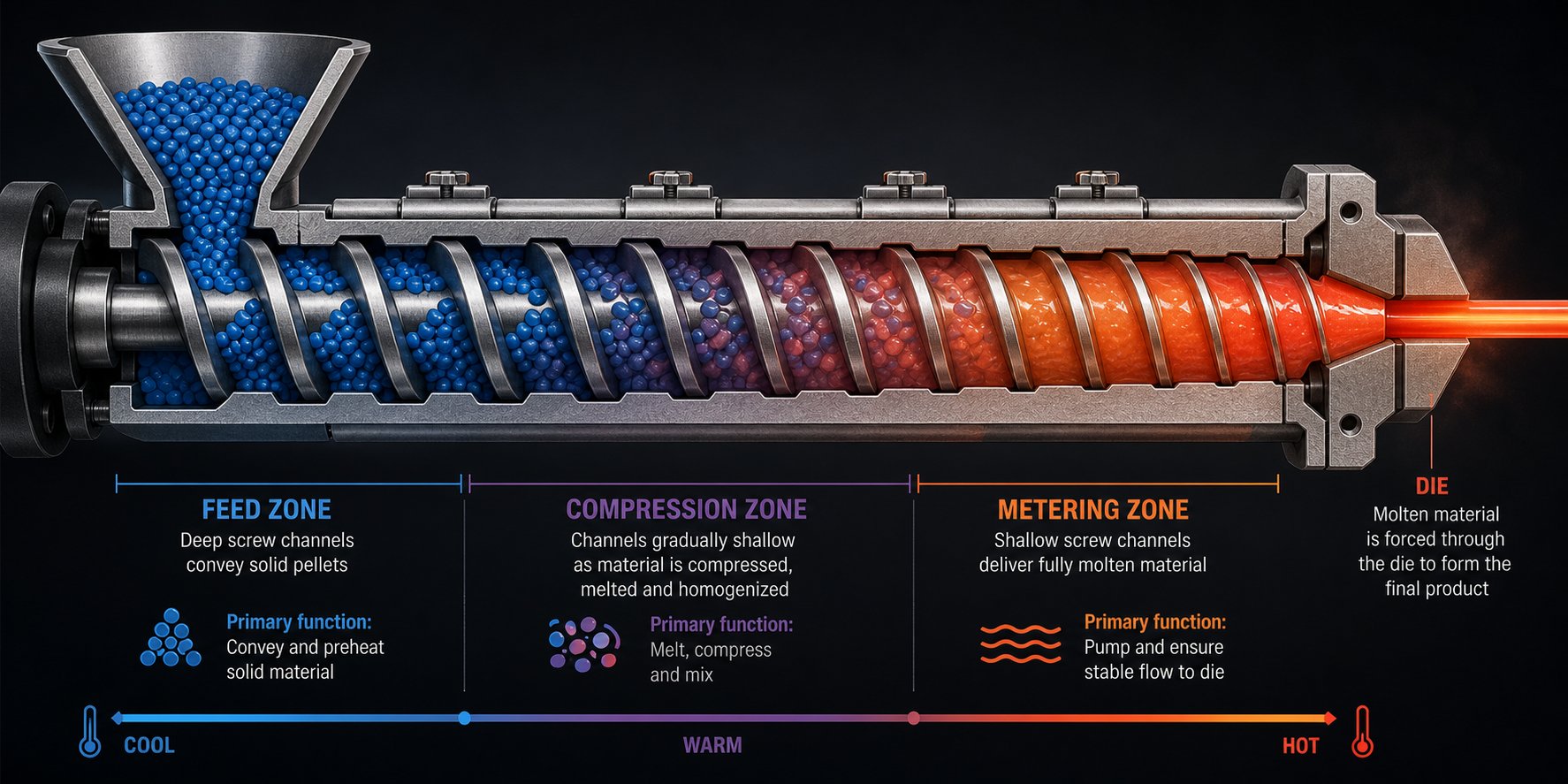
Inside every standard three-zone screw, raw pellets undergo a carefully orchestrated transformation governed by friction, compression, and viscous shear. Each zone has a distinct job, distinct geometry, and distinct physics. Get any one of them wrong and the entire process suffers — surging output, poor melt quality, inconsistent dimensions, or all three at once.
Let's break down exactly what happens in each zone and why it matters.
Feed Zone and Solids Conveying Mechanics
The feed zone is where everything begins — and where most people stop paying attention too soon. You'll notice this section of the screw has the deepest channels, and that's deliberate. Deep channels maximize the volume available to accept granular or powdered feedstock as it drops from the hopper under gravity.
Here's the part that surprises many engineers: the material doesn't move forward because the screw pushes it. It moves forward because of a friction imbalance. The pellets advance along the barrel only when friction between the material and the barrel wall exceeds friction between the material and the screw surface. If the screw grips the pellets too tightly, they simply rotate with the screw and go nowhere. If the barrel grips them sufficiently, the screw's helical geometry translates rotation into forward axial movement.
This friction-driven conveying mechanism is why feed throat cooling matters so much. A warm screw root increases screw-side friction, which reduces the friction differential and kills conveying efficiency. It's also why barrel surface finish in the feed zone is sometimes intentionally roughened while the screw root is kept polished — engineers are deliberately engineering that friction imbalance.
For polyolefins like HDPE and PP, grooved feed barrels have become a game-changing innovation. Longitudinal or helical grooves machined into the barrel's inner surface in the feed zone dramatically increase barrel-side friction. Research at the University of Stuttgart has demonstrated that grooved feed zones can roughly double the mass throughput compared to smooth barrels at low screw speeds — and critically, they decouple throughput from die backpressure. In a smooth barrel system, increasing die resistance reduces output. In a grooved system, the feed zone builds so much pressure on its own that downstream resistance has minimal effect on the conveying rate.
The same research revealed that granule shape and size significantly influence solid conveying behavior. Smaller, spherical particles maintained linear throughput increases up to 1,200 RPM in smooth barrels, while larger lenticular pellets hit their throughput ceiling around 300 RPM. For any extruder for polymer processing, this means feedstock consistency isn't just a quality preference — it's a throughput variable.
Compression Zone and the Melting Process
Imagine squeezing a handful of ice cubes between two warm surfaces while simultaneously pushing them forward. That's a rough analogy for what happens in the compression zone — also called the transition zone — where the real transformation occurs.
The defining geometric feature here is a gradually decreasing channel depth. As the screw root diameter increases, the available channel volume shrinks, compressing the solid bed tighter and tighter against the heated barrel wall. This compression does three critical things simultaneously:
- Forces air trapped between pellets back toward the feed zone and out through the hopper
- Increases pellet-to-barrel contact pressure, improving conductive heat transfer
- Generates enormous shear forces as the compacted material is dragged along the barrel surface
The melting mechanism itself follows a well-documented pattern that researchers have studied extensively since the 1960s. A thin melt film forms first at the barrel wall — the hottest surface the solid material contacts. As the screw rotates, each advancing flight scrapes this melt film off the barrel surface like a squeegee, collecting it into a growing melt pool on the pushing side of the screw channel. Meanwhile, the remaining solid bed — now smaller — is pressed against the barrel wall by the screw's geometry, forming a new melt film that will be scraped in the next revolution.
This drag-induced melting model, conceptually aligned with the foundational Tadmor melting theory, explains a critical reality: barrel heaters don't do most of the melting. For most resins, especially polyolefins, the majority of melting energy comes from viscous shear heating — the mechanical work generated as the screw flights deform and stretch the softened polymer. Barrel heaters define the thermal boundary and initiate that first melt film, but the screw's geometry is the real melting engine.
This is exactly why compression ratio — defined as the feed zone channel depth divided by the metering zone channel depth — matters so much. A screw with a 3.5:1 compression ratio aggressively reduces channel volume, generating high shear and pressure. That works beautifully for crystalline polymers like HDPE that need intense energy input to overcome their latent heat of fusion. But run heat-sensitive PVC through that same screw and you'll degrade the material before it exits the die. PVC typically requires compression ratios closer to 2:1, while crystalline polyolefins perform best in the 3:1 to 4:1 range. Matching compression ratio to material isn't optional — it's the single most important screw specification for melting performance.
Metering Zone and Pressure Generation
By the time material reaches the metering zone, it should be fully molten and homogenized. "Should be" is doing a lot of work in that sentence — because if the feed and compression zones haven't done their jobs properly, the metering zone inherits a mess it was never designed to clean up.
The metering zone has the shallowest channel depth on the screw. This narrow gap serves a precise purpose: it controls the flow rate and generates the stable, uniform pressure needed to push the melt through the screen pack, breaker plate, and die. Think of it as a precision metering pump, delivering a consistent volumetric flow regardless of minor fluctuations upstream.
Simulation research from the University of Applied Sciences Upper Austria has modeled the melt conveying behavior in this zone as a superposition of two flow components: drag flow (forward movement driven by the rotating screw surface pulling the melt) and pressure flow (backward leakage caused by the high pressure at the die end pushing melt back along the channel). The net output is the difference between these two opposing flows. When they're balanced correctly, you get stable extrusion. When they're not, pressure oscillations ripple through the entire process.
Consistent metering zone output is the single most important factor for dimensional stability in finished products. A pipe with fluctuating wall thickness, a film with uneven gauge, a profile with wavy edges — all of these defects trace directly back to instability in this zone. Even small changes in channel depth from screw wear can shift the drag-to-pressure flow balance enough to create measurable product variation.
Product quality in screw extrusion is largely determined by what happens in the metering zone — it is the final gatekeeper that either delivers a stable, uniform melt to the die or passes along every upstream inconsistency as a visible defect in the finished product.
The practical implication for operators is straightforward: if you're chasing dimensional problems, look at the metering zone first. Monitor die pressure for cyclical fluctuations, check screw flight diameters for wear, and verify that the temperature profile in this zone keeps the melt viscosity within a tight, stable range.
Together, these three zones form a sequential system where each stage depends on the one before it. Consistent solids conveying feeds uniform compression, uniform compression produces homogeneous melting, and homogeneous melting enables stable metering. Break any link in that chain and the consequences cascade all the way to the product. The question that naturally follows: what specific screw geometry parameters control how well each zone performs its job?
Screw Design Parameters That Control Extrusion Performance
Every zone on a single screw extruder does its job — or fails at it — based on measurable geometric dimensions machined into the steel. Change a channel depth by two millimeters, alter a compression taper, or lengthen the screw by a few diameters, and you'll see the difference in output rate, melt temperature, and product quality within minutes. For engineers specifying a new extrusion screw, students learning the fundamentals, or procurement teams evaluating quotes for a single screw plastic extruder, understanding these parameters is the difference between selecting the right tool and paying for expensive trial and error.
L/D Ratio, Compression Ratio, and Their Impact on Output
The L/D ratio — screw length divided by screw diameter — is the first number most people look at when comparing machines. It tells you how much working length the polymer has to travel through, and by extension, how much time and energy the screw can invest in melting and mixing. Common values for a plastic single screw extruder fall in the 20:1 to 30:1 range, though high-performance applications — particularly those requiring intensive mixing or processing of engineering polymers — may extend to 36:1 or beyond.
What happens when you increase the L/D ratio? You gain more residence time inside the barrel, which translates to better melting uniformity, more opportunity for mixing, and the ability to run higher screw speeds without sacrificing melt quality. Sounds like a free upgrade — but it's not. Longer screws demand higher torque from the drive system, cost more to manufacture, and introduce structural risks. As research into screw parameter effects has noted, excessive L/D ratios heighten susceptibility to shaft deflection, which can cause the screw to contact the barrel wall — scoring both components and shortening their service life considerably.
Material properties guide the selection. Thermally sensitive polymers like PVC benefit from shorter L/D ratios because extended residence time increases the risk of degradation. Conversely, materials requiring higher processing temperatures and pressures, or unprocessed powders that need thorough homogenization, favor longer screws. Pre-pelletized feedstock that has already been compounded can often be processed effectively with shorter designs.
Compression ratio — feed zone channel depth divided by metering zone channel depth — is the other foundational parameter. It controls how aggressively the screw compacts and melts the solid bed. The values vary significantly by polymer family, and getting this wrong is one of the most common sources of extrusion problems.
Here's a practical reference for common materials, based on published compression ratio data:
| Polymer | Typical Compression Ratio | Notes |
|---|---|---|
| Polyethylene (PE) | 3:1 to 4:1 | Crystalline; requires high energy input for melting |
| Polypropylene (PP) | 2.5:1 to 4:1 | Wide range depending on melt flow index |
| Rigid PVC (granules) | 2:1 to 3:1 | Heat-sensitive; low compression prevents degradation |
| Rigid PVC (powder) | 3:1 to 4:1 | Higher ratio needed to densify loose powder |
| ABS | 1.6:1 to 2.5:1 | Amorphous; lower compression suits its gradual softening |
| Polycarbonate (PC) | 2.5:1 to 3:1 | Moderate compression for this engineering resin |
| Polyamide 66 (PA66) | 3.7:1 | Highly crystalline; sharp melt point demands aggressive compression |
| Polystyrene (PS) | 2:1 to 4:1 | Amorphous; wide processing window allows flexibility |
Notice the pattern: crystalline polymers with sharp melting points and high heats of fusion — PE, PA66 — need aggressive compression ratios to deliver enough energy for complete melting. Amorphous resins like ABS and PC, which soften gradually over a broad temperature range, work best with gentler compression. Choosing a compression ratio that matches your specific resin is arguably the most consequential single decision in screw design for any screw plastic extruder application.
Flight Depth, Pitch, Helix Angle, and Channel Geometry
If L/D ratio and compression ratio set the broad strokes of screw performance, flight depth, pitch, and helix angle fill in the fine details. These parameters interact with each other in ways that aren't always intuitive, and adjusting one often creates ripple effects in the others.
Flight depth — the distance from the top of the flight to the screw root — controls two critical but competing functions. In the feed zone, deep channels maximize volumetric intake, allowing the screw to grab as much raw material as possible each revolution. A deep feed section groove enhances the screw's conveying ability, but excessive depth weakens the screw structurally and can create inconsistent mixing within the channel, disrupting heat transfer and hindering plasticization. In the metering zone, shallow channels increase shear rate — which improves mixing and heat generation — but reduce the volumetric throughput available. Every screw design is a compromise between these tensions.
Pitch — the axial distance between consecutive flights — determines how far material advances per screw revolution. The industry standard is a square-pitch design, where pitch equals the screw diameter. This geometry produces a helix angle of approximately 17.66 degrees (often written as 17°41'), which provides a practical balance between conveying rate and residence time for most thermoplastics.
Modifying pitch from the standard square design changes the conveying dynamics considerably. Increasing pitch accelerates material movement but reduces residence time and the shear energy input. Decreasing pitch slows conveyance, compresses the material more within each turn, and increases the available time for heat transfer. Some advanced extrusion screw designs use variable pitch along the screw length — wider pitch in the feed zone for rapid intake, transitioning to narrower pitch in the metering zone for better pressure generation.
Helix angle — the angle between the flight and a plane perpendicular to the screw axis — is geometrically linked to pitch and diameter. Its primary influence is on drag flow: the component of melt movement driven by the rotating screw surface pulling the polymer forward. At a helix angle of approximately 30 degrees, theoretical extrusion flow rate in the metering section reaches its maximum. However, practical considerations — including ease of manufacturing and the need to balance feed zone performance — keep most production screws closer to the 17-18 degree range. For the feed section specifically, optimal angles vary by feedstock shape: around 30 degrees for powder, approximately 15 degrees for square-cut granules, and roughly 17 degrees for spherical or cylindrical pellets.
Barrier Screws and Advanced Mixing Elements
Standard three-zone screws rely entirely on the compression zone's decreasing channel depth to accomplish melting. The problem? As the solid bed shrinks and the melt pool grows, the two phases coexist in the same channel, and the solid bed can break apart unpredictably — sending unmelted fragments downstream into the metering zone. The result is inconsistent melt quality, gels in the final product, and frustrating output variability.
Barrier screw designs solve this by introducing a secondary flight — called the barrier flight — that physically separates the solid bed from the melt pool. The barrier flight is intentionally machined with a slightly smaller outer diameter than the main flight, creating a precisely controlled gap. This gap allows molten polymer to pass over the barrier into a dedicated melt channel while keeping unmelted solids trapped in the solids channel until they fully melt. The result is dramatically improved melting efficiency, higher output uniformity, and fewer unmelts in the finished product.
Barrier screw technology originated in rubber processing when Geyer at Uniroyal developed the concept in 1961. Within about a decade, the melt-solid separation principle migrated to thermoplastic processing and became the state of the art. Today, barrier designs are standard on virtually every high-output single screw plastic extruder processing polyolefins for pipe, film, and sheet applications.
Even with barrier screws handling the melting stage efficiently, most applications benefit from a dedicated mixing section placed between the barrier zone and the metering zone — or at the screw tip. These elements improve thermal homogeneity, distribute colorants and additives, and eliminate any remaining temperature gradients in the melt. The key distinction is between dispersive mixers (which apply high shear to break down agglomerates) and distributive mixers (which divide and recombine the melt stream to create uniformity without adding significant shear energy).
As extrusion consultant Jim Frankland of Frankland Plastics Consulting has pointed out, many barrier screws in operation are equipped with high-shear dispersive mixers when they don't need them. Since a properly designed barrier section should complete melting on its own, adding a dispersive mixer after it often just increases melt temperature needlessly, reduces output due to added pressure drop, and raises energy costs. For most barrier screw applications, a distributive mixer is the better choice.
Here are the most common mixing element types you'll encounter on a screw plastic extruder:
- Maddock (Union Carbide) mixer — A dispersive design with alternating inlet and outlet channels separated by barrier lands. Forces all melt through a narrow shear gap, ensuring every polymer molecule experiences high shear stress. Best suited for conventional (non-barrier) screws where supplemental melting is needed.
- Spiral Maddock mixer — A modern evolution that combines features of the original Maddock and Egan designs, with helical channels that reduce pressure drop while maintaining effective shear. Currently the most widely used dispersive mixer in the industry.
- Pineapple mixer — A distributive design that divides the melt into multiple streams that converge at varying angles, creating chaotic mixing patterns. Particularly effective for color dispersion and additive distribution.
- Pin mixer — Uses rows of pins protruding from the screw root to divide and recombine the melt exponentially. Creates an extremely large number of material layers and handles viscosity mismatches well, though it can generate significant pressure drop.
- Saxton mixer — A distributive element with multiple interrupted flights that divide the melt into separate channels, relying on similar principles to the metering section itself. Can be designed for very low pressure drop, making it ideal for thermal homogenization.
- Blister ring — A simple cylindrical restriction that forces all melt through a narrow annular gap between the ring and the barrel wall. Provides a pressure seal and moderate dispersive mixing. Often used as a dam between functional screw sections.
Selecting the right mixing element depends on what problem you're solving. Adding color to a clear resin? A pineapple or pin mixer distributes pigment without overheating the melt. Processing a conventional screw that delivers incomplete melting? A Maddock mixer provides the dispersive shear needed to finish the job. Running a well-designed barrier screw that just needs thermal homogenization? A Saxton mixer handles it with minimal pressure loss.
These screw geometry decisions — L/D ratio, compression ratio, flight depth, pitch, barrier design, mixer selection — don't exist in isolation. They interact as a system, and the best extrusion screw for any application is one where every parameter is specified with both the material properties and the downstream die requirements in mind. That systems-level thinking naturally raises a broader question: when does a single screw design make more sense than a twin screw system, and how do their fundamental capabilities actually compare?
Single Screw vs Twin Screw Extruder Comparison
Screw geometry, zone mechanics, and mixer selection all shape what a single screw extruder can accomplish. But at some point, every engineer or procurement professional faces a different kind of question entirely: should we be looking at a twin screw system instead? The answer depends not on which machine is more advanced, but on which one matches the material, the mixing duty, and the production goal. Treating a twin screw as universally "better" is one of the most expensive mistakes in extrusion — and so is forcing a single screw into a role it wasn't designed for.
What's missing from most comparisons is a single, structured resource that covers every decision factor in one place. Let's fix that.
Head-to-Head Comparison of Single and Twin Screw Extruders
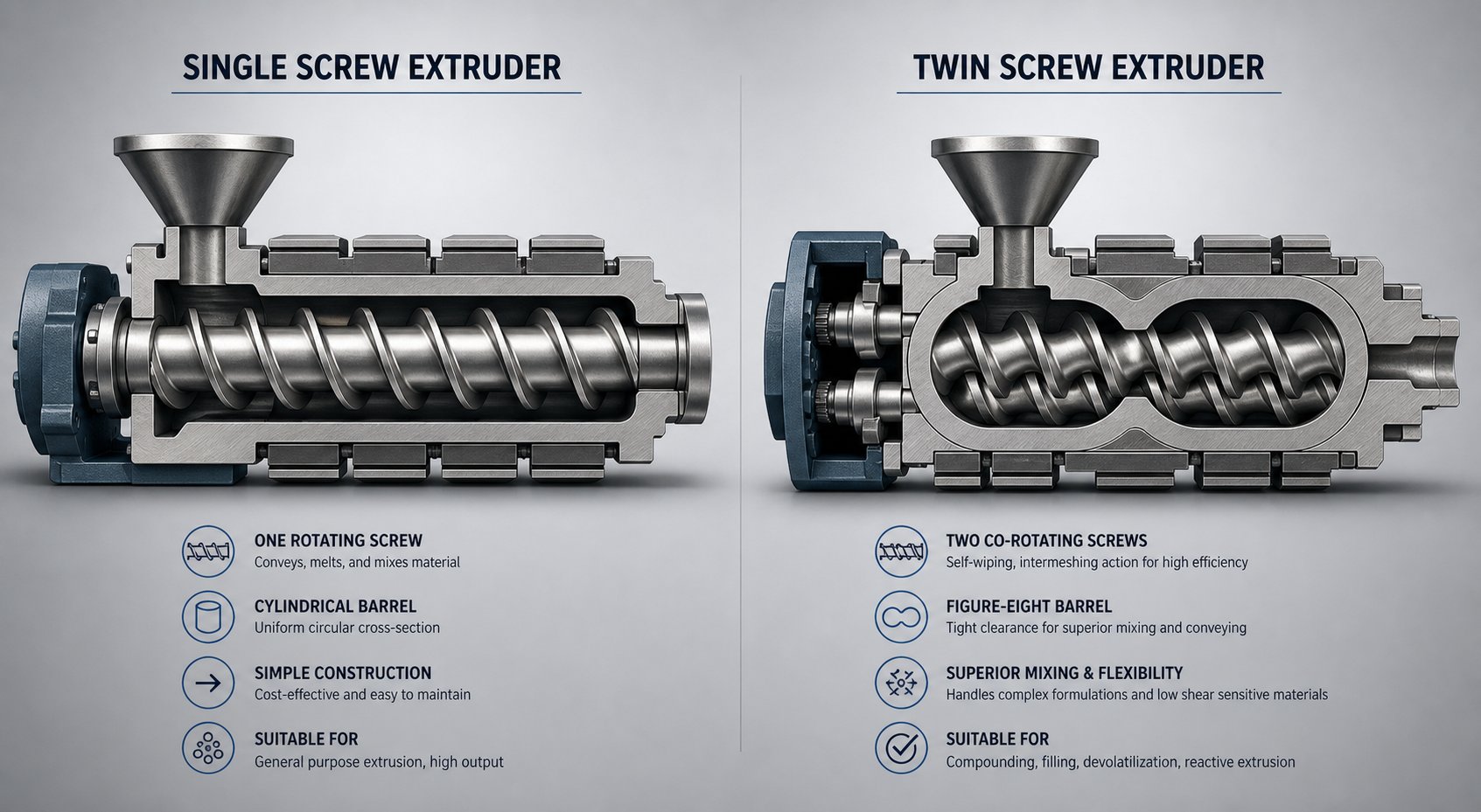
The fundamental design difference drives everything else. A single screw extruder relies on friction and drag flow to move material — the polymer must frictionally adhere to the barrel wall to be conveyed forward. A twin screw extruder uses two intermeshing screws that physically push material forward through positive displacement, regardless of the feedstock's friction characteristics. That distinction ripples through every performance metric, from mixing intensity to capital cost.
Here's how the two systems compare across the factors that actually drive purchasing and process decisions:
| Decision Factor | Single Screw Extruder | Twin Screw Extruder |
|---|---|---|
| Mixing Capability | Low to moderate; limited by single-channel flow where polymer stays in relatively the same radial position, making complete channel mixing difficult | Moderate to high; intermeshing screws transfer the entire channel of polymer from one screw to the other multiple times, enabling full-channel dispersive and distributive mixing |
| Shear Rates | Shear is highest at the barrel wall and decreases to near zero at the screw root; high-shear mixing sections cause significant pressure drop and output loss | High shear can be applied in small increments through multiple changes in channel depth and mixing lobes without subjecting the bulk melt mass to excessive shear energy |
| Throughput Consistency | Excellent for steady-state processing of pre-compounded pellets; consistent die pressure under stable conditions | Highly consistent even with variable feedstocks; positive displacement maintains stable feed rates regardless of material form |
| Residence Time Distribution | Broader distribution; some polymer may reside longer in slow-moving regions near the screw root | Tighter, more uniform distribution; starved operation and screw-to-screw transfers promote even exposure times |
| Self-Wiping Behavior | No self-wiping capability; material can stagnate in dead spots, increasing degradation risk for heat-sensitive polymers | Co-rotating intermeshing designs are fully self-wiping, continuously cleaning the screw surfaces and minimizing material hang-up |
| Feedstock Flexibility | Best with uniform pellets and granules; struggles with fine powders, fluffy regrind, and inconsistent bulk density materials | Handles powders, dry blends, variable recycled feedstock, and high-filler-loading formulations with ease |
| Degassing and Venting | Limited capability; vented barrel designs exist but are less effective at removing volatiles | Superior performance; starved operation and multiple vent ports efficiently remove moisture and volatile compounds |
| Capital Cost | Lower purchase price; simpler gearbox, single screw manufacturing, and less complex barrel design reduce upfront investment | Significantly higher; precision-machined intermeshing screws, heavy-duty gearboxes, and modular barrel sections increase the twin screw extruder price substantially |
| Maintenance Complexity | Simpler to maintain; fewer wear parts, less cleaning required, faster operator training | More complex; modular screw elements require careful reassembly, more wear surfaces to inspect, and greater process knowledge from operators |
| Pressure Generation | Excellent pressure buildup for die feeding; the continuous screw channel efficiently generates the high pressures required by restrictive dies | Lower inherent pressure generation; some designs require a discharge zone or gear pump to build sufficient die pressure |
| Energy Efficiency | Generally more energy-efficient for straightforward melting and conveying tasks due to simpler mechanical design and lower drive requirements | Higher energy input per kilogram for most operations, though efficiency gains from reduced waste and better mixing can offset this in compounding applications |
| Best-Fit Applications | Pipe, tubing, blown and cast film, sheet, profile, wire coating, and pelletizing of pre-compounded materials | Compounding, masterbatch production, reactive extrusion, devolatilization, PVC dry-blend processing, and recycling of mixed or contaminated streams |
One nuance that often gets overlooked in these comparisons: the inherent mixing limitation of a single screw isn't just about having one screw instead of two. As extrusion expert Jim Frankland has explained, twin screws can transfer the entire channel of polymer from one screw to the other multiple times — permitting full-channel mixing with precisely controlled shear. A single screw's channel contents tend to stay in the same radial position due to shear thinning, making truly complete mixing difficult regardless of how many mixing elements are added. Various attempts to replicate twin-screw-like mixing in single-screw systems have been made, but except at very limited outputs, none have been adequate.
That said, when mixing demands are modest and the goal is reliable melting and shaping, the single screw's simplicity becomes a genuine competitive advantage — not a compromise.
When to Choose Single Screw Over Twin Screw
The decision framework is more practical than most resources make it seem. Start with two questions: What form is your raw material in? And does the extruder need to do the mixing, or has that already been done upstream?
If the feedstock is a stable, pre-compounded pellet — and the extrusion line's primary job is to melt that material and deliver it at consistent pressure to a die — a single screw extruder is almost always the right architecture. This describes the vast majority of pipe, film, sheet, profile, and wire coating lines worldwide. The material arrives uniform. The extruder melts it, meters it, and shapes it. There's no need for the intensive mixing, powder handling, or devolatilization capabilities that justify a twin screw's added cost and complexity.
Twin screw systems earn their place when the extruder itself must combine base resin, fillers, stabilizers, pigments, modifiers, or recycled material into a homogeneous compound. Reactive extrusion, color masterbatch production, glass-fiber reinforcement, PVC dry-blend processing, and recycling of contaminated post-consumer waste all demand the kind of intensive internal mixing and material control that twin screws provide. For these applications, the higher capital cost and operational complexity aren't optional luxuries — they're the processing tools that match the duty.
Here's a quick checklist to clarify the decision. If most of these statements describe your operation, single screw is likely the practical route:
- The material is pre-compounded pellets or granules with consistent bulk density
- The formulation is already mixed before it reaches the extruder
- The product is pipe, tube, hose, profile, film, sheet, or coated wire
- Stable die pressure and continuous output matter more than internal mixing
- Lower maintenance burden and simpler operator training are priorities
- The extruder does not need to perform compounding, devolatilization, or reactive processing
If instead the answers point toward powder feeding, variable recycled inputs, high filler loading, or additive dispersion — whether you're evaluating a new twin screw extruder for sale or sourcing a used twin screw extruder for an expanding recycling line — the twin screw architecture deserves serious consideration. The right choice isn't the more complex machine. It's the one whose screw architecture matches the material and the product.
If the primary goal is melting and shaping a pre-compounded material, a single screw extruder is typically the most economical and reliable choice — the added capability of a twin screw system only creates value when the process genuinely requires it.
When evaluating used twin screw extruder for sale listings or comparing a twin screw extruder price against a single-screw alternative, keep this principle front and center. The cheapest machine is always the one that's correctly matched to the job — not the one with the lowest sticker price or the most impressive spec sheet.
This comparison clarifies the machine-level decision, but the real value of a single screw extruder only becomes visible when you see the breadth of industries and materials it serves — and how screw configuration adapts to each one.
Industry Applications and Material-Specific Extrusion Guidance
A well-designed screw matched to the wrong application still produces bad parts. And a perfectly specified machine sitting in the wrong industry segment wastes capital every hour it runs. The versatility of a single screw extruder is genuinely impressive — but that versatility only creates value when the die geometry, screw configuration, and downstream equipment align with the specific demands of the product being manufactured. Let's walk through the major sectors where these machines earn their keep, then drill into the material-level details that separate a good setup from a great one.
Plastics Extrusion Applications
Plastics processing remains the dominant application, and it's not even close. But lumping all "plastics extrusion" into one category hides the enormous variety of products, tooling, and process conditions involved. Each product category below demands a different die, different downstream cooling, and often a fundamentally different screw design:
- Pipe and tubing — HDPE water mains, PVC drainage lines, PP-R hot-water plumbing, medical tubing, and industrial hose. Annular dies feed into vacuum sizing tanks that lock in outer diameter and wall thickness. Screw designs for pipe typically feature barrier flights and high compression ratios to deliver the dense, void-free melt that pressure-rated pipe demands.
- Blown film — Packaging bags, agricultural mulch films, stretch wrap, and multi-layer barrier films. An annular die blows the melt into a bubble that's collapsed, slit, and wound. Uniform melt temperature is critical — even a 2-3 degree Celsius variation across the die creates visible thickness bands in the finished film.
- Cast film and sheet — Thermoforming stock, protective films, and rigid packaging. A flat die deposits melt onto polished chill rolls. Sheet lines demand extremely stable output pressure to prevent gauge variation across widths that can exceed two meters.
- Wire and cable coating — Insulation and jacketing layers applied over conductors at line speeds that can exceed 1,000 meters per minute. The extruder must deliver a consistent, bubble-free melt at precisely controlled pressure to a crosshead die mounted perpendicular to the wire path.
- Profile extrusion — Window frames, deck boards, trim, weatherstripping, and hundreds of custom cross-sections. Complex die geometries with calibration tables downstream require the polymer extruder to maintain rock-steady output and melt homogeneity.
- Pelletizing and granulation — Converting compounded material, recycled flake, or virgin resin into uniform pellets for downstream processing. A screw extruder granulator setup feeds a strand die whose output is water-cooled and chopped, or uses an underwater pelletizer for higher throughput. This application bridges compounding and forming — the extruder melts and homogenizes, while the pelletizer creates the feedstock other machines will use.
Notice the pattern: the extruder itself may look similar across these applications, but the screw geometry, die tooling, and downstream equipment create entirely different production lines. Buying the right barrel and screw combination without specifying the end product is like ordering an engine without knowing whether it goes in a sedan or a dump truck.
Beyond Plastics — Food, Pharmaceutical, and Rubber Extrusion
Plastics may dominate installed capacity, but some of the most technically interesting single screw applications live in entirely different industries. The underlying physics — convey, compress, transform, shape — translates remarkably well across material types when the equipment is properly adapted.
Food extrusion represents a massive global market. Imagine breakfast cereal being formed: grain-based dough enters the barrel, where controlled heat and shear cook the starch, develop texture, and build the puffed or shaped structure consumers expect. Single screw machines handle snack foods, breakfast cereals, pasta, and pet food with the gentle, consistent processing these products require. Unlike plastics extrusion, food applications demand stainless steel contact surfaces, food-grade lubricants, and hygienic designs that prevent contamination and allow thorough cleaning between product runs. The screw geometries tend toward lower compression ratios and wider flight clearances to avoid damaging delicate ingredients or generating excessive shear that could alter flavor and nutritional content.
Pharmaceutical hot-melt extrusion has emerged as a critical manufacturing platform for solid dispersion drug delivery systems. The challenge in pharmaceutical formulation is often that an active pharmaceutical ingredient (API) has poor water solubility, limiting how effectively the body can absorb it. By intimately dispersing the API within a polymeric carrier matrix through extrusion, formulators create amorphous solid dispersions that dramatically improve bioavailability. Single screw systems suit this application when the formulation is well-characterized and doesn't require the intensive mixing of a twin screw compounder — particularly for continuous manufacturing of established products where process simplicity and reliability reduce regulatory risk.
Rubber extrusion presents its own unique demands. Automotive door seals, radiator hoses, window gaskets, and tire tread components all pass through extruders — but unlike thermoplastics, rubber compounds undergo crosslinking reactions that are irreversible. The extruder must deliver the compound at a temperature high enough for flow but low enough to prevent premature vulcanization (known as "scorch") inside the barrel. As industry sources note, rubber processing requires more precise temperature regulation capabilities than typical plastics work, because the margin between processable and scorched can be as narrow as 10-15 degrees Celsius. Screws for rubber tend to be shorter (L/D ratios of 8:1 to 16:1) with lower compression ratios to minimize internal heat generation.
Material-Specific Considerations for Common Polymers
Here's where theory meets the factory floor. Every polymer interacts with screw geometry differently, and a screw optimized for one resin can be a poor — or even destructive — choice for another. You'll save yourself considerable time, material waste, and frustration by understanding how the most common polymers behave inside the barrel.
Polyethylene (PE) — Both HDPE and LDPE are crystalline polymers with well-defined melting points and relatively high heats of fusion. They benefit from high-compression barrier screw designs (compression ratios of 3:1 to 4:1) that deliver the aggressive energy input needed to fully melt the crystalline structure. Deep feed zones accommodate the relatively low bulk density of PE pellets, and grooved feed barrels significantly boost throughput for HDPE in particular. PE is forgiving in terms of thermal degradation — it tolerates a wide processing window — but it's sensitive to shear-induced melt fracture at high output rates.
Polypropylene (PP) — Similar to PE in its crystalline nature but with a narrower processing window and greater sensitivity to oxidative degradation at elevated temperatures. Compression ratios typically range from 2.5:1 to 4:1 depending on melt flow index. Higher MFI grades (thinner, easier flowing) require less aggressive compression, while low MFI grades demand more shear energy for complete melting. Antioxidant stabilization is critical, especially for a polyester extruder setup processing PP at the higher end of its temperature range.
Polyvinyl chloride (PVC) — The most demanding of the commodity polymers in terms of screw design constraints. PVC is highly heat-sensitive and begins to degrade (releasing hydrochloric acid) at temperatures only slightly above its processing window. This mandates low-shear, low-compression screws — typically 2:1 to 2.5:1 compression ratio for pre-compounded granules. Channel depths should be relatively shallow in the metering zone to avoid excessive residence time, and barrel temperatures must be controlled within a tight band. Corrosive wear from HCl byproducts also requires bimetallic barrels with corrosion-resistant liners. Running PVC through a screw designed for HDPE is a recipe for rapid degradation and barrel damage.
Polyethylene terephthalate (PET) — Hygroscopic and extremely sensitive to moisture during processing. Even 50 ppm of residual moisture causes hydrolytic chain scission that destroys mechanical properties. Pre-drying to below 30 ppm moisture content is non-negotiable. PET has a relatively sharp crystalline melting point around 260 degrees Celsius and requires moderate compression ratios (2.5:1 to 3:1). Melt viscosity drops rapidly with temperature, so precise zone control prevents the polymer from becoming too fluid and losing pressure stability in the metering section. Many PET extrusion lines — particularly for sheet and thermoforming — use barrier screws with distributive mixing sections to ensure thermal uniformity without excessive shear that would reduce intrinsic viscosity.
Nylon (PA6, PA66) — Highly crystalline with sharp melting points and very low melt viscosity once molten. Nylon transitions from solid to liquid almost abruptly, which demands aggressive compression ratios (3.5:1 to 3.7:1 for PA66) and careful transition zone design to handle the rapid phase change. Like PET, nylon is moisture-sensitive and requires thorough pre-drying. Its low melt viscosity creates challenges for pressure generation in the metering zone — shallow metering channels help maintain adequate die pressure, but excessive shear should be avoided to prevent thermal degradation and discoloration.
| Polymer | Key Screw Requirement | Critical Sensitivity | Recommended Compression Ratio |
|---|---|---|---|
| HDPE | High-compression barrier screw with deep feed zone | Melt fracture at high shear rates | 3:1 to 4:1 |
| PP | Moderate-to-high compression; adjustable to MFI grade | Oxidative degradation at high temperatures | 2.5:1 to 4:1 |
| PVC | Low-shear, low-compression with corrosion-resistant barrel | Thermal degradation releasing HCl | 2:1 to 2.5:1 |
| PET | Moderate compression; barrier design with distributive mixer | Moisture-induced hydrolysis | 2.5:1 to 3:1 |
| Nylon (PA66) | Aggressive compression; shallow metering zone | Sharp melt transition; moisture sensitivity | 3.5:1 to 3.7:1 |
The takeaway is clear: there is no universal screw. Every polymer family brings its own combination of crystallinity, thermal sensitivity, melt viscosity behavior, and moisture requirements that dictate specific screw geometry, barrel metallurgy, and temperature management. A facility processing multiple resins either maintains a library of application-specific screws or accepts compromised performance on some materials — a trade-off that directly affects product quality, energy consumption, and ultimately profitability.
Even with the perfect screw-material match, though, problems still arise during production. Temperatures drift, feedstock varies, wear accumulates. Knowing how to diagnose and correct the most common extrusion failures — surging, melt fracture, gels, and feed disruptions — is what separates efficient operations from ones drowning in scrap and downtime.
Troubleshooting Common Single Screw Extrusion Problems
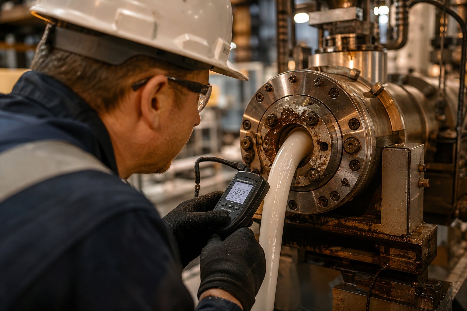
Production lines don't stop for theory. When output starts oscillating, surface defects appear on the product, or the hopper refuses to feed, operators and process engineers need answers they can act on immediately. Yet most technical resources dedicate entire chapters to screw geometry while offering nothing on what to do when things go wrong at two in the morning on a Thursday.
Whether you're running a brand-new industrial extruder machine or keeping a used extruder productive years after its original commissioning, the failure modes are remarkably consistent. The same handful of problems account for the vast majority of unplanned downtime. Understanding their root causes — and knowing where to look first — transforms reactive panic into systematic diagnosis.
Diagnosing Output Instability and Surging
Surging is the most common and most frustrating problem in single screw extrusion. You'll recognize it as cyclical fluctuations in output rate, die pressure, and motor current — the extruder seems to breathe, pushing out material in waves instead of a steady stream. The period can range from a few seconds to over 25 minutes depending on the root cause, and the consequences cascade into wall thickness variation, dimensional drift, and scrap rates that erode profitability fast.
What causes it? Dow fellow Mark Spalding, who has spent nearly four decades troubleshooting single-screw processes, identifies improper solids conveying as the most common root cause for smooth-bore extruders. The mechanism traces directly back to the friction balance discussed in the feed zone section of this article: material advances only when barrel-wall friction exceeds screw-surface friction. When temperatures in the solids conveying section drift outside their optimal range, that friction balance collapses.
Here's a logical diagnostic sequence when surging appears:
- Check the feed casing temperature. It should feel warm to the touch — never hot. If cooling water channels have become occluded with mineral deposits or rust, heat migrates backward from the barrel, softening pellets prematurely and disrupting conveying. Spalding documented a case where flushing the feed casing with an acidic solution and installing a dedicated cooling pump permanently eliminated surging that had plagued a PS extrusion line.
- Evaluate screw cooling (if equipped). A screw that runs too hot in the feed section increases retarding friction and reduces the forwarding force differential. On one 8-inch two-stage extruder, surging disappeared after the cooling bore was extended to cover the full length of the solids conveying section — the original bore fell three diameters short.
- Verify barrel zone 1 temperature. For many amorphous resins like PS, ABS, SAN, and PC, optimal barrel wall temperature in the feed zone corresponds to the peak of the resin's shear-stress-versus-temperature curve. Setting this zone too high or too low shifts the stress at the barrel-polymer interface and degrades conveying stability.
- Inspect screw and barrel for wear. Increased clearance between the screw flight OD and the barrel bore allows melt to leak backward over the flights, creating pressure oscillations that manifest as surging. If the clearance exceeds manufacturer specifications, no temperature adjustment will fully compensate.
- Review screw design suitability. A screw with the wrong compression ratio or channel geometry for the material being processed can produce inherent melting instabilities. This form of surging is rarer but impossible to fix without changing the screw.
One practical tip from Spalding's field experience: if a gear pump is installed between the extruder and the die, it can mask surging by maintaining constant downstream pressure — but the screw speed will oscillate wildly as the controller compensates. Monitor screw RPM and motor current trends, not just downstream output, to catch surging early.
Solving Melt Quality Problems
Output can be perfectly stable and you'll still produce scrap if the melt itself isn't right. Melt quality problems show up in the finished product as surface defects, internal inconsistencies, or degradation marks — and each symptom points to a different root cause.
Melt fracture creates a rough, distorted surface — sometimes described as sharkskin, spiral patterns, or wavy ridges — on the extrudate as it exits the die. The cause is straightforward: the melt's velocity at the die wall exceeds a critical threshold, and the polymer's elastic memory causes it to fracture and reform as it exits the constrained die geometry. Industry troubleshooting guidance recommends reducing output rate, increasing die temperature to lower melt viscosity at the wall, or widening the die gap to reduce wall shear stress. Switching to a resin grade with a higher melt flow index can also push the onset of melt fracture to higher output rates.
Die drool — that annoying buildup of degraded material at the die exit that periodically breaks off and contaminates the product surface — typically results from low-molecular-weight polymer fractions, waxes, or additives migrating to the die lip. The corrective actions involve adjusting die lip temperature, ensuring the melt isn't overheated upstream (which accelerates degradation and increases the low-MW fraction), and keeping the die exit surfaces polished and clean.
Gels and unmelts are perhaps the most telling indicator of screw performance problems. These small, unmelted or cross-linked particles embedded in the product signal that the compression and metering zones aren't completing their job. Common causes include a compression ratio that's too low for the material, a worn screw that no longer generates sufficient shear, insufficient barrel temperatures, or excessive throughput that doesn't allow adequate residence time for melting. Barrier screws with properly designed mixing sections dramatically reduce gel counts — if you're seeing persistent unmelts on a conventional three-zone screw, it may be time to evaluate a barrier design replacement.
Thermal degradation shows up as yellowing, brown streaks, black specks, or a burnt odor in the extrudate. It means the polymer has been exposed to too much heat for too long. The fix requires examining both temperature and time: lower barrel zone setpoints, reduce screw speed if the metering zone is generating excessive shear heating, check for dead spots where material can stagnate, and verify that the residence time matches what the polymer can tolerate. PVC and POM are particularly vulnerable — even brief excursions above their thermal stability limits produce visible degradation.
Addressing Feed and Conveying Issues
Sometimes the problem isn't inside the barrel at all — it's above it. Feed disruptions starve the screw of material, and a starved screw doesn't become healthy by spinning faster. In fact, increasing screw speed on a starved extruder typically makes things worse by adding heat without adding material.
Hopper bridging is the most common feed-side failure. Material forms an arch inside the hopper cone, and while the hopper appears full from above, nothing reaches the feed throat below. Bridging is especially prevalent with regrind flakes, powder-heavy blends, low-bulk-density feedstock, and materials with high static charge. The immediate fix is breaking the bridge manually, but the real solution involves steeper hopper cone angles, larger feed throat openings, vibrators or agitators, or reducing the fines content in the feedstock. On any used extruder equipment that has been repurposed for different materials than originally specified, hopper geometry mismatch is a frequent — and frequently overlooked — source of feeding instability.
Inconsistent bulk density creates its own form of output variation. When the mix of virgin pellets, regrind, and additives has variable particle size and shape, the amount of material that fills the screw channel changes from one revolution to the next. Gravimetric feeders that control feed rate by weight rather than volume can compensate, but the root fix is maintaining consistent feedstock quality upstream of the extruder.
Moisture-related problems affect both conveying and product quality. Wet pellets reduce friction at the barrel wall, destabilizing the solids conveying mechanism. Hygroscopic resins like PC, nylon, PET, and TPU require pre-drying to specific moisture levels — failing to do so introduces bubbles, splay marks, and hydrolytic degradation that no amount of downstream adjustment can correct.
The table below consolidates the major problems, their likely causes, and corrective actions into a quick-reference troubleshooting matrix:
| Problem | Likely Cause | Corrective Action |
|---|---|---|
| Output surging (cyclical pressure/rate fluctuations) | Hot feed casing; hot screw in feed section; barrel zone 1 temperature out of range; screw/barrel wear | Check feed casing cooling; verify screw cooling flow; adjust zone 1 setpoint to optimize barrel-wall friction; measure screw/barrel clearance |
| Melt fracture (rough or distorted extrudate surface) | Excessive die wall shear stress; melt velocity exceeds critical threshold | Reduce output rate; raise die temperature; widen die gap; consider higher-MFI resin grade |
| Die drool (material buildup at die exit) | Low-MW fractions or additives migrating to die lip; melt overheating upstream | Adjust die lip temperature; reduce upstream barrel temperatures; polish die exit surfaces |
| Gels and unmelts (particles in finished product) | Insufficient compression ratio; screw wear; low barrel temperatures; excessive throughput | Verify screw compression ratio matches material; inspect screw flight wear; increase barrel temperature in compression zone; reduce screw speed |
| Thermal degradation (yellowing, black specks, burnt odor) | Excessive temperature; prolonged residence time; dead spots in flow path | Lower barrel zone setpoints; reduce screw speed to limit shear heating; clean breaker plate and die for stagnation points; verify material thermal stability limits |
| Hopper bridging (material arches above feed throat) | Regrind flakes; powder-heavy blends; low bulk density; static charge; steep hopper angles | Install vibrator or agitator; increase hopper cone angle; reduce fines content; use anti-static treatment |
| Inconsistent feed rate (output varies without surging pattern) | Variable bulk density from mixed pellet/regrind blends; feeder malfunction | Switch to gravimetric feeding; standardize feedstock particle size; verify feeder calibration |
| Moisture-related defects (bubbles, splay, hydrolysis) | Inadequate pre-drying; improper material storage; hygroscopic resin absorbing ambient moisture | Dry resin to manufacturer-specified moisture levels; use desiccant dryers for hygroscopic polymers; store material in sealed containers |
A recurring theme runs through nearly every row of that matrix: many of these problems trace back to barrel and screw condition. A worn screw with reduced flight diameter can't generate adequate forwarding pressure, can't maintain the shear rates needed for complete melting, and can't meter consistently enough to keep die pressure stable. Similarly, a barrel with an enlarged bore allows melt leakage over flights that undermines output consistency regardless of how perfectly the temperature profile is set. Regular inspection of these wear surfaces isn't just good practice — it's the single most effective preventive measure against the majority of extrusion problems an operator will ever face.
Barrel and Screw Maintenance That Extends Equipment Life
That troubleshooting matrix ended with a telling observation: the root cause behind most extrusion failures isn't a bad temperature setpoint or a wrong screw speed — it's wear. Metal wears against metal, abrasive fillers grind down flight surfaces, corrosive byproducts eat into barrel liners. These processes are invisible during production, measurable only with instruments, and devastating by the time their effects reach the finished product. Yet most facilities treat barrel and screw maintenance as reactive — waiting until output drops, scrap climbs, or a catastrophic failure shuts the line down before anyone picks up a bore gauge.
The economics tell a clear story. A worn screw and barrel don't just reduce output — they increase energy consumption, extend cycle times, degrade melt quality, and force operators into compensating adjustments that mask the real problem while quietly eroding margins. Understanding how wear happens, when to measure it, and whether to refurbish or replace gives plants direct control over one of the largest hidden cost drivers in extrusion operations.
Understanding Screw and Barrel Wear Patterns
Wear in the plasticating unit isn't random. It follows predictable mechanisms, each driven by a distinct physical process and each leaving characteristic evidence on the screw and barrel surfaces. Identifying which mechanism is dominant tells you not just what happened, but what to change to slow it down next time.
Adhesive wear occurs when the screw flight land and the barrel's interior surface make direct metal-to-metal contact. Even with the tight clearances specified at installation — typically 0.001 inch per side per inch of screw diameter — brief contact events happen under normal operating loads. When they do, extreme localized stresses cause the surfaces to briefly weld together at a microscopic level, then fracture apart. The telltale signs are a burr or "rolling over" of the trailing edge of the flight land, scoring on the barrel bore at corresponding axial positions, and missing or damaged hardfacing material on flight crests. Adhesive wear accelerates dramatically when the screw isn't straight, when the barrel and gearbox are misaligned, or when a screw designed for one polymer is run on a different material with a different melting rate — a condition known as solids wedging, where unmelted material plugs the channel and forces the screw against the opposite barrel wall.
Abrasive wear is likely the most common mechanism in plastics processing. Every time pellets are compressed against the barrel wall and sheared by the advancing screw flight, some material is removed from both surfaces. With unfilled or low-viscosity polymers, this wear is minimal and accumulates slowly over thousands of operating hours. Introduce glass fibers, calcium carbonate, mineral fillers, or flame-retardant additives, and the rate accelerates dramatically — some of the most aggressive fillers can reduce screw and barrel useful life by 50% or more. Abrasive wear typically concentrates on the flight lands and the rear portion of the channel root in the compression zone, where solid particles have the most contact pressure against metal surfaces before they've been wetted and cushioned by the forming melt pool.
Corrosive wear attacks differently. Rather than mechanically removing material through friction, corrosion gradually destroys the metal surface through chemical attack. Most of the atoms on the surface oxidize, weakening the entire layer and making it vulnerable to subsequent mechanical wear. Processing PVC is the classic trigger — thermal degradation releases hydrochloric acid that aggressively attacks components with high iron content. Fluoropolymers, certain flame-retardant compounds, and some bio-based resins can produce similarly corrosive byproducts. The damage appears as broad, uniform surface roughening rather than the localized scoring characteristic of adhesive wear.
What makes wear so insidious is how it compounds. As the clearance between screw flight outside diameter and barrel bore increases, melt begins leaking backward over the flights. This leakage reduces forward pumping efficiency, which drops output. Operators compensate by increasing screw speed — adding more shear heat, consuming more energy, and accelerating wear further. These incremental adjustments often go unnoticed until they dramatically impact part quality or productivity. By then, the window for a quick fix has closed, and the line faces unplanned downtime while replacement components are sourced and installed.
Preventive Maintenance Schedules and Inspection Methods
The goal of preventive maintenance isn't to eliminate wear — that's impossible. The goal is to identify the "point of diminishing returns" where machine adjustments can no longer compensate for increased clearances without measurably impacting production efficiency or product quality. Identify that point reliably, and you can schedule maintenance during planned downtime, have replacement parts on hand, and avoid the catastrophic cost of running to failure.
Two instruments form the foundation of every barrel and screw inspection program: a flight micrometer for measuring screw flight outside diameters and root diameters, and a bore gauge for measuring barrel inside diameter at multiple positions along its length. Graham Engineering also recommends a borescope for visual inspection of the barrel bore, feed throat, and rear bushing — particularly valuable on machines where full screw removal for measurement isn't practical during routine checks.
Here's a practical framework for inspection intervals and checkpoints:
- Every 2,000-4,000 operating hours — Measure screw flight diameters at multiple points along the screw length, focusing on the compression zone and metering zone where wear concentrates. Compare to original specification dimensions. Record all measurements and track trends over time.
- Every 4,000-8,000 operating hours — Measure barrel bore diameter at 6-8 positions along the barrel length using a bore gauge. Check for ovality (uneven wear that makes the bore egg-shaped) and localized enlargement. Visually inspect the bore with a borescope for scoring, pitting, and liner damage.
- At every screw removal — Perform a visual inspection of screw flights for edge rounding, hardfacing delamination or cracking, and chrome plating wear. Place smaller screws on a precision granite block to check straightness. Verify that the clean screw slides freely into the clean barrel and rotates without interference — if it doesn't, the screw may need straightening or replacement.
- Continuously (indirect monitoring) — Track output rate at fixed screw speed, motor current draw, die pressure stability, and melt temperature. A gradual decline in output at constant RPM, rising motor amperage, increased pressure fluctuations, or climbing melt temperatures all serve as indirect wear indicators that signal the need for physical measurement.
- Annually or at major maintenance windows — Inspect gearbox oil for metal particles using a magnet or screen, check feed throat cooling channels for scale buildup, verify heater band condition and thermocouple accuracy, and test barrel alignment with the gearbox.
One critical nuance from industry maintenance guidance: schedule inspections based on operating hours, not calendar dates. An extruder that runs 300 hours during a calendar year doesn't need the same maintenance frequency as one running 6,000 hours. Installing a run-hour meter wired into the machine's start/stop circuit — or leveraging PLC-based tracking on newer equipment — makes this conversion straightforward and prevents both over-maintenance and dangerous neglect.
With disciplined record-keeping, plants can chart performance metrics against screw and barrel measurements to predict replacement timing with reasonable accuracy. The goal is to identify your specific equipment's diminishing-returns threshold — the point where compensating adjustments begin consuming measurably more energy, producing higher scrap, or requiring longer cycles — and schedule component changes just before that threshold is reached.
Replacement vs. Refurbishment Decision Criteria
When measurements confirm that a screw or barrel has exceeded acceptable wear limits, the next question is binary: refurbish or replace? The answer depends on the type of wear, its severity, and whether the original specifications still match the current production requirements.
Screw refurbishment is cost-effective when wear is concentrated on the flight lands and the base metal remains structurally sound. The typical process involves building up worn flight crests through weld overlay — PTA (plasma transferred arc) powder welding using dual-alloy compositions of nickel, tungsten, and cobalt alloys is the current best practice, as it fully fuses the weld bead with the parent metal. A properly refurbished screw can more than double its service life compared to the original nitrided surface. Additional refurbishment steps may include straightening, surface hard chrome plating for improved flowability, and full-length polishing to restore surface finish.
Screw replacement becomes necessary when the root diameter has worn significantly (reducing channel depth and altering the compression ratio), when the screw has twisted under high torque loads (detectable through accurate length measurement), when cracking has developed in the flight base, or when the original screw design is simply wrong for the current application. A screw that was designed for processing one polymer and has been repurposed for a different resin with a different melting rate will produce chronic problems that no amount of refurbishment can fix — the geometry itself needs to change.
Barrel refurbishment is viable when ovality from uneven wear can be corrected through honing and re-nitriding. A horizontal boring machine corrects bore ovality to restore true roundness and straightness, followed by vertical honing to grind the bore to the required finished diameter. However, if the bimetallic liner has worn through to the backing steel, or if corrosion has compromised the liner's integrity across large sections, full barrel replacement is the only sound option.
When replacement is the path forward — and for many facilities processing abrasive or corrosive materials, it's a recurring need — sourcing matters enormously. The barrel is not a commodity part. Precise bore tolerances, appropriate metallurgy for the specific application, and dimensional compatibility with your machine's screw, breaker plate, and die adapter all determine whether a replacement barrel restores original performance or introduces new problems. Facilities evaluating used single screw extruders or searching for used extrusion equipment for sale should pay particular attention to barrel condition, as a used machine with a worn-out barrel will immediately need a replacement that may cost a significant fraction of the machine's purchase price.
For plants configuring replacement barrels — whether for pipe, film, sheet, pelletizing, recycling, or general-purpose lines — suppliers like NANHAIYA offer both bimetallic and nitrided barrel options engineered to match the specific demands of each application. Their focus on precise bore tolerances and application-matched metallurgy addresses exactly the variables that determine whether a barrel replacement delivers long-term reliability or premature re-wear. For single screw extruder manufacturers and end users alike, having a barrel supplier that understands the relationship between liner composition, processing environment, and dimensional accuracy simplifies what can otherwise become a frustrating specification process.
Whether you're refurbishing a screw, replacing a barrel, or evaluating used extrusion equipment for sale to expand capacity, one principle holds constant: the clearance between the screw flight and the barrel bore is where production economics live. Maintain it within specification, and the extruder delivers consistent output at designed energy consumption. Let it drift, and every metric that matters — throughput, quality, energy cost, and uptime — drifts with it.
Keeping that clearance tight is maintenance. Choosing the right screw, barrel, and machine configuration from the start is something else entirely — and it demands a broader view of how the extruder fits within a complete production line.
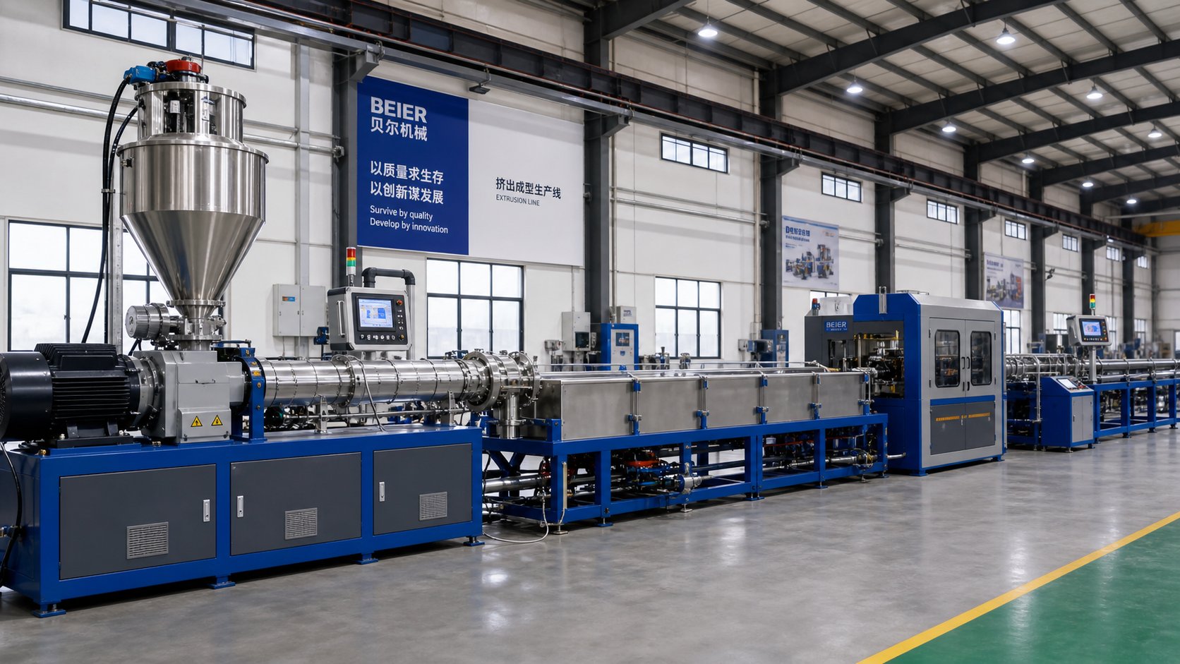
Selecting and Configuring a Single Screw Extrusion Line
Screw geometry, barrel metallurgy, zone mechanics, material behavior, wear patterns — you've absorbed a significant amount of technical knowledge up to this point. The challenge shifts now from understanding the machine to making a decision: which machine, which configuration, and what else goes around it? Every extrusion line purchase that disappoints can usually be traced back to a mismatch between what the buyer specified and what the application actually demanded. Translating technical knowledge into a disciplined selection process prevents that mismatch before a purchase order is signed.
Key Factors for Selecting the Right Single Screw Extruder
Walk into any trade show or browse listings for a plastic extruder for sale, and you'll find dozens of machines that look functionally identical on paper. The differences that matter live in the details — and evaluating those details requires a structured framework, not a spec sheet comparison. Here's a prioritized decision sequence that moves from the non-negotiable constraints inward to the optimization variables:
- Define the product and its geometry. Pipe, film, sheet, profile, wire coating, or pelletizing? The product dictates the die type, downstream equipment, and the screw design parameters that must be locked in before anything else. A facility shopping for an extruder for sale without first defining the product geometry is shopping blind.
- Identify the material and formulation. As the polymer-specific section of this guide made clear, every resin demands a different compression ratio, barrel metallurgy, and temperature management strategy. PVC and HDPE can't share a screw. PET requires pre-drying infrastructure. Filled compounds demand bimetallic barrels. Material choice constrains nearly every hardware decision downstream.
- Establish throughput requirements. Target output in kilograms per hour sets the screw diameter and drive power. Published vendor data shows indicative bands — a 60 mm screw typically delivers around 200 kg/h, while a 90 mm screw can reach 600 kg/h on PP — but these are material-dependent starting points, not guarantees. Always confirm sizing with a trial run on your actual resin.
- Evaluate energy efficiency and total cost of ownership. The plastic extruder machine price on the quote is the smaller half of the lifetime cost. Drive efficiency (servo vs. older DC systems), barrel insulation quality, heater technology, and cooling system design all compound into operating costs that dwarf the purchase price over a machine's 15-20 year service life. An efficient drive package pays back every shift, as energy research on polymer extrusion has confirmed.
- Assess available floor space and infrastructure. Complete extrusion lines can extend 20-40 meters depending on the product. Upstream material handling needs vertical clearance for silos and conveying. Downstream cooling tanks, pullers, and cutters need unobstructed run-out space. Verify that utilities — electrical capacity, cooling water supply, compressed air — can support the line's demands before committing to a machine size.
- Factor in maintenance access and spare parts availability. A machine with a lower extruder machine price but no local spare parts support becomes the most expensive option the first time a barrel liner fails and production stops for two weeks waiting on a shipment. Score vendors on after-sales response, wear parts lead time, and technical support — not headline price alone.
Whether you're evaluating new extruders for sale or considering a used extruders for sale listing to stretch a capital budget, this sequence applies equally. A used machine at an attractive extruder machine price still needs its screw, barrel, and drive system matched to your specific product and material — and the cost of correcting a mismatch after installation almost always exceeds the savings that motivated the purchase.
Building a Complete Extrusion Line
Here's a reality that surprises many first-time buyers: the extruder itself is often less than 30% of the total line cost. Without the upstream and downstream equipment that feeds it and processes its output, even the finest single screw extruder produces nothing usable. As Conair's extrusion processing guide puts it, auxiliary equipment is vital to every phase of the process — from receiving and storing raw material to measuring, cutting, and collecting finished product.
Upstream equipment prepares and delivers material to the extruder:
- Material storage and conveying — Silos, surge bins, and vacuum conveying systems move resin from receiving to processing. High-volume lines may require railcar or truck unloading systems capable of transferring bulk resin over distances up to 300 meters. Conveying speed matters — excessive velocity damages pellets and creates fines that degrade extrudate quality.
- Dryers — Mandatory for hygroscopic resins like PET, PC, nylon, and ABS. Central desiccant dryers, machine-side units, or mobile systems remove internal moisture to prevent hydrolysis, voids, and surface defects. Even non-hygroscopic resins benefit from drying as a temperature homogenization step — feeding the extruder material at a consistent temperature improves output stability regardless of season.
- Gravimetric blenders and feeders — Precisely meter virgin resin, regrind, colorant, and additives by weight into consistent recipes. Gravimetric systems eliminate the bulk density variability that causes output fluctuations with volumetric feeding, particularly important when incorporating recycled material with inconsistent particle geometry.
Downstream equipment transforms hot extrudate into finished product:
- Calibration and cooling — Vacuum sizing tanks for pipe and tubing, polished chill rolls for sheet and cast film, air rings for blown film. Temperature control units supply tempered coolant at precise, stable temperatures to maintain consistent heat transfer rates.
- Pullers and haul-offs — Motorized belt or track systems that draw extrudate through downstream equipment at precisely controlled speed. Fine adjustments in puller speed directly control wall thickness, diameter, and other dimensional features of the finished product.
- Cutters, saws, and winders — Cut-to-length systems for pipe, profile, and sheet; coilers for film and flexible tubing. Many operate on moving tables synchronized to line speed for clean, particle-free cuts during continuous operation.
- In-line measurement systems — Laser gauges, ultrasonic thickness sensors, and diameter measurement devices that feed real-time dimensional data back to the master extrusion control for automatic adjustment. These systems are what make a +/-0.5% gauge tolerance achievable without constant operator intervention.
- Granulators and scrap recovery — In-line or machine-side size reduction equipment that granulates edge trim, rejected sections, and startup scrap for immediate reprocessing. Closed-loop scrap recovery maximizes material utilization and reduces waste cost.
Matching barrel and screw specifications to the specific line application is where many facilities either get it right from the start or spend months chasing problems after commissioning. A pipe line running HDPE needs a high-compression barrier screw in a bimetallic barrel. A film line processing LDPE requires different channel depths, a different compression profile, and potentially different barrel metallurgy. A recycling line handling mixed post-consumer waste demands the most aggressive wear protection available. Each application is a distinct engineering problem, and the barrel-screw combination is its central variable.
For plants configuring new lines or upgrading existing ones — whether for pipe, film, sheet, pelletizing, recycling, or general-purpose production — NANHAIYA's single screw barrel solutions offer bimetallic and nitrided options engineered to match these diverse processing requirements. Evaluating a barrel supplier alongside the extruder manufacturer, die vendor, and downstream equipment provider ensures that every component in the line works as a coordinated system rather than an assembly of mismatched parts. When browsing a plastic extruder machine for sale or comparing an extruder machine for sale against alternatives, factor barrel sourcing into the total configuration — it's one of the easiest components to get wrong and one of the most consequential to get right.
Understanding screw design, zone mechanics, material behavior, and maintenance practices transforms a single screw extruder from a simple machine into a precision manufacturing tool — and the engineers who master these fundamentals consistently outperform those who treat the extruder as a black box.
Frequently Asked Questions About Single Screw Extruders
1. What are the three zones of a single screw extruder and what does each one do?
The three zones are the feed zone, compression zone, and metering zone. The feed zone uses deep screw channels to accept pellets or powder and convey them forward through a friction-driven mechanism where barrel-wall friction must exceed screw-surface friction. The compression zone gradually reduces channel depth to compact solids against the heated barrel wall, generating a melt film that grows as the solid bed shrinks — a process governed by drag-induced melting principles. The metering zone features the shallowest channels and acts as a precision pump, balancing drag flow and pressure flow to deliver stable, uniform pressure to the die. Product dimensional consistency depends heavily on metering zone stability, making it the final quality gatekeeper in the extrusion process.
2. How do I choose between a single screw extruder and a twin screw extruder?
The decision hinges on two core questions: what form is your feedstock in, and does the extruder need to perform the mixing? If you are processing pre-compounded pellets into products like pipe, film, sheet, or profiles, a single screw extruder is typically more economical, simpler to maintain, and delivers excellent pressure generation for die feeding. Twin screw extruders are the better choice when the machine itself must compound base resins with fillers, pigments, or additives, or when processing powders, performing reactive extrusion, or devolatilizing moisture-sensitive formulations. Single screw systems also offer lower capital cost and energy consumption for steady-state operations, while twin screw systems justify their higher price through superior dispersive and distributive mixing capabilities.
3. What compression ratio should I use for different polymers on a single screw extruder?
Compression ratio — feed channel depth divided by metering channel depth — must match the polymer's crystalline structure and thermal sensitivity. Crystalline polymers with sharp melting points need aggressive ratios: HDPE and PP typically require 3:1 to 4:1, while PA66 may need up to 3.7:1 to overcome its high heat of fusion. Heat-sensitive materials like rigid PVC in granule form work best at 2:1 to 2.5:1 to prevent degradation, though PVC powder needs a higher 3:1 to 4:1 ratio for densification. Amorphous resins such as ABS and polycarbonate soften gradually and perform well with gentler ratios of 1.6:1 to 3:1. Mismatching compression ratio to material is one of the most common causes of melt quality problems and thermal degradation in extrusion.
4. What causes output surging in a single screw extruder and how do I fix it?
Surging — cyclical fluctuations in output rate, die pressure, and motor load — most often traces back to disrupted solids conveying in the feed zone. The top causes include an overheated feed casing where cooling channels have become blocked with scale or rust, excessive screw temperature in the feed section that increases retarding friction, barrel zone 1 set outside the resin's optimal friction-stress temperature, and worn screw flights or barrel bore that allow melt leakage over flights. Start diagnosis by checking feed casing temperature (it should feel warm, not hot), verifying screw cooling flow, adjusting zone 1 setpoint, and measuring screw-to-barrel clearance. If a gear pump is installed, monitor screw RPM and motor current rather than downstream pressure, since the pump can mask surging while the screw speed oscillates to compensate.
5. How often should I inspect and replace the screw and barrel on a single screw extruder?
Inspection frequency should be based on operating hours rather than calendar dates. A practical schedule includes measuring screw flight diameters every 2,000 to 4,000 hours — focusing on the compression and metering zones — and measuring barrel bore diameter at 6 to 8 positions every 4,000 to 8,000 hours. Track indirect indicators continuously: declining output at constant RPM, rising motor amperage, increased pressure fluctuations, and climbing melt temperatures all signal progressive wear. Refurbishment is cost-effective when wear is limited to flight lands and base metal remains sound — PTA welding with nickel-tungsten-cobalt alloys can more than double service life. Full replacement is necessary when root diameter wear has altered the compression ratio, cracking has developed, or the screw design no longer matches the current material. Suppliers like NANHAIYA (nhyscrew.com) offer bimetallic and nitrided barrel replacements engineered for specific applications including pipe, film, sheet, pelletizing, and recycling lines.
Written by
Nanhaiya Technical Team
Zhoushan Nanhaiya Plastic Machinery Co., Ltd.
The Nanhaiya technical team supports screw and barrel manufacturing projects through application review, technical communication, custom manufacturing coordination, and production and quality control.
Discuss Your Application
Related Articles
More insights on screw barrel technology and plastics processing.

What Nobody Tells You About Screw Barrel For Plastic Machine Design
Oct 10, 2026
Learn how screw barrel for plastic machine design affects melt quality, throughput, and wear life. Covers geometry, resin matching, troubleshooting, and sourcing.
Read Article
Single Screw Extruder for Sheet: Stop Guessing, Start Specifying
Oct 9, 2026
Learn how to specify a single screw extruder for sheet production. Covers screw geometry, resin-specific processing, troubleshooting, and maintenance best practices.
Read Article
PE Pipe Extruder Machine: What Datasheets Won't Tell You
Oct 9, 2026
Learn how a PE pipe extruder machine works, key specs explained, material grade selection, maintenance tips, and buyer guidance beyond the datasheet.
Read ArticleLooking for something else?
Search by material, symptom or product and jump straight to the relevant page.
These are navigation suggestions based on keyword matching — not a quotation, not a delivery commitment, and not a substitute for engineering review. Final specification is confirmed by our engineers against your drawings and processed material.
Need help with screw barrel selection?
Share your machine model, processed material and application. Our team can help with pricing and technical support.