

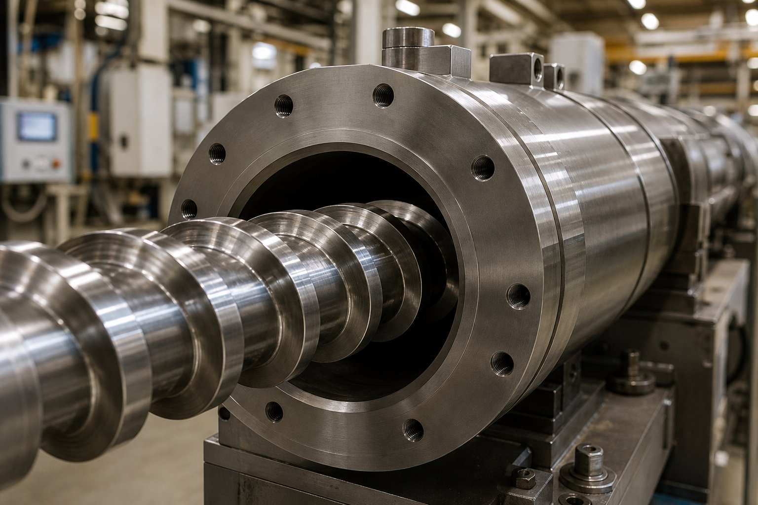
What Is a Single Screw Barrel and Why It Matters
Imagine a component so central to plastics manufacturing that its design alone determines whether your production line delivers flawless output or costly rejects. That component is the single screw barrel — and most engineers underestimate its influence on everything from melt quality to energy consumption.
A single screw barrel is a precision-machined cylindrical steel housing within which a helical screw rotates to convey, compress, melt, and meter polymer material into a uniform pressurized melt stream suitable for extrusion through a shaping die.
Defining the Single Screw Barrel
At its core, the system consists of two elements working in concert. The barrel itself is a hardened steel cylinder fitted with multiple heating and cooling zones along its length. Inside, an extruder screw — a shaft with precisely machined helical flights — rotates to move material forward. Together, they form the processing heart of any single screw extruder.
The barrel maintains tight bore tolerances to control the clearance between its inner wall and the screw flights. This gap, often just fractions of a millimeter, directly affects melting efficiency, pressure generation, and output consistency. The barrel's outer surface houses electric heaters and cooling systems that provide zone-by-zone thermal control, typically managed through PID controllers for accuracy within ±1°C.
Why This Component Matters in Plastics Processing
The barrel-screw system converts raw polymer pellets, flakes, or powders into a homogeneous, pressurized melt ready for shaping. You'll find this screw extruder configuration responsible for the vast majority of extruded plastic products worldwide — from HDPE water pipes and PVC window profiles to packaging films, thermoforming sheets, and recycled pellets.
Barrel and screw selection directly governs four critical outcomes: output rate, melt quality, energy efficiency, and product consistency. A poorly matched system wastes energy, degrades polymer, and limits throughput. The right configuration, however, unlocks stable production across applications including pipe, film, sheet, profiles, pelletizing, and recycling lines.
What makes selection so challenging is the sheer number of variables involved — geometry, metallurgy, surface treatments, and application-specific demands all intersect. Understanding how these elements interact starts with grasping the fundamental mechanics of how material actually moves and transforms inside the barrel.
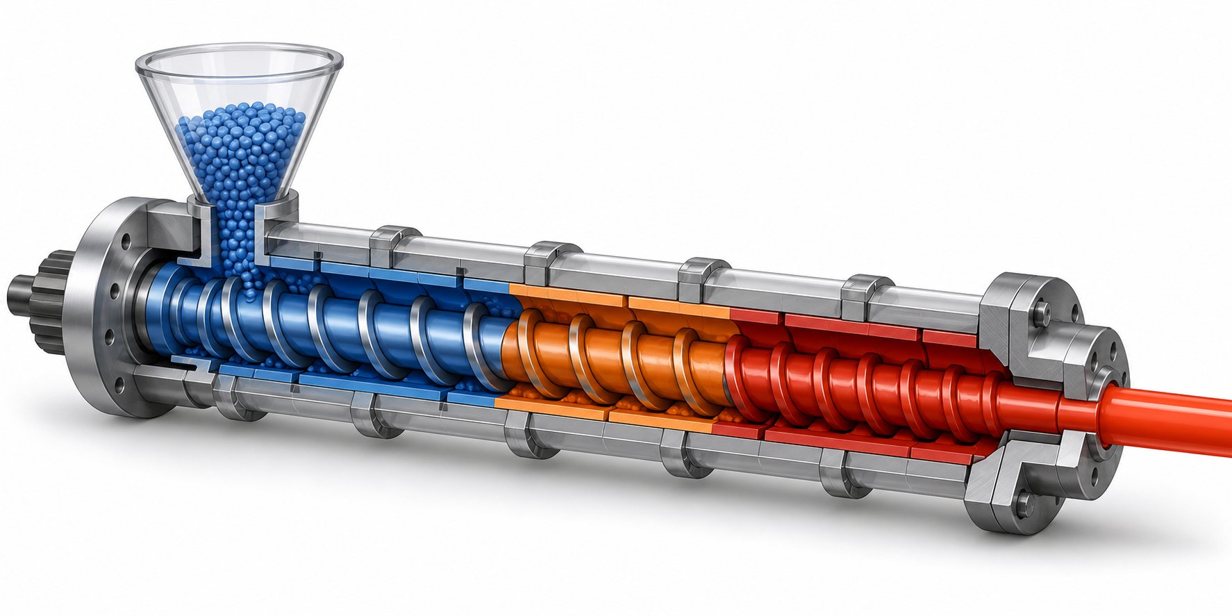
How the Three Functional Zones of Single Screw Extrusion Work Together
Picture a polymer pellet entering one end of the barrel and emerging as a perfectly homogeneous melt at the other. That transformation doesn't happen all at once — it unfolds across three distinct functional zones, each engineered to accomplish a specific task. Every single extruder screw divides its working length into a feed zone, a compression zone, and a metering zone. Understanding what happens in each zone is the key to diagnosing problems and selecting the right geometry for your application.
Feed Zone and Solids Conveying
Raw polymer enters through the barrel's feed throat — a machined opening typically fitted with a water-cooled jacket to prevent premature melting that would bridge the inlet. The screw flights in this section have their deepest channel depth, creating maximum volume to accept bulk pellets, flakes, or powder.
Rotation of the screw pushes material forward through frictional drag between the polymer and the barrel wall. Here's the critical detail: the polymer must stick to the barrel and slip on the screw root for efficient conveying. That's why feed throat cooling matters — it keeps the barrel surface just warm enough for adhesion without softening the pellets into a sticky mass.
For slippery, hard polymers like high-density polyethylene, grooved feed barrel sections dramatically improve solids conveying. These axial or helical grooves, machined into a separately water-cooled feed zone, decouple throughput from screw speed by mechanically gripping the pellets and forcing them forward independent of friction alone.
Compression and Transition Zone
As material advances, the channel depth gradually decreases — imagine the walls closing in on the polymer bed. This reduction in volume accomplishes three things simultaneously: it consolidates loose particles into a dense mass, expels trapped air back toward the feed throat, and initiates melting through intense viscous shear against the barrel wall.
The compression ratio — the volume of the first flight divided by the volume of the last — typically falls between 2:1 and 4:1. Semi-crystalline polymers like polyethylene and nylon, which undergo a sharp solid-to-liquid transition, generally require higher compression ratios (3:1 to 4:1). Amorphous materials like polystyrene and polycarbonate soften more gradually and perform well with lower ratios (2:1 to 2.5:1).
The screw extrusion process leverages decreasing channel depth to force unmelted polymer closer to the barrel surface, where shear rates are highest. A thin melt film forms on the barrel wall, gets sheared by relative rotation, and progressively consumes the solid bed from the outside in.
Metering Zone and Melt Delivery
By the time polymer reaches the metering zone, it should be fully or nearly fully melted. This final section features a constant, shallow channel depth that serves two purposes: homogenizing the melt temperature and building the pressure necessary to push material through the die.
Metering zone length and channel geometry directly control melt temperature uniformity and output stability. A longer metering section provides more residence time for thermal equalization, while a shallower channel increases shear mixing but also adds heat. Getting this balance right is what separates a well-designed single screw extrusion system from one that produces inconsistent output or overheated melt.
Approximately 85-90% of drive power in a single-screw extruder goes directly to melting polymer through viscous shear — barrel heaters contribute almost nothing once screw rotation begins and are often in cooling mode during steady-state operation.
This counterintuitive reality, well documented in plastics engineering literature, means the screw's mechanical design — not the heater bands — is the primary driver of melt quality. The rotational energy from the drive motor converts to thermal energy as it shears viscous polymer, particularly in the compression and metering zones where channel depths are shallowest.
For process engineers, this principle has a direct practical implication: when melt temperature runs too high, the answer usually lies in screw geometry or speed adjustments rather than simply turning down barrel heaters. And when specifying a new barrel-screw system, the design parameters governing these three zones — channel depths, compression ratio, and metering length — matter far more than heater wattage alone.
Key Design Parameters and Extruder Barrel Specifications
Screw geometry and zone design tell you how polymer transforms inside the barrel. But the specification sheet tells you what you're actually buying — and surprisingly few resources lay out those numbers in a way that engineers and procurement teams can quickly compare. Here's a structured breakdown of the parameters that define every single screw barrel system, from laboratory-scale R&D units to full-production extrusion lines.
Diameter Ranges and Screw Barrel L/D Ratio
Screw diameter is the single most important sizing parameter for any single screw extruder machine. It determines throughput capacity, torque requirements, and the physical scale of the entire extrusion line. Industry-standard diameters follow a serialized progression — commonly 30 mm, 45 mm, 65 mm, 90 mm, 120 mm, 150 mm, and 200 mm, with custom sizes reaching 300-400 mm for specialized high-output applications. The most widely used range for production extrusion falls between 65 mm and 150 mm. Smaller diameters (16-45 mm) serve laboratory development, pilot lines, and low-volume specialty applications, while bores above 150 mm handle heavy-duty pipe production, thick sheet lines, and high-throughput pelletizing systems.
The L/D ratio — the ratio of effective screw length to its diameter — is equally consequential. Imagine two screws with identical 90 mm diameters: one at 24:1 L/D measures 2,160 mm in working length, while a 32:1 version stretches to 2,880 mm. That additional 720 mm of processing length translates to longer residence time, more thorough melting, and better melt homogeneity — but it also increases shear energy input, machine footprint, and cost.
How do you choose the right ratio? It depends on how much work the polymer needs. Standard polyolefins like HDPE and PP plasticize well at L/D ratios of 20:1 to 25:1. PVC profiles, ABS, and engineering plastics that demand better mixing typically require 28:1 to 30:1. Compounding operations, masterbatch production, and vented degassing applications push the ratio to 32:1 or even 36:1, where the extra length accommodates additional mixing elements or a two-stage decompression zone.
The table below consolidates the core specification categories you'll encounter when evaluating any single screw extruder machine, populated with general industry ranges drawn from established manufacturing standards:
| Specification | Standard Range | Extended / Custom Range | Notes |
|---|---|---|---|
| Screw Diameter | 25 - 200 mm | 200 - 400 mm | Serialized sizes: 30, 45, 65, 90, 120, 150, 200 mm most common |
| L/D Ratio | 20:1 to 30:1 | 32:1 to 36:1 (up to 40:1) | Higher L/D improves mixing but increases shear energy input |
| Compression Ratio | 1.8:1 to 3.5:1 | 3.5:1 to 4.5:1 | Semi-crystalline polymers (HDPE, PP) use higher ratios; amorphous (PS, ABS) use lower |
| Screw Speed Range | 20 - 150 RPM | Up to 250+ RPM (high-speed film lines) | Optimal speed depends on diameter, polymer viscosity, and cooling capacity |
| Drive Power | 5 - 250 kW | Up to 500+ kW for large-bore systems | Proportional to diameter cubed and screw speed |
| Typical Throughput | 20 - 800 kg/hr | 1,000+ kg/hr for large-diameter production | Varies significantly with polymer type, L/D, and screw design |
| Screw-to-Barrel Clearance | 0.05 - 0.10 mm (< 80 mm dia.) | 0.08 - 0.15 mm (> 80 mm dia.) | Clearance growth beyond 0.2-0.3 mm signals wear-driven output loss |
| Max Operating Temperature | Up to 350°C | Up to 450°C (barrel wall) | Application-dependent; PVC ~180°C, engineering plastics ~320°C |
You'll notice compression ratio appears alongside L/D because they work in tandem. A 24:1 barrel with a 3.5:1 compression ratio behaves very differently from a 30:1 barrel at the same ratio — the longer barrel spreads the compression over more flights, producing gentler shear and lower peak melt temperatures. Matching both parameters to your specific polymer family is where the real engineering begins.
Material Grades and Tolerance Standards
The steel beneath the surface treatment determines a barrel's structural integrity, machinability, and nitriding response. The global standard for nitrided plasticating barrels and screws is 38CrMoAl (DIN 1.8509) — an alloy steel with high chromium, molybdenum, and aluminum content specifically chosen for its excellent nitrogen affinity during case hardening. This steel accepts deep, uniform nitrided layers that other alloy grades simply cannot match. Alternative barrel shell materials include 42CrMo4 for standard-duty applications, while screw bodies may use 4140, H13, or D2 tool steel depending on torque and wear requirements.
For barrels destined for corrosive or abrasive service, the shell material matters less than the bore lining. Bimetallic barrels use centrifugal casting to apply a 1.5-3.0 mm wear-resistant alloy liner — typically a boron-nickel-chromium-tungsten matrix — inside a conventional alloy steel shell. This construction delivers bore hardness of 950-1,100 HV, far exceeding the approximately 68 HRC (roughly 900-1,050 HV equivalent) benchmark often cited in product specifications for standard nitrided barrels.
Why does 68 HRC matter? It represents a solid baseline for processing standard polyolefins and unfilled engineering resins. But here's what product catalogs rarely explain: hardness alone doesn't predict barrel life. A nitrided barrel at 1,050 HV has a wear-resistant layer only 0.4-0.6 mm deep. Once abrasive fillers or corrosive gases eat through that thin shell, the soft substrate underneath wears rapidly. A bimetallic barrel at similar hardness provides 1.5-3.0 mm of protection — effectively three to six times the wear reserve before the barrel reaches end-of-life.
Dimensional tolerances are equally critical, yet often overlooked during procurement. Precision manufacturing holds bore roundness below 0.015 mm and screw OD tolerance to ±0.01 mm. These tight figures ensure proper screw-to-barrel clearance across the full barrel length. When bore straightness drifts or roundness opens up, the clearance becomes uneven — accelerating localized wear, creating hot spots from polymer stagnation, and allowing increased melt back-flow that degrades output volumetric efficiency. A surface roughness target of Ra ≤ 0.4 µm on the honed bore minimizes polymer adhesion and reduces color-change purge time.
Selecting the right combination of material grade, surface treatment, and tolerance class isn't a one-size-fits-all decision. It hinges entirely on what polymer you're running and what conditions it creates inside the barrel — which is exactly why specialized screw geometries exist to handle the wide range of processing challenges different applications present.
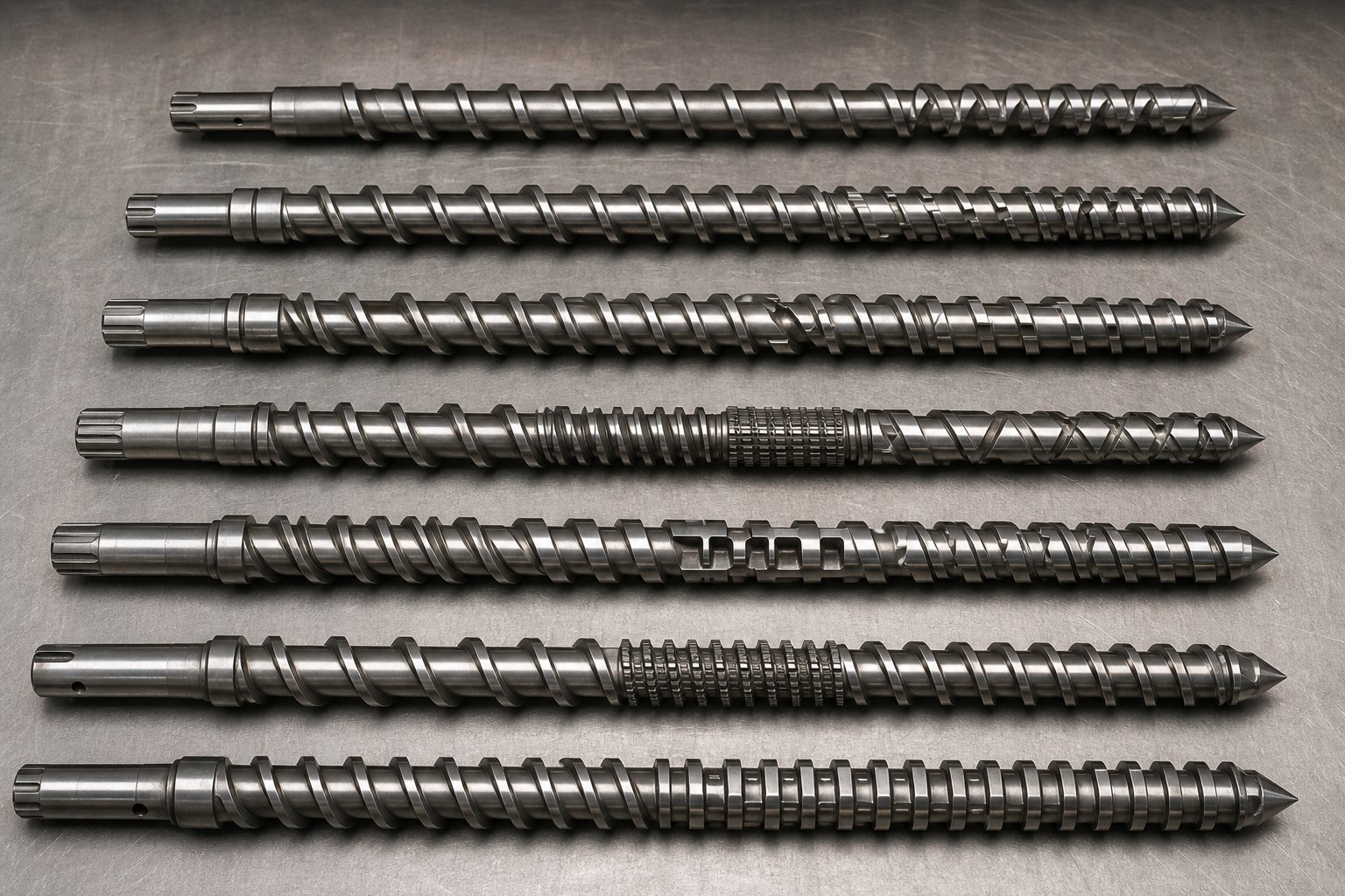
Specialized Screw Geometries and When to Use Them
Product catalogs are full of names — barrier, vented, grooved-feed, Maddock — yet rarely explain what each design actually does inside the barrel or why you'd choose one over another. That gap between marketing labels and engineering reality costs processors real money when the wrong geometry lands on their production floor. Let's fix that.
Barrier Screws and Melt Separation
A conventional three-zone screw relies on a single helical flight to simultaneously convey, compress, and melt polymer. It works well for straightforward applications, but it has a fundamental limitation: nothing physically prevents partially melted material from reaching the metering zone. At higher output rates or with hard-to-melt resins, unmelted pellets — visible as "fisheyes" or gels — slip through.
The barrier screw design solves this by introducing a secondary flight in the compression zone. This additional flight divides the screw channel into two parallel paths: a solids channel and a melt channel. As polymer melts against the barrel wall, the resulting melt film flows over the barrier flight — whose clearance is intentionally tighter than the main flight — into the dedicated melt channel. Unmelted pellets, too large to pass over the barrier, remain confined in the solids channel until they fully plasticize.
The result is remarkably effective. Because the solids channel shrinks to nothing by the end of the barrier section, essentially no unmelted polymer can reach the metering zone. You get more complete melting, more stable output, and reduced surging — all without raising barrel temperatures or sacrificing throughput.
When does a barrier screw design earn its place over a conventional metering screw? Consider it whenever you're running a plastic single screw extruder at high output rates, processing broad-melting-range polymers, or producing film, thin sheet, or fiber where even a single unmelted particle creates a visible defect. The trade-off is cost and material specificity: barrier screws are more expensive to manufacture and are best designed for a particular polymer family rather than used as a general-purpose replacement.
Vented Screws for Degassing Applications
Some polymers carry moisture, trapped air, or volatile compounds that must escape before the melt reaches the die. Hygroscopic resins like PET and nylon absorb atmospheric moisture that causes hydrolytic degradation during processing. Recycled feedstocks introduce residual solvents, printing inks, and decomposition gases. Drying systems help, but they add cost, floor space, and energy — and sometimes they simply aren't enough.
A vented extruder screw addresses this problem directly inside the barrel. The concept uses a two-stage design: the first stage melts and compresses polymer just like a conventional screw. Then the channel depth suddenly increases in a decompression zone, dropping melt pressure close to zero. At this low-pressure point, a vent port machined into the barrel allows moisture and volatiles to escape — either to atmosphere or through an applied vacuum for more aggressive degassing.
Beyond the vent, a second-stage recompression section re-pressurizes the now-degassed melt and meters it to the die. The critical engineering challenge here is balancing the two stages so melt doesn't flood backward through the vent port — a problem called "vent flow" that contaminates the vacuum system and shuts down production. Proper decompression zone depth and second-stage pumping capacity must be carefully matched to the polymer's viscosity and the target throughput.
Vented designs are standard for PET sheet and strapping lines, recycled polyolefin pelletizing, and any application where downstream product quality depends on removing trapped gases that would otherwise cause bubbles, porosity, or poor surface finish.
Groove-Feed and Mixing Screw Designs
Conventional feed zones rely entirely on friction between the polymer and the barrel wall to push material forward. For slippery polymers like HDPE and PP, this friction-dependent conveying creates a problem: throughput becomes sensitive to screw speed, melt temperature, and even ambient temperature fluctuations. Small changes in any variable cause output drift.
Grooved feed barrel sections eliminate this instability. Axial or helical grooves machined into a separately water-cooled feed zone mechanically interlock with the pellets, gripping them and forcing them forward regardless of frictional conditions. The result is throughput that remains remarkably consistent and largely independent of screw speed — a significant advantage for tight-tolerance products like precision pipe and medical tubing.
Mixing elements address a different challenge entirely: homogenizing additives, colorants, and fillers within the melt. A standard metering zone provides minimal distributive mixing, which is fine for natural resin but inadequate the moment you add pigment or filler. Extrusion authority Jim Frankland notes that the choice between dispersive and distributive mixing sections is one of the most consequential — and most frequently misunderstood — decisions in screw specification.
Here's the practical distinction. Dispersive mixers like the Maddock (also called a fluted or Union Carbide mixer) force melt through a narrow clearance gap under high shear, breaking apart hard agglomerates such as pigment clumps and unmelted gels. Distributive mixers — pin sections, pineapple elements, and Saxton designs — repeatedly divide and recombine the melt stream with minimal added shear, spreading material evenly without generating excessive heat. For barrier screws that already handle melting efficiently, distributive mixers are usually the better pairing, since the barrier section has already completed melting and additional high-shear mixing would needlessly raise melt temperature.
The following summary maps each geometry to its primary strength and best-fit scenario:
- Barrier screw — Primary advantage: forces complete melting by separating solids from melt pool. Ideal for high-output film, sheet, and pipe lines processing polyolefins and engineering resins where unmelted particles are unacceptable.
- Vented (two-stage) screw — Primary advantage: removes moisture and volatiles directly during extrusion without pre-drying. Ideal for recycled feedstocks, PET, nylon, and any hygroscopic polymer where trapped gases cause bubbles or degradation.
- Grooved-feed barrel section — Primary advantage: decouples throughput from friction, delivering consistent solids conveying. Ideal for HDPE, PP, and other slippery polyolefins on precision pipe and profile lines.
- Maddock (fluted) mixer — Primary advantage: high-shear dispersive action breaks hard agglomerates like pigment clumps and gels. Ideal for masterbatch letdown and applications requiring aggressive particle size reduction.
- Pin mixer — Primary advantage: low-shear distributive mixing spreads additives evenly without overheating. Ideal for shear-sensitive polymers (PVC, certain bioplastics) and even blending of liquid additives.
- Pineapple mixer — Primary advantage: moderate-shear chaotic mixing through intersecting channels. Ideal for general-purpose color blending and applications needing a balance between dispersion and temperature control.
Choosing the right geometry — or the right combination, since a high-performance screw can pair a barrier section with a distributive mixer — depends entirely on what's limiting your current process. Is it incomplete melting? Look at barrier designs. Moisture or volatiles? Consider a vented configuration. Poor color or additive dispersion? Add the appropriate mixing element. The screw type sets the ceiling on what your extrusion line can achieve, and no amount of temperature or speed adjustment can compensate for a geometry mismatch.
Of course, even the most sophisticated screw geometry performs only as well as the barrel environment surrounding it — which is why matching these designs to specific application industries and their unique processing demands is equally important.
Application Industries and Single Screw Extrusion Machine Design Requirements
Barrier flights, mixing sections, vented stages — each geometry was engineered to solve a specific processing problem. But the real question on any production floor isn't "which screw type exists?" It's "which one does my application actually need?" The answer varies dramatically across industries, because a pipe line and a blown film tower place fundamentally different demands on the barrel-screw system, even when both run the same polymer family. Here's where theory meets the shop floor.
Pipe and Profile Extrusion
Walk through any pipe manufacturing facility and you'll notice something telling: virtually every line runs a single screw plastic extruder. It's not by accident. Pipe production — whether HDPE water mains, PVC drain systems, or PP industrial piping — depends on steady-state pressure generation and consistent melt delivery over extended production runs that may last days or weeks without interruption. The single-screw platform excels here precisely because its operating principle delivers inherently stable, pulsation-free output once the process reaches equilibrium.
What specific barrel and screw features make this work? Start with L/D ratio. Pipe lines typically specify 30:1 or higher because longer processing length gives the metering zone more time to homogenize the melt. Imagine squeezing toothpaste from a tube — the longer the channel, the more uniform the stream becomes. For a thick-walled HDPE pressure pipe where even minor melt-temperature gradients create residual stress and reduce long-term hydrostatic strength, that extra homogenization isn't optional.
Metering zone design is equally critical. Pipe screws often dedicate 30-40% of their total length to the metering section — substantially more than general-purpose designs. This elongated metering zone ensures the entire cross-section of the melt reaches a uniform temperature before entering the pipe die, which directly governs wall-thickness consistency and dimensional stability. For PVC pipe, where the processing window between fusion and degradation is notoriously narrow, barrel zone temperature control must hold ±2°C across every heating zone. Any wider variation risks thermal degradation that weakens the pipe or incomplete gelation that leaves it brittle.
Grooved-feed barrel sections have become standard on polyolefin pipe lines specifically because they decouple throughput from back-pressure fluctuations at the die. When you're producing pipe to tight dimensional tolerances over a 24-hour run, output stability isn't a nice-to-have — it's the difference between saleable product and scrap.
Film, Sheet and Blown Film Lines
If pipe extrusion demands consistency, film production demands perfection. A 25-micron blown LDPE film has almost zero margin for melt-temperature variation: just a few degrees of non-uniformity across the annular die gap creates gauge bands — visible thickness variations that render the film unsaleable for packaging applications.
This extreme sensitivity to thermal uniformity shapes every aspect of barrel and screw design for film lines. Screws optimized for low-melt-temperature polymers like LDPE and LLDPE typically use moderate compression ratios (2.5:1 to 3.0:1) combined with barrier flight sections to ensure complete melting without excessive shear heating. The goal is to deliver a fully plasticized melt at the lowest possible temperature — typically 190-210°C for LDPE — because every unnecessary degree adds cooling cost downstream and risks degradation.
Barrel zone temperature strategy differs from pipe as well. Film extruders often run barrel heaters in cooling mode across the compression and metering zones during steady-state operation, because viscous shear generates more heat than the process needs. Nordson Xaloy's process engineering team emphasizes that successful screw design for film takes into account the polymer's bulk density, frictional properties, specific heat, and viscosity curve — not just generic geometry ratios. Their approach draws on decades of rheological data to predict temperature rise through computer simulation, optimizing the balance between shear heating and barrel cooling to hit target melt temperatures with minimal variability.
Mixing elements take on heightened importance for film applications. Gels — those pinpoint-sized defects visible against light — are the bane of film producers. They can originate from unmelted resin, crosslinked polymer, or degradation products, and each root cause requires a different response. For high-output blown film lines, barrier screws paired with dispersive mixing sections (such as the Maddock mixer) provide the most reliable defense against unmelt-related gels. The barrier section physically prevents solid pellets from reaching the metering zone, while the downstream mixer breaks apart any remaining agglomerates under controlled shear.
L/D ratios for film screws typically fall in the 24:1 to 30:1 range, with the higher end used for multi-layer coextrusion lines where each layer's single screw extrusion machine must deliver exact throughput to maintain layer-thickness ratios.
Pelletizing, Recycling and Compounding
Recycling and pelletizing lines inhabit a different world entirely. Instead of pristine virgin resin, a screw extruder granulator might process post-consumer HDPE bottles ground into irregular flakes, post-industrial PP regrind loaded with calcium carbonate filler, or mixed waste streams containing paper labels, adhesive residue, and metal fragments. Every one of these contaminants attacks the barrel bore.
Abrasive fillers and foreign particulates accelerate barrel wear at rates that would shock anyone accustomed to running clean resin. Industry experts Mark Spalding (Dow) and Tim Womer identify glass fibers, silica, and calcium carbonate as common abrasive fillers that cause particularly aggressive wear — especially in channel sections with high solids concentration, where particles can momentarily wedge and generate massive side forces that push screw flights into the barrel wall. In recycling applications, these wear mechanisms compound because the feedstock composition is inherently inconsistent: one batch of regrind may contain 5% mineral filler, the next 15%.
This is where bimetallic barrel linings earn their investment. A standard nitrided barrel processing filled recycled polyolefin might last 6-12 months before clearance growth degrades output beyond acceptable limits. A centrifugal-cast bimetallic barrel with a tungsten-carbide or nickel-boron alloy liner can extend that service interval to 2-4 years under the same conditions — dramatically reducing downtime and replacement costs.
Vented barrel configurations are equally essential for recycling. Post-consumer waste carries residual moisture, volatile organic compounds from printing inks, and decomposition gases from previous thermal cycles. Without degassing, these volatiles cause foaming, porosity, and surface defects in the pelletized output. Two-stage vented screws with vacuum-assisted vent ports strip out these contaminants during processing, eliminating or reducing the need for expensive upstream drying equipment. For heavily contaminated streams, dual-vent configurations — with two separate decompression-recompression stages — provide even more thorough volatile removal.
Compounding applications add yet another layer of complexity. Incorporating high loadings of mineral fillers, glass fiber, or flame retardants into a polymer matrix pushes both abrasive and corrosive wear mechanisms simultaneously. Flame-retardant compounds release hydrochloric or hydrobromic acid at processing temperatures, attacking even hardened barrel surfaces. For these environments, barrels with nickel-based corrosion-resistant alloy liners — not just abrasion-resistant linings — become necessary to prevent premature bore degradation.
The table below maps each major application against its key barrel-screw design requirements, giving you a practical reference for matching equipment specifications to your production environment:
| Application | Recommended L/D Ratio | Preferred Screw Type | Barrel Lining | Critical Performance Parameter |
|---|---|---|---|---|
| HDPE / PP Pipe | 30:1 to 33:1 | Barrier screw with extended metering zone; grooved-feed barrel | Nitrided (unfilled resin) or bimetallic (filled compounds) | Melt homogeneity and steady-state pressure stability |
| PVC Pipe and Profiles | 24:1 to 28:1 | Conventional metering screw with low compression ratio (1.8:1 to 2.2:1) | Bimetallic with nickel-alloy corrosion-resistant liner | Tight thermal control within narrow processing window |
| Blown Film (LDPE / LLDPE) | 24:1 to 30:1 | Barrier screw with dispersive or distributive mixing section | Nitrided or chrome-plated bore | Melt temperature uniformity and gel-free output |
| Cast Film and Sheet | 28:1 to 32:1 | Barrier screw with Maddock or pin mixer | Nitrided (standard) or bimetallic (filled sheet) | Gauge consistency and optical clarity |
| Recycled Polyolefin Pelletizing | 30:1 to 36:1 | Two-stage vented screw with vacuum port | Bimetallic with boron-nickel or tungsten-carbide alloy | Degassing efficiency and barrel wear resistance |
| Compounding (Filled / FR Systems) | 28:1 to 34:1 | Barrier or conventional with high-shear mixing elements | Bimetallic with corrosion-resistant nickel alloy | Filler dispersion and resistance to corrosive off-gases |
| Wire and Cable Coating | 24:1 to 28:1 | Conventional metering screw with moderate compression | Nitrided or bimetallic depending on compound | Concentricity of insulation layer and output consistency |
You'll notice a clear pattern: applications processing clean, unfilled polymers can often rely on nitrided barrels and simpler screw geometries, while recycling, compounding, and corrosive-compound processing demand bimetallic linings and more specialized designs. The cost differential between a nitrided and bimetallic barrel can be 2-3x, but in abrasive service, the nitrided option may need replacement three or four times before the bimetallic barrel reaches end-of-life — making the upfront premium a straightforward economic decision.
That cost-versus-longevity calculation brings up a broader question: how exactly do these surface treatments differ in performance, and which one actually matches your processing environment? The answer lies in understanding the metallurgy behind each option.
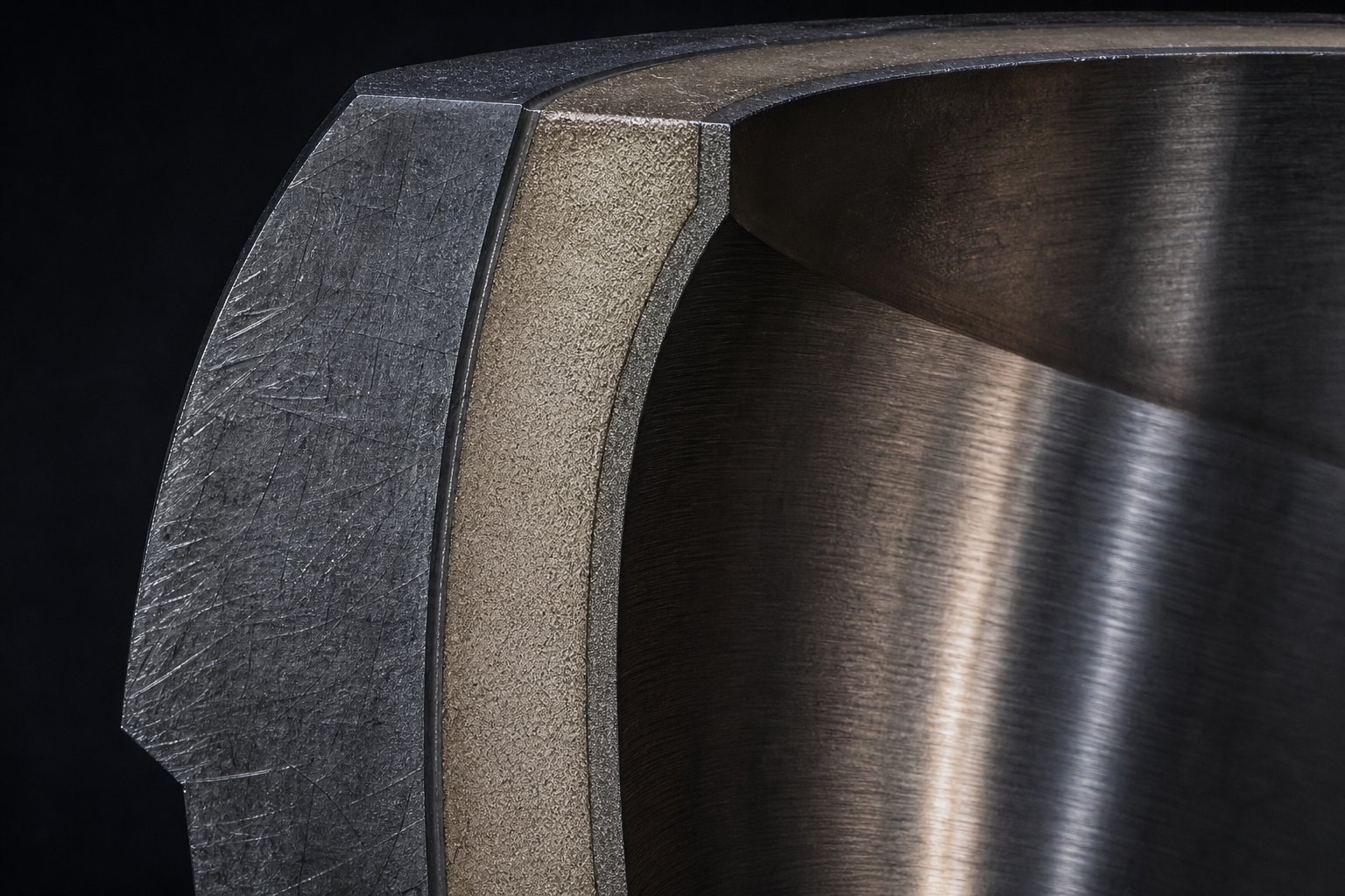
Surface Treatments and Extruder Barrel Wear Resistance Compared
Every polymer extruder barrel eventually wears out — that's inevitable. What's not inevitable is how fast it happens. The surface treatment you specify at purchase dictates whether your barrel lasts 12 months or 5 years under identical processing conditions. Yet most buyers default to whatever the supplier offers as standard without understanding the trade-offs. Here's the metallurgy stripped down to its practical essentials.
Nitriding and Case Hardening
Gas nitriding is the most widely used surface treatment for single screw barrel systems worldwide. The process diffuses nitrogen atoms into the barrel's base steel at elevated temperature (typically 500-550°C), forming a hard iron-nitride compound layer on the bore surface without adding any separate material. The resulting case depth runs approximately 0.4 to 0.7 mm, with surface hardness reaching 950-1,050 HV (roughly 65-70 HRC).
For clean, unfilled polymers — think natural PP, PE, PS, or ABS — a nitrided barrel on a base steel like 38CrMoAlA delivers reliable service at the lowest cost per unit. The hard case resists the mild sliding wear that standard resins create, and the economics make sense because you're not paying for protection the application never demands.
Where nitriding falls short is in two specific environments. First, abrasive fillers. Glass fiber, calcium carbonate, talc, and mineral reinforcements act like fine sandpaper against the bore surface. Because the nitrided case is thin — less than a millimeter — abrasive particles cut through it relatively quickly. Once they reach the softer core steel beneath, wear accelerates dramatically. Second, corrosive chemistry. Processing PVC releases hydrochloric acid at elevated temperatures. Flame-retardant compounds emit hydrobromic acid. Fluoropolymers generate hydrofluoric acid. Nitriding offers minimal defense against chemical attack, and a corroded barrel surface roughens rapidly, trapping degraded polymer and creating the black specks every processor dreads.
Bimetallic Barrel Linings and Their Performance
When the processing environment exceeds nitriding's protective limits, a bimetallic extruder barrel is the standard upgrade. "Bimetallic" means exactly what it sounds like: two metals working together. The outer shell remains conventional alloy steel for structural strength, while the bore receives a separate wear-resistant alloy lining applied through centrifugal casting.
The manufacturing process involves heating alloy powder inside a pre-bored barrel, then spinning it at high speed so molten alloy is forced against the inside wall, creating a dense, metallurgically bonded liner typically 1.6 to 3.0 mm thick. That's three to six times the depth of a nitrided case — a massive increase in wear reserve before the barrel reaches replacement threshold.
The alloy composition determines what the lining resists best:
- Iron-boron-nickel-chromium alloys — General-purpose wear grade. High hardness (HRC 58-62), strong abrasion resistance, best where corrosion isn't the primary threat. The workhorse choice for mineral-filled polyolefins and glass-reinforced engineering resins.
- Nickel-chromium-cobalt alloys — Corrosion-forward grade. Trades some abrasion resistance for superior chemical resistance. The go-to selection for PVC, fluoropolymers, and flame-retardant compounds that release aggressive acids.
- Tungsten-carbide-bearing alloys — Premium abrasion grade. Embedded carbide particles deliver the highest wear resistance available, with temperature tolerance up to 600°C. Reserved for the most punishing applications: heavily glass-filled compounds, recycled feedstocks with metal contamination, and high-temperature engineering polymers.
Is the investment justified? The calculus is straightforward. A bimetallic barrel typically costs 2-3x more than a nitrided equivalent. But in abrasive or corrosive service, the nitrided option may require replacement three to four times before the bimetallic unit reaches end-of-life. Factor in production downtime for each changeout — typically 8-24 hours including cool-down, removal, installation, and restart — and the bimetallic option often wins on total cost of ownership even with a higher sticker price.
Advanced Coatings and Surface Engineering
Beyond nitriding and bimetallic linings, several specialized surface technologies address niche requirements that neither standard approach fully covers.
Hard chrome plating applies a thin chromium layer (0.05-0.2 mm) to the barrel bore, providing excellent corrosion protection and a low-friction surface that resists polymer adhesion. It won't match bimetallic linings for abrasion resistance — the layer is simply too thin — but for corrosive-only environments where abrasive fillers aren't present, chrome plating delivers chemical protection at moderate cost. Film producers sometimes specify chrome-plated bores to minimize purge time during color changes, since the smooth chromium surface releases polymer residue more easily than nitrided steel.
PVD (Physical Vapor Deposition) coatings represent the emerging frontier. These vacuum-deposited ceramic layers — titanium nitride, chromium nitride, diamond-like carbon — achieve extreme surface hardness (up to 3,000 HV) in films just a few microns thick. Their current application in barrel bores remains limited due to the challenge of uniformly coating long internal surfaces, but they're gaining traction for screw flight tips and specific high-wear zones where localized protection extends component life without the cost of full bimetallic treatment.
The comparison table below organizes these options against the criteria that matter most when specifying extruder barrel wear resistance for your application:
| Treatment Type | Hardness Range | Abrasion Resistance | Corrosion Resistance | Relative Cost | Best-Fit Polymer Applications |
|---|---|---|---|---|---|
| Bimetallic — Iron-Boron-Nickel alloy | HRC 58-62 | High | Low to Moderate | High | Glass-filled engineering resins, mineral-filled polyolefins, recycled feedstocks with abrasive contamination |
| Bimetallic — Nickel-Chromium-Cobalt alloy | HRC 50-58 | Moderate | High | High | PVC, fluoropolymers, flame-retardant compounds, halogenated polymers |
| Bimetallic — Tungsten-Carbide-bearing alloy | HRC 55-60 | Very High | Moderate to High | Very High | Heavily glass-filled compounds (>30%), high-temperature engineering polymers, extreme abrasion environments |
| Gas Nitriding | HRC 65-70 (surface) | Moderate | Low | Low | Unfilled PP, PE, PS, ABS, and other clean non-abrasive polymers |
| Hard Chrome Plating | HRC 62-68 | Low to Moderate | High | Moderate | Corrosive resins without abrasive fillers, film applications requiring fast color changes |
| PVD Coatings (TiN, CrN, DLC) | HV 2,000-3,000+ | Very High (localized) | Moderate to High | Moderate to High | Screw flight tips, specialized wear zones, emerging barrel bore applications |
Notice how surface hardness numbers alone don't tell the full story. A nitrided barrel hits HRC 65-70 — numerically higher than some bimetallic alloys — yet its thin 0.4-0.7 mm case offers far less total wear life than a 2-3 mm bimetallic liner at HRC 58. Similarly, tungsten-carbide-bearing alloys show a lower bulk hardness number than iron-boron grades, but the embedded carbides deliver superior abrasion resistance because it's the hard particles doing the cutting resistance, not the matrix alone.
Matching surface treatment to your specific processing environment — considering both the polymer chemistry and any fillers, additives, or contaminants in the feedstock — remains one of the most impactful decisions for barrel service life. Get it right, and you'll measure barrel life in years. Get it wrong, and you'll measure it in months, with every premature replacement costing production time alongside component dollars.
Of course, even the best surface treatment can't prevent problems caused by operational issues — worn geometries, thermal imbalances, or misdiagnosed process upsets that silently accelerate barrel degradation from the inside out.
Troubleshooting Common Single Screw Barrel Problems
A worn surface treatment doesn't announce itself with alarms or error codes. Instead, the symptoms creep in gradually — output drifts downward, melt temperature climbs for no apparent reason, and the finished product develops defects that weren't there six months ago. Knowing which symptom points to which root cause is the difference between a targeted fix and weeks of chasing ghosts. Let's walk through the most common problems and the barrel-screw conditions that create them.
Diagnosing Output and Melt Quality Issues
Three output-related problems dominate single screw extruder troubleshooting calls: poor melt homogeneity (unmelted particles and gels in the product), insufficient throughput at target screw speeds, and output surging where the rate cycles unpredictably. Each points to a different failure mode inside the barrel.
Unmelted particles and gels typically mean polymer is reaching the metering zone before it's fully plasticized. Why? Worn screw flights in the compression zone reduce the compression ratio over time, lowering the mechanical energy available for melting. The solid bed no longer gets squeezed hard enough against the barrel wall to generate adequate shear-driven melt formation. If you're seeing fisheyes in film or hard specks in sheet, an extruder screw wear diagnosis should start by measuring flight depth in the transition zone and comparing it to the original blueprint.
Insufficient output is the most quantifiable symptom. As flight tips wear down, the clearance between screw and barrel widens. Polymer that should travel forward instead leaks backward over the flights — a phenomenon called pressure-driven backflow. You compensate by increasing screw speed, which temporarily restores rate but generates additional shear heat. Data from extrusion engineers Mark Spalding (Dow) and Tim Womer illustrate this vividly: on a 100 mm diameter screw running 1 MI polyethylene at 150 kg/hr, wear that increases flight clearance from the original 0.005 in. per side to 0.016 in. forces screw speed increases that push discharge temperature from 236°C toward 246°C — a 10°C jump that may exceed the downstream process window entirely.
When flight clearance reaches approximately 3-4 times the original specification, output loss and discharge temperature rise become economically unsustainable — a practical replacement threshold widely used across the industry.
Output surging — cyclic fluctuations in rate and die pressure — often signals an unstable solid bed in the compression zone. Worn channel geometry can cause the melting front to jump forward and backward along the screw, creating alternating slugs of fully melted and partially melted material. The result is a pulsating melt stream that shows up as dimensional variation, weight drift, or visible gauge bands in the final product. Grooved-feed barrels can mask mild surging by stabilizing solids conveying, but if the compression zone geometry has degraded significantly, no feed-section fix compensates for a worn transition zone.
Addressing Thermal and Degradation Problems
Excessive melt temperature is one of the trickiest problems to trace because multiple causes produce identical symptoms. When metering zone flights wear, channel depth increases — reducing shear intensity per revolution. Operators respond by raising screw speed to recover lost output, but the increased RPM adds more total shear energy than the worn geometry removes. The net effect is hotter melt at higher motor load.
Failed or degraded barrel heater zones compound the problem. A burned-out heater screw band — those ceramic or mica band heaters clamped around the barrel — creates a cold spot that forces adjacent zones to overcompensate. Worse, when the contact between a heater band and the barrel surface degrades due to thermal cycling or loose clamps, heat transfer becomes erratic. You'll see the temperature controller hunting — oscillating above and below setpoint — even though the heater itself still functions. This uneven thermal input destabilizes the melt profile and can push polymer into localized overheating zones.
Polymer degradation symptoms — discoloration, black specks, reduced mechanical properties, and off-gassing — trace back to three barrel-related causes that are frequently misdiagnosed:
- Dead spots and hang-up points: Areas where flow stagnates, such as poorly designed adapter transitions, damaged bore surfaces, or oversized screw-to-barrel gaps. Polymer trapped in these zones degrades and carbonizes over time, periodically releasing dark particles into the melt stream. The telltale sign is black specks that worsen with runtime and after startup — not batch-related contamination.
- Excessive residence time: Running a large-bore extruder at low output rates means polymer spends too long at processing temperature. The barrel and screw may be mechanically sound, but the application simply doesn't consume material fast enough to prevent thermal degradation.
- Barrel bore surface damage: Corrosion pitting, scoring from foreign metal particles, or worn-through nitriding creates microscopic valleys where polymer lodges and carbonizes. These sites are invisible without pulling the screw and inspecting the bore with a borescope.
The checklist below pairs each symptom with its most probable barrel-screw cause and the recommended corrective action — print it and keep it near the line for fast first-response diagnosis:
- Symptom: Unmelted particles or gels in product. Likely cause: Worn compression zone flights reducing compression ratio. Action: Measure flight depth in transition zone; compare to original spec. Consider barrier screw replacement if wear exceeds rebuild limits.
- Symptom: Declining specific output (kg/hr per RPM). Likely cause: Excessive screw-to-barrel clearance from flight tip wear. Action: Measure bore diameter and screw OD at multiple points. Replace screw if clearance exceeds 3-4x original specification.
- Symptom: Output surging or cyclic pressure variation. Likely cause: Unstable melting from worn transition zone or inconsistent solids conveying. Action: Check feed throat condition and grooved-feed section (if equipped). Inspect compression zone for uneven wear patterns.
- Symptom: Melt temperature running higher than historical baseline. Likely cause: Worn metering zone forcing higher screw speeds; degraded heater screw band contact causing uneven heating. Action: Verify heater band clamp torque and contact surface condition. Measure metering zone channel depth for wear.
- Symptom: Black specks that worsen with runtime or after startup. Likely cause: Carbonized polymer in dead spots, hang-up points, or damaged bore surface. Action: Pull screw and inspect bore with borescope. Check adapter and die transitions for flow stagnation areas.
- Symptom: Discoloration or reduced mechanical properties. Likely cause: Excessive residence time or barrel zone temperature overshoot from failed heater elements. Action: Audit all barrel heater zones with thermal camera. Verify production rate is appropriate for barrel volume.
- Symptom: Increased motor amperage at same screw speed and rate. Likely cause: Polymer wedging in worn or misaligned barrel section; feed zone wear increasing drag. Action: Check barrel alignment. Inspect feed section bore for wear or scoring.
You'll notice that nearly every corrective action on this list starts with measurement — not adjustment. The instinct to tweak temperatures, change speeds, or adjust backpressure treats symptoms while the root cause quietly progresses. An effective extruder screw wear diagnosis begins with baseline clearance data recorded at installation and tracked through regular inspection intervals. Without that reference point, you're comparing today's numbers to a guess.
That raises a practical question most troubleshooting guides skip entirely: how exactly should you set up those measurement baselines, how often should you inspect, and at what threshold does repair make more sense than replacement? The answer lies in a structured maintenance and lifecycle management approach.
Extruder Barrel Maintenance and Lifecycle Management Best Practices
Measurement without context is just a number on a clipboard. The real value of screw barrel wear monitoring emerges when you pair it with proper installation baselines, structured inspection intervals, and clear decision thresholds for repair versus replacement. Here's the framework that turns reactive firefighting into predictive lifecycle planning.
Installation and Barrel Alignment Best Practices
Everything starts at installation — and the single most overlooked step is alignment. A poorly aligned extruder causes premature wear, bent and broken screws, unstable barrels, heater crawl, thermocouple shearing, additional drive load, and die movement. The longer the barrel, the more significant alignment becomes.
The correct procedure doesn't involve a carpenter's level. You need an optical or laser alignment scope inserted into the drive quill of the gearbox. The barrel and feed throat are then adjusted — using barrel supports — to match that fixed centerline. Trying to determine alignment by leveling is inaccurate because it only measures the vertical plane and tells you nothing about the drive quill's actual axis.
Thermal expansion demands equal attention. Steel expands at approximately 0.000006 in./in./°F. For a 4.5-inch, 36:1 barrel operating at 450°F, that translates to 0.320 inches of longitudinal growth from room temperature to operating conditions. If the barrel support system can't accommodate this movement — if it locks the barrel in place rather than allowing it to slide freely — the barrel bends. That bend creates asymmetric screw-to-barrel clearance, accelerates localized wear on one side, and damages both the bore surface and screw flights.
What should you look for in a proper barrel support system? Three essentials: supports must allow free axial expansion without clamping; contact joints should use non-corrosive materials like brass to prevent seizing; and the entire support structure must be rigid enough to maintain position as the barrel grows. After initial heat-up, place dial indicators at 90-degree angles on the discharge flange — noticeable deflection signals a support problem, unbalanced heating from burned-out heater bands, or structural weakness in the mounting base.
For extruders larger than 90 mm diameter or with L/D ratios above 30:1, machine bases are seldom rigid enough to hold factory alignment indefinitely. Periodic re-verification using certified alignment technicians is a worthwhile investment that protects your barrel and screw from the invisible damage misalignment causes.
Wear Monitoring and Preventive Maintenance Schedules
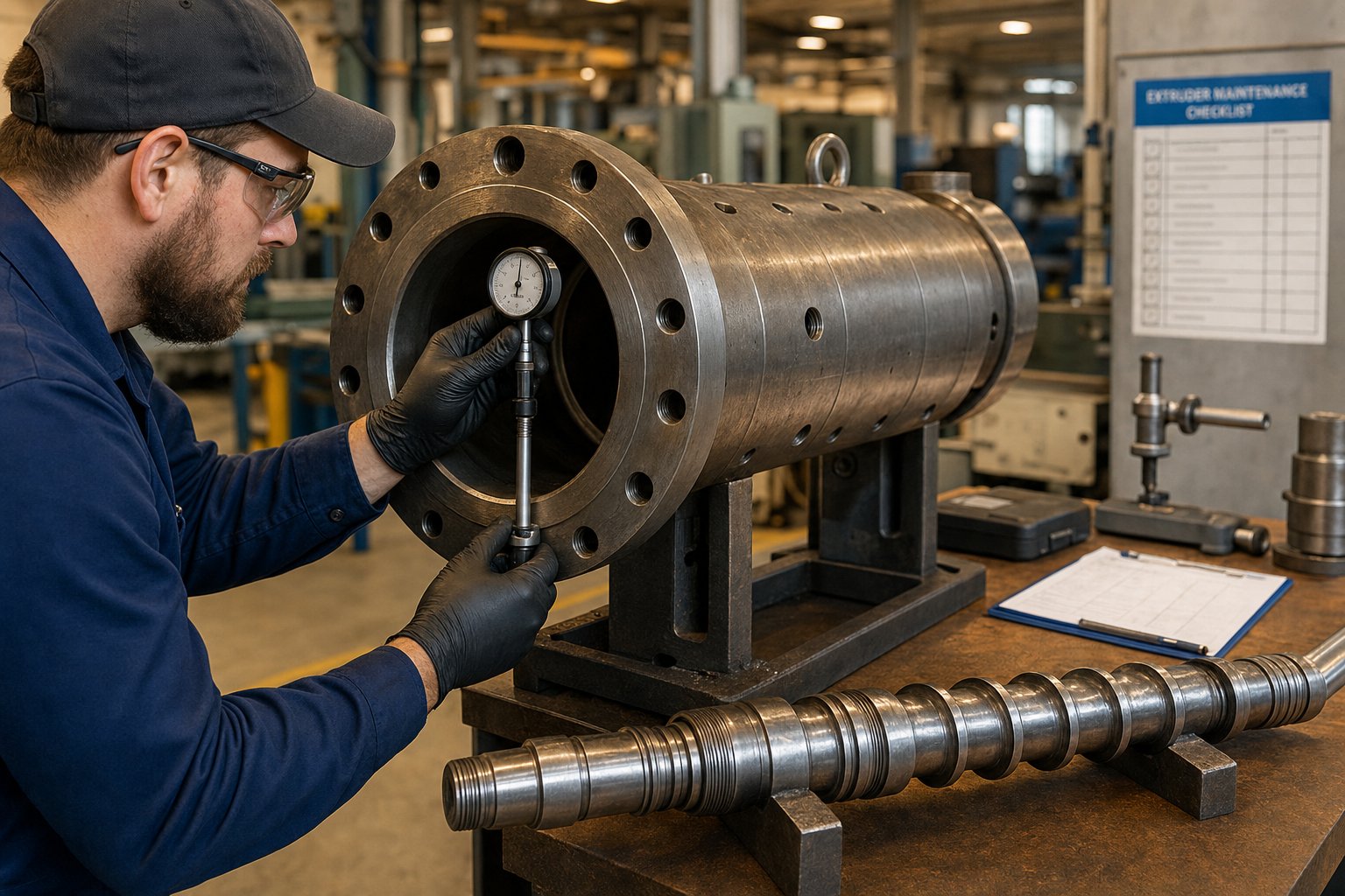
Imagine installing a new barrel-screw system and immediately recording a full set of bore diameter and screw OD measurements before any resin ever touches the metal. That's your baseline — the reference point against which every future measurement gains meaning. Without it, you're comparing today's readings to catalog specifications that may not reflect your actual as-delivered dimensions.
Measuring barrel bore is straightforward. A telescoping bore gauge or dedicated barrel bore gauge inserted from each end captures internal diameter at multiple axial positions and rotational orientations. For screws, a flight micrometer measures OD across flight tips, while root diameter readings at each zone track channel depth changes. Log every value with location, date, and cumulative run hours — not calendar time.
Why run hours instead of dates? Because a barrel that operates 6,000 hours per year wears differently than one running 2,000 hours. Graham Engineering recommends converting all calendar-based maintenance intervals to run-time intervals, installing hour meters wired into stop/start circuits on older machines. Modern PLC-equipped extruders already track this internally.
The general clearance specification provides your replacement threshold: 0.001 to 0.0015 inches per side per inch of screw diameter represents normal operating clearance. When measurements show clearance at 3-4 times original specification, output loss and melt temperature rise reach economically unsustainable levels — that's your replacement trigger, consistent with SPI Dimensional Guidelines for worn components.
When does rebuilding make sense over full replacement? If the barrel bore shows uniform wear without deep scoring, corrosion pitting, or localized damage, re-honing and re-lining with bimetallic alloy can restore it to original tolerance at 50-70% of new barrel cost. Screws with worn flight tips can be rebuilt with hard-facing weld overlays. But if bore ovality exceeds 0.1 mm or if the nitrided layer is worn through across large sections, replacement delivers better economics than attempting to save a compromised shell.
The following preventive maintenance schedule organizes extruder barrel maintenance into a run-time-based program that builds the wear data you need for predictive planning:
- Every shift (daily when running): Check barrel zone temperatures for deviation from setpoints. Listen for unusual mechanical noise. Verify motor amperage remains within historical baseline range. Inspect barrel heater bands visually for discoloration or loose clamps.
- Every 500 run hours (approximately weekly on a 24/7 line): Inspect feed throat cooling flow and temperature. Check barrel support positions against expansion marks. Verify thermocouple insertion and grounding continuity. Clean barrel fans and inspect for pellet buildup.
- Every 2,000 run hours (approximately monthly): Record motor amperage and specific output (kg/hr per RPM) at standard conditions for trend analysis. Inspect breaker plate sealing surfaces and adapter transitions. Check barrel heater band torque and contact surface condition.
- Every 4,000-6,000 run hours (quarterly to semi-annually): Pull the screw for visual inspection — check flight edges for rounding, chrome condition, straightness, and cracking. Measure screw flight OD and root diameters at all zones. Borescope the barrel bore for scoring, corrosion, or localized wear patterns.
- Every 8,000-12,000 run hours (annually): Perform full bore diameter measurement at multiple axial and rotational positions. Compare all values to baseline and previous measurements to calculate wear rate. Verify barrel alignment using optical or laser methods. Update predictive replacement timeline based on projected clearance growth.
Maintaining detailed wear records across multiple inspection cycles transforms reactive maintenance into genuine predictive capability. When you can plot clearance growth over run hours, you can extrapolate forward to predict — within a few hundred hours — when a component will cross the replacement threshold. That foresight lets you order replacement parts, schedule planned downtime during lower-demand periods, and coordinate screw and barrel changes together rather than suffering unplanned shutdowns.
For processors running multiple extrusion lines — pipe, film, sheet, pelletizing, recycling — this lifecycle tracking becomes even more valuable. Each line's wear profile differs based on polymer type, fillers, throughput rates, and operating hours. Suppliers like NANHAIYA, who provide application-specific single screw barrel configurations across pipe, film, sheet, pelletizing, and recycling lines, can cross-reference your wear data against their installed base to recommend optimal replacement intervals and surface treatment upgrades tailored to your specific processing environment. That kind of application engineering support — matching real-world wear patterns to barrel metallurgy — closes the loop between monitoring data and actionable decisions.
Of course, all of this lifecycle knowledge culminates in a practical question: when it's time to specify a new barrel and screw — whether as a replacement or for a new line — how do you pull together everything about geometry, metallurgy, tolerances, and application requirements into a confident purchasing decision?
How to Select the Right Single Screw Barrel: A Practical Selection Guide
You've got the technical knowledge — zone functions, screw geometries, surface treatments, wear mechanisms, maintenance thresholds. The challenge now is pulling all of it into a single, structured purchasing decision that you won't regret 18 months down the road. Think of this as your single screw barrel selection guide: a step-by-step framework that turns engineering understanding into a confident spec sheet.
Matching Barrel Design to Your Extrusion Application
Every selection decision follows the same logical sequence, regardless of whether you're specifying a replacement barrel for an aging pipe line or outfitting a brand-new recycling system. Work through these criteria in order — each step narrows the field and prevents expensive mismatches.
Step 1: Identify the polymer family. Is it a semi-crystalline polyolefin that needs high compression? An amorphous engineering resin with a broad softening range? A corrosive PVC or fluoropolymer? The polymer's melt behavior dictates compression ratio, temperature limits, and corrosion exposure — three variables that immediately eliminate certain barrel configurations.
Step 2: Determine throughput requirements. Your target output rate (kg/hr) sets the minimum screw diameter. Pushing a small-bore barrel beyond its natural capacity forces excessive screw speeds, generates unnecessary shear heat, and shortens component life. Size the diameter to hit your target at 60-80% of maximum RPM capacity — that leaves headroom for future rate increases without stressing the system.
Step 3: Select appropriate L/D ratio and compression ratio. Match these to both the polymer and the application. Pipe and compounding lines benefit from higher L/D (30:1+) for melt homogeneity. Film lines balance mixing needs against shear-generated heat. Refer back to the application table in the previous sections to anchor these numbers against proven configurations.
Step 4: Choose surface treatment based on wear environment. Unfilled polymers? Nitriding works. Mineral-filled or recycled feedstocks? Bimetallic with iron-boron alloy. Corrosive compounds like PVC or flame-retardant systems? Nickel-alloy corrosion-resistant liners. This single decision — which often represents only a 2-3x cost differential — can determine whether your barrel lasts one year or five.
Step 5: Verify dimensional tolerances and documentation. Request bore diameter tolerance (±0.02 mm or better), straightness certification, surface roughness specification (Ra ≤ 0.4 µm), and hardness documentation at multiple bore positions. These aren't optional quality extras — they're the measurements that confirm you're receiving what you specified.
Evaluating Suppliers and Long-Term Support
Selecting the right extruder screw and barrel supplier matters almost as much as selecting the right metallurgy. A beautifully specified barrel sourced from a supplier who can't verify their own materials is a gamble — and the stakes are measured in unplanned downtime and scrap costs. Among single screw extruder manufacturers, the spread between premium and commodity suppliers shows up not in catalog specifications (which often look identical) but in documentation quality, application engineering depth, and post-sale support.
What separates a reliable partner from a parts vendor? Evaluate against these criteria:
- Material certifications: Can the supplier provide EN 10204 3.1 certificates for base steel, liner alloy, and any hardfacing materials? If not, you have no traceability on what's actually inside your barrel.
- Dimensional inspection reports: CMM-generated bore measurements at multiple axial positions, confirming roundness, straightness, and diameter within specified tolerance. Not a single spot-check — a full profile.
- Metallurgical testing: Hardness maps at multiple bore locations, and for bimetallic barrels, cross-section metallography confirming liner thickness, bond integrity, and absence of porosity.
- Application engineering support: Can their technical team recommend screw geometry, compression ratio, and surface treatment based on your specific polymer, filler loading, and production goals? Or do they just fill orders from your drawing?
- Broad application coverage: Suppliers serving multiple extrusion segments — pipe, film, sheet, pelletizing, recycling — accumulate cross-application knowledge that pure commodity suppliers lack. For example, NANHAIYA provides application-specific single screw barrel configurations across pipe, film, sheet, pelletizing, recycling, and general-purpose extrusion lines — the kind of breadth that lets a supplier draw on thousands of installed configurations when recommending yours.
- Lead times and inventory strategy: For critical production lines, a supplier with standard-diameter barrels in stock or with short lead times prevents extended downtime when unplanned replacement becomes necessary.
- Rebuild and refurbishment capability: Suppliers who offer barrel re-lining and screw hard-facing extend component life at 40-60% of new-part cost, giving you a complete lifecycle partner rather than just a new-parts vendor.
Here's the uncomfortable truth about procurement decisions in this category: the screw and barrel together represent under 5% of a typical extruder's capital cost — yet they govern 60% to 75% of its lifetime operating economics through wear-driven downtime, energy consumption, and melt quality. Optimizing for the lowest purchase price almost always produces the highest total cost of ownership. A barrel that costs 30% more but lasts three times longer in your specific application isn't an expense — it's the cheapest option you have.
Calculate total cost of ownership over a realistic 36-month production horizon: initial purchase plus replacement frequency multiplied by changeover labor, plus downtime cost per event, plus energy penalty from increasing clearance over service life. That number — not the line item on a purchase order — is what your barrel selection actually costs.
The processors who get this right share a common approach: they treat barrel and screw selection as an engineering decision first and a purchasing decision second. They match metallurgy to their wear environment, verify documentation before accepting delivery, and track wear rates to predict replacement timing rather than waiting for quality failures to force their hand. Everything in this article — from zone mechanics to surface treatments to maintenance schedules — feeds into that single discipline of making informed, data-driven choices about the component that quietly determines whether your extrusion line runs profitably or just runs.
Frequently Asked Questions About Single Screw Barrels
1. What is the difference between a nitrided barrel and a bimetallic barrel?
A nitrided barrel uses gas nitriding to harden the bore surface to approximately 950-1,050 HV, but the wear-resistant layer is only 0.4-0.7 mm deep. A bimetallic barrel features a centrifugal-cast alloy liner 1.6-3.0 mm thick bonded inside a steel shell, providing three to six times the wear reserve. Nitrided barrels suit clean, unfilled polymers at lower cost, while bimetallic options are recommended for abrasive fillers, recycled feedstocks, or corrosive compounds like PVC and flame-retardant systems. Over a typical service cycle, a bimetallic barrel may outlast three to four nitrided replacements, often delivering lower total cost of ownership despite a higher upfront price.
2. How do I know when my single screw barrel needs replacement?
The most reliable indicator is screw-to-barrel clearance growth measured with bore gauges and flight micrometers. Industry guidelines suggest replacement when clearance reaches approximately three to four times the original specification. Symptoms that signal approaching this threshold include declining specific output (kg/hr per RPM), rising discharge melt temperature at unchanged screw speeds, output surging, and visible melt-quality defects like unmelted particles or gels. Establishing baseline bore and screw measurements at installation and tracking them at regular run-hour intervals lets you predict replacement timing and schedule downtime proactively rather than reacting to quality failures.
3. What L/D ratio should I choose for my single screw extruder?
The ideal L/D ratio depends on your polymer and application. Standard polyolefins like HDPE and PP plasticize effectively at 20:1 to 25:1. Engineering plastics, ABS, and PVC profiles that require better mixing typically need 28:1 to 30:1. Compounding, masterbatch production, vented degassing, and recycling applications push the ratio to 32:1 or even 36:1 to accommodate additional mixing elements or two-stage decompression zones. Higher L/D ratios improve melt homogeneity and mixing but increase shear energy input, machine footprint, and cost, so the selection should balance processing quality against practical constraints.
4. Why does my extruder produce black specks and how is the barrel involved?
Black specks typically originate from carbonized polymer trapped in dead spots within the barrel, adapter transitions, or damaged bore surfaces. When polymer stagnates in areas of poor flow - such as oversized screw-to-barrel gaps, scoring on the bore, or poorly designed transition fittings - it degrades and carbonizes over time, periodically releasing dark particles into the melt stream. The telltale sign is specks that worsen with runtime and especially after startups. Corrective action involves pulling the screw, inspecting the bore with a borescope for surface damage or corrosion pitting, and checking all adapter and die transitions for stagnation zones. Suppliers like NANHAIYA can recommend application-matched barrel configurations at nhyscrews.com that minimize hang-up points for cleaner melt output.
5. What types of screw designs are available for single screw extruders?
The main screw geometries include conventional three-zone metering screws, barrier screws, vented two-stage screws, and grooved-feed designs. Barrier screws use a secondary flight to separate solids from melt, preventing unmelted particles from reaching the die - ideal for high-output film and pipe lines. Vented screws feature a decompression zone with a barrel vent port that removes moisture and volatiles during processing, suited for recycling and hygroscopic polymers like PET and nylon. Grooved-feed sections mechanically grip pellets to stabilize throughput independent of friction, benefiting slippery polyolefins. Additionally, mixing elements such as Maddock dispersive mixers, pin mixers, and pineapple elements can be added to improve additive and colorant distribution within the melt.
Written by
Nanhaiya Technical Team
Zhoushan Nanhaiya Plastic Machinery Co., Ltd.
The Nanhaiya technical team supports screw and barrel manufacturing projects through application review, technical communication, custom manufacturing coordination, and production and quality control.
Discuss Your Application
Related Articles
More insights on screw barrel technology and plastics processing.

What Nobody Tells You About Screw Barrel For Plastic Machine Design
Oct 10, 2026
Learn how screw barrel for plastic machine design affects melt quality, throughput, and wear life. Covers geometry, resin matching, troubleshooting, and sourcing.
Read Article
Single Screw Extruder for Sheet: Stop Guessing, Start Specifying
Oct 9, 2026
Learn how to specify a single screw extruder for sheet production. Covers screw geometry, resin-specific processing, troubleshooting, and maintenance best practices.
Read Article
PE Pipe Extruder Machine: What Datasheets Won't Tell You
Oct 9, 2026
Learn how a PE pipe extruder machine works, key specs explained, material grade selection, maintenance tips, and buyer guidance beyond the datasheet.
Read ArticleLooking for something else?
Search by material, symptom or product and jump straight to the relevant page.
These are navigation suggestions based on keyword matching — not a quotation, not a delivery commitment, and not a substitute for engineering review. Final specification is confirmed by our engineers against your drawings and processed material.
Need help with screw barrel selection?
Share your machine model, processed material and application. Our team can help with pricing and technical support.