

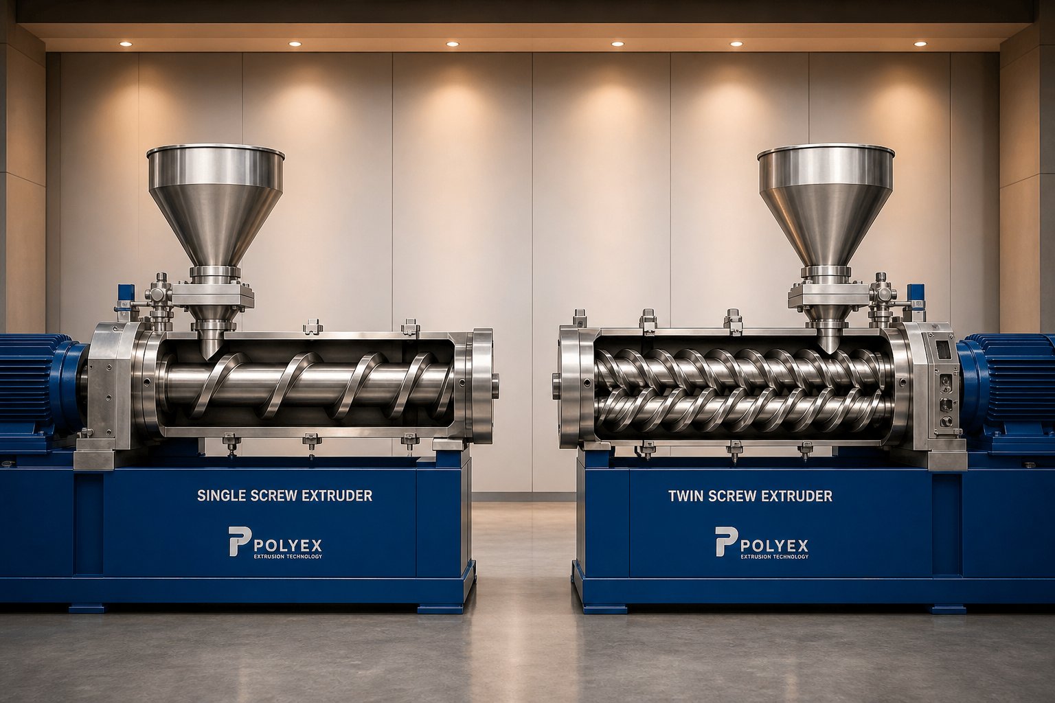
How Screw Extruders Work and Why the Distinction Matters
Every plastics processing line starts with one decision that echoes through decades of production: which screw extruder sits at the heart of the operation? Choose well, and you get reliable throughput, consistent melt quality, and manageable operating costs. Choose poorly, and you inherit years of compromised output, excessive maintenance, and frustrated operators.
What Is a Screw Extruder
A screw extruder is a polymer processing machine that melts, mixes, and shapes materials by forcing them through a die using one or more rotating screws inside a heated barrel.
That core principle has remained remarkably stable since the earliest single screw extruder designs emerged in the mid-20th century as simple melt pumps for thermoplastics. Those early machines excelled at pushing pre-compounded pellets through a die to form pipes, sheets, and films. As formulations grew more complex, demanding intensive mixing of fillers, additives, and polymer blends, engineers turned to twin screw extruder technology. Co-rotating intermeshing designs, in particular, introduced modular screw elements, self-wiping geometry, and precise residence time control that a single-screw machine simply could not match.
This article delivers a vendor-neutral, engineer-to-engineer comparison of both platforms. No promotional bias, no brand rankings. Just the technical facts you need to match the right screw extruder to your material, your process, and your budget.
Key Extrusion Terms Every Engineer Should Know
Before diving into machine-specific details, here is a quick-reference glossary of terms you will encounter throughout this guide:
- L/D Ratio - The length-to-diameter ratio of the screw. A higher L/D (e.g., 40:1 vs. 24:1) provides more processing length for melting, mixing, and devolatilization.
- Specific Energy (SE) - The motor power consumed per kilogram of material processed (kW per kg/hr). It quantifies how much mechanical energy a formulation actually requires and is essential for troubleshooting and scale-up.
- Dispersive Mixing - The breaking down of agglomerates or droplets into smaller particles using high shear stress, critical when incorporating pigments or nanofillers.
- Distributive Mixing - The spatial redistribution of components throughout the melt to achieve compositional uniformity, without necessarily applying high shear.
- Die Swell - The expansion of the extrudate diameter beyond the die opening, caused by the elastic recovery of the polymer melt after exiting the die.
- Melt Fracture - A surface distortion of the extrudate that occurs when wall shear stress at the die exceeds a critical threshold, resulting in sharkskin, orange peel, or gross irregularities.
With these fundamentals in place, the real question becomes structural: what happens inside a single-screw barrel versus a twin-screw barrel, and how do those mechanical differences translate into processing capability?
Single Screw Extruder Design and Performance Fundamentals
Imagine a single helical flight wrapped around a cylindrical root, spinning inside a heated barrel. That deceptively simple geometry is what makes every plastic single screw extruder tick. The screw does not push material forward the way a piston would. Instead, it relies on drag flow: the polymer adheres to the stationary barrel wall while the rotating screw generates a relative velocity that drags the melt downstream. Essentially, from a force-balance perspective, the barrel acts as the moving surface and the polymer in contact with it provides the transport mechanism.
This drag-flow principle governs everything a single screw extrusion machine can and cannot do. Understanding the zones where it operates is the first step toward knowing whether this platform fits your process.
Anatomy of a Single Screw Extruder
A standard single extruder screw divides its working length into three geometrically distinct zones, each created by varying the channel depth while keeping the flight pitch constant:
- Feed Zone - The deepest channel section, located directly beneath the hopper. Here, solid pellets or granules enter the annular space between screw and barrel. The deep flights maximize volumetric intake and begin conveying the material forward through frictional drag. Water-cooled feed throats prevent premature melting that would restrict the flow of incoming solids.
- Compression (Transition) Zone - Channel depth decreases progressively in this section, compressing the solid bed against the barrel wall. Frictional heat from the screw-polymer-barrel interaction, combined with conducted heat from barrel heaters, initiates melting. The compaction squeezes air out of the feed and increases the density of the material, transitioning it from a loosely packed solid to a partially molten mass.
- Metering Zone - The shallowest channel section, where depth remains constant. By this point, the polymer should be fully molten and thermally homogeneous. The metering zone functions as a melt pump, generating the pressure required to push material through the screen pack and die at a consistent volumetric rate.
The ratio of these zone lengths, along with the maximum and minimum channel depths, defines the screw's compression ratio. Different polymers demand different compression ratios. A low-density polyethylene might use a 3:1 ratio, while a rigid PVC compound could require something closer to 2:1 to avoid overheating a shear-sensitive resin.
L/D ratios for a typical single screw extruder machine range from 24:1 to 36:1. A longer L/D provides more residence time for melting and thermal homogenization, which is why modern high-output lines often favor 30:1 or 32:1 screws. Barrel diameter directly scales throughput capacity: doubling the diameter roughly quadruples the annular channel area, though the exact output increase also depends on screw speed, back pressure, and polymer rheology.
Strengths and Limitations of Single Screw Systems
Single screw extrusion has dominated the plastics industry for decades, and for good reason. When the job is steady-state pumping of a pre-compounded material through a shaping die, few machines do it more cost-effectively.
Core Strengths
- Lower capital cost - Simpler drive train, single barrel bore, and fewer precision components reduce the initial investment significantly compared to twin screw platforms.
- Excellent pressure generation - The drag-flow mechanism builds substantial die-head pressure, making single screw machines ideal for feeding restrictive dies used in pipe, profile, sheet, and blown film extrusion.
- Simpler operation - Fewer process variables to control translates into shorter operator training cycles and more predictable day-to-day performance.
- Lower maintenance complexity - One screw, one barrel bore, and no intermeshing geometry to align. Replacement part inventories stay lean.
Key Limitations
- Limited mixing capability - Because polymer tends to stay in the same radial position within the channel, full turnover of the melt is difficult. Shear rate peaks at the barrel surface and drops to near zero at the screw root, creating velocity stratification that resists complete blending.
- Narrow feed flexibility - Most single screw machines are designed to accept free-flowing pellets. Powders with poor flowability can bridge in the hopper, and liquids generally require specialized injection systems downstream.
- Poor self-cleaning properties - Material can stagnate in the screw channel, particularly at low-flow areas near flight roots. Changeovers between colors or materials take longer and generate more scrap.
- Broader residence time distribution - Drag-flow mechanics and potential dead zones mean that some polymer spends significantly more time in the barrel than the rest, a concern for heat-sensitive resins.
Enhanced Mixing Sections for Single Screw Machines
Engineers have never simply accepted the mixing limitations of single screw systems. Over the decades, several screw modifications have been developed to bridge the gap, at least partially.
Barrier screws introduced a secondary flight that separates the solid bed from the melt pool within the transition zone. This forces melting to complete more uniformly and predictably, eliminating unmelted particles that would otherwise reach the die. Once material passes through a properly designed barrier section, it should be completely molten.
Maddock-type mixers (also known as Leroy or UCC mixers) remain one of the most widely used dispersive mixing elements. The design forces the entire melt to pass over a narrow clearance barrier between inlet and outlet flutes, providing full channel turnover combined with a brief burst of high shear. Jim Frankland of Frankland Plastics Consulting notes that the Maddock concept was deliberately modeled on twin-screw mixing principles: complete polymer turnover plus controlled high shear. However, its inherent pressure drop limits practical use to mostly a single section, because repeating it aggressively would reduce output and spike melt temperature.
Distributive mixers such as pin mixers, Saxton-type elements, and pineapple mixers take a different approach. Rather than applying high shear, they divide the melt stream into many sub-streams and recombine them repeatedly, creating exponential layering that improves thermal and compositional uniformity. For barrier screws that already complete melting in the barrier section, distributive mixers are generally the better downstream choice because they homogenize temperature and color without needlessly elevating melt temperature.
These enhancements meaningfully improve a plastic single screw extruder's performance for applications like color blending or thermal homogenization. Yet they cannot replicate the full-channel, screw-to-screw polymer transfer that twin screw machines achieve through intermeshing geometry. That fundamental mechanical difference is what opens the door to entirely different extruder configurations, each built around two screws working in concert rather than one.
Twin Screw Extruder Types and Configuration Taxonomy
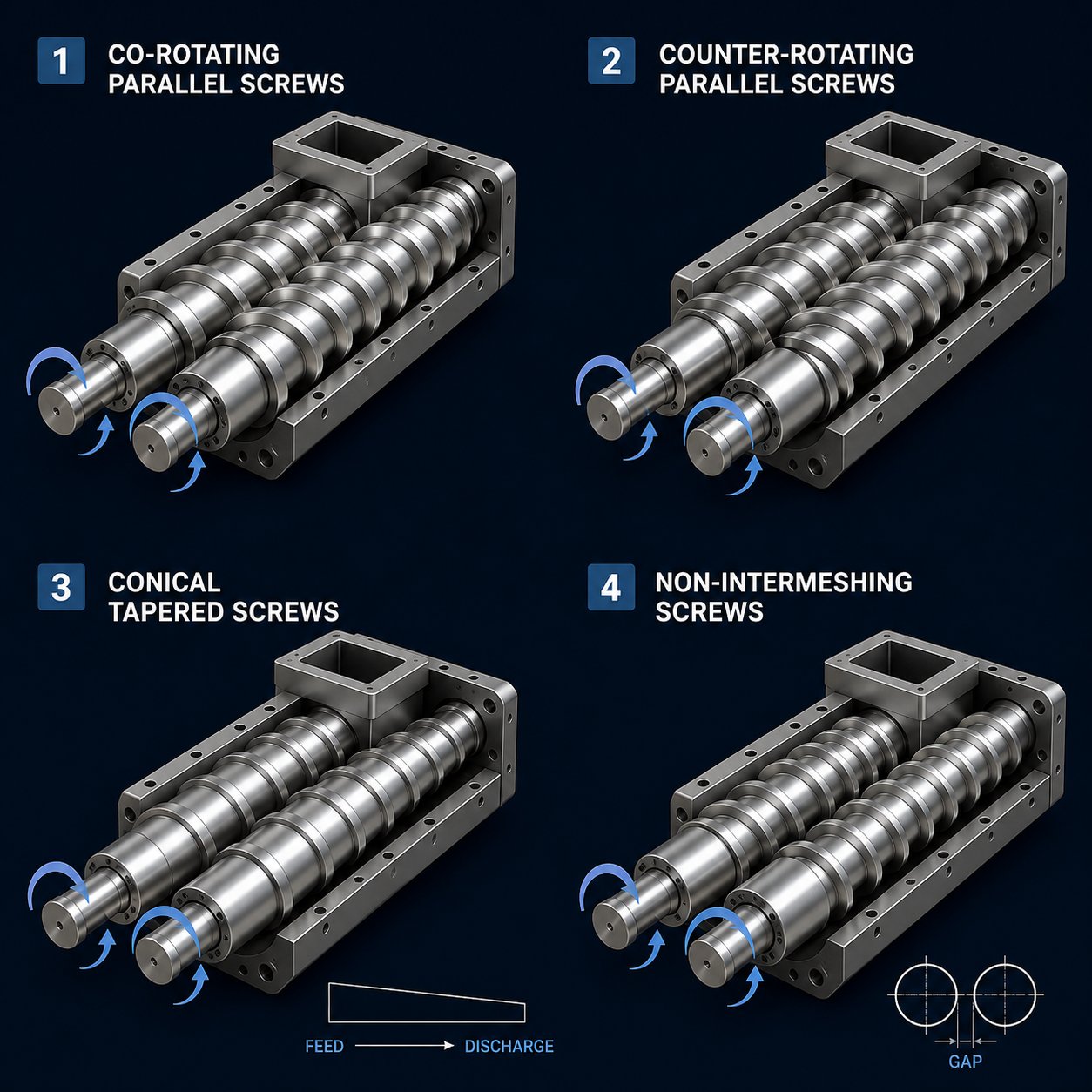
Two screws working in concert sounds straightforward, but the way those twin screws interact with each other, the direction they rotate, and the geometry of their shafts create fundamentally different processing environments. Selecting between these configurations is not a preference; it is an engineering decision that determines mixing intensity, residence time control, and the range of materials a line can handle. Here is the full taxonomy every processing engineer should understand.
Co-Rotating Twin Screw Extruders
In a co-rotating twin screw extruder, both screws spin in the same direction. Picture the melt path from above: material follows a figure-eight or infinity-shaped ("∞") trajectory, transferring from one screw channel to the other at each intermeshing zone. This constant screw-to-screw handoff is what gives co-rotating designs their standout characteristics: outstanding dispersive and distributive mixing, excellent self-cleaning behavior, and remarkable process flexibility.
Because the screws wipe each other's surfaces with every rotation, very little material stagnates inside the barrel. That self-wiping action keeps residence time distribution narrow and changeover times short. You'll find co-rotating configurations dominating applications where mixing complexity is high: polymer compounding with fillers and additives, reactive extrusion requiring controlled reaction time, devolatilization of solvents or moisture, and pharmaceutical hot-melt extrusion where content uniformity is non-negotiable.
Most co-rotating platforms use a parallel twin screw extruder layout, meaning the screw diameter stays constant along the full barrel length. This allows engineers to build modular screw profiles by stacking interchangeable elements, conveying segments, kneading blocks, and mixing discs, on a splined shaft. That modularity is a defining advantage discussed in detail later in this article.
Counter-Rotating Twin Screw Extruders
When the two screws turn in opposite directions, the material behavior changes dramatically. Instead of a figure-eight transfer, the melt experiences a calendering action in the nip region between the screws. Imagine two rollers pulling material into the gap between them: that converging zone generates localized high shear and strong positive conveying forces.
Understanding co rotating and counter rotating twin screw extruder differences helps clarify why each suits particular jobs. Counter-rotating designs excel where controlled, positive displacement conveying matters more than intensive mixing. PVC processing is the classic example. Rigid PVC is notoriously heat-sensitive, so the lower overall shear and gentle plasticizing behavior of counter-rotating screws prevent degradation while still delivering the pressure needed for profile and pipe dies. Cable coatings, rigid sheet production, and certain specialty compounding tasks also benefit from this configuration.
Intermeshing vs Non-Intermeshing Configurations
Screw rotation direction is only half the story. The degree to which the twin screws physically engage each other creates another critical axis of classification.
- Intermeshing - The flight of one screw extends into the channel of the other. This tight engagement provides positive conveying, meaning material is physically pushed forward rather than relying purely on drag flow. Self-wiping geometry keeps surfaces clean and residence time distribution narrow, which is essential for heat-sensitive or reactive formulations. The vast majority of modern compounding extruders use fully intermeshing designs.
- Non-intermeshing - The screws rotate side by side without direct flight-to-flight contact. Each screw essentially behaves more like an independent single screw operating within a shared barrel. Shear forces are lower, residence time distribution is wider, and the screws do not self-clean. However, this gentler environment suits devolatilization tasks and reactive extrusion scenarios where precise temperature control and extended dwell time matter more than aggressive mixing.
Think of it this way: intermeshing screws actively hand material back and forth, while non-intermeshing screws let material exchange happen more passively through open channels between them.
Conical Twin Screw Extruders
Not all twin screws run parallel. A conical twin screw extruder uses tapered screws that are larger at the feed end and progressively narrow toward the discharge. This geometry solves an elegant engineering problem: the wide feed section provides a large root diameter and high torque capacity right where bulk material enters, while the smaller discharge end creates a natural compression zone that builds pressure gently.
Conical designs are most commonly counter-rotating and intermeshing. You'll see them widely deployed in PVC window profile extrusion lines, rigid PVC pipe production, and medium-capacity applications where compact machine footprint is valued. The tapered screw geometry also delivers high torque transmission relative to machine size, making conical extruders well-suited for processing high-viscosity or bulky feed materials without the oversized gearbox a parallel machine might require. Many laboratory and micro-compounding systems also adopt conical configurations because the design accommodates small batch sizes efficiently.
Configuration Comparison at a Glance
| Configuration | Primary Conveying Mechanism | Mixing Type | Self-Cleaning Ability | Best-Fit Applications |
|---|---|---|---|---|
| Co-Rotating Intermeshing (Parallel) | Figure-eight screw-to-screw transfer | Excellent dispersive and distributive | High (self-wiping geometry) | Polymer compounding, reactive extrusion, devolatilization, pharmaceutical HME |
| Counter-Rotating Intermeshing (Parallel) | Calendering action at nip region | Moderate; lower shear than co-rotating | Moderate | PVC profiles and pipe, rigid sheet, cable coatings |
| Conical Twin Screw (Typically Counter-Rotating) | Tapered compression with positive displacement | Moderate; gentle shear profile | Moderate | PVC window profiles, rigid pipe, medium-capacity lines, lab-scale compounding |
| Non-Intermeshing (Co- or Counter-Rotating) | Friction-based, similar to two parallel single screws | Low to moderate; minimal dispersive | Low (no self-wiping) | Devolatilization, reactive extrusion, gentle handling of heat-sensitive materials |
Each of these configurations defines the macro-level behavior of the extruder, how material moves, how aggressively it gets mixed, and how easily the barrel cleans out between runs. But the real performance tuning happens at a finer scale: the individual screw elements mounted along that shaft. Their geometry, sequencing, and offset angles are what transform a general-purpose machine into a precision processing tool for a specific formulation.
Single Screw vs Twin Screw Extruder Side-by-Side Comparison
Knowing the configurations is one thing. Knowing which parameters actually separate these platforms in day-to-day production is what drives the right purchase order. When you line up a single screw machine against a twin-screw extruder across every performance axis that matters, the strengths and trade-offs become impossible to ignore. The table below distills over a dozen critical parameters into a single reference you can pull up during your next specification review or capital expenditure meeting.
Comprehensive Parameter Comparison Table
| Parameter | Single Screw Extruder | Twin Screw Extruder (Co-Rotating Intermeshing) |
|---|---|---|
| Dispersive Mixing | Limited; requires add-on mixing sections (Maddock, barrier flights) | Excellent; kneading blocks deliver high-shear breakdown of agglomerates |
| Distributive Mixing | Moderate with pin or pineapple mixers; poor without them | Excellent; figure-eight flow creates continuous melt turnover |
| Throughput Capacity | High for single-material pumping; scales well with barrel diameter | High for compounding; throughput tied to screw speed and fill level |
| Shear Rate Control | Limited; shear is geometry-dependent and largely fixed | Highly adjustable via modular screw element selection and sequencing |
| Residence Time Distribution (RTD) | Broad; drag flow and dead zones create wide variation | Narrow; positive conveying and self-wiping minimize stagnation |
| Self-Cleaning Ability | Poor; material retention in channels extends changeover times | Excellent; intermeshing self-wiping geometry keeps surfaces clean |
| Feed Flexibility | Primarily pellets; powders and liquids require special adaptations | Pellets, powders, fibers, liquids, and slurries via side feeders and injection ports |
| Venting / Devolatilization | Basic; limited to one or two vent ports with modest efficiency | Strong; multiple vent zones with vacuum capability for deep devolatilization |
| Capital Cost | Lower; simpler drive, single bore barrel, fewer precision parts | Higher; complex gearbox, dual-bore barrel, modular screw inventory |
| Maintenance Complexity | Low; one screw, one barrel bore, straightforward alignment | Moderate to high; intermeshing clearances, element wear, gearbox service |
| Energy Consumption per kg | Generally lower for simple melting and conveying tasks | Higher mechanical input, but lower net energy per kg of qualified product in complex compounding |
| Material Versatility | Best with pre-compounded, homogeneous resins | Handles filled, reinforced, reactive, and multi-component formulations |
| Process Control Precision | Moderate; fewer independent variables to manipulate | High; screw speed, feed rate, barrel zones, and screw profile all independently adjustable |
| Scalability | Well-established scale-up rules based on drag-flow theory | Scale-up follows specific energy and fill-level models; lab-to-production paths well documented |
| Typical L/D Ratios | 24:1 to 36:1 | 32:1 to 52:1 (co-rotating); shorter for counter-rotating and conical |
A quick scan of the table reveals that twin screw extrusion dominates nearly every performance metric tied to mixing, flexibility, and process control. So why doesn't every plant simply install a double screw extruder machine and move on? Cost and complexity. For steady-state pumping of a pre-compounded polyolefin into a sheet die, a single screw platform delivers the same output at lower capital expenditure, lower energy draw, and with operators who need far less specialized training. The comparison is never about which machine is universally better; it is about which parameters your specific process actually demands.
Three differentiators tend to tip the decision more than any others. First, mixing capability is the most obvious fork in the road. If your formulation involves dispersing carbon black agglomerates, blending incompatible polymer phases, or uniformly distributing glass fibers, the screw-to-screw material transfer in a twin screw system is not optional; it is essential. Second, feed flexibility matters enormously for operations that handle powders, recycled flake with variable bulk density, or liquid additives injected downstream. Single screw designs struggle with anything that does not flow freely into the feed throat. Third, and perhaps least appreciated, is residence time distribution.
Why Residence Time Distribution Is a Critical Differentiator
Residence time distribution, or RTD, describes how uniformly individual material particles spend time inside the extruder barrel. Imagine dropping a dye pulse into the feed: in a narrow RTD system, almost all the dye exits within a tight time window. In a broad RTD system, some dye exits quickly while the rest trickles out over an extended period, meaning portions of your polymer sat in the barrel far longer than the average.
Why does this matter? For heat-sensitive materials like PVC or bioplastics, the fraction of material that lingers too long can degrade, discolor, or generate black specks that contaminate your product stream. In reactive extrusion, where a chemical reaction must proceed to a specific conversion level, a wide RTD means some material over-reacts while other material under-reacts, destroying batch-to-batch consistency. Even in standard screw extrusion of filled compounds, broad RTD causes thermal history variation that shows up as inconsistent mechanical properties in the finished part.
A twin-screw extruder with intermeshing, self-wiping geometry inherently delivers narrow RTD because positive conveying eliminates dead zones. Material moves forward in well-defined axial segments rather than recirculating unpredictably in drag-flow channels. Single screw machines, by contrast, have broader RTD because the drag-flow mechanism allows material near the screw root to travel more slowly than material near the barrel wall, creating velocity gradients that widen the distribution.
This single parameter, how tightly you can control the time every gram of material spends inside your barrel, often becomes the deciding factor for engineers processing anything beyond straightforward, thermally robust polyolefins. Yet controlling residence time is only half the equation. The other half is controlling what happens to the material during that time, and that comes down to screw element geometry: the kneading blocks, mixing discs, and reverse elements that define the processing intensity at every point along the barrel.

Screw Element Design and Modular Configuration Strategies
Here is where the twin screw extrusion process separates itself from every other polymer processing platform: the screw is not a single machined part. It is a carefully sequenced assembly of individual elements, each shaped to perform a specific job, all threaded onto a common splined shaft. Swap one element, change an offset angle, add a reverse segment, and the extruder behaves like an entirely different machine. That modularity is the reason a single twin screw compounding extruder can run a gentle color masterbatch in the morning and an aggressively devolatilized engineering resin in the afternoon.
Understanding each element category, what it does to the melt, where it belongs on the shaft, and how it interacts with neighboring elements, is essential for any engineer who wants to move beyond default screw profiles and start designing for specific formulations.
Twin Screw Modular Elements Explained
Every modular screw profile is built from four fundamental element families. Think of them as the vocabulary of screw design: each word means something specific, and the sentence you construct from them determines the story your extruder tells.
- Conveying Elements - These are the workhorses of material transport. They look like standard helical screw flights with a defined pitch and channel depth. Their job is straightforward: grip incoming pellets or powder and push them forward along the twin screw barrel with minimal shear input. Larger pitch moves material faster and keeps fill levels low, which is ideal in feed zones and around vent ports where you want pressure relief. Smaller pitch slows transport, increases compression, and builds the pressure needed to push melt through a die. Conveying elements strongly affect fill level in each section of the extruder, which in turn controls how downstream kneading blocks and mixing elements interact with the material.
- Kneading Blocks - Stacks of lobe-shaped discs mounted on the shaft at specific angular offsets. Each disc forces the melt through narrow gaps and rapidly changing cross-sections, splitting, folding, and recombining the flow. The stagger angle between adjacent discs is the primary lever for tuning mixing intensity. Kneading blocks are the most powerful mixing tools available in the twin screw and barrel assembly, and they deserve their own detailed discussion below.
- Mixing Elements (Toothed / Gear-Type) - These elements feature rows of teeth or gear-like lobes that divide the melt stream into many small sub-streams and recombine them repeatedly. They excel at distributive blending, spreading additives, colorants, or minor-phase polymers evenly through the matrix without imposing the high shear stress of an aggressive kneading block. Toothed mixing elements can perform both distributive and dispersive mixing, though their dispersive contribution is modest compared to dedicated kneading blocks.
- Reverse Elements - Left-handed pitch screw segments that actively push material backward against the main flow direction. The overall extruder still moves material forward, but the local backflow creates a dam effect: pressure builds upstream, fill level increases, and residence time extends in the preceding zone. Reverse elements are essential for creating melt seals ahead of vacuum vent ports, increasing the intensity of upstream kneading zones, and ensuring complete melting before material enters a mixing section.
Kneading Block Geometry and Its Impact on Mixing
Kneading blocks are where the real performance tuning happens, and three variables control nearly everything about their behavior: disc width, the number of discs in the block, and the stagger angle between adjacent discs.
Stagger angle is the most influential parameter. Imagine looking down the shaft and watching how each disc is rotated relative to the one before it:
- 30-degree offset (low stagger) - Promotes forward conveying with moderate shear. Material passes through relatively gently, making this configuration ideal for distributive mixing where you want uniform blending without excessive temperature rise. Think color concentrates or heat-sensitive biopolymer blends.
- 60-degree offset (medium stagger) - Balances forward pumping with meaningful shear intensity. This is the general-purpose workhorse configuration for many compounding applications, delivering both reasonable dispersive and distributive mixing.
- 90-degree offset (neutral stagger) - Provides nearly zero net forward conveying. Material essentially oscillates back and forth across the block, dramatically increasing local residence time, back-mixing, and shear exposure. This configuration delivers strong dispersive mixing for deagglomeration but also raises melt temperature and torque significantly. Use it deliberately, not by default.
Beyond stagger angle, disc width plays a complementary role. Narrower discs create more frequent changes in the cross-sectional flow pattern along the screw axis, generating higher local pressure fluctuations and more opportunities for extensional flow. The result is stronger dispersive action per unit length. Wider discs produce smoother, gentler flow paths and favor distributive mixing. Block length, the total number of discs in sequence, controls cumulative energy input: longer blocks provide more repeated splitting and recombining cycles but also contribute more viscous heating.
Forward kneading blocks push material downstream while mixing. Reverse kneading blocks push material backward, creating intense pressure buildup and maximum shear upstream, perfect for tough deagglomeration tasks or creating a melt seal. Neutral blocks sit in between, maximizing local residence time without strong directional bias.
The design challenge, as any experienced compounder will tell you, is delivering just enough shear and residence time to achieve target dispersion without over-working the material. More kneading blocks and higher stagger angles increase shear and mixing but also raise melt temperature and torque, which can push heat-sensitive formulations into degradation territory or trip the drive's overload protection.
Screw Element Quick-Reference Map
| Element Type | Primary Function | Typical Position on Screw | Resulting Process Effect |
|---|---|---|---|
| Conveying Element (Large Pitch) | Rapid material transport with low compression | Feed zone; around vent ports | High throughput, low fill level, minimal shear; enables gas escape at vents |
| Conveying Element (Small Pitch) | Pressure buildup and controlled compression | Metering zone near die; pre-mixing zone | Increased pressure for die feeding; higher fill level for downstream elements |
| Kneading Block (30-degree Forward) | Gentle distributive mixing with forward conveying | First mixing zone after initial melt | Uniform blending of additives; low temperature rise |
| Kneading Block (60-degree Forward) | Balanced dispersive and distributive mixing | Primary mixing zone | Moderate agglomerate breakup; good color development |
| Kneading Block (90-degree Neutral) | Intensive dispersive mixing with high back-mixing | High-shear zone for stubborn agglomerates | Strong deagglomeration; significant melt temperature increase |
| Reverse Kneading Block | Maximum restriction and dispersive intensity | Upstream of vent zones; after side feeders | Melt seal creation; pressure buildup; extended residence time |
| Toothed / Gear Mixing Element | Distributive blending with minimal dispersive shear | Final homogenization zone before die | Even spatial distribution of minor components; low added temperature |
| Reverse Conveying Element | Backflow restriction and pressure dam | Ahead of vacuum vent ports; end of melting zone | Increased upstream fill; melt seal for devolatilization; extended dwell time |
Single Screw Design Customization Options
Contrast all of this with the single screw platform. A conventional single screw is a one-piece machined component: feed zone, compression zone, and metering zone are carved into a continuous steel shaft. You cannot pull off a kneading block, swap a stagger angle, or insert a reverse element before your next production run.
That said, single screw design is not entirely static. Engineers have several customization levers:
- Barrier flights - A secondary flight separates the solid bed from the melt pool in the compression zone. This accelerates melting and eliminates unmelted particles downstream, but the geometry is permanently machined.
- Mixing pins - Metal pins protruding from the screw root disrupt the helical flow pattern and force some cross-channel movement. They provide modest distributive mixing without the complexity of a modular system.
- Maddock-type dispersive sections - Machined fluted sections force the entire melt to pass over a clearance barrier, providing a controlled burst of high shear. Effective but limited to one, or at most two, sections per screw to avoid excessive pressure drop.
- Variable-pitch or variable-depth profiles - Changing the pitch or channel depth along specific zones lets designers tailor compression ratio and melting behavior to a specific polymer family. However, once machined, the profile serves that material range and no other.
The fundamental difference is permanence versus flexibility. A single screw gives you one processing profile per physical screw. To change behavior meaningfully, you pull the screw and install a different one, a multi-hour job that shuts down the line. A twin screw compounding extruder lets you rearrange elements on the shaft, often within an hour, and dial in a completely new processing profile without replacing the shaft itself.
This modularity is precisely why twin screw platforms dominate applications where formulations change frequently, where new products demand rapid process development, or where a single extruder must serve multiple product families. It is also why screw element design is considered both an art and a science: no gold standard profile exists for all materials, because every formulation exhibits unique flow properties that respond differently to temperature, shear rate, and extruder geometry.
Knowing how to arrange these elements is essential, but knowing which element combinations suit which materials and industries turns screw design theory into production reality. The next logical step is mapping specific polymer families and industry sectors to the extruder platform, and the screw configuration, best suited to handle them.
Matching Materials and Industries to the Right Extruder
Screw element theory only matters when it connects to real materials running on real production floors. The question engineers face daily is blunt: given this polymer, this filler package, and this end-use requirement, which extruder platform actually delivers? Generic advice like "twin screws are better for mixing" does not cut it when you are specifying a capital purchase for a specific product line. What you need is a material-by-material and industry-by-industry map that ties processing demands to machine architecture.
Material Family to Extruder Type Mapping
Different polymer families impose fundamentally different demands on the extruder. A crystalline engineering resin loaded with 30% glass fiber behaves nothing like a neat polyethylene destined for blown film. The table below pairs each major material family with the extruder configuration best suited to handle it, along with the processing rationale behind each recommendation.
| Material Family | Recommended Extruder Type | Rationale |
|---|---|---|
| Polyolefins (PE, PP) for film, sheet, pipe | Single screw | Pre-compounded pellets need steady-state melt pumping and high die pressure, not intensive mixing. A single screw plastic extruder delivers this at lower capital and energy cost. |
| Rigid PVC compounds | Counter-rotating or conical twin screw | PVC is extremely heat-sensitive and requires narrow residence time distribution with gentle shear. Counter-rotating intermeshing geometry and conical taper provide positive conveying without the aggressive mixing that would degrade the resin. |
| Engineering plastics (PA, PBT, PC blends) | Co-rotating twin screw | Incorporating glass fibers, flame retardants, and impact modifiers demands modular screw configurations with high torque capability. Co-rotating designs deliver the dispersive and distributive mixing these multi-additive formulations require. |
| Masterbatch and color concentrates | Co-rotating twin screw | Uniform pigment dispersion at high loading levels demands strong dispersive mixing to break agglomerates and distributive mixing to spread them evenly through the carrier resin. A twin screw plastic extruder handles both simultaneously. |
| Filled and reinforced compounds (glass fiber, mineral fillers like CaCO3, talc) | Co-rotating twin screw with side feeder | Filler loadings of 20-60% require downstream side feeding to avoid feed throat bridging, plus kneading blocks configured to wet-out particles without excessive fiber breakage. A compounding extruder with adjustable screw profiles is essential. |
| Recycled plastics (post-consumer, post-industrial) | Single screw (lightly contaminated) or twin screw (heavily contaminated) | Clean, pre-sorted regrind can run through a single screw with melt filtration. Mixed-stream recycled material with moisture, contaminants, and variable melt behavior benefits from twin screw devolatilization and melt homogenization capabilities. |
| Thermoplastic elastomers (TPE, TPU) | Co-rotating twin screw | Blending hard and soft segments with process oils, plasticizers, or crosslinking agents requires precise temperature control, liquid injection capability, and thorough distributive mixing that single screw platforms cannot deliver. |
| Biodegradable polymers (PLA, PBAT, PHA) | Co-rotating twin screw | These resins are highly sensitive to thermal history. The narrow RTD and precise temperature control of co-rotating systems prevent degradation while ensuring uniform additive incorporation. |
A pattern emerges quickly. Whenever the process centers on pumping a homogeneous melt through a shaping die, a single screw machine wins on cost and simplicity. The moment mixing complexity enters the picture, whether that means dispersing pigments, incorporating fibers, or blending immiscible phases, a plastic twin screw extruder becomes the processing backbone.
Recycled plastics represent an interesting middle ground. Lightly contaminated post-industrial regrind often processes perfectly well on a single screw line equipped with a screen changer. But post-consumer mixed waste, with its variable composition, residual moisture, and potential for off-gassing, pushes processors toward twin screw platforms that can degass, homogenize, and filter simultaneously. Many recycling operations also pair a twin screw compounding step with a downstream screw extruder granulator to convert the reclaimed melt into uniform pellets ready for secondary processing.
Industry Applications from Plastics to Pharmaceuticals
The extruder's reach extends far beyond plastics. The same conveying, melting, and mixing principles that process polyethylene also apply to cereal dough, pharmaceutical active ingredients, and rubber compounds. Here is how major industries align with extruder platforms:
| Industry | Primary Extruder Type | Key Application | Why This Platform Fits |
|---|---|---|---|
| Plastics compounding | Co-rotating twin screw | Blending polymers with fillers, additives, stabilizers, and reinforcements | Complex multi-component formulations demand modular screw profiles, side feeding, and strong mixing. Twin screw extruder plastic compounding lines dominate this space globally. |
| Film, sheet, and pipe extrusion | Single screw | Converting pre-compounded pellets into continuous profiles | Steady-state pumping at high die pressure with minimal mixing; lower capital and operating cost per kilogram. |
| Food extrusion | Co-rotating twin screw | Snack foods, breakfast cereals, textured protein, and pet food | Twin screw cooking extruders deliver precise moisture control, intensive mixing of starch-protein blends, and rapid product changeover for diverse SKUs. |
| Pharmaceutical | Co-rotating twin screw (often lab or benchtop scale) | Hot-melt extrusion (HME) for solid dispersions and controlled-release drug delivery | HME enhances solubility and bioavailability of poorly soluble APIs. Narrow RTD ensures consistent drug content uniformity, a regulatory requirement. |
| Rubber processing | Single screw (extrusion) or twin screw (compounding) | Tire treads, hoses, gaskets, and seals | Rubber profile extrusion uses single screw for die shaping. Upstream compounding of carbon black, oils, and curatives into the rubber matrix often relies on internal batch mixers, though twin screw continuous compounding is gaining ground. |
| Adhesives and sealants | Co-rotating twin screw | Hot-melt adhesive formulation, reactive polyurethane compounding | Multi-component blending of tackifiers, waxes, polymers, and fillers requires the distributive mixing and liquid injection capability that twin screw systems provide. |
| Plastics recycling | Single screw or twin screw (application-dependent) | Reprocessing post-consumer and post-industrial waste into pellets | Simple regrind uses single screw melt-filtration lines. Contaminated or mixed-stream waste needs twin screw devolatilization and homogenization before pelletizing. |
Notice how pharmaceutical and food applications have embraced co-rotating twin screw platforms for the same fundamental reason as plastics compounding: precise control over mixing, temperature, and residence time. In pharmaceutical HME, for example, the narrow RTD of a co-rotating machine ensures every milligram of active ingredient experiences the same thermal history, a non-negotiable requirement for regulatory compliance. Food processors value the same tight process control to guarantee consistent texture, gelatinization, and moisture levels across production runs.
The takeaway is practical. Do not start your extruder selection with a machine catalog. Start with your material, your formulation complexity, and your industry's quality requirements. That combination will point you toward either a single screw or twin screw platform before you ever compare price quotes.
Of course, selecting the right platform is only the beginning. Keeping it running at peak performance, and diagnosing what went wrong when it does not, is an entirely different skill set. The operational problems that plague single screw and twin screw systems differ as fundamentally as their mechanical designs, and understanding those failure modes before they appear on your production floor is worth far more than fixing them after the fact.
Troubleshooting Problems Unique to Each Extruder Type
Every screw extruder will eventually misbehave. The trick is recognizing what it is telling you before a minor symptom becomes a production crisis. Because single screw and twin screw machines rely on fundamentally different conveying, melting, and mixing mechanisms, they fail in fundamentally different ways. An output surge on a single screw line points to a completely different root cause than a torque spike on a twin screw compounder. Diagnosing one with the other's playbook wastes time and money.
The troubleshooting map below covers the most frequent operational failures on both platforms, organized by symptom, root cause, and corrective action. Keep it bookmarked. You will need it.
Common Single Screw Extruder Problems and Fixes
Single screw systems are mechanically simpler, but that simplicity concentrates failure modes around solids conveying, melting behavior, and die-end phenomena. Three problems account for the vast majority of unplanned downtime.
Output surging is the oscillatory change in extruder output rate while all set points remain constant. The extrudate speeds up, slows down, and repeats on a cycle that can range from seconds to tens of minutes. The most common root cause is improper temperature in the solids conveying section: either the feed casing has lost adequate cooling (mineral deposits blocking water channels, for example), or the screw root runs too hot due to inadequate internal screw cooling. When the barrel wall temperature drifts outside its optimal window, the frictional balance between forwarding forces at the barrel and retarding forces at the screw root breaks down. Solids conveying becomes intermittent, and output oscillates. In one documented case on an 8-inch two-stage extruder processing PS resin, extending the screw cooling hole to the end of the solids conveying section and installing a dedicated water pump eliminated years of recurring surging.
Die drool shows up as a slow buildup of degraded polymer at the die lips, eventually contaminating the extrudate surface. The culprit is usually excessive residence time in the metering section or die adapter, combined with high melt temperature that accelerates thermal degradation. Some material stagnates in dead zones near the die face, oxidizes, and eventually breaks free as gels or char. Streamlining the die flow path, reducing adapter volume, and optimizing barrel zone temperatures to minimize unnecessary heat input are the primary corrective actions.
Uneven melt temperature manifests as temperature differences across the melt stream at the die exit, sometimes exceeding 10 degrees C from one side to the other. Poor screw design is the usual suspect, specifically a metering section that fails to homogenize the melt thermally. Inadequate barrel zone control, particularly erratic heater cycling or blocked cooling channels, compounds the issue. Upgrading to a barrier screw with a downstream distributive mixing section often resolves the problem by forcing complete channel turnover before the melt reaches the die.
Troubleshooting Twin Screw Operational Issues
Twin screw extruders introduce a different set of headaches. Their modular design, intermeshing geometry, and starve-fed operation create failure modes that simply do not exist on single screw platforms. If you operate a double screw extruder machine for compounding or reactive processing, these three issues will find you eventually.
Torque overload is the most common drive-related fault on twin-screw extruders. The motor current spikes and the machine trips. Root causes typically include excessive screw fill level from over-feeding, too-aggressive kneading block configurations that impose more shear than the drive can sustain, or barrel temperatures set too low for proper melting, forcing the screws to do all the work mechanically. The fix depends on the cause: reduce feed rate, replace 90-degree kneading blocks with 60-degree or 30-degree alternatives to lower energy input, or raise barrel set points in the melting zone so the heaters share the thermal load with mechanical shear.
Vent flooding occurs when un-melted or partially melted material rises through the atmospheric or vacuum vent port instead of staying in the screw channels. This typically indicates that feed rate exceeds the extruder's melting capacity upstream of the vent, that the screw profile lacks a proper melt seal (reverse element or reverse kneading block) before the vent zone, or that the vent port design creates insufficient cross-sectional area for vapor escape. Reducing feed rate, adding or lengthening the melt seal element upstream of the vent, and confirming barrel temperatures are adequate in the melting zone will resolve most cases.
Premature screw element wear is especially painful because replacement elements for twin screw extruders carry significant cost. Abrasive fillers like glass fiber, calcium carbonate, and mineral reinforcements grind through standard nitrided elements far faster than expected if metallurgy was not matched to the formulation. Corrective action starts with upgrading kneading blocks and conveying elements in high-wear zones to powder metallurgy tool steels or tungsten-carbide-coated variants, and ensuring that abrasive fillers are introduced via a downstream side feeder to minimize their residence time in the barrel.
Troubleshooting Quick-Reference Table
| Extruder Type | Symptom | Likely Cause | Recommended Corrective Action |
|---|---|---|---|
| Single Screw | Output surging (cyclical rate oscillation) | Feed casing too hot; inadequate screw cooling; worn screw flights reducing conveying consistency | Flush feed casing cooling channels; extend screw cooling hole to end of solids conveying zone; check flight OD for wear |
| Single Screw | Die drool (polymer buildup at die lips) | Excessive residence time in metering zone or adapter; high melt temperature causing degradation | Streamline die flow path; reduce adapter dead volume; lower metering zone temperatures |
| Single Screw | Uneven melt temperature across die exit | Poor screw design lacking mixing section; erratic barrel heater control; blocked cooling channels | Install barrier screw with distributive mixing section; recalibrate barrel zone controllers; clean cooling lines |
| Twin Screw | Torque overload (motor trips on overcurrent) | Excessive fill level from over-feeding; too-aggressive kneading configuration; barrel temperatures too low | Reduce gravimetric feed rate; replace 90-degree kneading blocks with lower-angle alternatives; increase barrel set points in melting zone |
| Twin Screw | Vent flooding (material exits through vent port) | Feed rate exceeds upstream melting capacity; missing or insufficient melt seal element before vent | Lower feed rate; add or lengthen reverse element upstream of vent; verify barrel temperatures are adequate for complete melting |
| Twin Screw | Premature screw element wear (rapid clearance increase, output decline) | Abrasive fillers processed with inadequate element metallurgy; filler introduced too early in the barrel | Upgrade high-wear-zone elements to tool steel or tungsten-carbide coating; relocate filler addition to a downstream side feeder |
Wear Pattern Differences Between Extruder Types
Even the way screw extruders wear out tells a different story depending on the platform. On a single screw machine, wear concentrates along the flight tip outer diameter and the barrel bore directly opposite it. Drag-flow mechanics mean the flight tip acts like a wiper blade pressed against the barrel wall under continuous polymer pressure. Over thousands of hours, this contact grinds down the flight OD and opens up the clearance between screw and barrel. As clearance exceeds the nominal guideline of roughly screw diameter divided by 1,000 per side, melt leaks backward over the flights, output drops, melt temperature rises, and quality deteriorates. The wear is relatively uniform along the barrel length, with the worst zones typically in the compression and metering sections where pressures are highest.
Twin-screw extruders wear differently because the geometry is different. On a double screw extruder machine with intermeshing screws, the highest wear occurs on the intermeshing flanks of the screw elements, where the two screws approach each other most closely, and on kneading block lobe surfaces that experience repeated high-shear contact with the melt. The barrel bore wears most aggressively in the overlap region between the two bores, often referred to as the apex or intermeshing zone. Abrasive fillers accelerate this concentrated wear pattern, which is why twin screw operations processing glass-filled or mineral-filled compounds should schedule element inspections more frequently than those running unfilled resins.
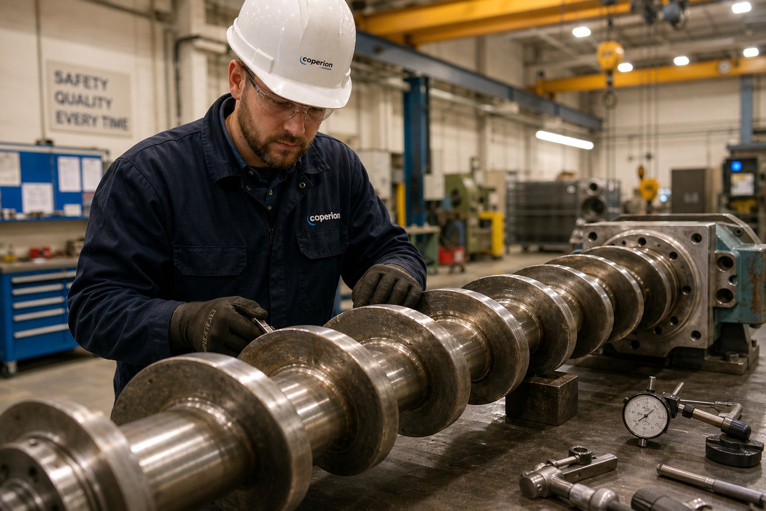
Here is a practical tip: when you pull twin screw elements for inspection, measure not just the outer diameter but also the flank thickness of each kneading disc. Flank wear that goes undetected eventually degrades self-wiping efficiency, widens residence time distribution, and creates the same stagnation zones that the intermeshing design was supposed to eliminate. Catching it early, before mixing quality declines, is far cheaper than reacting after off-spec product starts shipping.
Troubleshooting and wear management are ongoing operational concerns. But there is a longer-term, higher-stakes decision that determines how often you face these problems in the first place: the metallurgy of the barrel and screw components themselves. The steel grades, surface treatments, and wear-resistant alloys specified at purchase directly set the clock on when these wear patterns become production-limiting.
Barrel and Screw Metallurgy for Wear Resistance
Steel grades and surface treatments are not line items to gloss over during procurement. They are the single biggest lever controlling how many operating hours you extract from a screw and barrel set before clearance loss forces a replacement. The global feed screw and barrel market reached $1.86 billion in 2025, with over 54% of newly installed extruders now specifying bimetallic barrel construction. That shift reflects a hard-learned industry truth: matching alloy chemistry to your actual polymer and filler chemistry pays for itself many times over, while under-specifying metallurgy accelerates a costly replacement cycle.
Metallurgy Options for Barrels and Screws
Imagine your metallurgy selection as a tiered defense system. Each tier adds cost, but also multiplies service life under increasingly aggressive conditions. Here are the primary options you will encounter when specifying components from any reputable single screw extruder manufacturers or twin screw extruder manufacturers:
- Nitrided steel (4140 / 4340 baseline) - The cost-effective starting point for unfilled commodity polymers like PE, PP, and PS. Nitrogen diffusion at 480-530 degrees C produces a surface hardness of 950-1,100 HV to a case depth of 0.3-0.7 mm. The core remains tough, and dimensional distortion during treatment is minimal. The limitation? That hardened case is shallow. In abrasive service, the nitrided layer can wear through within 2,000-3,000 operating hours, exposing the softer substrate beneath and triggering rapid clearance loss.
- Through-hardened tool steels (D2, CPM 10V, CPM 15V) - When moderate to severe abrasion enters the picture, tool steels deliver hardness throughout the entire cross-section, not just at the surface. D2 (58-62 HRC) provides roughly 4-6x the abrasion resistance of nitrided 4140. CPM 10V, a powder metallurgy grade with uniformly distributed vanadium carbides, outperforms D2 by 3-5x in standardized ASTM G65 abrasion testing. For screws processing 30-60% glass-filled compounds, CPM 10V routinely exceeds 20,000 hours of service life. The raw material premium is 2.5-4x over D2, but total cost of ownership over 36 months almost always favors CPM grades in severely abrasive service.
- Bimetallic barrels with centrifugally cast linings - This construction bonds a wear-resistant alloy liner metallurgically inside a tough 4140 or 4340 outer shell. Two main liner families dominate. Iron-based bimetallic liners (high-chromium with embedded tungsten carbides, reaching 60-72 HRC bore hardness) handle general abrasive service from glass fibers and mineral fillers. Nickel-based bimetallic liners tackle corrosive environments, particularly PVC, CPVC, halogenated flame retardants, and fluoropolymers like PVDF, where hydrogen chloride or hydrogen fluoride attack would destroy conventional steels. Corrosive wear rates in PVC service drop 8-12x when switching from nitrided 4140 to nickel-alloy or Stellite-overlaid constructions.
- Tungsten-carbide-coated screw elements - Applied via HVOF (high-velocity oxygen fuel) thermal spray, WC-Co or WC-CrC-Ni coatings achieve coating hardness of 1,100-1,400 HV, approximately 70+ HRC equivalent. These coatings provide extreme abrasion resistance for the most demanding applications, such as high-loading mineral-filled compounds or carbon fiber reinforcements. One important caveat: WC coatings are brittle. On high-L/D screws that deflect under process loads, coating thickness should typically stay below 0.25 mm to prevent cracking or delamination.
How Abrasive and Corrosive Materials Drive Metallurgy Choices
Selecting the right tier is not guesswork. It is a direct function of what your extruder processes. Two factors dominate the decision.
Filler type and loading level determine abrasive severity. Glass fibers (Mohs 5.5-6.5) at loadings above 15% demand D2 minimum, with CPM 10V preferred above 30%. Softer mineral fillers like calcium carbonate and talc still drive meaningful wear at high loading levels above 50%. A practical rule of thumb from industry experience: for every 10% increment in hard filler loading above 20%, move up at least one tier in your alloy selection.
Chemical aggressiveness of the polymer system determines corrosion severity. Unfilled polyolefins present negligible corrosive attack. Rigid PVC generates moderate HCl at processing temperatures. Fluoropolymers like PVDF produce severe corrosive conditions requiring premium overlays. For any twin-screw extruder machine running halogenated compounds, nickel-based barrel liners and cobalt-chromium (Stellite) screw overlays are not optional upgrades; they are engineering requirements.
Here is where single screw and twin screw platforms diverge metallurgically. A single screw barrel experiences relatively uniform wear across the bore, concentrated along the flight-tip contact line throughout the compression and metering zones. Metallurgy selection focuses on providing consistent hardness across the full bore length. Twin screw barrels, by contrast, experience concentrated wear at the intermeshing zone, the apex region where the two bores overlap. Kneading block flanks and the barrel walls in this overlap area bear the heaviest abrasive and erosive loads. That is why a twin-screw extruder manufacturer specifying barrels for filled compound service will often recommend a higher-grade liner than what a comparable single screw application requires: the same abrasive filler causes more localized damage in the twin screw geometry.
Proper metallurgy selection extends barrel and screw life dramatically. Documented comparisons show bimetallic constructions delivering 4-8x the service life of monolithic nitrided screws in abrasive compounding applications. In one controlled comparison processing 45% CaCO3-filled polypropylene, a bimetallic screw with HVOF WC-17Co flight tip overlay showed just 0.12 mm of clearance loss at 4,500 hours, versus 0.8 mm for a nitrided 4140 screw, a projected 6.7x life extension. That translates directly into fewer unplanned shutdowns, lower replacement part inventories, and more consistent product quality across the service interval.
When sourcing replacement screw barrels or specifying metallurgy for new builds, engineers and procurement teams benefit from comparing options across different extruder platforms side by side. NANHAIYA's product collection provides direct specification comparison for single screw, parallel twin screw, conical twin screw, and injection molding screw barrel configurations, giving plant managers a practical starting point for evaluating metallurgy options against their specific processing requirements.
Metallurgy sets the wear clock. The extruder platform and screw configuration determine what the machine can process. But which combination is right for your specific application? That question calls for a structured decision framework, one that walks through every critical variable from material chemistry to budget constraints, and delivers a clear recommendation at the end.
Choosing the Right Extruder for Your Application
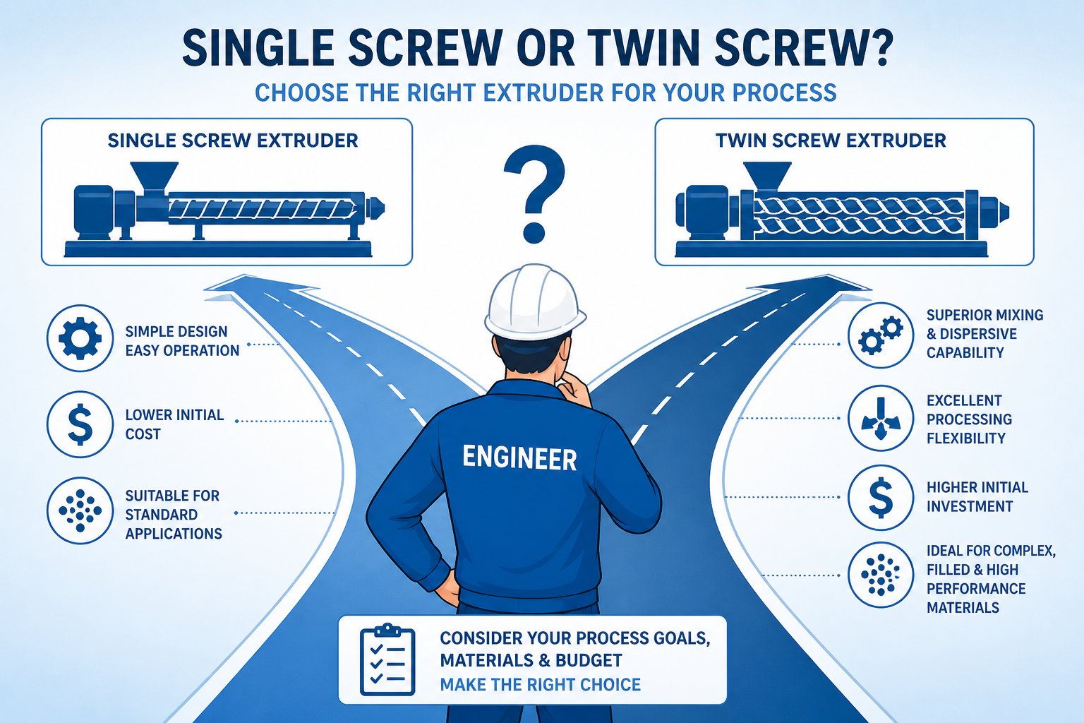
You have the technical knowledge: screw geometries, element configurations, metallurgy grades, troubleshooting maps. All the pieces are on the table. The challenge now is assembling them into a decision that holds up for the next decade of production. Picking between a single screw and twin screw extruder is not a one-variable problem, and treating it that way is exactly how plants end up overspending on capability they never use or, worse, underspecifying a machine that chokes on the first real production run.
What follows is a structured sequence of questions, designed to walk you from raw material chemistry to a defensible equipment recommendation. Answer them honestly, and the right platform will reveal itself before you ever request a quote.
Seven Questions to Guide Your Extruder Selection
- What material are you processing, and does it require intensive mixing or gentle conveying? Start here, always. A pre-compounded polyethylene pellet headed for a blown film die needs steady melt pumping, not dispersive mixing. A 40% CaCO3-filled polypropylene masterbatch needs the exact opposite. If your feed is a stable, homogeneous pellet and the formulation is already complete, single screw territory. If you are blending, filling, reacting, or devolatilizing inside the extruder barrel, twin screw territory.
- What is your required throughput range? Both platforms scale across a wide output spectrum, from laboratory twin screw extruder setups processing a few kilograms per hour to production machines pushing several tons per hour. But the economics shift at different scales. Single screw machines deliver the lowest cost per kilogram for high-volume, single-product lines. Twin screw systems justify their higher capital cost when the throughput requirement accompanies a complex formulation that demands active in-barrel mixing.
- Do you need modular screw configurability for multiple formulations? If your plant runs three products this year and expects eight next year, each with a different filler package, pigment load, or additive suite, you need the ability to reconfigure your screw profile without swapping the entire screw shaft. That modularity is native to twin screw platforms and essentially unavailable on single screw machines. Conversely, if you run a single product 24/7, that flexibility adds cost without adding value.
- Is self-cleaning important for frequent product changeovers? Every changeover on a non-self-wiping screw plastic extruder generates transition scrap, purge compound consumption, and lost production minutes. If your schedule demands daily color or material changes, the self-wiping geometry of an intermeshing twin screw extruder machine dramatically reduces that waste. Operations running the same material for weeks at a stretch gain little from self-cleaning capability.
- What is your capital budget vs. total cost of ownership tolerance? A single screw line might cost 40-60% less upfront than a comparably sized twin screw system. But energy-efficient drives can cut operational costs by 18-22% over five years, and twin screw platforms often reduce scrap rates and rework in mixing-intensive applications. Run the total cost of ownership calculation over your expected equipment lifespan, not just the purchase order value. A cheaper machine that produces 6% more scrap or requires an additional upstream compounding step is not actually cheaper.
- Do you require devolatilization or reactive processing capability? If your process involves removing moisture, solvents, or reaction byproducts from the melt, or if you need controlled chemical reactions (grafting, crosslinking, chain extension) to occur inside the barrel, twin screw architecture with multiple vent zones and narrow residence time distribution is the only viable path. Single screw venting capability is limited and cannot deliver the deep vacuum devolatilization that co-rotating systems achieve routinely.
- What are your wear and metallurgy requirements based on filler content? Heavily filled compounds (above 20% glass fiber or hard mineral) impose aggressive wear on both platforms, but the wear pattern differs. Twin screw intermeshing zones concentrate abrasive damage, requiring higher-grade metallurgy in those regions. Single screw wear distributes more evenly along the flight tips. Factor the cost of replacement elements, barrel relining, or bimetallic construction into your operating budget. A benchtop twin screw extruder running R&D trials on abrasive formulations still needs proper metallurgy; element replacement costs scale down in size but not in frequency.
The Core Decision Rule Simplified
After working through all seven questions, the answer usually collapses into a surprisingly clean principle:
Choose a single screw extruder for steady-state pumping of pre-compounded materials through a shaping die. Choose a twin screw extruder when the process demands mixing, compounding, devolatilization, or formulation flexibility inside the barrel.
That rule covers roughly 85% of real-world selection decisions. The remaining 15% involves edge cases where hybrid approaches, tandem lines, or emerging technologies enter the conversation. A plant processing lightly contaminated recycled HDPE into drainage pipe, for instance, might pair a twin screw compounding step with a single screw extrusion line downstream, using each platform exactly where its strengths apply.
The common mistake, worth repeating one final time, is treating twin screw as universally superior. The better machine is the one that solves the actual processing problem without adding unnecessary cost, cleaning, wear, and operator burden. Installing a co-rotating twin screw machine to pump pre-compounded PP pellets into a sheet die wastes capital, increases maintenance complexity, and delivers no measurable quality improvement. Conversely, asking a single screw machine to disperse nano-fillers into a polymer matrix guarantees poor results regardless of how many Maddock mixers you bolt onto the screw.
Emerging Extrusion Technologies Worth Watching
The single screw vs. twin screw framework has dominated polymer processing for decades. But the broader extrusion landscape continues to evolve, and two technologies deserve attention from forward-looking engineers.
Planetary roller extruders (PREs) use a central spindle surrounded by multiple smaller planetary screws that orbit inside a barrel with internal helical grooves. The geometry creates an enormous number of kneading contacts per revolution, delivering extremely gentle yet thorough mixing at remarkably low melt temperatures. PREs have carved out a niche in PVC calendering feed, thermally sensitive bioplastics, and specialty adhesive compounding where minimizing thermal degradation is paramount. Their throughput-to-footprint ratio is impressive, though capital costs and the specialized knowledge required for screw configuration currently limit adoption to specific high-value applications.
Triple screw extruders add a third intermeshing screw arranged in a triangular barrel configuration. According to GSmach's engineering analysis, the additional screw increases intermeshing points and shear zones, boosting throughput by 15-30% over comparable twin screw systems while maintaining lower melt temperatures through balanced shear distribution. Applications in high-fill compounding, masterbatch production, and biodegradable polymer blending are growing. Triple screw technology does not replace the fundamental single-vs.-twin decision framework, but it extends the performance envelope for operations that have already outgrown what a twin screw platform can deliver.
Neither technology is mainstream yet. But both signal a clear industry direction: more mixing contacts, lower melt temperatures, and broader processing windows. If you are specifying equipment for a facility expected to run beyond 2030, keeping these options on your radar makes practical sense.
Your Next Step
The right extruder selection starts with answering the seven questions above against your specific material, formulation, and production requirements. From there, the focus shifts to specifying the components that determine long-term performance: screw and barrel metallurgy, element configurations, and spare part strategies matched to your chosen platform.
Engineers and plant managers comparing screw barrel specifications across single screw, parallel twin screw, and conical twin screw configurations can use NANHAIYA's product collection as a practical starting point for side-by-side evaluation of replacement components and spare parts. Having direct specification comparisons across extruder platforms streamlines procurement and ensures metallurgy choices align with the wear and corrosion demands identified during the selection process.
Pick the right architecture, specify the right materials of construction, and your extruder will run profitably for years. Pick wrong, and you will pay for it every single production day until you correct the mistake.
Frequently Asked Questions About Single Screw and Twin Screw Extruders
1. What is the main difference between a single screw and twin screw extruder?
The core difference lies in how each machine conveys and processes material. A single screw extruder relies on drag flow, where polymer adheres to the barrel wall and the rotating screw pulls it forward, making it ideal for steady-state pumping of pre-compounded pellets. A twin screw extruder uses two intermeshing screws that actively transfer material between them in a figure-eight pattern, delivering far superior dispersive and distributive mixing. This makes twin screw systems the go-to choice for compounding, reactive extrusion, devolatilization, and any application requiring intensive in-barrel blending of multiple components.
2. When should I choose a single screw extruder over a twin screw extruder?
A single screw extruder is the better choice when your process involves pumping a homogeneous, pre-compounded resin through a shaping die, such as blown film, cast sheet, pipe, or profile extrusion. If the formulation is already complete and the material flows freely as pellets, a single screw machine delivers comparable output at 40-60% lower capital cost, simpler operation, and reduced maintenance complexity. It also generates excellent die-head pressure, which is critical for restrictive die geometries. However, if your process requires blending fillers, dispersing pigments, or handling powder feeds, a twin screw platform becomes necessary.
3. What is the difference between co-rotating and counter-rotating twin screw extruders?
Co-rotating twin screw extruders have both screws spinning in the same direction, creating a figure-eight flow path that delivers excellent self-wiping, narrow residence time distribution, and strong dispersive and distributive mixing. They dominate polymer compounding, reactive extrusion, and pharmaceutical hot-melt extrusion. Counter-rotating extruders spin the screws in opposite directions, producing a calendering effect in the nip region with gentler overall shear. This makes them well-suited for heat-sensitive materials like rigid PVC, where aggressive mixing would cause degradation. Choosing between them depends primarily on whether your material needs intensive mixing or gentle, positive-displacement conveying.
4. How do screw elements affect twin screw extruder performance?
Twin screw extruders use modular elements that slide onto a splined shaft, and each element type serves a distinct purpose. Conveying elements transport material forward with minimal shear. Kneading blocks, configured at 30-degree, 60-degree, or 90-degree stagger angles, control mixing intensity from gentle distributive blending to aggressive dispersive deagglomeration. Toothed mixing elements split and recombine the melt stream for uniform additive distribution. Reverse elements create backflow dams that build pressure and extend residence time. Engineers sequence these elements into custom screw profiles tailored to specific formulations, adjusting shear, temperature, and dwell time at every point along the barrel. For specification comparison across screw barrel configurations, resources like NANHAIYA's product collection at nhyscrews.com offer side-by-side evaluation tools.
5. What metallurgy should I specify for extruder screws and barrels processing filled compounds?
Metallurgy selection depends on filler type, loading level, and chemical aggressiveness. For unfilled commodity polymers, nitrided 4140 steel provides a cost-effective baseline. Glass fiber loadings above 15% demand through-hardened tool steels like D2, while loadings above 30% favor powder metallurgy grades like CPM 10V that offer 3-5x better abrasion resistance than D2. Bimetallic barrels with centrifugally cast iron-boron linings handle general abrasive fillers, while nickel-based liners are essential for corrosive polymers like PVC or fluoropolymers. Twin screw systems require particular attention because wear concentrates at the intermeshing zone, often justifying a higher metallurgy tier than a comparable single screw application would need.
Written by
Nanhaiya Technical Team
Zhoushan Nanhaiya Plastic Machinery Co., Ltd.
The Nanhaiya technical team supports screw and barrel manufacturing projects through application review, technical communication, custom manufacturing coordination, and production and quality control.
Discuss Your Application
Related Articles
More insights on screw barrel technology and plastics processing.

What Nobody Tells You About Screw Barrel For Plastic Machine Design
Oct 10, 2026
Learn how screw barrel for plastic machine design affects melt quality, throughput, and wear life. Covers geometry, resin matching, troubleshooting, and sourcing.
Read Article
Single Screw Extruder for Sheet: Stop Guessing, Start Specifying
Oct 9, 2026
Learn how to specify a single screw extruder for sheet production. Covers screw geometry, resin-specific processing, troubleshooting, and maintenance best practices.
Read Article
PE Pipe Extruder Machine: What Datasheets Won't Tell You
Oct 9, 2026
Learn how a PE pipe extruder machine works, key specs explained, material grade selection, maintenance tips, and buyer guidance beyond the datasheet.
Read ArticleLooking for something else?
Search by material, symptom or product and jump straight to the relevant page.
These are navigation suggestions based on keyword matching — not a quotation, not a delivery commitment, and not a substitute for engineering review. Final specification is confirmed by our engineers against your drawings and processed material.
Need help with screw barrel selection?
Share your machine model, processed material and application. Our team can help with pricing and technical support.