

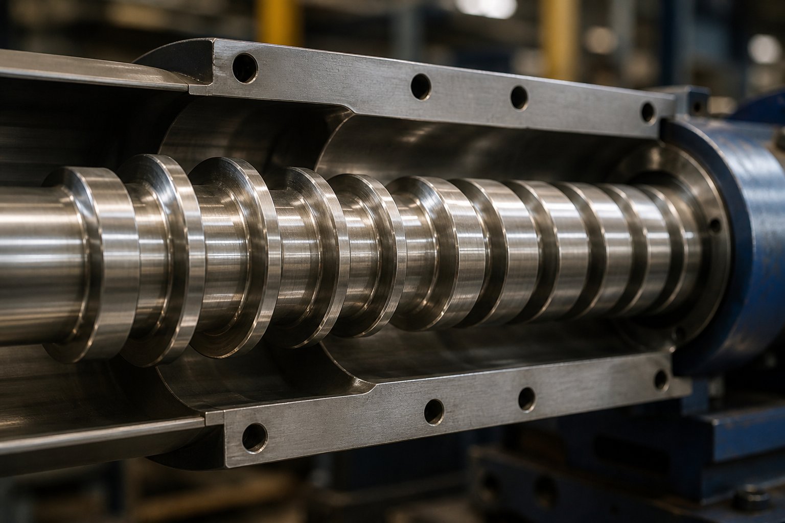
What a Single Extruder Screw Does and Why It Matters
Every plastic pipe, blown film, and extruded profile starts the same way: solid pellets or flakes drop from a hopper into a heated barrel, and a single rotating component does the heavy lifting of turning them into a shaped product. That component is the single extruder screw — and its design touches virtually every quality and cost metric on the production floor.
Defining the Single Extruder Screw and Its Role
A single extruder screw is a helical-flighted shaft that rotates inside a heated barrel to convey, compress, and melt polymer into a homogeneous, pressurized stream for shaping through a die. It accepts raw material — pellets, powder, regrind flakes, or a combination — at the feed throat and progressively transforms that loose solid into a uniform molten flow ready for downstream shaping. The screw accomplishes this through three interdependent actions: solids conveying driven by frictional drag, melting driven by compression and shear, and pressure generation driven by viscous pumping in a shallow metering channel.
In a single screw extruder, no other component exerts as much influence over the process. The barrel supplies heat, the die shapes the product, and the drive delivers torque — but it is the screw geometry that dictates how efficiently energy transfers into the polymer, how uniformly the melt reaches the die, and how stable the output rate remains over time. Melt temperature, pressure consistency, mixing quality, and throughput capacity all trace back to screw design decisions.
The screw is responsible for roughly 80 percent of the work that determines final product quality in a single-screw extrusion line — understanding its design is not optional for serious processors.
This reality applies whether you are running HDPE pipe, cast film, PVC profiles, or post-consumer recycled flake. The screw is not a commodity spare part you swap in and forget. It is a precision processing tool, and the difference between a well-matched design and a generic replacement can show up as lost output, scrap, excessive energy draw, or all three at once.
Why Screw Design Knowledge Matters for Processors
Imagine a blown-film line that surges every few minutes, producing gauge bands that push finished rolls out of spec. Or a pipe extrusion line where gels and unmelt particles cause rejected lengths. These are not rare events — they are everyday problems, and the root cause frequently sits inside the barrel. Surging, melt fracture, poor gauge uniformity, black specks, and excessive melt temperature are among the most common extrusion defects, and each one can be traced to a mismatch between screw geometry and the polymer being processed.
A twin screw extruder offers modular screw elements that processors can rearrange to fine-tune mixing and conveying. A single screw extruder, by contrast, typically uses a one-piece screw whose geometry is fixed at manufacture. That means getting the design right up front — or selecting the correct replacement — carries far greater consequences. There is less room to compensate on the fly.
Yet many processors still treat screw selection as an afterthought, reordering the same "general-purpose" design year after year without evaluating whether it matches their current resin, output target, or product specification. The cost of that approach shows up quietly: in slightly higher specific energy consumption, in a few percentage points of scrap, in melt temperatures that creep above the ideal window.
This article is built as a practitioner-first engineering resource. In the sections ahead, you will find a detailed walkthrough of the three functional zones that define every screw's performance, the geometry parameters that control melt quality and throughput, the design variants available for specific challenges, polymer-specific screw selection guidance, a head-to-head comparison with twin screw extrusion, materials and wear-resistance strategies, a structured troubleshooting guide, and a practical specification framework. Each section connects screw design principles to the production outcomes they affect — because understanding the engineering behind your screw is the fastest path to better output on the floor.
Three Functional Zones That Drive Extrusion Performance
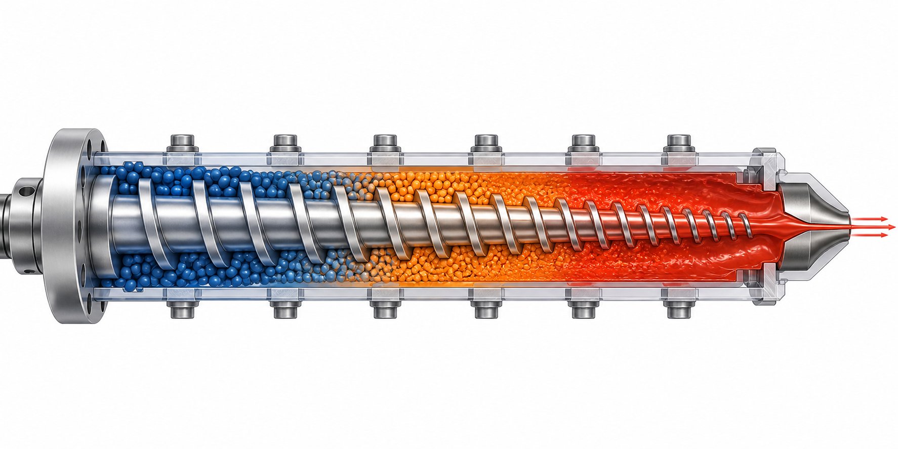
Picture a single extruder screw laid out on a bench, stripped from its barrel. You will notice the flight depth is not uniform — it changes deliberately along the length, carving the screw into three distinct regions. Each region handles a different phase of the polymer's transformation from loose solid to pressurized melt. Get the design of any one zone wrong, and the problems cascade downstream into your product. Here is what happens inside each zone and why the polymer science behind it matters for every single screw extruder machine on your floor.
Feed Zone — Solids Conveying and Intake
The feed zone is the entry point. Pellets, regrind, or powder drop from the hopper into deep, constant-depth screw channels, and the screw's job here is deceptively simple: move solids forward as fast and as steadily as possible. No melting occurs yet — this is purely a conveying task — but the physics governing it are anything but straightforward.
Solids conveying in this zone depends almost entirely on friction. For the polymer to travel forward, it must grip the barrel wall more than it grips the screw root. Think of it this way: if pellets spin with the screw instead of sliding along the barrel, nothing moves downstream. The friction ratio between the barrel surface and the screw surface is the controlling factor, and it is why barrel surface finish matters so much. A polished screw root reduces adhesion to the screw, while a slightly roughened or textured barrel inner surface increases grip — both pushing the friction balance in the right direction.
Flight depth in the feed zone is the deepest anywhere on the screw. Deeper channels hold more material per turn, increasing the volumetric intake rate. However, depth alone is not the whole story. If the channel is too deep relative to the pellet size, the solid bed can become loosely packed and convey erratically, leading to output fluctuations before melting even begins.
For slippery, high-density polymers like HDPE, standard smooth-bore feeding sometimes struggles to develop enough frictional drag. This is where grooved-feed-throat designs come in — axial or helical grooves machined into a water-cooled barrel liner at the feed opening physically lock pellets against the barrel, converting solids conveying from a friction-dependent process into something closer to positive displacement. The payoff is higher and more stable throughput, though it comes with trade-offs in screw design downstream, as veteran extrusion engineer Allan Griff notes: a grooved feed section typically demands a shallower feed zone and deeper metering zone, often with additional mixing hardware at the screw tip.
Compression Zone — Melting and Densification
This is where the real transformation happens. As the channel depth progressively decreases, the solid bed is squeezed against the barrel wall — and the combination of conducted heat from the barrel and viscous shear energy begins melting the polymer.
The mechanism is more structured than you might expect. In the 1960s, researcher Zehev Tadmor conducted landmark experiments — stopping extruders mid-run, cooling the barrel, pulling the screw, and slicing cross-sections of the solidified channel contents. What he found became the foundation of screw extrusion science: a distinct melting model showing that a thin melt film forms at the barrel surface, gets dragged by barrel rotation across the channel width, and accumulates in a growing melt pool on one side of the channel. Meanwhile, the solid bed on the opposite side shrinks progressively in width as material melts off its surface.
Imagine the cross-section of the screw channel at any point in the compression zone: on one side sits a compacted wedge of still-solid polymer, and on the other side sits a growing pool of melt. The melt film between the solid bed and the barrel is where the energy transfer is most intense — heat conducts down from the hot barrel wall while the relative motion between barrel and solid generates viscous dissipation in the thin film. As the solid bed moves forward and the channel gets shallower, more material melts, the melt pool widens, and the solid bed narrows until — ideally — all solids are consumed before the polymer exits this zone.
The compression ratio is the critical design variable here. Defined as the ratio of channel depth in the feed zone to channel depth in the metering zone, it controls how aggressively the solid bed is compacted. This ratio must match the polymer's bulk-density-to-melt-density change. A polymer that undergoes a large volume reduction upon melting — like semicrystalline HDPE — needs a higher compression ratio to prevent the channel from becoming partially empty as the solid densifies. An amorphous polymer like polystyrene, which changes density far less during melting, requires a lower compression ratio. Mismatching this parameter is one of the most common and most damaging screw design errors in practice.
The length of the compression zone matters too. A gradual taper spreads the melting work over more screw turns, reducing the risk of solid bed break-up — a phenomenon where chunks of unmelted polymer fracture away from the solid bed and get carried into the melt stream, causing surging and unmelts at the die. Research at Paderborn University confirmed that solid bed break-ups become more frequent at higher screw speeds and with shorter compression zones, reinforcing why compression zone design deserves careful attention.
Metering Zone — Melt Homogenization and Pressure Generation
By the time polymer reaches the metering zone, it should be fully — or very nearly — molten. The channel depth here is constant and shallow, and the zone serves two tightly coupled purposes: homogenizing the melt temperature and generating the pressure needed to push material through the screen pack and die.
The shallow channel creates high shear rates, which help mix any remaining thermal gradients in the melt. As Paulson Training resources describe, plastic in the metering section moves in a spiraling, recirculating pattern — dragged forward along the barrel surface, turned downward by the pushing flight, crossing the channel floor, and pushed back up by the trailing flight. This constant reorientation is what blends hotter and cooler melt streams into a uniform output.
Output from the extrusion screw is governed by the balance of two opposing flows. Drag flow is the forward-pumping action created by the barrel surface moving relative to the screw — it is proportional to screw speed, channel width, and channel depth. Pressure flow is the backward leakage driven by the high head pressure at the screw tip — it pushes melt back up the channel and is proportional to the cube of channel depth. The net output is drag flow minus pressure flow. This relationship explains a key engineering trade-off: a deeper metering channel increases drag flow capacity but also increases pressure-flow sensitivity, making output less stable against head-pressure changes. A shallower channel pumps more consistently against pressure but limits maximum throughput and generates more shear heat.
Melt pressure in the metering section typically ranges from roughly 1,000 to 7,000 psi (70 to 480 bar), depending on die resistance and screw geometry. If pressure flow ever approaches drag flow, net output drops toward zero, residence time skyrockets, and the polymer degrades from excessive shear heating — a scenario every processor should understand and avoid.
| Zone | Primary Function | Typical Flight Depth | Key Design Variable | Failure Mode if Improperly Designed |
|---|---|---|---|---|
| Feed | Solids intake and conveying | Deepest | Channel depth and barrel surface friction | Output instability, inconsistent feeding, pellet bridging |
| Compression (Transition) | Melting, densification, and air expulsion | Progressively decreasing | Compression ratio and taper length | Solid bed break-up, surging, unmelted particles in output |
| Metering | Melt homogenization and pressure generation | Shallowest (constant) | Channel depth (controls drag flow vs. pressure flow balance) | Poor melt uniformity, excessive shear heating, pressure instability |
These three zones work as an integrated system — not isolated stages. A feed zone that conveys too much material for the compression zone to melt will push unmelts into metering. A compression zone with an overly aggressive taper can fracture the solid bed and destabilize pressure all the way to the die. And a metering zone with the wrong depth can either starve the die or overheat the polymer. The geometry that links these zones together — L/D ratio, flight dimensions, helix angle, and compression ratio — is where screw performance is truly engineered.
Key Geometry Parameters That Control Screw Performance
Knowing what each zone does is one thing. Knowing which dimensions actually determine how well it does its job is another — and that distinction separates processors who react to problems from those who prevent them. Every plastic single screw extruder on the market ships with a screw defined by a handful of geometric parameters, yet even small changes in any one of them can shift melting location, alter shear intensity, or destabilize output. Here is what each parameter controls and why it matters for your specific polymer and application.
L/D Ratio and Its Influence on Residence Time
The length-to-diameter ratio — screw flighted length divided by its nominal bore diameter — is the primary sizing parameter for any single screw extrusion system. It tells you how much barrel length the polymer has to travel through, and by extension, how much time and energy the screw can invest in melting, mixing, and pressure development.
A longer L/D gives the screw more real estate to complete each task. Feed, compression, and metering zones can each be stretched, providing gentler compression tapers, longer melting paths, and extended metering sections for better melt homogenization. Standard extrusion engineering references — notably Chris Rauwendaal's Polymer Extrusion — discuss common L/D ranges spanning from around 20:1 on the shorter end to 36:1 or more for high-performance applications. Film and sheet lines frequently run at the higher end of that range because they demand superior melt uniformity, while simpler profile extrusions may work well with shorter screws.
The trade-off, however, is residence time. A longer screw holds polymer in the barrel for more revolutions, which increases its cumulative shear history and thermal exposure. For heat-sensitive polymers like PVC or certain bioplastics, extended residence time can push the material dangerously close to degradation thresholds. So the "right" L/D is never simply "longer is better" — it is a balance between melting capacity and thermal safety that depends entirely on the resin's processing window.
Flight Depth, Pitch, and Helix Angle
These three dimensions work together to define the screw channel — the helical pathway carved between the flights where all conveying, melting, and pumping actually occur.
Flight depth (channel depth) is the distance from the flight tip down to the screw root. It directly controls two competing factors: channel volume and shear rate. A deeper channel holds more material per turn, increasing potential throughput — but it also reduces the shear rate the polymer experiences, because shear rate in a screw channel is proportional to screw surface speed divided by channel depth. In the metering zone of a screw plastic extruder, where uniform melt quality is the goal, flight depth becomes the single most influential dimension. Too shallow, and viscous dissipation generates excessive heat. Too deep, and the melt lacks the shear mixing needed for thermal homogeneity.
Pitch is the axial distance the flight advances in one full revolution. Most general-purpose screws use a "square pitch" — meaning the pitch equals the screw diameter — which provides a helix angle of approximately 17.66 degrees. This geometry has proven to offer a practical balance between forward conveying efficiency and the cross-channel shear that drives melting. Increasing pitch beyond square moves more material per revolution but reduces the number of flight turns available for melting and pressure generation along a fixed barrel length.
Helix angle is mathematically linked to pitch and diameter, but it is worth understanding independently because it governs the relative magnitudes of drag flow and pressure flow. A steeper helix angle favors conveying; a shallower angle favors pressure buildup. In practice, most single screw extrusion designs stay close to the square-pitch geometry because it sits near the optimum for net output under typical die-resistance conditions.
Compression Ratio — Matching the Polymer
If you could pick only one parameter to get right, compression ratio would be a strong candidate. Defined as the ratio of feed-zone channel depth to metering-zone channel depth, it dictates how much the solid bed is compacted as it transitions to melt — and it must correspond to the density change the polymer undergoes during that transition.
Why does this matter so much? When a polymer melts, it typically occupies a different volume than it did as a packed solid. Semi-crystalline materials undergo a particularly large density shift because their crystalline structure collapses into a denser amorphous melt. If the compression ratio does not accommodate that volume change, problems appear immediately: too little compression leaves partially empty channels and erratic melting, while too much compression generates excessive pressure in the transition zone, potentially causing melt-flow instability or mechanical overload.
General guidance for matching compression ratio to polymer type:
- Semi-crystalline polymers (HDPE, LLDPE, PP, nylon, PET) — typically require higher compression ratios because the density increase upon melting is substantial. The screw must squeeze the solid bed enough to keep channels fully packed as volume shrinks.
- Amorphous polymers (PS, ABS, PC, PMMA) — require lower compression ratios because density changes minimally between solid and melt states. Excessive compression for these materials generates unnecessary shear heat and can degrade the polymer.
- PVC and thermally sensitive compounds — demand the lowest compression ratios and the gentlest tapers to avoid localized overheating that triggers degradation.
- Filled or reinforced compounds — may need adjusted compression ratios to account for the filler's effect on bulk density and flow behavior in the solid state.
Incorrect compression ratio ranks among the most common root causes of poor melt quality in single screw extrusion. Processors who switch resin families on the same extruder without evaluating this parameter often discover — through surging, gels, or erratic melt temperature — that a screw optimized for one polymer can be entirely wrong for another.
Screw geometry is never one-size-fits-all. Every parameter — L/D, flight depth, pitch, and compression ratio — must be evaluated relative to the specific polymer and the application's output and quality targets.
These dimensional relationships set the foundation for the screw's behavior, but geometry alone does not tell the full story. Specialized design features — barrier flights, mixing elements, vented two-stage layouts — build on this geometric foundation to solve problems that a conventional three-zone screw cannot address on its own.
Screw Design Types and When to Use Each One
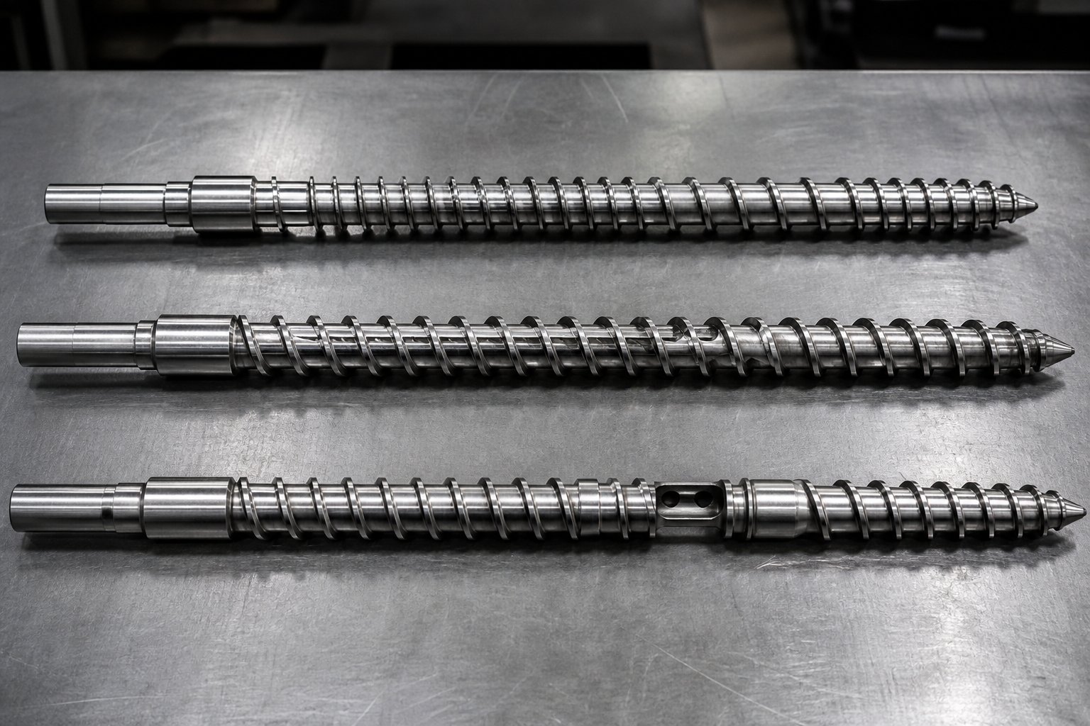
A conventional three-zone screw handles straightforward extrusion jobs well — but "straightforward" has its limits. When you push output higher, add colorant or mineral filler, switch to a harder-to-melt resin, or start processing post-consumer regrind, a standard single-flight geometry can hit a performance ceiling that no temperature adjustment or speed change will overcome. That is exactly why specialized screw designs exist. Each one targets a specific bottleneck — incomplete melting, poor mixing, or trapped volatiles — and understanding what each variant solves is the fastest way to stop fighting process problems that originate inside the barrel.
Barrier Screws — Separating Solids from Melt
Imagine slicing a cross-section through the compression zone of a conventional screw. You would see a shrinking solid bed on one side and a growing melt pool on the other, sharing the same channel with only a thin melt film between them. At moderate output rates, this arrangement works. But ramp up screw speed or switch to a slow-melting resin, and chunks of unmelted polymer can break away from the solid bed, drift into the melt pool, and ride all the way to the die — appearing as fisheyes, gels, or hard spots in your product.
A barrier screw eliminates this failure mode by adding a secondary flight — the barrier flight — inside the compression zone. This second flight runs at a slightly smaller clearance than the primary flight, creating two distinct channels: a solids channel and a melt channel. As polymer melts at the barrel wall, only the thin melt film can pass over the barrier flight into the melt channel, while any still-solid material stays trapped in the solids channel until it too melts. The solids channel progressively narrows along the screw length as the melt channel widens, so by the end of the barrier section, essentially no unmelted polymer can pass through.
The practical benefits boil down to two things: more complete melting and more stable output. A peer-reviewed analysis published in Polymers confirms that the second flight in the compression zone promotes and stabilizes polymer melting — which is precisely why barrier designs became widespread in high-output film, sheet, and pipe applications. Extrusion authority Chris Rauwendaal explains that because the solids channel shrinks to nothing by the end of the barrier section, the design physically prevents unmelted particles from reaching the metering zone.
When does a barrier screw earn its higher cost? Consider it whenever you see these scenarios on a single screw extrusion machine:
- Unmelted particles persist in the product despite raising barrel temperatures
- Output surges cyclically, suggesting solid-bed breakup in the compression zone
- You need to increase throughput beyond what a conventional screw can melt cleanly
- The resin is semi-crystalline (PE, PP) and difficult to melt uniformly at high speeds
One caveat worth noting: a barrier screw must be designed for the specific material. The barrier flight clearance, channel geometry, and compression profile all need to match the polymer's melting rate. A poorly matched barrier screw can actually cause solid-bed plugging and create its own version of surging — a reminder that "barrier" is not a generic upgrade but a precision engineering solution.
Mixing Elements — Dispersive vs. Distributive
Even a perfectly melted polymer stream can produce a bad product if the mixing is inadequate. Color streaking, filler agglomeration, additive inconsistency — these defects all point to the same gap: the screw lacks the ability to blend components uniformly. A conventional three-zone design offers minimal mixing because the helical channel simply shears material in one dominant flow pattern. Dedicated mixing elements, typically added near the screw tip after the metering zone, solve this problem — but the type of mixing element you choose depends entirely on what needs to be mixed.
The distinction comes down to two categories that every processor should understand:
Dispersive mixing breaks things apart. It forces the melt through narrow gaps at high shear stress, fracturing agglomerates — pigment clumps, gel particles, unmelted clusters — into smaller pieces. The classic dispersive mixer is the Maddock section (also known as a LeRoy or fluted mixer). It uses alternating in-flow and out-flow flutes separated by a barrier land with a tight clearance. Polymer entering the in-flow flute must cross over the barrier to exit through the out-flow flute, and in doing so it passes through a high-shear gap that crushes agglomerates and acts as a melting checkpoint. Nothing unmelted or poorly dispersed gets through without being subjected to intense shear.
Distributive mixing spreads things around. Instead of breaking particles apart, it repeatedly divides and recombines the melt stream to create uniform spatial distribution — picture shuffling a deck of cards over and over until every card is evenly interspersed. Pin mixing sections achieve this by placing rows of pins protruding from the screw root that split and rejoin the melt flow with each row. Pineapple mixers use intersecting diamond-shaped channels to divide and converge the flow at multiple angles, achieving what extrusion engineers call chaotic mixing. Both generate far less shear than a Maddock, making them well suited for heat-sensitive materials where aggressive shear would degrade the polymer.
Veteran extrusion engineer Jim Frankland highlights this practical distinction in Plastics Technology: the Maddock is primarily a dispersive mixer — melt passes over a narrow clearance under high shear — while pin and pineapple designs are primarily distributive, dividing and reorienting the melt with much less shear. He also notes a pairing rule that catches many processors off guard: distributive mixers are usually the better choice to add onto a barrier screw. Why? Because the barrier section already handles melting thoroughly, and stacking a high-shear Maddock on top of it often just overheats the melt and increases pressure drop without adding meaningful benefit.
| Mixing Element | Mixing Type | Best Use Case | Pressure-Drop Characteristics |
|---|---|---|---|
| Maddock (Fluted / LeRoy) | Dispersive (high shear) | Breaking pigment clumps, gels, and hard agglomerates; melting checkpoint | Moderate to high — restricts flow through barrier clearance |
| Pin Mixer | Distributive (low shear) | Even blending of color, additives; shear-sensitive polymers | Can be substantial — depends on pin count and row spacing |
| Pineapple Mixer | Distributive (moderate shear) | General-purpose blending; color homogenization | Moderate — intersecting channels create some restriction |
| Egan / Combined Designs | Both dispersive and distributive | Applications needing both agglomerate breakup and uniform distribution | Medium to high — more complex geometry increases resistance |
Choosing the wrong type is a common and costly mistake. A Maddock section on a shear-sensitive PVC compound risks thermal degradation and corrosive off-gassing. A pin mixer on a heavily pigmented masterbatch leaves hard pigment clumps intact because it lacks the shear to fracture them. Match the mixing element to the job — not the other way around.
Vented and Two-Stage Screw Designs
Some polymers carry baggage that no amount of melting or mixing can fix — moisture trapped inside hygroscopic pellets, volatile residues in recycled feedstock, or reaction byproducts released during processing. If these volatiles remain in the melt, they show up as bubbles, voids, splay marks, or molecular weight loss in the finished product. Conventional pre-drying can reduce moisture levels, but for certain materials and applications, the only reliable solution is to remove volatiles directly from the melt inside the extruder itself.
That is the job of a two-stage (vented) screw. Picture a screw with two complete functional sequences stacked end to end. The first stage — feed, compression, and a short metering section — melts the polymer and builds initial pressure. Then the channel depth suddenly increases in a decompression zone, dropping the pressure to near atmospheric levels and opening up free surface area in the partially filled channel. A vent port in the barrel at this location allows moisture, trapped air, and other volatiles to escape — either to atmosphere or under applied vacuum for more aggressive devolatilization. The second stage then re-compresses and meters the now-devolatilized melt to the die.
As extrusion consultant Jim Frankland explains in Plastics Technology, proper vent design is far more nuanced than simply deepening the channel. The forward transport in the decompression zone depends on the width of polymer in contact with the barrel wall and the melt viscosity at that point — not just the channel depth. Getting the decompression geometry wrong can cause vent flooding, where the melt backs up through the vent port, defeating the entire purpose.
Vented two-stage designs are standard for several important applications:
- PET extrusion — PET is highly hygroscopic and will hydrolyze (lose molecular weight) if moisture is present during melt processing. Vented screws remove residual moisture in-line.
- Recycled feedstocks — Post-consumer regrind carries moisture, printing ink volatiles, adhesive residues, and other contaminants. A single screw extrusion machine processing recycled flake frequently relies on vented two-stage screws to produce clean, bubble-free melt.
- Nylon and other hygroscopic engineering resins — Even with pre-drying, residual moisture can cause problems at high output rates, making in-barrel devolatilization a valuable safety net.
- Screw extruder granulator lines — Pelletizing operations handling recycled or moisture-laden materials benefit from vent-enabled volatile removal before strand or underwater pelletizing.
Two-stage vented screws represent the most complex single-screw design variant. They can incorporate barrier flights in the first stage for enhanced melting and distributive mixing elements in the second stage for melt homogenization — essentially combining every design feature discussed above into a single integrated tool. The trade-off is cost, length requirements (these screws typically need higher L/D ratios to accommodate both stages), and greater sensitivity to process conditions. But for applications that demand devolatilization, no simpler screw design can substitute.
Knowing which design variant to deploy — barrier, mixing section, vented two-stage, or a combination — is only half the equation. The other half is matching that design to the specific polymer family being processed, because each resin brings its own melting behavior, thermal sensitivity, and mixing demands to the table.
Matching Screw Design to Your Polymer Type
Every polymer melts differently, resists shear differently, and degrades at a different threshold. A screw that runs HDPE beautifully can scorch PVC within minutes. One that handles polystyrene with ease may leave nylon riddled with moisture-driven voids. So how do you match the screw to the material? The answer lives in the polymer science itself — crystallinity, thermal sensitivity, melt viscosity, and bulk density each point toward a specific screw configuration. Here is a practical breakdown by polymer family, grounded in the principles and geometry covered in earlier sections.
Polyolefins, Styrenics, and Engineering Resins
Polyolefins — HDPE, LDPE, LLDPE, and polypropylene — are the workhorses of single screw plastic extruder applications. They share a common trait: semi-crystalline structure. When these polymers melt, their crystalline regions collapse, producing a significant density increase. That volume change demands moderate-to-high compression ratios, typically in the 3.0:1 to 4.0:1 range, to keep the metering channel fully packed and pressurized as the solid bed shrinks. Polyolefins are also relatively tolerant of shear, so they benefit from barrier screw designs at high output rates — the barrier flight prevents solid-bed breakup that would otherwise limit throughput on a conventional three-zone geometry.
Styrenics tell a very different story. Polystyrene and ABS are amorphous, meaning they lack crystalline structure entirely. Their density changes very little between solid and melt states, so the screw does not need to compact material as aggressively. Compression ratios in the 2.5:1 to 3.0:1 range are typical. Equally important, these resins are more sensitive to shear-induced overheating than polyolefins. A screw designed for HDPE would generate unnecessary viscous dissipation when running ABS, pushing melt temperature above the ideal processing window and risking surface defects or yellowing.
Engineering resins like nylon (PA6, PA66) and PET introduce another variable: moisture sensitivity. Both are hygroscopic — they absorb atmospheric moisture that, if present during melt processing, causes hydrolytic degradation and molecular weight loss. Even aggressive pre-drying cannot always eliminate residual water content at high throughput rates. This is why engineering resins often require vented two-stage screws with in-barrel devolatilization capability. PET, with its moderate heat sensitivity, pairs well with medium compression ratios around 2.5:1 to 3.5:1, while nylon's semi-crystalline nature pushes compression ratios somewhat higher.
PVC and Thermally Sensitive Polymers
If polyolefins are forgiving, PVC is the opposite. Processing PVC demands a screw design philosophy built entirely around damage avoidance — and the consequences of getting it wrong are severe.
PVC degrades rapidly when exposed to excessive heat or shear. As the polymer chain breaks down, it releases hydrochloric acid (HCl) — a corrosive gas that attacks metal surfaces inside the barrel and accelerates further degradation in a destructive feedback loop. Viplas engineering resources identify four critical requirements for PVC processing hardware: corrosion resistance, abrasion resistance, specialized geometry, and precise temperature control.
What does "specialized geometry" mean in practice? Low compression ratios — typically between 1.5:1 and 2.5:1 for rigid PVC — to minimize the shear energy input that would overheat the resin. Gentle, gradual compression tapers that avoid localized hot spots. Shallow metering depths designed to reduce viscous dissipation. And critically, no dead spots — stagnant corners in the screw channel where material could hang up, overheat, and char. Those blackened particles then break free and contaminate the product stream.
Screw and barrel metallurgy also changes for PVC. Standard nitrided steel cannot withstand prolonged HCl exposure. Processors running PVC typically need stainless steel or nickel-alloy screws, bimetallic barrel liners with corrosion-resistant inner layers, or specialized PVD coatings that harden the surface while protecting against chemical attack. Running PVC on a screw designed for polyethylene is not just suboptimal — it risks both product failure and expensive equipment damage.
Other thermally sensitive polymers, such as EVOH and certain bioplastics, share PVC's need for low shear and short residence time, though without the corrosion dimension. The design principle remains the same: gentle compression, minimal dead volume, and precise control over shear heating.
Filled, Reinforced, and Recycled Materials
Adding glass fibers, mineral fillers, or recycled content to a compound changes the demands on a single extruder screw in ways that go beyond simple melting behavior. The challenges fall into two categories: abrasive wear and unpredictable feed behavior.
Glass-fiber-reinforced compounds and mineral-filled masterbatches (talc, calcium carbonate, TiO2) are abrasive. Those hard particles grind against flight lands, barrel walls, and screw roots with every revolution. Timothy Womer's analysis in SpecialChem shows that fillers like mica and fiberglass cause aggressive wear concentrated in the feed section and early transition zone, where the polymer is still solid and the filler particles are most exposed. The wear pattern appears on the push side of the flight and along the screw root — exactly where unmelted pellets with filler at their surface press hardest against metal.
Protection requires harder materials: nitrided steel as a minimum baseline, bimetallic coatings or tungsten-carbide encapsulation for moderate filler loads, and fully encapsulated screw roots for highly filled compounds. The choice is an economic calculation — the upfront cost of a wear-resistant screw versus the production losses and replacement frequency of a standard one.
Compression ratio also shifts for filled materials. Because the filler does not melt or compress during processing, the screw's volumetric compression must account for the reduced percentage of polymer that actually changes state. Womer notes that a screw for unfilled polypropylene typically uses a compression ratio in the 3.5:1 to 3.75:1 range, while the same polymer with 40% talc filler drops to roughly 2.75:1 to 3.25:1. Ignoring this adjustment leads to barrel temperature overrides — zones overheating because the material is too stiff to flow through a channel designed for a less viscous, unfilled melt.
Recycled feedstocks present a different challenge altogether. Post-consumer regrind arrives with variable bulk density — flakes, chunks, and fines instead of uniform pellets — along with moisture, contaminants, and mixed polymer fractions. This variability makes solids conveying in the feed zone unpredictable, which is why many recycling lines use grooved feed sections to mechanically lock irregular feed into positive forward motion. Vented two-stage screw designs become essential for removing moisture and volatile contaminants that would otherwise create bubbles and voids. When you are processing recycled material on a twin screw compounding extruder, modular elements can be reconfigured for each batch. On a single-screw system, that flexibility does not exist — the screw design must anticipate the worst-case feedstock variability from the start.
| Polymer Family | Recommended Screw Type | Compression Ratio | Mixing Element | Special Considerations |
|---|---|---|---|---|
| HDPE, LDPE, LLDPE | Barrier screw (high output); general-purpose (standard output) | High (3.0-4.0:1) | Maddock for dispersive; pin mixer for color blending | Grooved feed throat improves stability at high rates |
| PP (unfilled) | Barrier or general-purpose | High (3.0-4.0:1) | Distributive for color uniformity | Semi-crystalline; similar to PE requirements |
| PS, ABS | General-purpose | Medium (2.5-3.0:1) | Distributive (pin or pineapple); avoid high-shear elements | Amorphous; sensitive to excessive shear heating |
| PET | Vented two-stage | Medium (2.5-3.5:1) | Distributive preferred | Hygroscopic; requires devolatilization or aggressive pre-drying |
| Nylon (PA6, PA66) | Vented two-stage | Medium-High | Moderate dispersive or distributive | Hygroscopic; hydrolyzes if moisture present in melt |
| Rigid PVC | Specialized low-shear design | Low (1.5-2.5:1) | Gentle distributive only; no high-shear sections | HCl off-gassing; requires corrosion-resistant materials; no dead spots |
| Glass-fiber-filled compounds | General-purpose or barrier with wear protection | Low-Medium (adjusted for filler fraction) | Minimal; avoid breaking fibers | Severe abrasive wear; needs hardened flights and root protection |
| Mineral-filled masterbatch | General-purpose with wear-resistant construction | Low-Medium | Dispersive for agglomerate breakup | Abrasive; compression ratio must account for non-compressible filler |
| Post-consumer recycled (mixed) | Vented two-stage with grooved feed | Adjusted for variable bulk density | Distributive for contaminant dispersion | Variable feedstock; moisture and volatile removal critical |
The pattern across all these polymer families reinforces a single principle: the screw must be designed around the resin, not the other way around. A twin screw extruder plastic compounder can shuffle modular elements to adapt, but a single-screw system locks its processing capability into one fixed geometry. That makes material-specific screw design not just advisable — it is the foundation of consistent output and product quality. And it raises a natural question: when does a single screw system make sense at all compared to a twin screw, and where does each architecture genuinely excel?
Single Screw vs Twin Screw Extrusion Compared
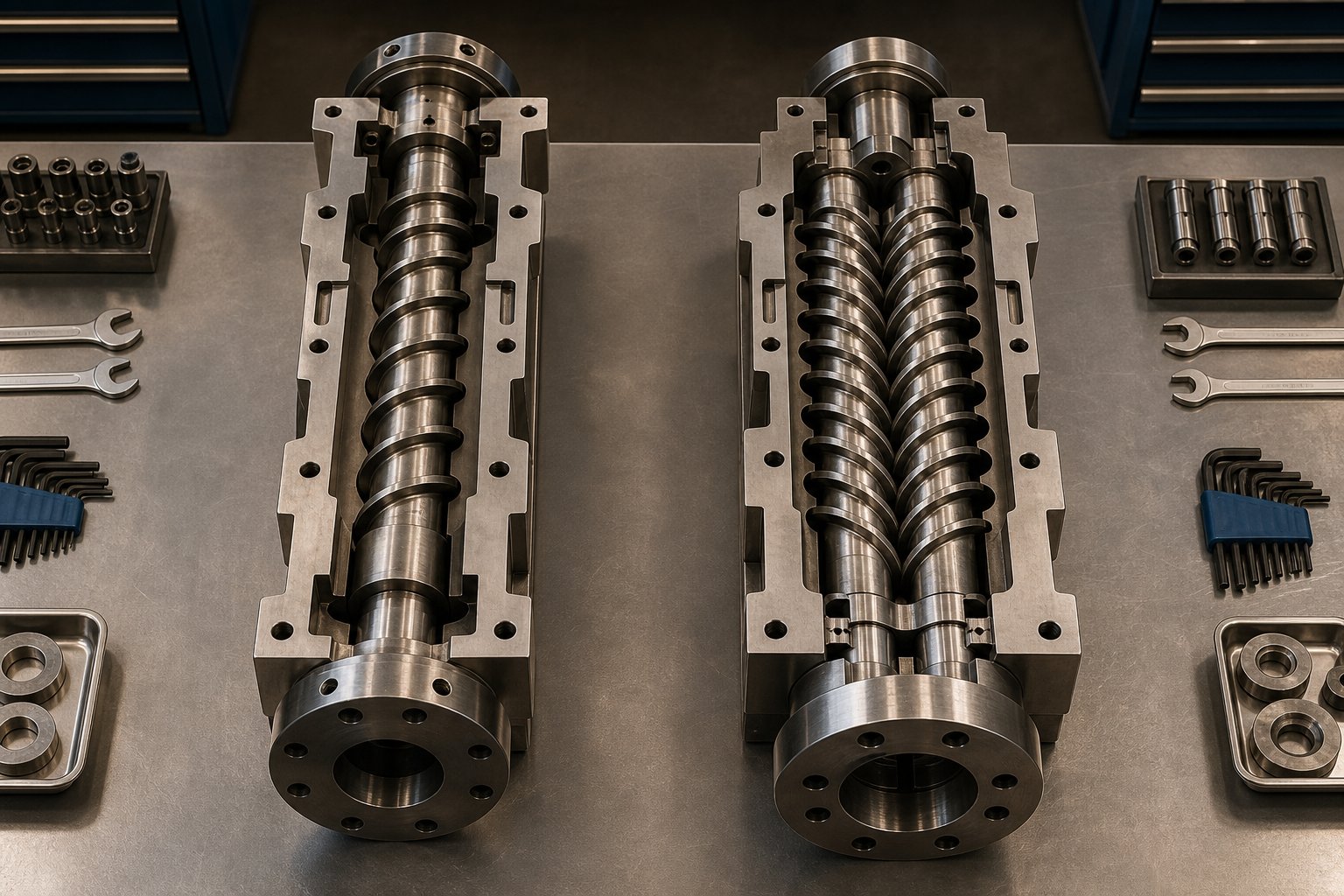
The polymer-to-screw matching guide above assumes you have already settled on a single screw platform. But that assumption itself deserves scrutiny. Twin screw extrusion handles some of the same polymers — and in certain applications, handles them far better. Conversely, a single extruder screw outperforms twin screw systems in scenarios where simplicity, energy efficiency, and steady-state throughput matter most. The deciding factor is not which technology is "better" in the abstract — it is which one fits the job. To make that call with confidence, you need to understand the fundamental mechanical difference that separates the two architectures and how it cascades into every performance criterion that matters on the production floor.
Operating Principles — Drag Flow vs. Positive Displacement
A single screw extruder moves polymer forward through drag flow. The barrel wall, stationary relative to the rotating screw, exerts frictional force on the polymer — and later viscous drag on the melt — pulling it along the helical channel toward the die. This mechanism works well with consistent, free-flowing pellet feedstocks and pre-compounded resins, but it is inherently sensitive to changes in material friction and melt viscosity. If the polymer slips against the barrel or the melt becomes too thin, conveying efficiency drops.
A co-rotating intermeshing twin screw extruder operates on a fundamentally different principle — one much closer to positive displacement. As Technovel's extrusion engineering resources explain, the two intermeshing screws create a series of enclosed chambers that physically push material forward, similar to a gear pump. The wiping action between screws prevents material from simply co-rotating with the shaft, ensuring consistent forward conveyance regardless of the polymer's friction characteristics or viscosity state.
This single distinction — drag flow versus positive displacement — is the root cause of nearly every performance difference between the two systems. It explains why twin screw extruders handle powders and irregular feedstocks more reliably, why they deliver narrower residence time distributions, why they offer superior mixing, and why they self-clean. It also explains why they cost more, consume more energy for simple tasks, and demand greater process expertise from operators.
Counter-rotating twin screw designs — sometimes called a double screw extruder configuration — take positive displacement even further. The opposing rotation creates a calendering effect that forcibly drives material forward with minimal dependence on friction. These systems are particularly common in PVC pipe and profile extrusion, where low-shear, high-stability conveying is essential to avoid thermal degradation.
Performance Comparison Across Technical Criteria
Surface-level comparisons often reduce this topic to "twin screw mixes better, single screw costs less." That framing misses critical nuances. The table below compares the two architectures across the full range of technical criteria that influence equipment selection — from mixing and shear characteristics to feed flexibility and maintenance burden.
| Criterion | Single Screw Extruder | Twin Screw Extruder (Co-Rotating Intermeshing) |
|---|---|---|
| Distributive Mixing | Limited — requires add-on mixing elements (pin, pineapple) for adequate blending | Excellent — intermeshing screws continuously exchange and reorient material between channels |
| Dispersive Mixing | Minimal without Maddock or barrier sections; cannot match twin screw intensity | Superior — kneading blocks generate intense shear to break agglomerates and achieve fine dispersion |
| Shear Rate Range | Moderate — controlled mainly by metering depth and screw speed | Wide and adjustable — modular screw elements allow shear to be tuned zone by zone |
| Residence Time Distribution | Broad — some material parcels experience significantly longer barrel exposure than others | Narrow — positive displacement and self-wiping ensure more uniform thermal history |
| Self-Cleaning Capability | None — material can stagnate in channel corners, especially at low screw speeds | High — intermeshing wiping action scrapes material from screw surfaces, reducing degradation risk |
| Output per Unit Energy (Simple Extrusion) | Higher — simpler drive train and lower torque demand yield lower specific energy for commodity resins | Lower — additional mechanical losses from two-screw bearings, gearbox, and intermeshing geometry |
| Capital Cost | Significantly lower — roughly 40-60% less than a comparable-bore twin screw system | Higher — complex gearbox, modular screw elements, and tighter manufacturing tolerances increase cost |
| Maintenance Complexity | Low — single screw, single bearing assembly, straightforward wear monitoring | Higher — modular element inspection, dual bearing systems, gearbox oil analysis, tighter clearance tolerances |
| Suitability for Pre-Compounded Resins | Excellent — designed for steady-state processing of homogeneous pellets | Capable but often over-engineered for this task |
| Suitability for Compounding and Reactive Processing | Poor — insufficient mixing intensity and residence time control | Excellent — the standard platform for masterbatch, filled compounds, reactive extrusion, and polymer blends |
| Typical Applications | Pipe, profile, film, sheet, wire coating, simple pelletizing | Compounding, masterbatch, reactive extrusion, devolatilization, advanced recycling |
| Feed Flexibility (Powder, Pellet, Liquid) | Best with uniform pellets; powders and irregular feedstocks cause bridging and inconsistent conveying | Handles pellets, powders, flakes, fibers, and liquid injection reliably via positive displacement feeding |
A few points in this comparison deserve emphasis. Energy efficiency favors the single screw system only when the application is straightforward — running pre-compounded HDPE into pipe, for example. As Wanplas engineering data illustrates, twin screw extruders can actually prove more energy-efficient for complex formulations because they achieve the required mixing in a single pass, whereas a single screw system might need multiple passes or external mixing equipment to reach the same quality threshold. Similarly, the capital cost gap narrows — or reverses — on a total-cost-of-ownership basis when the twin screw platform eliminates the need to purchase pre-compounded material at premium pricing.
The maintenance picture also carries nuance. Twin screw extruders have more components to monitor, but their modular screw design means you can replace individual worn elements in a specific zone without pulling the entire screw. A single screw showing wear in the metering section requires a full screw replacement or rebuilding — a distinction that affects both downtime planning and long-term spare-parts budgeting.
When Each System Excels
Single screw extruders dominate in applications where the polymer arrives ready to process — pre-compounded, consistently pelletized, and thermally stable. Pipe extrusion, blown and cast film, sheet production, wire and cable coating, and simple pelletizing all favor the single screw platform because these processes prioritize high-volume, steady-state throughput at the lowest possible cost per kilogram. The resin is already homogeneous; the screw's primary job is to melt it uniformly and pump it at stable pressure.
A parallel twin screw extruder steps in when the process itself demands transformation — blending multiple ingredients, dispersing pigments or fillers at high concentrations, removing volatiles under vacuum, or running reactive chemistry inside the barrel. Twin screw extruders are the standard for compounding lines, masterbatch production, devolatilization of hygroscopic or recycled feedstocks, and any formulation where the material's final properties are created during extrusion rather than before it. Their modular screw configurations let processors reconfigure mixing intensity, residence time, and shear profile for each new formulation — a flexibility that a fixed single-screw geometry simply cannot offer.
The recycling sector highlights both strengths clearly. Clean, sorted post-industrial regrind — uniform flake from a single resin — processes well on a single screw extrusion line with a vented two-stage design. Mixed post-consumer waste with variable contamination and multiple polymer fractions calls for the intensive mixing, devolatilization, and feed flexibility that only twin screw extruders provide.
The choice between single screw and twin screw extrusion is application-driven, not technology-driven. Neither system is inherently superior — each excels where its operating principle best matches the material, the formulation complexity, and the production economics of the job.
Understanding where your application falls on this spectrum is essential. But regardless of which platform you choose, the screw and barrel will eventually wear — and the rate, pattern, and severity of that wear depend on decisions made long before the first pellet drops into the hopper. Material selection, surface treatments, and wear monitoring strategies determine how long your screw maintains the tight tolerances that keep output consistent and energy costs under control.
Screw Materials, Coatings, and Wear Resistance
A perfectly designed screw geometry means nothing if the metal cannot survive the environment inside the barrel. From the moment rotation begins, the screw is under attack — ground down by hard filler particles, eaten away by corrosive off-gases, or scored by direct metal-to-metal contact. These wear mechanisms increase the clearance between the flight tips and the barrel wall, and that growing gap erodes everything the screw was designed to deliver: pumping efficiency, melt uniformity, and energy performance. Understanding what causes wear — and choosing materials that resist it — is what separates a screw that runs for years from one that fails in months.
Understanding Wear Mechanisms in Single Screw Extrusion
Wear inside a single extruder screw is not a single phenomenon. Three distinct mechanisms attack the screw and barrel surfaces, often simultaneously, and each one demands a different material response.
Abrasive wear is the most common form of degradation in plastics processing. It occurs when hard particles in the polymer stream — glass fibers, mineral fillers like calcium carbonate and talc, TiO2 pigments, or even contaminants in regrind — grind against the screw flights and barrel wall with each revolution. As Glycon Corp.'s Jeff Kuhman explains, hard materials tend to remove material from softer surfaces, which is why flight lands are typically hardfaced with abrasion-resistant alloys. The damage concentrates where unmelted solids press hardest — the trailing edge of the flight lands and the screw root in the feed and early compression zones. Some of the most aggressive fillers can reduce useful screw life by 50 percent or more if the metallurgy is not matched to the compound.
Corrosive wear is the gradual chemical destruction of metal surfaces. It strikes hardest when processing PVC, which releases hydrochloric acid (HCl) as it degrades, and fluoropolymers, which can produce hydrofluoric acid — one of the most aggressive chemical agents that metal surfaces encounter in any industrial process. Flame-retardant additives, certain stabilizers, and acetal resins also generate corrosive byproducts. As HAISI extrusion engineering resources detail, standard barrels and screws made of nitrided steel, tool steel, or alloy steel are vulnerable to acid attack and can deteriorate rapidly under these conditions. The corrosion oxidizes metal across the entire surface, weakening it structurally and making it far more vulnerable to mechanical wear — the two mechanisms feed each other in a destructive cycle.
Adhesive wear occurs when the screw flight lands physically contact the barrel wall. Under the high pressures and temperatures inside the barrel, those brief contact points momentarily weld together and then fracture — ripping metal from one or both surfaces. You will typically see evidence of adhesive wear as a burr or "rolling over" of the trailing edge of the flight land, or as scoring and galling on the barrel's inner surface. Common triggers include poor machine alignment, screw deflection caused by unbalanced pressure in the channel, or a phenomenon called solids wedging — where unmelted material plugs the channel and forces the screw sideways against the barrel. Extrusion experts Mark Spalding and Timothy Womer note that barrel alignment is critical for preventing this type of wear, especially on large-diameter and long extruders, and should be checked whenever a barrel is removed or changed.
Regardless of which mechanism dominates, the practical result is the same: flight clearance increases. That widening gap allows melt to leak backward over the flights instead of being pumped forward, reducing specific output rate and forcing operators to increase screw speed to compensate. The higher speed generates more shear heat, raises discharge temperature, and accelerates the wear cycle further — a pattern of diminishing returns that often goes unnoticed until product quality or production rate drops to unacceptable levels.
Screw and Barrel Material Options
Selecting the right material for your screw and barrel is not about picking the hardest or most expensive option — it is about matching the protection level to the specific wear mechanism your process creates. Think of it as a hierarchy, where each step up adds cost but also adds service life under increasingly aggressive conditions.
- Nitrided steel (entry-level protection) — The baseline for unfilled, non-corrosive polymers like general-purpose polyethylene or polypropylene. Gas nitriding hardens the surface layer of the screw, improving resistance to mild abrasive wear. It is cost-effective and adequate for many standard extrusion tasks, but the hardened case is relatively thin and offers little defense against corrosive compounds or highly filled resins.
- Hardfaced screw flights with bimetallic barrel liners (mid-range protection) — For moderately filled compounds or applications where moderate abrasion shortens nitrided screw life, hardfacing the flight lands with wear-resistant alloys dramatically extends service intervals. The barrel side benefits from a bimetallic liner — a centrifugally cast wear-resistant alloy bonded to the inside of a structural steel outer shell. Today's bimetallic barrels use alloys with high tungsten carbide content to deliver long wear life, and it is important to specify a screw hardfacing material that runs compatibly with the barrel lining to avoid adhesive wear between the two surfaces.
- Corrosion-resistant alloys and nickel-based coatings (for PVC, fluoropolymers, and corrosive additives) — Standard iron-matrix metals cannot survive prolonged acid exposure. Nickel-rich boron alloy barrel liners with molybdenum and carbide bases provide excellent acid resistance for corrosive resin processing. On the screw side, coatings such as Colmonoy 56 or Colmonoy 83 alloys protect against both light corrosion and mechanical wear. For the most aggressive fluoropolymer applications, fully corrosion-resistant construction — both screw and barrel — is necessary.
- Fully bimetallic or specialty-alloy construction (for severe abrasion) — When processing glass-fiber-reinforced compounds at high filler loadings, or running highly abrasive mineral-filled masterbatches, even standard hardfacing may not last. Fully encapsulated screw roots, tungsten-carbide-encased flight surfaces, and premium bimetallic barrel liners with the highest carbide content represent the top tier of wear protection. These components cost significantly more upfront but can last several times longer than mid-range options in severe service.
- Thermal-expansion-matched material pairs (for high-temperature resins) — Processing resins at elevated temperatures introduces another risk: if the screw and barrel have mismatched coefficients of thermal expansion (CTE), the clearance between them can shrink unpredictably, leading to metal-to-metal contact and seizure. Selecting materials with similar CTEs and maintaining precision gap control — typically around one-thousandth of the bore diameter per side — prevents this costly failure mode.
One point that catches many processors: alloys with lower tungsten carbide content may be easier to apply and machine, but they offer less wear resistance and have a greater tendency to gall when paired with the hardest barrel linings. Specifying the screw in isolation from the barrel is a mistake — the two must be considered as a matched system, with compatible hardness levels and metallurgical properties.
Wear Monitoring and Replacement Planning
Even the best material selection does not stop wear entirely — it slows it. Every screw extruder will eventually reach a point where accumulated wear degrades performance enough to affect the bottom line. The difference between reactive maintenance and planned replacement lies in how you monitor that progression.
The most direct measurement is flight-to-barrel clearance. When new, this clearance is minimal — typically the nominal screw diameter divided by 1,000 per side. For a 3.5-inch extruder, that means roughly 0.004 inches of clearance per side. As Spalding and Womer document, once that clearance increases substantially, extruder performance drops measurably. In their example of a 100-mm screw running polyethylene, maintaining constant output as wear progressed required progressively higher screw speeds and produced increasingly elevated discharge temperatures — eventually reaching a point where the line could not hold quality at its target rate.
Common replacement guidelines include changing the screw when flight clearance reaches four times its original value, or when the hardfacing is completely worn through. But the most economical approach is tracking process performance indicators and replacing parts when the cost of degraded output exceeds the cost of the new screw. Key indicators to track include:
- Specific rate decline — output (lb/hr or kg/hr) divided by screw speed. A dropping specific rate signals that more leakage is occurring over worn flights.
- Rising discharge temperature — as operators increase screw speed to compensate for output loss, viscous dissipation adds heat. Higher melt temperature may push the process outside its quality window.
- Increasing specific energy consumption — more motor energy per kilogram of output means the screw is working harder to move less material forward.
- Product quality drift — gauge variation, surface defects, or color inconsistency that worsens gradually over weeks or months, often before operators consciously notice the shift.
Spalding and Womer also offer a practical caution: a screw should never be refurbished more than three times. Each weld-on hardfacing cycle deteriorates the base metal, increasing the risk of delamination — where the hardfacing layer cracks and breaks loose, creating loose hard particles that can damage both the screw and barrel as they travel downstream.
A spare screw kept in inventory allows a changeover without extended line downtime. When the current screw reaches its replacement threshold, the spare goes in immediately, and the worn screw can be evaluated for rebuilding or replaced entirely. This approach transforms maintenance from a reactive disruption into a planned event — protecting both uptime and product quality.
Total cost of ownership is the real metric here. A properly specified screw — built from the right alloy, with the right surface treatment, for the right compound — lasts significantly longer, holds tighter tolerances throughout its service life, and reduces the cumulative cost of downtime, replacement, and scrap. When sourcing custom or replacement single screw barrel assemblies, working with a manufacturer like NANHAIYA that builds to specific machine models, drawings, samples, or measured dimensions ensures proper material specification and fit for the application's wear profile — whether you are running pipe, film, sheet, pelletizing, or recycling lines. Providing exact dimensional data upfront allows the manufacturer to specify the correct metallurgy, hardfacing, and barrel liner combination for your compound, rather than defaulting to a generic solution that may underperform in service.
Material selection and wear management keep the screw performing as designed. But even a screw in perfect mechanical condition can produce defective product if its geometry does not match the process — and diagnosing whether the root cause is wear, design, or operating conditions requires a structured troubleshooting approach.
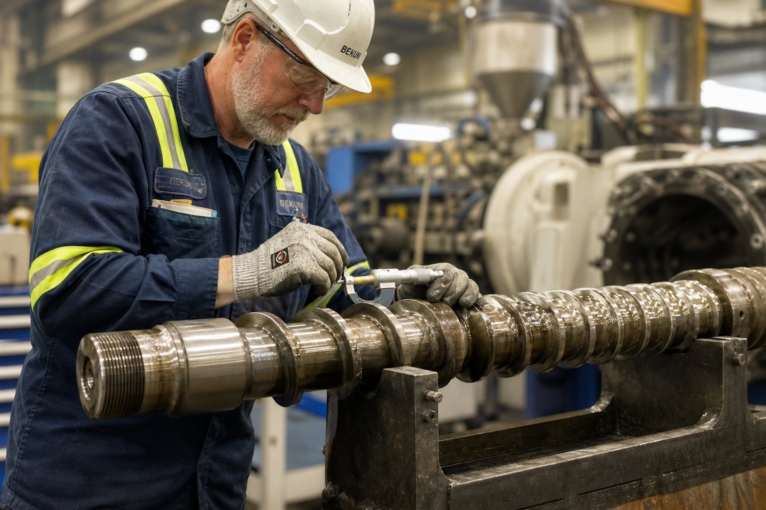
Troubleshooting Common Single Screw Extrusion Problems
A screw in perfect mechanical condition can still produce bad product — and a worn screw can sometimes mask the real problem. When output starts surging, surfaces go rough, or melt temperature climbs beyond the target window, the instinct is often to adjust barrel temperatures or tweak screw speed. Those moves may suppress the symptom temporarily, but if the root cause sits in the extrusion screw design itself, no process adjustment will fix it permanently. Effective single screw extruder troubleshooting requires connecting visible symptoms to the screw geometry decisions that created them — and knowing which design modification actually resolves the issue.
Surging and Output Instability
Surging — the cyclic oscillation of discharge pressure, motor current, and output rate while all set points remain constant — is arguably the most disruptive problem on any extrusion line. It shows up as gauge bands in film, wall-thickness variation in pipe, and weight fluctuations in pelletizing. The line might run acceptably for hours, then suddenly begin cycling every few minutes as if the screw has a heartbeat of its own.
The most common screw-related cause is solid-bed breakup in the compression zone. When the compression ratio is too high or the taper too aggressive, the shrinking channel crushes the solid bed unevenly, fracturing chunks of unmelted polymer away from the compacted mass. These fragments drift into the melt pool and temporarily block forward flow, causing pressure to spike and then collapse as the fragment melts. The cycle repeats as long as the solid bed keeps fracturing.
A barrier screw design directly addresses this failure mode. By physically separating solids from melt with a secondary flight, the barrier geometry prevents broken solid fragments from disrupting the melt channel. Alternatively, lengthening the compression zone — spreading the same compression ratio over more screw turns — reduces the taper rate and applies a gentler, more uniform squeeze to the solid bed, lowering the risk of fracture.
Not every surge originates from screw geometry, though. As extrusion specialist Mark Spalding documents, the most frequent root cause in smooth-bore extruders is improper temperature in the solids conveying section. A feed casing that runs too hot — often because cooling water channels have occluded with mineral deposits — weakens the polymer's grip on the barrel wall, causing forwarding forces to fluctuate. Similarly, inadequate screw cooling can overheat the screw root, allowing pellets to stick and co-rotate instead of sliding forward. In one case Spalding describes, an 8-inch two-stage screw extruder experienced violent surging that was traced to a screw cooling hole that was three diameters too short — once extended to the end of the solids conveying section and paired with a dedicated water pump, the surging never returned.
Feed-related causes also deserve attention. Bridging in the hopper, inconsistent pellet or regrind bulk density, and starve-feeding that fails to keep the screw channel full can all produce cyclic output variation that mimics screw-design surging. Rule out these upstream factors before committing to a screw change.
Melt Fracture, Gels, and Poor Homogeneity
Melt fracture appears as a sharkskin or orange-peel texture on the extrudate surface. It results from excessive shear stress at the die entrance — the melt accelerates through the die lip faster than the polymer chains can relax, causing the surface layer to fracture and reform in a rough pattern. While die geometry plays a role, the screw contributes by delivering melt that is too cold, too viscous, or thermally non-uniform. A melt stream with hot and cold striations hits the die with widely varying local viscosities, and the coldest parcels experience the highest shear stress — enough to trigger surface fracture even when the average melt temperature looks acceptable.
Gels — those small, hard, translucent specks that ruin film clarity and weaken sheet products — are either unmelted polymer particles or crosslinked material that degraded in a stagnant corner of the screw channel. The two problems require different solutions: unmelts point to insufficient melting capacity, while crosslinked gels point to excessive residence time or dead spots in the screw design.
Adding a Maddock (fluted) mixing section at the screw tip addresses both melt fracture and unmelts simultaneously. The polymer must pass through a narrow clearance between the barrier land and the barrel wall, which subjects every particle to a minimum shear threshold — unmelted fragments are forced through intense shear that completes their melting, while the overall melt stream gets homogenized to a narrower temperature range. Extending the metering zone also helps by providing more screw turns for the recirculating melt to blend thermally before reaching the die. For gels caused by degradation, the fix is different: eliminate dead spots by polishing channel corners, reduce L/D or screw speed to shorten residence time, or switch to a streamlined mixing element that avoids stagnant pockets.
Excessive Shear Heating and Thermal Degradation
When the extrudate exits the die hotter than the barrel set points — sometimes substantially hotter — you are looking at viscous dissipation exceeding barrel cooling capacity. Every revolution of the screw converts mechanical energy into heat within the melt, and the rate of conversion depends on shear rate squared multiplied by melt viscosity. A metering zone that is too shallow creates a high shear rate in a thin channel, generating heat faster than the barrel heaters can extract it. Similarly, a compression ratio that is too aggressive for the polymer forces excessive work into the transition zone, raising the melt temperature before it even reaches metering.
As CEAD Group's extrusion engineering resources emphasize, excessive shear not only raises temperature but can damage the polymer's molecular structure itself — breaking chains, reducing molecular weight, and degrading mechanical properties in the finished product. The risk is particularly acute for heat-sensitive materials like PVC, PVDF, and certain bioplastics, where even a few degrees above the processing ceiling triggers irreversible degradation.
The screw design fix is straightforward in concept: increase metering channel depth to reduce shear rate, lengthen the compression zone to distribute melting work more gradually, or reduce the compression ratio to lower the total energy input during the transition. For processors who cannot replace the screw immediately, lowering screw speed reduces shear heating linearly — but it also reduces output, which is rarely an acceptable long-term trade-off. The permanent solution is an extrusion screw design matched to the polymer's viscosity and thermal limits.
| Symptom | Likely Screw-Related Cause | Recommended Screw Design Modification |
|---|---|---|
| Cyclic output surging (pressure oscillation at constant set points) | Solid-bed breakup from too-aggressive compression ratio or too-short compression zone | Switch to a barrier screw design; lengthen the compression zone; reduce compression taper rate |
| Sharkskin or melt fracture on extrudate surface | Non-uniform melt temperature delivering viscosity striations to the die | Add a Maddock mixing section; extend the metering zone for better thermal homogenization |
| Unmelted particles (gels from unmelt) in finished product | Insufficient melting capacity — metering zone too short, no mixing element, or solid-bed fragments bypassing compression zone | Install a barrier flight in the compression zone; add a dispersive (Maddock) mixer at the screw tip |
| Crosslinked or degraded gels (brown or amber specks) | Dead spots in screw channel allowing material to stagnate and overheat | Polish channel transitions; eliminate sharp corners; use streamlined mixing elements without stagnant pockets |
| Melt temperature exceeds set points by a large margin | Metering depth too shallow, generating excessive viscous dissipation | Increase metering channel depth; reduce compression ratio; lengthen the compression zone |
| Polymer degradation (discoloration, odor, brittleness) | Excessive shear heating or too-long residence time from overly high L/D or stagnant channel regions | Reduce L/D if possible; increase metering depth; eliminate dead spots; consider a shorter, more efficient screw geometry |
| Color streaking or poor additive dispersion | Lack of mixing capability in a standard three-zone screw | Add a distributive mixing element (pin mixer or pineapple section) for color; add a dispersive mixer for agglomerate breakup |
| Declining output at constant screw speed over weeks or months | Flight wear increasing clearance, allowing backward melt leakage over the flights | Measure flight-to-barrel clearance; replace or rebuild the screw with appropriate wear-resistant materials |
Notice a pattern across every row of this table: each symptom links back to a specific geometric or material characteristic of the screw. Temperature adjustments and speed changes may mask the problem temporarily, but lasting resolution requires matching the screw's design to the polymer and the process. That realization naturally raises a practical question — when you have identified the needed design change, how do you translate it into an actual screw specification that a manufacturer can build?
How to Specify or Replace a Single Extruder Screw
Every diagnostic fix in the troubleshooting table above ends the same way — with a screw design modification that someone has to translate into a real, buildable part. Yet this is exactly where many processors stall. You know the compression ratio needs to change, or that a barrier flight would solve the surging problem, but turning that insight into a purchase order that arrives as a correctly built screw requires a structured specification process. Skip steps here, and the replacement screw can introduce new problems as easily as it solves old ones.
Parameters to Define Before Specifying a Screw
Think of screw specification as a decision tree. Each input narrows the design space until you arrive at a geometry, material, and surface treatment combination that fits the job. Here is the workflow, roughly in order of priority:
- Identify the polymer type and grade. This single input drives compression ratio, shear sensitivity limits, and whether venting or corrosion-resistant metallurgy is needed. Running HDPE pipe resin? Expect a high compression ratio and possibly a barrier design. Processing rigid PVC powder? The screw demands a completely different philosophy — low compression, gentle taper, corrosion-resistant alloy. As covered in the polymer matching section, a screw designed for one resin family can be entirely wrong for another.
- Define the target output rate. Output determines whether a general-purpose three-zone geometry is adequate or whether a barrier screw with mixing elements is needed to melt cleanly at high throughput. It also influences metering depth — higher output targets push toward deeper metering channels, which increase drag flow capacity but reduce shear intensity.
- Specify product geometry and quality requirements. A thick-wall pipe tolerates minor melt-temperature non-uniformity that a thin blown film cannot. Optical clarity demands in film or sheet call for mixing elements that homogenize the melt beyond what a simple metering zone achieves. Your product specification sets the bar for how much mixing and thermal uniformity the screw must deliver.
- Document the extruder platform — make, model, barrel bore, and L/D. The screw must physically fit the machine. Bore diameter, shank configuration, drive spline or key details, and overall flighted length are non-negotiable mechanical constraints. Whether you are running a Milacron extruder, a Wenger single screw extruder for food-grade applications, or any other platform from the wide range of single screw extruder manufacturers worldwide, the screw's mechanical interface must match exactly. Even a fraction of a millimeter off on the root diameter or flight OD changes the critical flight-to-barrel clearance that governs pumping efficiency.
- Assess whether mixing or venting is needed. Color concentrates, additive masterbatches, or recycled feedstocks with contaminants often require dedicated mixing sections — dispersive, distributive, or both. Hygroscopic resins or regrind with volatile contamination may demand a two-stage vented design. These features add length, complexity, and cost, so they should be specified deliberately rather than defaulted.
- Determine wear-resistance requirements based on the compound. Unfilled polyolefins on a standard nitrided screw may last years. Glass-fiber-reinforced nylon on that same screw might chew through the flights in months. The filler type, loading percentage, and any corrosive byproducts from the resin or additives dictate the metallurgy and surface treatment — nitrided, hardfaced, bimetallic, or fully encapsulated — as discussed in the materials and coatings section.
Each parameter maps directly to a design decision covered earlier in this article. Polymer type sets the compression ratio and thermal constraints. Output rate sizes the metering depth and determines whether a barrier flight earns its cost. Product quality defines mixing requirements. Machine dimensions constrain the physical envelope. And compound abrasiveness or corrosiveness selects the metallurgy. When all six inputs are defined clearly, the screw design practically specifies itself.
The Screw Within the Full Extrusion Line
Here is a mistake that costs processors time and money more often than it should: treating the screw as an isolated component rather than one element in a tightly coupled system. The barrel temperature profile, die geometry, screen pack mesh and area, and downstream cooling all interact with screw performance — and changing one without accounting for the others can produce results that seem paradoxical.
Imagine upgrading from a general-purpose screw to a barrier design with a Maddock mixer. The new screw delivers a more uniform, hotter melt — exactly as intended. But the existing die was sized for the old screw's cooler, less uniform output. The higher melt temperature reduces viscosity, changing the pressure-flow balance across the die and potentially altering extrudate dimensions. Downstream cooling, calibrated for the old melt temperature, may no longer quench the product fast enough to hold dimensional tolerance. The screw upgrade was correct in isolation, but the system was not adjusted to match.
Barrel condition deserves particular attention. As established extrusion engineering references emphasize, a perfectly designed new screw installed in a worn barrel will not restore the flight-to-barrel clearance — and the melt leakage path remains open regardless of the screw's quality. The screw and barrel function as a matched pair, and both must be within tolerance for the system to pump efficiently. Measuring barrel bore diameter before ordering a replacement screw prevents the disappointment of discovering, after installation, that the new part cannot deliver its rated performance because the barrel has already worn beyond specification.
Screen packs and breaker plates also interact with screw output. A finer screen pack increases head pressure, which shifts the drag-flow-versus-pressure-flow balance in the metering zone. If the screw's metering depth was optimized for a lower head pressure, the added restriction reduces net output and increases melt residence time. Processors who change screen mesh size regularly — common when running recycled feedstocks with variable contamination — should specify a screw with metering geometry that tolerates a range of head pressures without excessive output sensitivity.
The takeaway is straightforward: specify the screw for the system it will operate in, not in a vacuum. Document barrel bore measurements, die pressure drop at target output, screen pack configuration, and downstream cooling capacity alongside the polymer and output parameters. A screw manufacturer who receives this complete picture can design a geometry that performs within the actual operating envelope — not just on paper.
Working With a Screw Manufacturer for Custom Solutions
Specifying the design is one half of the process. Communicating it to a manufacturer who can build it correctly is the other. In practice, replacement and upgrade screws are ordered through one of three pathways — and the information you provide determines how accurately the finished screw matches your needs.
The first pathway is ordering from a machine model number. If your extruder is a standard platform from a major OEM, an experienced screw manufacturer will have reference dimensions on file or can source them. You provide the machine make, model, serial number, and the polymer and output requirements, and the manufacturer matches the mechanical interface while optimizing the screw geometry for your specific application.
The second pathway is ordering from drawings. OEM drawings or detailed engineering sketches provide exact dimensions — root diameters, flight OD, pitch, zone lengths, mixing section geometry, shank details, and tolerances. This is the most precise method and eliminates ambiguity. If you have access to the original screw drawing, it should be the primary reference document.
The third pathway is ordering from a worn screw sample or measured dimensions. When no drawing exists — common with older machines or screws that have been rebuilt multiple times — the manufacturer reverse-engineers the geometry from the physical part. Sending the worn screw allows the factory to measure every dimension directly, compensate for wear, and reproduce the original design (or improve upon it based on your process feedback). Alternatively, you can take and submit detailed measurements yourself: flight OD at multiple points along the length, root diameters in each zone, overall flighted length, shank dimensions, and any mixing section details.
Whichever pathway you use, always communicate the compound being processed and any wear or performance issues you are trying to solve. A manufacturer who knows you are running 30% glass-filled nylon will specify a completely different metallurgy than one who assumes unfilled polyethylene — and the service life difference can be measured in years.
For processors seeking custom and replacement single screw barrel solutions, NANHAIYA offers manufacturing to specific machine models, drawings, samples, or measured dimensions — serving pipe, film, sheet, pelletizing, and recycling lines. Providing your exact specifications upfront allows them to match the metallurgy, geometry, and surface treatment to your application rather than shipping a generic part that may underperform from day one.
Ultimately, the single extruder screw is not a commodity — it is a precision processing tool whose performance depends on every decision covered in this article: zone design, geometry parameters, design variant selection, polymer matching, material and coating specification, and system-level integration. Processors who treat screw specification with the same rigor they apply to die design or resin selection consistently achieve higher output, lower scrap, and longer service life. The knowledge to make those decisions is already in your hands. The next step is applying it to the screw turning inside your barrel right now.
Frequently Asked Questions About Single Extruder Screws
1. What are the three zones of a single extruder screw and what does each do?
A single extruder screw is divided into three functional zones. The feed zone uses deep, constant-depth flights to intake solid pellets or flakes and convey them forward using frictional drag against the barrel wall. The compression (transition) zone progressively reduces channel depth to compact the solid bed against the heated barrel, melting the polymer through conducted heat and viscous shear energy. The metering zone features a shallow, constant-depth channel that homogenizes the melt temperature and generates the pressure needed to push molten polymer through the screen pack and die. Each zone must be correctly sized for the specific polymer being processed — a mismatch in any zone leads to defects like surging, unmelts, or thermal degradation.
2. How do I choose the right compression ratio for my polymer?
Compression ratio — feed-zone channel depth divided by metering-zone channel depth — must match the density change a polymer undergoes when transitioning from solid to melt. Semi-crystalline resins like HDPE and polypropylene experience a large volume reduction upon melting, so they typically need higher compression ratios in the 3.0:1 to 4.0:1 range. Amorphous resins like polystyrene and ABS change density very little and work best with lower ratios around 2.5:1 to 3.0:1. PVC requires the gentlest treatment, with ratios as low as 1.5:1 to 2.5:1 to prevent shear-induced degradation. Filled compounds also need adjusted ratios because the non-melting filler reduces the compressible fraction. Choosing the wrong compression ratio is one of the most common causes of poor melt quality in single-screw extrusion.
3. What is the difference between a single screw extruder and a twin screw extruder?
The fundamental difference is the conveying mechanism. A single screw extruder relies on drag flow — friction and viscous forces between the polymer, barrel wall, and screw surface push material forward. A co-rotating intermeshing twin screw extruder operates closer to positive displacement, with interlocking screws creating enclosed chambers that physically push material forward regardless of friction. This distinction drives all performance differences: twin screws offer superior mixing, self-cleaning capability, narrower residence time distribution, and better feed flexibility for powders and liquids. Single screw systems counter with lower capital cost, simpler maintenance, and higher energy efficiency for straightforward processing of pre-compounded pellets. Single screws dominate in pipe, film, and sheet extrusion, while twin screws excel in compounding, reactive extrusion, and devolatilization.
4. What causes surging in a single screw extruder and how can it be fixed?
Surging — cyclic oscillation of pressure and output at constant set points — most commonly results from solid-bed breakup in the compression zone. When the compression ratio is too aggressive or the taper too short, the solid bed fractures, sending unmelted chunks into the melt stream that temporarily block forward flow. Switching to a barrier screw design physically separates solids from melt and prevents this breakup. Lengthening the compression zone to apply a gentler taper also helps. However, not all surging is screw-related: improper feed-section cooling, occluded cooling channels, inconsistent feedstock bulk density, and hopper bridging can produce similar symptoms. Ruling out these upstream factors before committing to a screw redesign saves time and cost. For custom replacement screws built to solve specific surging issues, manufacturers like NANHAIYA can work from machine models, drawings, or worn screw samples.
5. How do I know when a single extruder screw needs to be replaced?
Monitor four key performance indicators over time. First, track specific rate — output divided by screw speed — as a declining value signals increased melt leakage over worn flights. Second, watch for rising discharge temperature at constant set points, indicating operators are compensating for lost output by running higher speeds that generate more shear heat. Third, note increasing specific energy consumption per kilogram of output. Fourth, look for gradual product quality drift such as worsening gauge variation or surface defects. Physically, measure flight-to-barrel clearance periodically and plan replacement when clearance reaches roughly four times its original new-screw value. A spare screw kept in inventory allows planned changeovers without extended downtime, transforming maintenance from reactive to proactive.
Written by
Nanhaiya Technical Team
Zhoushan Nanhaiya Plastic Machinery Co., Ltd.
The Nanhaiya technical team supports screw and barrel manufacturing projects through application review, technical communication, custom manufacturing coordination, and production and quality control.
Discuss Your Application
Related Articles
More insights on screw barrel technology and plastics processing.

What Nobody Tells You About Screw Barrel For Plastic Machine Design
Oct 10, 2026
Learn how screw barrel for plastic machine design affects melt quality, throughput, and wear life. Covers geometry, resin matching, troubleshooting, and sourcing.
Read Article
Single Screw Extruder for Sheet: Stop Guessing, Start Specifying
Oct 9, 2026
Learn how to specify a single screw extruder for sheet production. Covers screw geometry, resin-specific processing, troubleshooting, and maintenance best practices.
Read Article
PE Pipe Extruder Machine: What Datasheets Won't Tell You
Oct 9, 2026
Learn how a PE pipe extruder machine works, key specs explained, material grade selection, maintenance tips, and buyer guidance beyond the datasheet.
Read ArticleLooking for something else?
Search by material, symptom or product and jump straight to the relevant page.
These are navigation suggestions based on keyword matching — not a quotation, not a delivery commitment, and not a substitute for engineering review. Final specification is confirmed by our engineers against your drawings and processed material.
Need help with screw barrel selection?
Share your machine model, processed material and application. Our team can help with pricing and technical support.