

What Every Engineer Should Know About Screw Extruders
Choosing the wrong extruder architecture can quietly drain thousands in wasted energy, excess scrap, and unnecessary downtime. Yet the decision between a single and twin screw extruder is often based on habit or hearsay rather than engineering fundamentals. This guide exists to change that.
What Is a Screw Extruder and Why Does It Matter
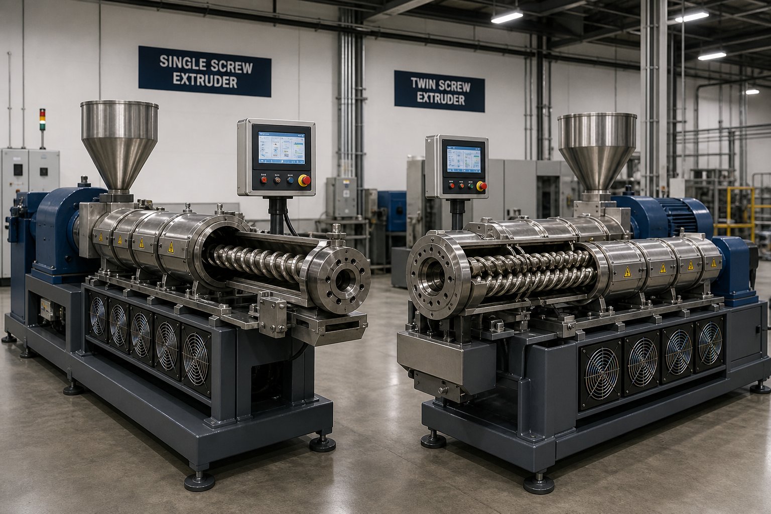
A screw extruder is a continuous processing machine that uses one or more rotating screws inside a heated barrel to melt, mix, and push material through a shaped die. Raw thermoplastic pellets, powders, or other feedstocks enter one end, and a fully formed product emerges from the other. It is the backbone of modern polymer manufacturing, supporting everything from packaging film to medical tubing.
The critical distinction comes down to how many screws sit inside that barrel. A single screw extruder relies on one rotating screw and depends heavily on friction-driven drag flow to move material forward. A twin screw extruder uses two intermeshing screws that mechanically push material through the barrel using positive displacement. That difference in conveying mechanism changes virtually everything about how the machine melts, mixes, and pressurizes your material.
When engineers evaluate an extruder twin screw configuration against a single screw alternative, they are really asking a deeper question: does my process need the material to do the work, or do I need the machine to do the work?
Who This Guide Is For
This article is written for process engineers evaluating new extrusion lines, plant managers weighing upgrade investments, and equipment buyers who need a clear technical framework before requesting quotes. You will not find vague marketing claims here. Instead, expect detailed engineering comparisons, practical decision tools, and myth-busting analysis grounded in real processing science.
The single biggest decision factor between extruder types is the conveying mechanism: drag flow versus positive displacement. Every difference in mixing, throughput, cost, and application suitability traces back to this fundamental distinction.
The mechanics behind that distinction, and why it matters for your specific process, start with understanding exactly how each screw extruder converts raw material into a finished melt.
Working Principles Behind Single and Twin Screw Extrusion
Every extrusion process begins the same way: raw material enters a barrel, meets a rotating screw, and eventually exits as a uniform melt. But what happens between those two endpoints is radically different depending on whether one screw or two is doing the work. Understanding these mechanics is not academic trivia. It directly determines your melt quality, mixing uniformity, and process flexibility.
How a Single Screw Extruder Works
Imagine dragging your hand across a table with a layer of honey between your palm and the surface. The honey moves forward because of friction between two surfaces. That is essentially how single screw extrusion works, a principle engineers call drag-flow conveying.
Inside a single screw extruder, material is pushed forward by the frictional difference between the polymer and the barrel wall versus the polymer and the screw surface. The barrel needs to "grip" the material more than the screw does. If friction against the barrel wall is too low, the material simply rotates with the screw and goes nowhere. This makes single screw performance inherently dependent on the polymer's rheology, its frictional characteristics, and its melt behavior.
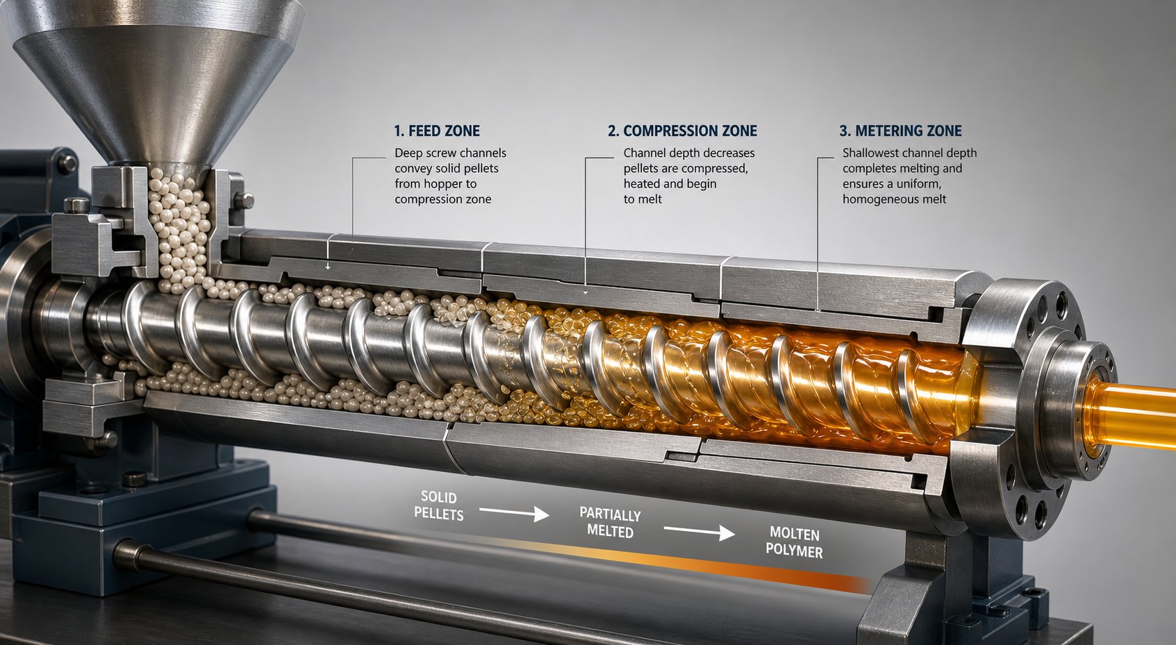
The screw itself is divided into three classical zones:
- Feed zone: Deep screw channels accept solid pellets or powder from the hopper and begin moving them forward through frictional drag.
- Compression (transition) zone: The channel depth gradually decreases, compacting the material and squeezing out trapped air. Melting accelerates here as the polymer is pressed against the hot barrel wall, generating intense viscous shear heating.
- Metering zone: A shallow, constant-depth channel delivers a uniform, fully melted stream to the die at consistent pressure and flow rate.
Melting in a single screw system occurs primarily through a thin film of molten polymer at the barrel wall. As the screw rotates, it scrapes this melt film and forces it into a circulating pool, gradually consuming the remaining solid bed. This mechanism means the material itself is responsible for generating most of the pressure and mixing energy. Change the polymer, and you often need to change the screw design to match.
How a Twin Screw Extruder Works
Twin screw extrusion takes a fundamentally different approach. Instead of relying on the material's frictional properties, intermeshing twin screw designs use positive displacement conveying. The two screws interlock, forming closed or semi-closed pockets that mechanically push material forward with each rotation, regardless of how slippery or inconsistent the feedstock might be.
This positive displacement principle means that a specific volume of material advances with every turn of the screws, making throughput far less sensitive to changes in bulk density, particle shape, or melt viscosity. As one technical overview explains, intermeshing twin screw extruders form closed or semi-closed cavities that enable this positive displacement, and the degree of conveying control depends on how tightly the screws mesh together.
Twin screw configurations split into two major categories:
- Co-rotating: Both screws turn in the same direction. Material follows a figure-eight path as it transfers from one screw to the other, experiencing high shear and excellent distributive mixing. Self-wiping geometry prevents dead spots and keeps residence time tight. Co-rotating designs dominate compounding and reactive extrusion.
- Counter-rotating: The screws turn in opposite directions, creating a calendering effect in the nip region where the screws meet. This generates high pressure with comparatively lower shear, making it well-suited for applications like PVC profile extrusion that demand gentle processing and strong pressure buildup.
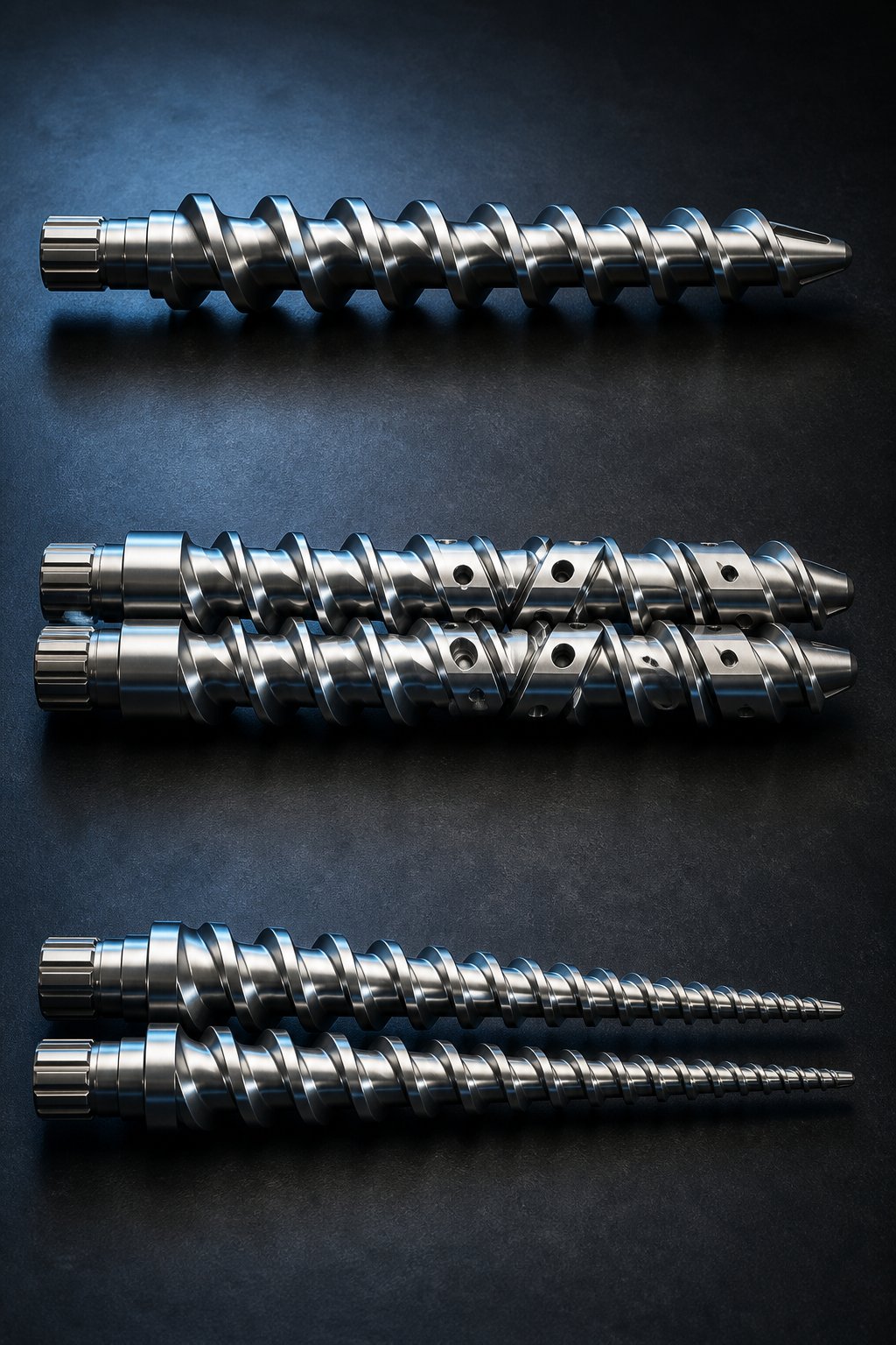
Here is where twin screw design gets especially powerful: modular screw element architecture. Rather than machining a single fixed screw, engineers assemble individual conveying elements, kneading blocks, and mixing discs onto a splined shaft. Want more shear in a particular zone? Swap in aggressive kneading blocks. Need gentler conveying downstream? Use wide-pitch transport elements. This modularity lets you reconfigure the screw profile for different formulations without buying a new screw.
Why the Conveying Mechanism Changes Everything
The drag-flow versus positive displacement distinction might sound like a textbook detail, but it cascades into every performance metric that matters on the plant floor.
In screw extrusion driven by drag flow, throughput, mixing, and pressure generation are all coupled. You cannot change one without affecting the others, because they all depend on the same frictional interaction between polymer, screw, and barrel. Increase screw speed to boost output, and you simultaneously raise shear heating, potentially degrading heat-sensitive materials. Switch to a different resin grade, and your carefully optimized process window may shift unpredictably.
Positive displacement in twin screw systems decouples these variables. Throughput is primarily controlled by the feeder rather than screw speed, giving engineers independent control over residence time, shear intensity, and output rate. You can run the screws faster for more mixing without being forced into higher throughput, or slow them down for gentler processing without starving the die.
This independence also explains why twin screw extrusion handles difficult materials, powders, recycled flake, and multi-component formulations, with far greater consistency. The machine does the conveying work, so unpredictable material behavior does not derail the process.
Drag-flow systems make the material responsible for its own transport. Positive displacement systems make the machine responsible. That single engineering distinction drives every meaningful difference in mixing capability, residence time control, and process flexibility between single and twin screw extruders.
Of course, knowing how each machine moves material is only half the picture. The physical dimensions of the screw, its length-to-diameter ratio, flight depth, and compression geometry, determine how effectively that conveying mechanism translates into real-world melting and mixing performance.
Screw Geometry and Design Parameters That Drive Performance
The conveying mechanism gets material moving, but the physical dimensions of the extruder screw determine how well that movement translates into a quality melt. Think of it this way: drag flow versus positive displacement tells you how the machine works, but length-to-diameter ratio, flight depth, and compression geometry tell you how well it works for your specific application. These parameters are where screw extruders diverge most sharply in capability, and where poorly matched specifications quietly cost manufacturers thousands in scrap, energy waste, and unnecessary downtime.
L/D Ratio and Its Impact on Processing
The length-to-diameter ratio, expressed as a number followed by ":1," is the primary sizing parameter for any extruder. It is calculated by dividing the effective flighted length of the screw by its outer diameter. A screw with a 1,500 mm working length and a 50 mm outer diameter has an L/D ratio of 30:1.
Why does this ratio get so much attention? Because L/D effectively sets the residence time of the polymer inside the barrel at a given screw speed, and residence time controls nearly everything that happens to the melt: heat absorption, viscosity development, mixing quality, devolatilization, and any chemical reactions in the case of reactive extrusion. A 24:1 barrel and a 36:1 barrel running at the same screw speed will produce dramatically different melt quality from the same resin.
L/D also determines how much screw real estate is available for functional zones, including feeding, compression, metering, mixing, and venting. A short barrel forces you to compress those functions into less space, while a longer barrel lets you stage them deliberately.
Here is where the two extruder types diverge significantly:
- Single screw extruders typically range from 24:1 to 36:1, with the bulk of commodity machines falling in the 24:1 to 32:1 band. Beyond roughly 36:1, screw deflection and shaft stress become significant design constraints, which is why single extruder screw L/D rarely exceeds 40:1 in production machines.
- Co-rotating twin screw extruders routinely run 36:1 to 48:1, with high-performance compounding machines pushing 56:1 to 60:1 and beyond. The modular element-on-splined-shaft architecture handles longer lengths far more easily than a single continuous machined screw.
- Counter-rotating twin screw extruders, used almost exclusively for PVC, run shorter L/D ratios of 18:1 to 24:1. Their positive-displacement pumping action does not benefit from extra length, and keeping residence time short is essential for PVC heat stability.
A useful rule of thumb from experienced engineers: add L/D only where you can specify a function for the additional length. If you cannot describe what the extra four diameters between a 28:1 and a 32:1 specification will actually do in your process, the additional cost is unjustified.
Flight Depth and Compression Ratio
Channel depth is the radial distance from the flight tip down to the screw root, and it defines the space where material actually resides and flows. For twin screw and barrel assemblies, channel depth is calculated directly from the outer diameter (Do) and inner root diameter (Di):
H = (Do - Di) / 2
Deeper channels provide higher free volume per unit length, allowing greater throughput capacity. But they also reduce the shear rate imposed on the material, since shear rate is inversely proportional to channel depth. This is a critical trade-off: double the channel depth, and you halve the shear rate at the same screw speed.
The compression ratio quantifies how much the available volume decreases from the feed section to the metering section. It is calculated as:
CR = Hfeed / Hmetering
A compression ratio of 3:1 means the feed zone channel is three times deeper than the metering zone. This progressive volume reduction compacts the material, squeezes out trapped air, and drives melting efficiency. Sounds straightforward? The complication is that single screw designs are far more constrained by compression ratio selection than twin screw configurations. Because a single extruder screw relies entirely on drag flow, the compression ratio must be carefully matched to the specific polymer's bulk density, melting behavior, and frictional characteristics. Set it too high, and the screw generates excessive pressure that causes surging. Set it too low, and unmelted pellets reach the metering zone.
Twin screw systems sidestep much of this constraint. Their modular element design means compression is achieved by transitioning from deep-channel conveying elements to shallower metering elements along the barrel, or in the case of conical twin screw extruders, the tapering screw diameter itself creates built-in compression without requiring changes to channel depth proportions.
Screw Speed and Throughput Relationship
Screw speed directly affects shear rate, melt temperature, and output, but the relationship behaves differently across extruder types. In a single screw system, throughput is closely tied to screw speed because drag flow is the only conveying force. Doubling the RPM roughly doubles the output, but it also doubles the shear rate and significantly increases melt temperature through viscous dissipation. You cannot increase speed for more output without simultaneously heating the material harder.
Twin screw extruders, particularly co-rotating designs operating in starve-fed mode, partially decouple this relationship. The gravimetric feeder controls throughput independently of screw speed, meaning you can increase RPM for more mixing intensity without being forced into higher output. Self-wiping action between the intermeshing screws ensures that higher speeds translate into better mixing uniformity rather than just hotter polymer. Modern co-rotating machines routinely operate at 300 to 1,200 RPM, while single screw extruders typically run between 50 and 200 RPM for comparable diameter machines.
The following table compares key design parameters across single screw and twin screw configurations, using general engineering ranges drawn from industry practice:
| Design Parameter | Single Screw Extruder | Co-Rotating Twin Screw Extruder | Counter-Rotating Twin Screw Extruder |
|---|---|---|---|
| Typical L/D Ratio | 24:1 to 36:1 | 36:1 to 48:1 (up to 60:1+) | 18:1 to 24:1 |
| Channel Depth (as fraction of D) | Varies by zone; deeper feed, shallower metering | 0.08D to 0.25D (set by Do/Di ratio) | Variable; conical types taper continuously |
| Typical Compression Ratio | 2:1 to 4:1 (polymer-specific) | 1.2:1 to 2.0:1 (element-based) | Built-in via geometry; typically 1.5:1 to 3.0:1 |
| Typical Screw Speed Range | 50 to 200 RPM | 300 to 1,200 RPM | 5 to 40 RPM |
| Throughput Control | Coupled to screw speed (flood-fed) | Independent via feeder (starve-fed) | Largely set by screw speed and chamber volume |
Notice the stark contrast in screw speed ranges. Co-rotating twin screw extruders can operate at six to ten times the RPM of comparable single screw machines, yet they maintain better mixing uniformity because their self-wiping geometry and positive displacement conveying prevent the kind of channeling and dead zones that plague high-speed single screw operation.
These geometry parameters do not operate in isolation. Channel depth feeds directly into shear rate calculations. L/D ratio determines how many functional zones you can fit along the barrel. Compression ratio dictates melting efficiency and pressure generation. When you change one, the effects cascade through the entire system, which is why extruder selection is never as simple as picking the machine with the biggest numbers on the spec sheet.
Geometry sets the upper limit of what a screw extruder can achieve. But within those limits, the real performance differences between single screw, co-rotating, and counter-rotating configurations emerge most clearly in head-to-head comparison across the metrics that matter on the plant floor.
Single Screw vs Co-Rotating vs Counter-Rotating Twin Screw
Most extruder comparisons stop at "single versus twin." That two-category framing hides more than it reveals, because the twin screw family itself contains two fundamentally different machine architectures, each with distinct flow physics, mixing profiles, and ideal application windows. A co-rotating twin screw extruder and a counter-rotating twin screw extruder share a barrel with two screws inside it, yet they behave almost as differently from each other as either does from a single screw machine. Understanding all three is the only way to make a selection you will not regret.
Co-Rotating Twin Screw Extruders Explained
In a co-rotating design, both screws turn in the same direction. Imagine two gears spinning the same way while their teeth overlap. Material entering the barrel gets caught between the intermeshing flights and follows a figure-eight flow path, transferring from one screw to the other with every revolution. This continuous transfer exposes every particle to high shear and creates excellent distributive mixing throughout the melt.
The defining feature of a co-rotating intermeshing parallel twin screw extruder is its self-wiping geometry. Because surface velocities at the intermesh point run in opposite directions, the screws constantly scrape material off each other. Dead spots, where polymer can stagnate and degrade, are virtually eliminated. As noted in a comprehensive review published in AAPS PharmSciTech, this self-wiping effect sequences unit operations and discharges material in a first-in, first-out manner, producing a uniform deformation and mixing history with a tight residence time distribution.
That combination of high shear, excellent mixing, and narrow residence time distribution explains why co-rotating designs dominate compounding, masterbatch production, and reactive extrusion. Modern machines run at screw speeds up to 1,200 RPM and beyond, with modular screw elements, kneading blocks, and conveying flights assembled on splined shafts to customize the process profile for each formulation. You can reconfigure mixing intensity, residence time, and pressure generation simply by rearranging the element stack.
The trade-off? Co-rotating twin-screw extruders are inherently semi-drag-flow devices with limited pressure-generating capability at the discharge end. Applications requiring very high die pressures, such as direct profile extrusion, often need a gear pump or downstream single screw pump attached to the co-rotating machine to stabilize output pressure.
Counter-Rotating Twin Screw Extruders Explained
Flip one screw's rotation direction, and the physics change dramatically. In a counter-rotating design, the screws turn in opposite directions. Where the two screws meet, their surface velocities now travel in the same direction, forcing material upward through a narrow gap between the screw tips. This is called the calender gap, and it creates an intense extensional mixing effect, much like squeezing dough between two rollers spinning toward each other.
Counter-rotating intermeshing designs generate high pressure with comparatively lower shear than their co-rotating cousins. The closed "C-shaped" chambers formed between intermeshing flights function almost like a positive displacement pump, pushing material toward the die with minimal backflow or leakage. This pressure-building capability is a key reason counter-rotating machines excel in direct shape extrusion, where consistent, high die pressure matters more than aggressive mixing.
The most widely installed variant is the conical twin screw extruder, where the screws taper from a large diameter at the feed end to a smaller diameter at the discharge. This geometry provides a large intake volume for efficient feeding while the narrowing discharge end builds pressure naturally and minimizes shear-induced heat generation at the die. Conical counter-rotating machines are the workhorses of PVC pipe and profile extrusion worldwide, with tens of thousands of installations processing a material that degrades rapidly if exposed to excessive heat.
Parallel counter-rotating double screw extruder configurations also exist, offering higher L/D ratios and more flexibility for staging multiple unit operations. However, a fundamental limitation applies to all counter-rotating intermeshing machines: at higher screw speeds, the opposing rotation causes screw deflection in the intermesh region, leading to metal-to-metal contact and accelerated wear. This caps practical operating speeds at roughly 600 RPM for high-speed versions and below 50 RPM for traditional low-speed designs, compared to 1,200+ RPM for co-rotating machines.
Non-intermeshing counter-rotating configurations deserve a brief mention. Here, the screw flights do not penetrate each other's channel depth, which eliminates geometric speed limitations and allows the highest free volume of any twin screw design. These machines suit niche applications like high-level devolatilization, but the absence of an intermesh weakens dispersive mixing capability. As the same AAPS PharmSciTech review notes, the lack of development efforts for non-intermeshing hardware has caused this mode to fade from broad commercial acceptance, although its geometric freedom remains largely untapped.
Three-Way Performance Comparison
With the mechanics of all three architectures laid out, the natural question becomes: which one wins? The honest answer is that each configuration outperforms the others in specific performance dimensions. The table below compares them across eight key parameters so you can see exactly where each type leads and where it lags.
| Performance Parameter | Single Screw | Co-Rotating Twin Screw | Counter-Rotating Twin Screw |
|---|---|---|---|
| Mixing Capability (Distributive) | Low to Medium | High | Medium to High |
| Mixing Capability (Dispersive) | Low | High | Medium (high in calender gap) |
| Shear Intensity | Low to Medium | High (adjustable via elements) | Medium (concentrated at nip region) |
| Pressure Generation | High | Low to Medium | High (excellent in conical designs) |
| Residence Time Control | Broad distribution | Narrow distribution | Very narrow distribution |
| Venting / Devolatilization | Limited (two-stage screw required) | Excellent (multiple vent ports) | Good (multiple vent ports possible) |
| Throughput Flexibility | Low (coupled to screw speed) | High (independent feeder control) | Medium |
| Typical Applications | Film, sheet, pipe, profile extrusion from pre-compounded pellets | Compounding, masterbatch, reactive extrusion, devolatilization | PVC pipe/profile, gentle-processing compounds, direct shape extrusion |
| Relative Capital Cost | Low | High | Medium to High |
Several patterns jump out. Single screw machines lead in pressure generation and offer the lowest capital cost, which is why they still dominate high-volume melt-and-shape applications like blown film and pipe production. Co-rotating twin screw extruders own the mixing and flexibility categories, making them the default for any process that involves blending, compounding, or reacting multiple ingredients. Counter-rotating designs carve out a strong middle ground: they combine good mixing with excellent pressure buildup and the tightest residence time distribution of any configuration, a combination that makes them indispensable for heat-sensitive materials like PVC.
Notice that no single architecture sweeps every row. The engineer who assumes "twin screw is always better" will overspend on a compounding machine for a simple blown-film line. The one who defaults to single screw will struggle endlessly trying to achieve uniform color dispersion in a filled compound. And the one who ignores counter-rotating options entirely may miss the ideal solution for direct PVC profile extrusion.
Selecting the right configuration is only part of the equation, though. Even the best architecture falls short if the material cannot get into the machine efficiently, or if trapped volatiles compromise melt quality downstream. The feeding and venting strategies built around each extruder type play an equally decisive role in final product quality.
Feeding, Venting, and Residence Time Differences That Matter
A perfectly designed screw profile means nothing if material cannot enter the barrel consistently, or if trapped moisture and volatiles compromise the melt before it reaches the die. Feeding and venting are two of the most overlooked selection factors in extruder evaluation, yet they routinely determine whether a line runs smoothly at target or fights constant quality battles. Engineers who skip these considerations end up troubleshooting symptoms, surging output, porosity, surface defects, that trace back to decisions made before the first pellet ever touched the screw.
Feeding Mechanisms and Material Conveying Differences
When you pour cereal into a bowl, gravity does all the work. That is essentially how a single screw extruder receives material. Called flood feeding (or gravity feeding), the hopper sits directly above the extruder feed barrel zone and material drops into the screw channel under its own weight. The screw channel fills completely in the feed section, and the screw's drag-flow mechanism determines how fast that material moves forward. Throughput is set by screw speed, barrel friction, and the bulk characteristics of the feedstock, not by any external metering device.
This simplicity has a hidden cost. Because throughput depends entirely on how well the screw grabs and conveys the incoming solids, flood-fed single screw machines are sensitive to variations in bulk density, particle size distribution, and frictional properties of the feed. Switch from uniform virgin pellets to irregularly shaped recycled flake, and the conveying rate can shift unpredictably. A review published in Advances in Polymer Technology confirms that in classical flood-fed single screw extrusion, the drag-flow conveying mechanism and the formation of a compact solid bed lead to a highly filled screw channel, making process stability dependent on consistent feedstock characteristics.
Twin screw extruders flip this relationship entirely through starve feeding. A gravimetric or volumetric feeder meters material into the barrel at a precisely controlled rate that is deliberately below the screw's maximum conveying capacity. The screw channel in the feed zone runs only partially filled, and the intermeshing screw geometry provides positive displacement that pushes material forward regardless of its bulk properties. Throughput is determined by the feeder, not by the screw.
Why does this matter in practice? Starve feeding decouples throughput from screw speed. You can increase RPM for more mixing energy without being forced into higher output, or slow the screws for gentler processing without starving the die. The same review highlights that this decoupling is a major advantage for process control, allowing independent optimization of screw speed, which influences mixing and heat generation, and throughput. Co-rotating twin screw extruders almost always employ metered starve feeding at the main hopper and any side feeders, because it allows intentional control of fill level in each zone and prevents overfilling of the intermeshing screws.
The practical implications become stark when you are processing difficult-to-feed materials. Imagine trying to flood-feed low-bulk-density powders, long glass fibers, or a blend of recycled flake with widely varying particle shapes into a single screw extruder. Conveying inconsistencies lead to surging, bridging in the hopper, and output fluctuations that ripple downstream into dimensional variations and scrap. Twin screw extruders handle these materials with far greater consistency because the intermeshing positive displacement mechanism does not care whether the incoming material is uniform pellets, fluffy powder, or irregular flake. The extruder system moves whatever the feeder delivers, at whatever rate the feeder sets.
It is worth noting that single screw extruders can be starve-fed when equipped with precision feeders, but the results differ from twin screw operation. Research shows that starve-fed single screw extrusion replaces the classical contiguous solid bed with a dispersed melting regime: pellets accumulate preferentially along the pushing side of the screw flight rather than distributing evenly, and melting shifts from the traditional film-and-pool mechanism to a mixed conductive and dispersed pattern. While this can actually improve melt homogeneity in some cases, it extends the melting length and requires careful process tuning that most production environments find impractical compared to the inherent starve-feeding capability of twin screw extruders.
Venting and Devolatilization Capabilities
Moisture, residual monomers, trapped air, and volatile organic compounds trapped inside a polymer melt cause bubbles, surface defects, reduced mechanical properties, and regulatory compliance failures. Removing them during extrusion, rather than relying on upstream drying alone, is called devolatilization, and it is one of the most commercially significant yet least understood aspects of the extrusion process.
Twin screw extruders excel at devolatilization for a structural reason that traces directly back to their starve-fed operation. Because the screw channels run partially filled in designated zones, a large free surface area of molten polymer is exposed inside the barrel. Place an atmospheric or vacuum vent port above these partially filled sections, and volatile compounds escape efficiently from the exposed melt surface. As Plastics Technology explains, a typical devolatilization zone consists of a partially filled screw section isolated between two fully filled seals, and the partially filled regions are deliberately engineered to improve volatiles removal.
The physics behind effective devolatilization involves three steps happening simultaneously:
- Superheating the volatile component above its boiling point at the reduced pressure in the vent zone.
- Exposing fresh melt surfaces to the vacuum. Each screw rotation turns over the melt pool, creating new surface area from which volatiles can diffuse and flash off.
- Removing the vapor through the vent port and into the vacuum system before it can redissolve into the melt.
Modular twin screw barrel sections make multi-stage devolatilization straightforward. Engineers can install two, three, or even four vent ports along the barrel length, each preceded by a melt seal created by reverse-conveying or neutral kneading elements. A practical rule of thumb from industry experience: each vent stage can reduce volatile concentration by roughly an order of magnitude. A triple-vented twin screw extruder plastic processing line can bring a 50%-solids feed stream down to below 0.1% residuals.
One critical advantage of screw-based devolatilization is that the screws continually and evenly reheat the polymer between vent zones. After each flash event cools the melt, the next conveying and kneading section restores the temperature, keeping the thermodynamic driving force for volatiles removal high throughout the entire barrel length.
Single screw extruders can also perform devolatilization, but with significant limitations. A vented single screw design requires a two-stage screw: the first stage melts and conveys the polymer, a decompression zone drops pressure and creates a partially filled region under the vent, and a second stage repressurizes the melt for the die. This works for single-stage devolatilization, but adding additional vent zones is mechanically difficult and generally less effective than the modular multi-vent approach available on twin screw machines. The filled-length dynamics are also harder to control. If throughput rises or screw speed drops, the filled region can back up under the vent opening and flood the port, blocking the vapor path and contaminating the vent system.
Residence Time Distribution and Heat-Sensitive Materials
Every polymer molecule spends a certain amount of time inside the extruder barrel, from the moment it enters the feed throat to the moment it exits the die. In an ideal process, every molecule would spend exactly the same time. In reality, some molecules take shortcuts through the center of the flow channel while others linger near walls, creating a distribution of residence times rather than a single value.
This distribution matters enormously for heat-sensitive materials. A narrow residence time distribution means all material experiences roughly the same thermal history, so you can push processing temperatures closer to the polymer's degradation limit without actually degrading any portion of the melt. A broad distribution means some fraction of the polymer spends much longer in the barrel than average, accumulating thermal damage that shows up as discoloration, reduced molecular weight, or outright charring.
Intermeshing twin screw extruders deliver a narrow residence time distribution because of their self-wiping geometry and positive displacement conveying. Material moves through in a first-in, first-out sequence with minimal back-mixing or stagnation. Research on starve-fed co-rotating machines shows that screw geometry, particularly conveying element design, dominates residence time behavior, and that tight distributions can be maintained across a range of operating conditions.
Single screw extruders, by contrast, produce a broader residence time distribution. The drag-flow mechanism creates velocity gradients across the channel depth, with material near the barrel wall moving faster and material near the screw root moving slower or even circulating. Studies on starve-fed single screw operation show that reducing the feed rate significantly broadens the residence time distribution, more than doubling mean residence times at low feed levels compared to flood-fed conditions. While this broader exposure can improve melting completeness, it also increases the risk of localized thermal degradation for sensitive materials.
The following list summarizes which extruder type is preferred based on specific material sensitivities:
- PVC and other thermally unstable polymers: Counter-rotating twin screw extruders preferred, due to the tightest residence time distribution and lowest shear-induced heating of any configuration.
- Biopolymers and biodegradable plastics (PLA, PHA): Co-rotating twin screw extruders preferred, because narrow residence time distribution and precise temperature control prevent molecular weight loss during compounding.
- Highly filled compounds with heat-sensitive additives: Co-rotating twin screw extruders preferred, as rapid dispersive mixing minimizes the time additives spend at peak shear temperatures.
- Moisture-sensitive engineering resins (nylon, PET, polycarbonate): Twin screw extruders with vacuum venting preferred, enabling inline devolatilization that reduces dependence on pre-drying and prevents hydrolytic degradation.
- Stable polyolefins processed from pre-compounded pellets (PE, PP): Single screw extruders are entirely adequate, since these polymers tolerate broader residence time distributions without significant degradation risk.
- Recycled post-consumer flake with unknown contamination profiles: Co-rotating twin screw extruders with multi-stage venting preferred, combining devolatilization with homogenization in a single pass.
The pattern is clear: the more sensitive your material is to heat, moisture, or residence time variation, the stronger the case for a twin screw configuration. Stable, pre-compounded resins processed through simple melt-and-shape operations rarely justify the additional cost and complexity.
These feeding, venting, and residence time characteristics do not exist in a vacuum, though. They determine which industries and applications each extruder type serves best, and the range of real-world use cases extends far beyond the plastics compounding examples most comparisons focus on.
Industry Applications from Plastics to Pharma and Recycling
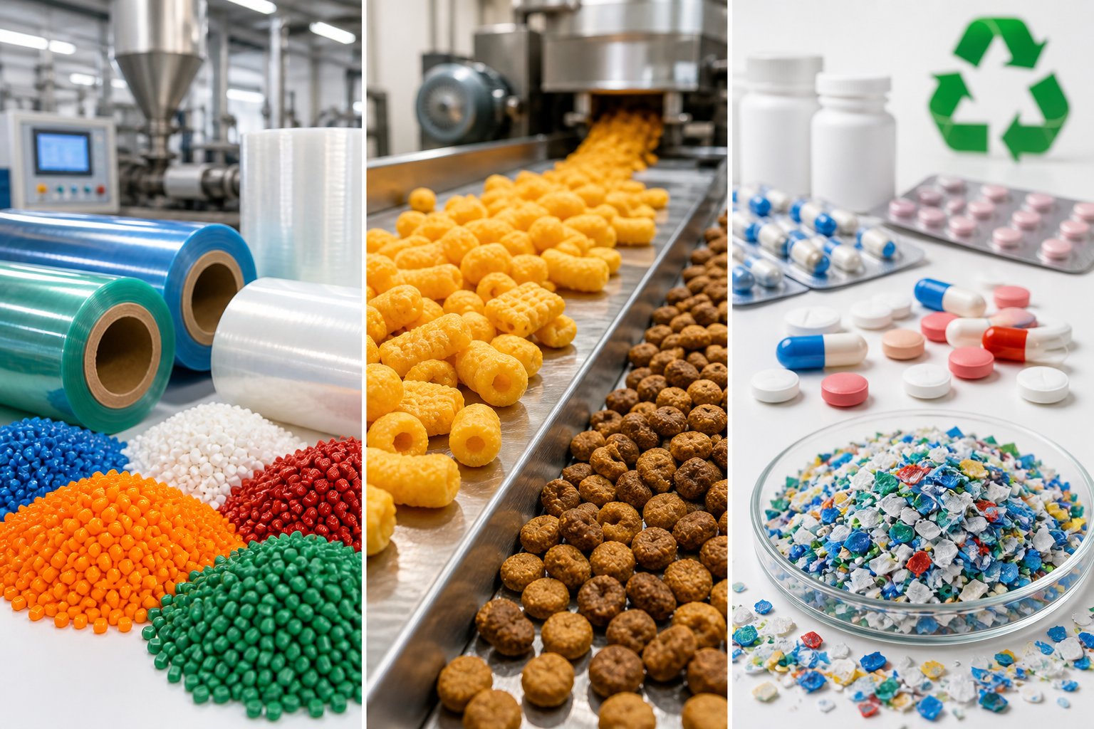
Feeding mechanics and venting capabilities shape what each extruder type can handle, but the real proof of those capabilities shows up in application diversity. Most comparisons limit themselves to plastics compounding or, occasionally, snack food production. That narrow lens misses a much larger picture. Single and twin screw extruders serve industries ranging from pharmaceutical manufacturing to post-consumer recycling, and the right machine for each sector depends on how those feeding, mixing, and devolatilization strengths map to specific product requirements.
Plastics Compounding and Polymer Processing
Plastics compounding remains the single largest market for twin screw compounding extruders. When a formulation calls for blending polymer pellets with pigments, fillers, reinforcing fibers, or stabilizers, co-rotating twin screw machines deliver the distributive and dispersive mixing intensity required to produce a homogeneous compound in a single pass. Masterbatch production, color concentrate manufacturing, and highly filled compound formulations all rely on this architecture.
Consider the challenge of incorporating 70-80% calcium carbonate or talc by weight into a polyolefin matrix. As detailed in a Plastics Technology technical article, a compounding twin screw extruder handling these high mineral-filler loadings must manage enormous volumes of entrained air, stage filler incorporation across multiple side feeders, and vent exhausted air without expelling unincorporated powder through the vent ports. Single screw machines simply lack the modular barrel architecture and starve-fed zone control to handle such formulations.
Where do single screw plastic extruders dominate? Melt-and-shape applications using pre-compounded pellets. Blown film, cast film, sheet extrusion, pipe, and profile lines overwhelmingly use single screw designs because the material arrives already fully compounded. The extruder's job is straightforward: melt the pellets uniformly and generate enough pressure to push the melt through a forming die. A single screw machine does this at lower capital cost, with simpler operation and higher volumetric output per dollar invested. An extruder for polymer processing does not need aggressive mixing when the mixing was already completed upstream.
Food, Snacks, and Pet Food Extrusion
Walk down a snack aisle and you are looking at extruded products everywhere. Corn curls, onion rings, chipsticks, puffed cereals, and shaped pet food kibble all pass through an extruder barrel before reaching the shelf. The question of which machine to use depends on the complexity of the formulation and the texture you are targeting.
Single screw extruders have produced expanded snacks for decades. As CFAM International notes, single screw extrusion has long been used to manufacture common foods including spaghetti, macaroni, onion rings, corn curls, and chipsticks. For simple formulations based on a single starch source with minimal additives, these machines provide reliable, cost-effective production with straightforward operation.
The landscape shifts when snack producers want more than a basic puffed shape. Center-filled snacks, multi-textured products, and complex formulations involving multiple protein sources, fiber blends, or specialty coatings demand the kind of mixing flexibility and cooking control that only co-rotating twin screw extruders provide. The twin screw's independent throughput and speed control allows precise management of the cooking intensity, hydration level, and mechanical energy input that together determine final product texture. Pet food manufacturers face similar requirements, often processing formulations that include fresh meat slurries, vegetable fibers, and vitamin premixes that need thorough blending without overheating any single component.
For producers evaluating whether to expand capacity, the decision often comes down to a choice CFAM frames clearly: buy more single screw machines for higher output of existing products, or invest in twin screw capability that unlocks entirely new product categories and quality tiers.
Pharmaceuticals, Recycling, and Emerging Applications
Perhaps the fastest-growing application for extrusion technology sits outside traditional plastics entirely. Hot melt extrusion (HME) in pharmaceutical manufacturing uses co-rotating twin screw extruders to create amorphous solid dispersions, a formulation strategy that improves the bioavailability of poorly water-soluble drug compounds. A hot melt extruder processes a blend of active pharmaceutical ingredient (API) and polymer carrier through precisely controlled temperature and shear profiles, producing a molecularly dispersed solid solution without the need for solvents.
Why twin screws? The narrow residence time distribution, precise temperature zoning, and self-wiping geometry prevent localized hot spots that could degrade sensitive APIs. Pharmaceutical applications also demand absolute batch-to-batch consistency and full traceability, requirements that align perfectly with the metered starve-feeding and modular screw design of co-rotating systems. Much of the early-stage formulation development work in HME happens on a lab extruder or laboratory extruder with screw diameters as small as 10-16 mm, allowing researchers to screen polymer-API combinations using minimal quantities of expensive active ingredients. These lab scale extruder platforms replicate the exact screw element configurations and process conditions of production-scale machines, making scale-up far more predictable than with other formulation technologies.
Recycling represents another rapidly expanding frontier. Post-consumer plastic flake arrives contaminated with residual moisture, printing inks, adhesive residues, and mixed polymer fractions. Processing this material into usable pellets demands exactly the combination of feeding flexibility, multi-stage devolatilization, and aggressive mixing that co-rotating twin screw extruders deliver. A compounding extruder equipped with multiple vacuum vent ports and fine filtration can take contaminated post-consumer PE or PP flake and produce pellets suitable for injection molding or film production in a single pass, consolidating what would otherwise require separate washing, drying, and compounding steps.
On the emerging technology front, 3D printing filament production has opened a growing market for small-scale single screw extrusion systems. Producing uniform 1.75 mm or 2.85 mm filament from commodity resins like PLA or PETG is fundamentally a melt-and-shape task that does not require intensive mixing, placing it squarely in the single screw sweet spot. Hobbyist and small-business filament makers benefit from the lower capital cost and operational simplicity of compact single screw lines, many of which draw design principles from laboratory-scale machines.
Multi-Industry Application Matrix
The following table maps extruder type against industries and specific product examples, providing the cross-industry reference that most extruder comparisons overlook entirely:
| Industry | Single Screw Extruder | Co-Rotating Twin Screw Extruder | Counter-Rotating Twin Screw Extruder |
|---|---|---|---|
| Plastics - Film & Sheet | Blown film (PE, PP), cast film, stretch wrap, agricultural mulch film | Specialty multilayer film requiring in-line compounding | Rarely used |
| Plastics - Pipe & Profile | PE/PP pipe, simple profiles from pre-compounded resin | Rarely used for direct shape extrusion | PVC pipe, PVC window profiles, PVC siding, WPC decking |
| Plastics - Compounding | Limited to simple color blending with mixing screws | Masterbatch, color concentrates, glass-fiber-reinforced compounds, mineral-filled compounds, polymer alloys | Some PVC compound preparation |
| Food - Snacks | Simple expanded corn snacks, puffed rice, basic extruded shapes | Center-filled snacks, multi-texture products, high-protein snacks, complex formulations | Rarely used in food applications |
| Food - Pet Food & Feed | Basic kibble shapes from simple grain formulations | Multi-component pet food with fresh meat, fiber, and vitamin premixes; aquafeed | Rarely used |
| Pharmaceuticals | Rarely used | Hot melt extrusion for amorphous solid dispersions, sustained-release dosage forms, API-polymer blends | Rarely used |
| Recycling | Clean, pre-sorted regrind of single-polymer streams | Contaminated post-consumer flake requiring devolatilization, homogenization, and filtration | Some PVC recyclate reprocessing |
| Rubber & Elastomers | Rubber straining, hose extrusion, tire tread profiles | Silicone compounding, TPE blending | Rubber sheeting, calender feeding |
| 3D Printing Filament | PLA, PETG, ABS filament production (1.75 mm / 2.85 mm) | Specialty composite filaments (carbon fiber, wood fill) | Rarely used |
| Adhesives & Sealants | Simple hot-melt adhesive sticks | Reactive hot-melt adhesives, pressure-sensitive adhesive compounding | Rarely used |
A few patterns stand out immediately. Co-rotating twin screw machines appear in nearly every row because their mixing and process flexibility suit any application involving multi-component formulations. Single screw extruders dominate wherever the task is melting a pre-compounded material and pushing it through a die. Counter-rotating designs concentrate almost exclusively in PVC-related processing and a handful of gentle-shear applications where their pressure-building strength and tight residence time control provide a decisive advantage.
The right column for your operation depends on where your product sits in this matrix, but choosing the machine is only one piece of the cost equation. Capital expenditure gets all the attention during procurement, while the ongoing costs of energy consumption, spare parts, and maintenance quietly accumulate into a total cost of ownership that can either validate or undermine that initial purchasing decision.
Total Cost of Ownership and Energy Efficiency Compared
Purchase price dominates most extruder procurement conversations, and for understandable reasons: it is the one number that appears on a quote in black and white. But the sticker price is only the opening chapter of a much longer financial story. Energy bills, spare parts, unplanned downtime, and the hidden cost of pre-processing steps accumulate month after month, often dwarfing the original capital outlay within a few years. Engineers who evaluate a twin screw extruder machine or a single screw alternative based solely on what it costs to buy are almost guaranteed to misjudge what it costs to own.
Capital Cost and Purchase Price Considerations
There is no getting around it: twin screw extruder price tags run significantly higher than single screw machines of comparable throughput capacity. The reasons are mechanical. A double screw extruder machine requires a complex high-torque gearbox that splits power across two shafts, dual-drive motors, and a modular barrel and screw element system where each individual kneading block, conveying element, and barrel segment is precision-machined to tight tolerances. These components add up fast.
Industry pricing data illustrates the gap clearly. A mid-range single screw extrusion machine in the 90 mm class might fall in the range of $65,000 to $90,000, while a co-rotating twin screw extruder with similar output capacity can range from $150,000 to $210,000, representing a premium of roughly 130% or more. Scale up to larger production machines and the absolute dollar gap widens further, with high-performance compounding twin screw systems reaching $350,000 to $490,000 depending on configuration and ancillary equipment.
Does that mean single screw machines are always the budget-friendly choice? For straightforward melt-and-shape applications, yes. But capital cost comparisons become misleading when the twin-screw extruder machine consolidates processing steps that would otherwise require separate upstream equipment. A compounding operation that eliminates a standalone pre-mixing step, a separate drying system, or a secondary pelletizing pass may actually require less total capital investment when viewed as an integrated line rather than an isolated machine.
Energy Consumption Per Kilogram of Output
Energy costs are the quiet budget killer in any extrusion operation, running 24 hours a day, 300-plus days a year. At first glance, single screw extruders appear more energy efficient. Their simpler drive systems, lower torque requirements, and lower screw speeds translate into less power consumption per hour of operation for basic melting tasks. When processing homogeneous, pre-compounded pellets into film, sheet, or pipe, a single screw machine delivers excellent specific energy consumption, typically measured in kilowatt-hours per kilogram of output.
The picture flips, however, when you zoom out from the machine to the entire process. Imagine a production line where a single screw extruder processes material that first required a separate pre-compounding step on another machine, followed by pelletizing, cooling, drying, and refeeding. Each of those steps consumes energy, floor space, and labor. A twin screw extruder machine that performs feeding, melting, mixing, devolatilization, and pelletizing in a single pass eliminates those upstream energy inputs entirely.
One useful way to think about this: compare total system energy per kilogram of finished product rather than machine-level energy per hour. A twin screw line consuming 0.25 kWh/kg in a single consolidated pass may actually beat a single screw line consuming 0.18 kWh/kg when the upstream compounding, drying, and re-melting steps add another 0.15 kWh/kg that never appears on the extruder's power meter. The right question is not "which machine uses less electricity" but "which process chain delivers a finished kilogram with less total energy."
Spare Parts, Downtime, and Long-Term Operating Cost
Here is where the cost equation gets genuinely counterintuitive. Twin screw extruders have more components, more wear surfaces, and more complex gearboxes than single screw machines. You would expect their long-term maintenance costs to be higher across the board. And in absolute terms, annual maintenance budgets for twin screw systems do tend to run larger, with one industry analysis estimating twin screw maintenance costs roughly double those of comparable single screw machines in similar service.
But the modularity that drives higher capital cost also delivers a structural maintenance advantage. When a kneading block wears out on a twin screw machine, you slide that individual element off the splined shaft and replace it. Cost: one element. When the compression zone wears on a single screw machine, you are typically looking at refurbishing or replacing the entire one-piece screw and potentially reboring or relining the barrel. Cost: significantly higher per replacement event, even if those events occur less frequently.
Downtime cost amplifies this difference. Swapping a worn twin screw element can be done during a planned maintenance window in hours. Replacing an entire single screw or sending a barrel out for rework can mean days of lost production. In a 24/7 operation running high-value compounds, even one extra day of downtime per year can cost more than a full set of replacement kneading blocks.
To make a fair comparison, engineers should build a total cost of ownership model that captures every category where money flows out of the operation. The following framework covers the essential cost buckets:
- Capital expenditure: Purchase price, installation, commissioning, and any required auxiliary equipment such as feeders, vacuum systems, or downstream pelletizers.
- Energy consumption: Total system energy per kilogram of finished product, including upstream pre-processing steps that the extruder selection may eliminate or require.
- Spare parts and consumables: Screw elements, barrel liners, heater bands, thermocouples, and gearbox components, tracked per kilogram of output rather than per calendar year.
- Maintenance labor: Planned and unplanned maintenance hours, including the skill level and availability of technicians qualified to service each machine type.
- Downtime cost: Lost production value during both scheduled maintenance windows and unplanned breakdowns, weighted by the revenue impact of each hour offline.
- Process flexibility value: The ability to run multiple formulations, accommodate material changes, or switch product grades without hardware modifications, expressed as either revenue opportunity gained or capital avoided.
Most procurement decisions focus on item one and ignore items two through six. That is exactly how a seemingly cheaper machine ends up costing thousands more over its operating life. The engineer who builds a complete TCO model before signing a purchase order almost always makes a different, and better, decision than the one who compares quotes alone.
Of course, total cost of ownership only tells part of the story if the machine is wearing out faster than expected. Abrasive fillers, corrosive polymers, and high-shear processing conditions all attack screw flights and barrel liners in predictable but often overlooked patterns, and those wear patterns differ significantly between single and twin screw architectures.
Maintenance, Wear Patterns, and Screw Barrel Replacement
Every extruder screw starts wearing the moment it begins rotating inside the barrel. That is not a defect or a design flaw; it is physics. Metal surfaces under pressure, surrounded by abrasive particles and corrosive melt, will gradually lose material. The real question is not whether wear happens, but where it concentrates, how fast it progresses, and what you do about it before process stability slips away. Most engineers pay close attention to screw geometry and process parameters during equipment selection, then give surprisingly little thought to the wear patterns that will ultimately determine how long those carefully chosen specifications actually hold.
Common Wear Patterns in Single and Twin Screw Barrels
Three distinct wear mechanisms attack plastic extruder screw and barrel surfaces, often simultaneously. Understanding which type dominates your process determines the right metallurgy, inspection strategy, and replacement timeline.
Abrasive wear is the most common culprit in plastics processing. Hard particles, whether glass fibers, calcium carbonate, talc, or mineral flame retardants, act like sandpaper against screw flight lands and extrusion barrel inner surfaces. As Plastics Technology notes, abrasive wear becomes significant when processing resins with fillers, additives, or contaminants, and some of the most aggressive fillers can reduce screw and barrel useful life by 50% or more. Glass-fiber-reinforced compounds are especially punishing because the fibers are harder than most barrel liner materials and maintain their abrasive edge throughout the melt zone.
Adhesive wear occurs when metal-to-metal contact happens between the screw flight tip and the barrel wall. Extremely high localized stresses cause the surfaces to briefly weld together, then fracture apart, tearing material from one or both surfaces. You will spot adhesive wear as scoring, galling, or a characteristic "rolled" burr along the trailing edge of the screw flight. This type of wear is often triggered by screw deflection, misalignment, or solids wedging, a condition where unmelted pellets jam the channel and force the screw sideways against the barrel bore.
Corrosive wear attacks the metal chemically rather than mechanically. Processing PVC releases hydrochloric acid at elevated temperatures. Fluoropolymers generate hydrofluoric acid. Even some flame-retardant additives produce corrosive byproducts. The resulting chemical attack weakens the surface layer, making it vulnerable to mechanical removal by the flowing polymer. Corrosion and abrasion often work in tandem: corrosion softens the surface, and normal conveying forces strip away the weakened material far faster than either mechanism alone would cause.
Here is where the single and twin screw extruder distinction matters for maintenance planning. In a single screw machine, wear concentrates heavily in the compression zone, where the decreasing channel depth forces maximum solid-to-barrel contact and generates the highest pressures and shear rates. The screw flight tips in this region lose diameter first, and the barrel bore opposite the compression zone enlarges fastest. As the gap grows, more melt leaks backward over the flights instead of being pumped forward, quietly reducing output and raising discharge temperatures before anyone notices a problem.
In twin screw configurations, wear patterns shift to the kneading blocks and high-shear mixing zones. These elements impose the most intense mechanical energy on the melt and are where abrasive fillers do their greatest damage. The intermesh region between the two screws also experiences wear, particularly in counter-rotating designs where opposing screw rotation can cause deflection-related contact at higher speeds. Barrel extruder liners opposite kneading sections wear faster than those in conveying zones, creating localized bore enlargement that degrades mixing efficiency before overall output drops measurably.
The critical takeaway? As screw-to-barrel clearances open up from wear, process stability degrades before outright failure occurs. Typical original clearances run approximately 0.001 inch per side per inch of screw diameter. A screw plastic extruder operating at nominal clearance delivers precise shear rates, tight temperature control, and consistent output. Double that clearance through wear, and you lose melt pressure, gain discharge temperature variability, and start seeing inconsistencies that operators compensate for by adjusting speed, temperature, and backpressure, often accelerating further wear in the process. As one maintenance guide emphasizes, the business impact is straightforward: wear increases the chance you will miss production targets and increases the odds you will run hotter and faster to compensate.
Preventive Maintenance Strategies and Replacement Schedules
Waiting until output collapses or black specks appear in the product is not a maintenance strategy. It is an emergency. Effective screw and barrel maintenance revolves around measurement-driven trending that spots gradual degradation long before it becomes a crisis.
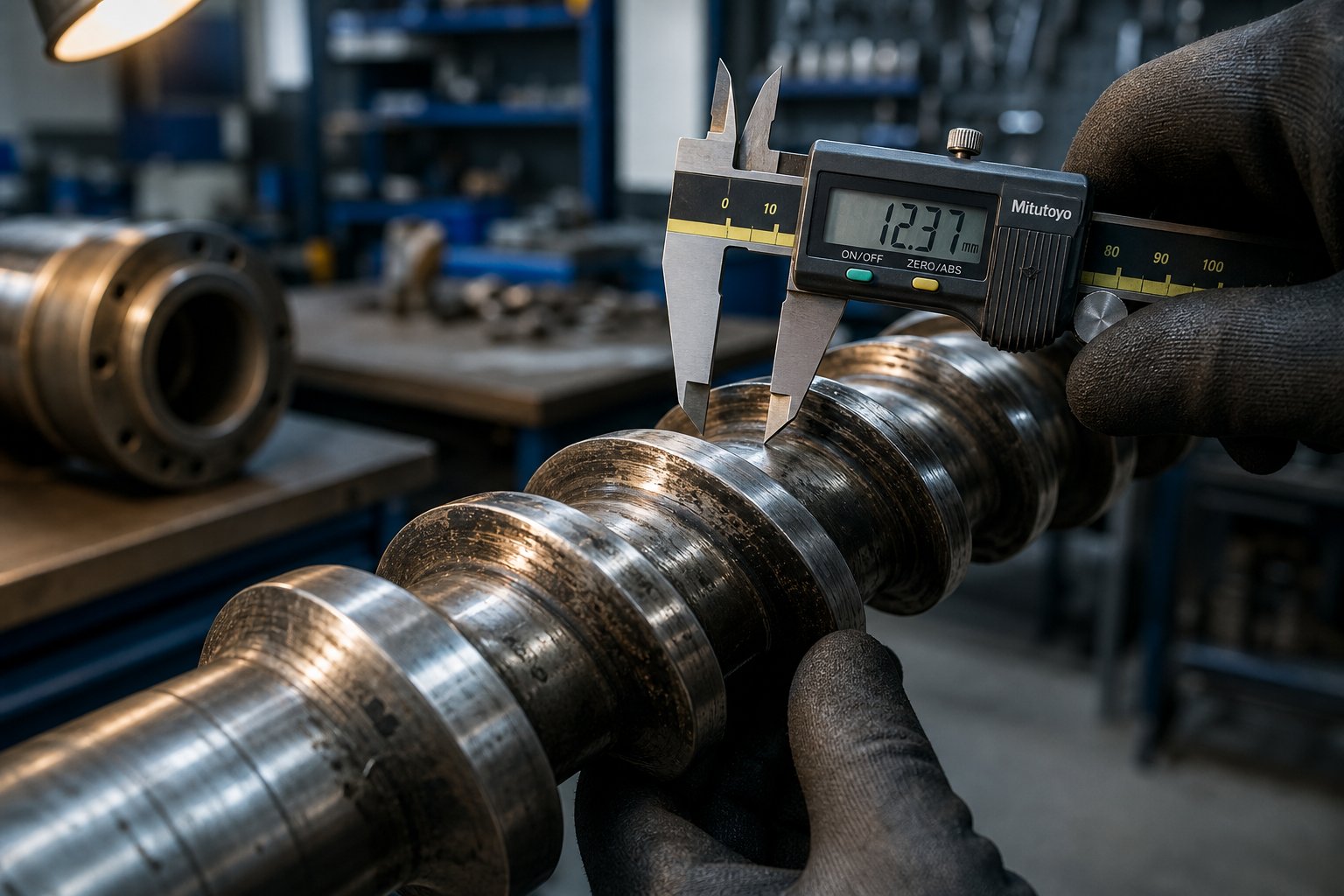
Inspection intervals depend on what you are processing. Lines running unfilled polyolefins might go 12 to 18 months between screw pulls without measurable wear. Lines running 40% glass-fiber-reinforced nylon may need measurement every 2,000 to 3,000 operating hours. The key is establishing a baseline at installation, recording bore diameter and screw flight OD at standardized locations, and then trending those numbers at consistent intervals using the same tools and measurement points every time.
Clearance measurement is the most reliable indicator of wear progression. Use a bore gauge for the barrel ID and micrometers or calipers for screw flight OD. Record results by zone, not just as a single average, because wear is never uniform along the barrel length. A single screw machine might show 0.003-inch wear in the compression zone and virtually zero in the metering zone, masking a real problem behind a healthy-looking average.
Gearbox servicing follows a separate but equally important schedule. Twin screw gearboxes operate under high torque loads with tight gear meshing tolerances. Oil analysis, vibration monitoring, and scheduled oil changes at manufacturer-recommended intervals prevent the kind of catastrophic gearbox failure that can sideline a production line for weeks rather than days.
This is where twin screw modularity delivers a genuine maintenance advantage. When a kneading block wears beyond tolerance, you slide that single element off the splined shaft and replace it. The remaining screw elements, which may still be well within spec, stay in service. Contrast this with a single screw machine, where the entire one-piece screw often must be removed and sent for refurbishment or replaced outright, even when wear is concentrated in a small section of the overall length.
When it comes time to source replacement components, having a reliable supplier with a broad product range matters more than most engineers realize during the planning stage. NANHAIYA's screw barrel product catalog, for example, lets engineers compare single screw, parallel twin screw, conical twin screw, and spare-part options side by side, which can streamline the specification and quoting process when building a replacement parts inventory or planning a scheduled overhaul.
The following best practices will help extend screw and barrel life regardless of which architecture you operate:
- Establish baseline measurements at installation. Record barrel bore ID and screw flight OD at standardized axial positions before the first production run. These numbers become your wear reference for every future inspection.
- Track process indicators between inspections. Specific output rate (kg/hr/RPM), discharge melt temperature, and motor current at constant setpoints all shift as clearances open. Log these values weekly and trend them to spot degradation between physical inspections.
- Use compatible metallurgies. Match screw flight hardfacing alloys to barrel liner materials. Incompatible metal pairs accelerate adhesive wear. Consult your component supplier to verify compatibility when specifying replacements.
- Protect against foreign material. Install magnetic traps and metal detectors upstream of the feed throat. A single bolt or grinder blade entering the barrel can cause more damage in seconds than months of normal processing.
- Clean screws carefully during material changes. Avoid hard steel brushes, chisels, or aggressive tools that scratch polished screw surfaces. Scratches create new hang-up zones that promote material degradation and make future cleaning harder.
- Replace screw and barrel as a matched pair when wear is advanced. Installing a new screw into a worn barrel, or vice versa, rarely recovers full performance because the mating surface remains out of tolerance.
- Maintain alignment between the barrel, gearbox, and drive motor. Misalignment is one of the leading root causes of adhesive wear. Check alignment at installation and after any major maintenance event that involves disconnecting the drive train.
- Keep a critical spare parts inventory. Having replacement kneading blocks, barrel liners, or a spare screw on the shelf eliminates the gap between recognizing a wear problem and resolving it. Unplanned lead times for custom screw components can stretch to weeks, turning a manageable maintenance event into an extended production loss.
The pattern across all of these practices is the same: measure, trend, plan, and act before wear forces your hand. Reactive maintenance is always more expensive than preventive maintenance, not because the parts cost more, but because the unplanned downtime and scrap produced during the failure window dwarf the cost of a scheduled replacement.
Wear patterns and maintenance realities reinforce an important truth about extruder selection: there is no universally "better" machine. Each architecture concentrates wear differently, requires different spare parts strategies, and rewards different maintenance approaches. That same principle applies to nearly every aspect of the single-versus-twin debate, which is why the most persistent myths about extruder selection deserve a closer look.
Common Misconceptions About Extruder Selection Debunked
Wear patterns differ between machine types. Maintenance strategies differ. Energy profiles differ. Yet despite all the nuance covered in the previous sections, three stubborn myths continue to drive purchasing decisions in the wrong direction. These misconceptions do not come from ignorance. They come from oversimplification, from sales pitches absorbed uncritically, and from engineers generalizing one successful experience into a universal rule. Each myth sounds reasonable on the surface. Each one can cost you thousands.
Myth: Twin Screw Is Always the Better Choice
This is the most expensive misconception in the extruder world. It usually sounds something like: "Twin screw machines do everything a single screw can do, plus more, so why would you ever buy a single screw?" The logic feels airtight until you put a price tag on it.
For many straightforward melt-and-shape applications, a single screw plastic extruder is not just adequate. It is genuinely superior. Blown film, cast film, pipe extrusion, and profile production using pre-compounded pellets all fall squarely into this category. These processes need steady melting, consistent pressure generation, and reliable die feeding. They do not need intensive distributive mixing, modular screw reconfiguration, or multi-stage devolatilization. As one technical comparison puts it, the common mistake is to treat twin screw as "better" and single screw as "basic," when in real extrusion lines, the better machine is the one that solves the actual processing problem without adding unnecessary cost, cleaning, wear, and operator burden.
Consider the numbers. A plastic single screw extruder in the 90 mm class costs roughly half what a co-rotating twin screw machine of similar output capacity commands. It requires fewer spare parts, simpler operator training, less cleaning discipline between material changes, and a smaller maintenance budget. For a PE pipe line running a single pre-compounded resin 24 hours a day, that price premium buys capability the process will never use. Multiply the wasted capital by a multi-line plant, and the financial damage from this myth becomes substantial.
The right question is never "which machine is more advanced?" It is "does my process actually need what this machine offers?" If the material arrives as uniform pellets and the extruder's job is simply to melt and meter, single screw wins on cost, simplicity, pressure generation, and volumetric output per dollar.
Myth: Single Screw Extruders Cannot Mix
This myth is the mirror image of the first one, and it is equally misleading. You will hear it from engineers who have worked exclusively with twin-screw extruders and assume that a single screw channel offers nothing beyond drag-flow conveying with zero mixing action. The reality is more nuanced.
It is true that a conventional metering-zone screw provides limited distributive mixing. The helical channel creates a relatively orderly flow pattern that does not aggressively redistribute minor components. But screw designers recognized this limitation decades ago and developed a range of mixing elements that dramatically improve single screw mixing performance for many practical applications.
Maddock (or Leroy/UCC) mixers are among the most widely used. As extrusion authority Jim Frankland explains in Plastics Technology, these dispersive shear devices date to the late 1960s and saw immediate acceptance because they greatly improved both output and melt quality, particularly with crystalline polyolefins. A spiral Maddock variant that combines features of both the original Maddock and Egan designs is now the most common configuration.
Barrier screws represent another significant advancement. By separating the solid bed from the melt pool using a secondary flight, barrier designs control melting far more precisely than conventional single-flight screws. Frankland notes that barrier screws largely eliminated the need for supplemental shear mixers altogether, since melting could be controlled and completed within the barrier section itself.
Beyond these, pineapple mixers divide the melt into converging streams at various angles, creating chaotic mixing that is especially effective for color distribution. Pin mixers create exponential divisions of the melt based on the number of pins and rows, minimizing laminar flow restrictions and handling materials of substantially varying viscosity. Saxton-style distributive mixers use interrupted flights to promote cross-channel flow with minimal pressure drop.
The key insight from Frankland's analysis applies broadly: for barrier screws already producing a fully melted stream, a distributive mixer is usually the better addition, providing thermal homogenization, color blending, or additive distribution without the unnecessary melt temperature increase and output reduction that a dispersive shear mixer would cause. That is not "no mixing." That is targeted, application-appropriate mixing using a simpler, less expensive machine.
Can a single screw machine match a co-rotating twin screw extruder's dispersive mixing intensity for a 60% calcium carbonate compound? No. But for blending color concentrates into a polyolefin base, homogenizing melt temperature across the channel, or distributing modest levels of additives, a well-designed single screw with the right mixing section handles the job reliably and economically. Dismissing single screw mixing capability entirely leads engineers toward twin screw solutions for applications where a $15,000 screw upgrade would have solved the problem.
Myth: Twin Screw Extruders Are Always More Expensive to Operate
This myth comes from looking at the machine in isolation rather than the process as a whole. A twin screw plastic extruder does consume more energy per hour, requires more expensive spare parts, and demands higher-skilled operators than a comparable single screw system. Those facts are real. But they are not the whole equation.
When twin-screw extruders are applied to the processes they were designed for, compounding, reactive extrusion, devolatilization, and multi-component formulation blending, they often consolidate steps that would otherwise require separate machines, each with its own energy draw, labor requirement, material loss, and quality risk. A compounding line that eliminates a standalone pre-mixer, a separate pelletizing step, and an intermediate drying stage removes three sets of equipment costs, three material handling steps, and three opportunities for yield loss.
Material waste reduction is another factor that rarely appears in cost comparisons but hits the bottom line hard. Better mixing uniformity from twin screw compounding means fewer off-spec pellets, fewer rejected parts downstream, and less regrind cycling through the system. For high-value engineering resins or specialty compounds where raw material costs dominate the cost structure, even a 1-2% improvement in first-pass yield can offset the higher operating cost of the twin screw machine within months.
The honest calculation compares total cost per kilogram of finished, in-spec product across the entire process chain, not just the electricity bill on one machine. When that broader view is applied, twin screw systems frequently deliver lower per-kilogram costs despite higher per-machine operating expenses, precisely because they reduce the number of machines, handling steps, and waste-generating process transitions required to reach the same endpoint.
The right extruder is not the more advanced machine or the cheaper machine. It is the one whose capabilities match your specific process requirements. Every myth about extruder selection traces back to the same error: applying a universal ranking to a decision that is always application-specific.
Debunking these myths clears away the noise, but it still leaves a practical question on the table: given everything covered in this guide, how do you actually walk through the selection process step by step and land on the right configuration for your specific operation?
How to Choose the Right Extruder for Your Process
Myths aside, the decision between a single and twin screw extruder comes down to a structured evaluation rather than gut instinct or brand loyalty. The following framework distills every principle covered in this guide into a repeatable selection methodology you can apply regardless of industry, material, or production scale.
Step-by-Step Extruder Selection Framework
Walk through these five steps in order. Each one narrows the field, and skipping any of them is where costly mismatches originate.
- Define your material and formulation complexity. Are you processing a single pre-compounded resin, or blending multiple polymers with fillers, fibers, and additives? Simple single-material melting points toward single screw. Multi-component formulations requiring dispersion and distribution point toward co-rotating twin screw. Heat-sensitive materials like PVC steer toward counter-rotating configurations. Revisit the feeding and material sensitivity guidance in earlier sections for deeper context.
- Determine required mixing and devolatilization intensity. Does your process demand dispersive mixing of agglomerated pigments or nanofillers? Do you need to strip moisture, residual monomers, or volatile organic compounds from the melt? High mixing and multi-stage devolatilization requirements strongly favor twin screw architectures with modular screw elements and vent ports.
- Evaluate throughput and flexibility requirements. Will the line run a single product 24/7, or switch between formulations weekly? High-volume, single-product operations benefit from the simplicity and output efficiency of single screw systems. Facilities needing frequent changeovers or running short campaigns across many formulations gain from the reconfigurable screw profiles and independent feed control of twin screw machines. For early-stage R&D or formulation screening, a benchtop twin screw extruder or lab scale twin screw extruder may be the most cost-effective starting point before committing to production-scale equipment.
- Calculate total cost of ownership including maintenance and energy. Build a TCO model covering capital, energy per kilogram, spare parts, maintenance labor, downtime, and process flexibility value. Do not compare machine purchase price in isolation. A twin screw system that consolidates three processing steps into one pass may deliver lower per-kilogram cost despite a higher sticker price.
- Source and compare screw barrel options from qualified suppliers. Once you have narrowed the architecture, request quotes from multiple twin screw extruder manufacturers and single screw extruder manufacturers who can supply both the complete machine and replacement wear components. Evaluate each twin-screw extruder manufacturer on metallurgy options, lead times, and their ability to supply individual screw elements and barrel segments for long-term maintenance. NANHAIYA's screw barrel product collection offers a practical starting point for comparing single screw, parallel twin screw, conical twin screw, and spare-part configurations side by side, which maps directly to the architecture decision you have already made in steps one through three.
Matching Your Application to the Right Extruder Type
The table below synthesizes the application guidance from this entire article into a quick-reference decision tool. Find your processing scenario in the left column, and the recommended configuration follows immediately.
| Processing Scenario | Recommended Extruder Configuration | Key Reason |
|---|---|---|
| Simple melt extrusion (film, sheet, pipe from pre-compounded pellets) | Single Screw | Lowest cost, excellent pressure generation, straightforward operation |
| Compounding with mineral fillers or glass fibers | Co-Rotating Twin Screw | High dispersive and distributive mixing, staged side feeding, air venting |
| Reactive extrusion (grafting, crosslinking, polymerization) | Co-Rotating Twin Screw | Precise residence time control, modular zone design, narrow RTD |
| Devolatilization-heavy processes (solvent removal, moisture stripping) | Co-Rotating Twin Screw | Multi-stage vacuum venting, partially filled channels, surface renewal |
| PVC pipe and profile extrusion | Counter-Rotating Twin Screw (conical) | Low shear, high pressure, tightest residence time for heat-sensitive PVC |
| Masterbatch and color concentrate production | Co-Rotating Twin Screw | Superior pigment dispersion, self-wiping prevents cross-contamination |
| Recycled post-consumer flake reprocessing | Co-Rotating Twin Screw | Handles variable feedstock, multi-stage devolatilization, homogenization |
| 3D printing filament production | Single Screw | Simple melt-and-shape task, low capital cost, compact footprint |
| Pharmaceutical hot melt extrusion | Co-Rotating Twin Screw | Precise thermal control, narrow RTD, batch-to-batch consistency |
Where to Start Your Equipment and Parts Search
With your architecture selected and application matched, the practical next steps are straightforward. Request detailed proposals from at least two or three qualified suppliers, specifying not just the machine but also the screw element configurations, barrel metallurgy options, and spare parts packages you will need for the first two to three years of operation. Ask each twin screw extruder for sale listing or single screw quote to include specific energy consumption data at your target throughput, gearbox torque ratings, and references from customers running similar materials.
Do not overlook the screw and barrel supply chain. Your production uptime over the next decade depends as much on having the right replacement components available on short lead times as it does on selecting the right machine architecture today. Build a relationship with a screw barrel supplier early, compare their product range against the configurations identified in your TCO model, and stock critical wear elements before they are needed rather than after a production crisis forces an emergency order.
The single and twin screw extruder decision is ultimately an engineering judgment, not a brand preference or a budget shortcut. Apply the framework above, ground your evaluation in the technical realities covered throughout this guide, and the right machine for your process will identify itself.
Frequently Asked Questions About Single and Twin Screw Extruders
1. What is the main difference between a single screw and twin screw extruder?
The fundamental difference lies in the conveying mechanism. A single screw extruder uses drag-flow conveying, where material moves forward through friction between the polymer and barrel wall. A twin screw extruder uses positive displacement conveying, where two intermeshing screws mechanically push material forward regardless of feedstock properties. This distinction drives every downstream difference in mixing intensity, residence time control, throughput flexibility, and application suitability. Single screw machines excel at melting pre-compounded pellets for shaping operations, while twin screw systems handle multi-component compounding, devolatilization, and reactive processing where independent control of speed and throughput is essential.
2. When should I choose a single screw extruder over a twin screw extruder?
A single screw extruder is the superior choice for straightforward melt-and-shape applications such as blown film, cast film, pipe, and profile extrusion using pre-compounded pellets. These processes require steady melting, consistent pressure generation, and reliable die feeding rather than intensive mixing or devolatilization. Single screw machines offer lower capital cost (often 50% less than comparable twin screw systems), simpler operation, fewer spare parts, and excellent volumetric output per dollar. If your material arrives as uniform pellets and the extruder only needs to melt and meter, investing in twin screw capability adds cost without adding value. For sourcing replacement screws and barrels for either type, suppliers like NANHAIYA (nhyscrews.com/products) offer side-by-side comparison of single screw, parallel twin screw, and conical twin screw configurations.
3. What is the difference between co-rotating and counter-rotating twin screw extruders?
Co-rotating twin screw extruders have both screws turning in the same direction, creating a figure-eight flow path with high shear, excellent distributive mixing, and self-wiping geometry that eliminates dead spots. They dominate compounding, masterbatch production, reactive extrusion, and pharmaceutical hot melt extrusion, operating at speeds up to 1,200 RPM. Counter-rotating twin screw extruders have screws turning in opposite directions, producing a calendering effect in the nip region that generates high pressure with lower shear. Conical counter-rotating designs are the standard for PVC pipe and profile extrusion, where gentle processing prevents thermal degradation. Co-rotating machines prioritize mixing flexibility, while counter-rotating machines prioritize pressure buildup and the narrowest possible residence time distribution.
4. How does the L/D ratio affect extruder performance?
The length-to-diameter (L/D) ratio sets the available processing length inside the barrel, directly controlling residence time, mixing quality, and the number of functional zones (feeding, compression, metering, venting) that can be staged along the screw. Single screw extruders typically range from 24:1 to 36:1, limited by screw deflection and shaft stress at longer lengths. Co-rotating twin screw machines routinely run 36:1 to 48:1, with high-performance compounding systems reaching 56:1 to 60:1 thanks to modular element-on-shaft construction. Counter-rotating twin screws for PVC use shorter ratios of 18:1 to 24:1 because their positive displacement pumping does not benefit from extra length, and keeping residence time short protects heat-sensitive PVC. A practical rule: only add L/D if you can specify a clear function for the additional length.
5. Are twin screw extruders always more expensive to operate than single screw extruders?
Not necessarily. While twin screw extruders do consume more energy per hour and carry higher spare parts costs on a per-machine basis, total operating cost depends on the entire process chain. A twin screw system that consolidates feeding, melting, mixing, devolatilization, and pelletizing into a single pass can eliminate upstream pre-compounding, drying, and re-melting steps that each consume energy and labor. Better mixing uniformity also reduces off-spec output and material waste. When engineers compare total cost per kilogram of finished, in-spec product rather than just the electricity bill on one machine, twin screw lines frequently deliver lower per-kilogram costs for compounding and multi-step processes. For simple melt-and-shape operations, however, single screw machines do maintain a clear operating cost advantage.
Written by
Nanhaiya Technical Team
Zhoushan Nanhaiya Plastic Machinery Co., Ltd.
The Nanhaiya technical team supports screw and barrel manufacturing projects through application review, technical communication, custom manufacturing coordination, and production and quality control.
Discuss Your Application
Related Articles
More insights on screw barrel technology and plastics processing.
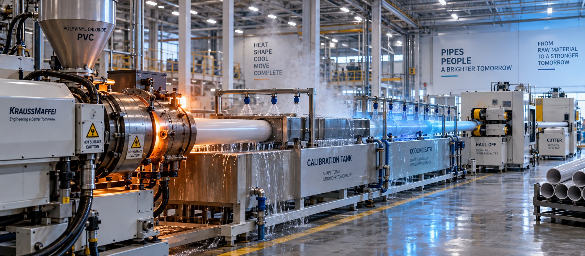
PVC Pipe Making Machine: What No Supplier Will Tell You First
Oct 21, 2026
Learn what a PVC pipe making machine really includes, how each component works, extruder types compared, maintenance schedules, defect fixes, and buying tips.
Read Article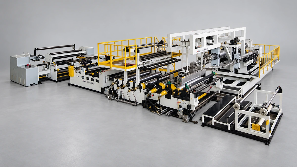
What Your Film Extrusion Machine Datasheet Won't Tell You
Oct 20, 2026
Film extrusion machine guide covering blown vs cast processes, multilayer configurations, screw specs, resin selection, and supplier evaluation for production engineers.
Read Article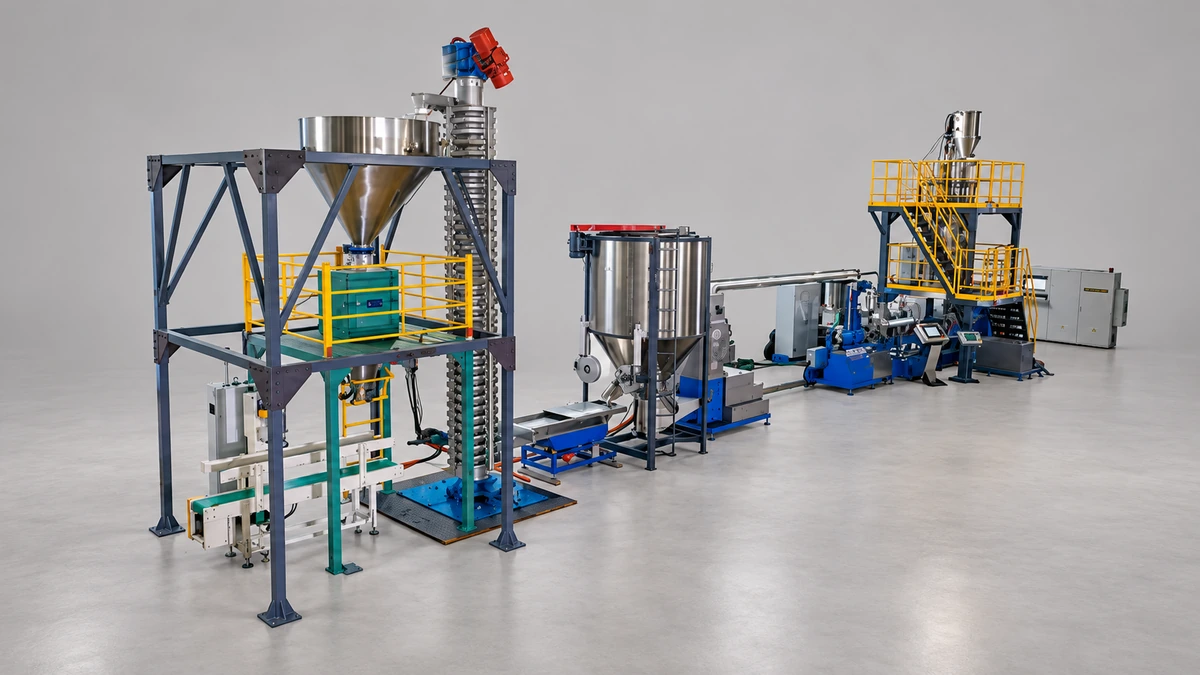
Raw Scrap to Perfect Pellets: Plastic Pelletizing Machine Guide
Oct 19, 2026
Learn how a plastic pelletizing machine converts scrap into uniform pellets. Covers cutting methods, extruder types, quality control, costs, and maintenance.
Read ArticleLooking for something else?
Search by material, symptom or product and jump straight to the relevant page.
These are navigation suggestions based on keyword matching — not a quotation, not a delivery commitment, and not a substitute for engineering review. Final specification is confirmed by our engineers against your drawings and processed material.
Need help with screw barrel selection?
Share your machine model, processed material and application. Our team can help with pricing and technical support.