

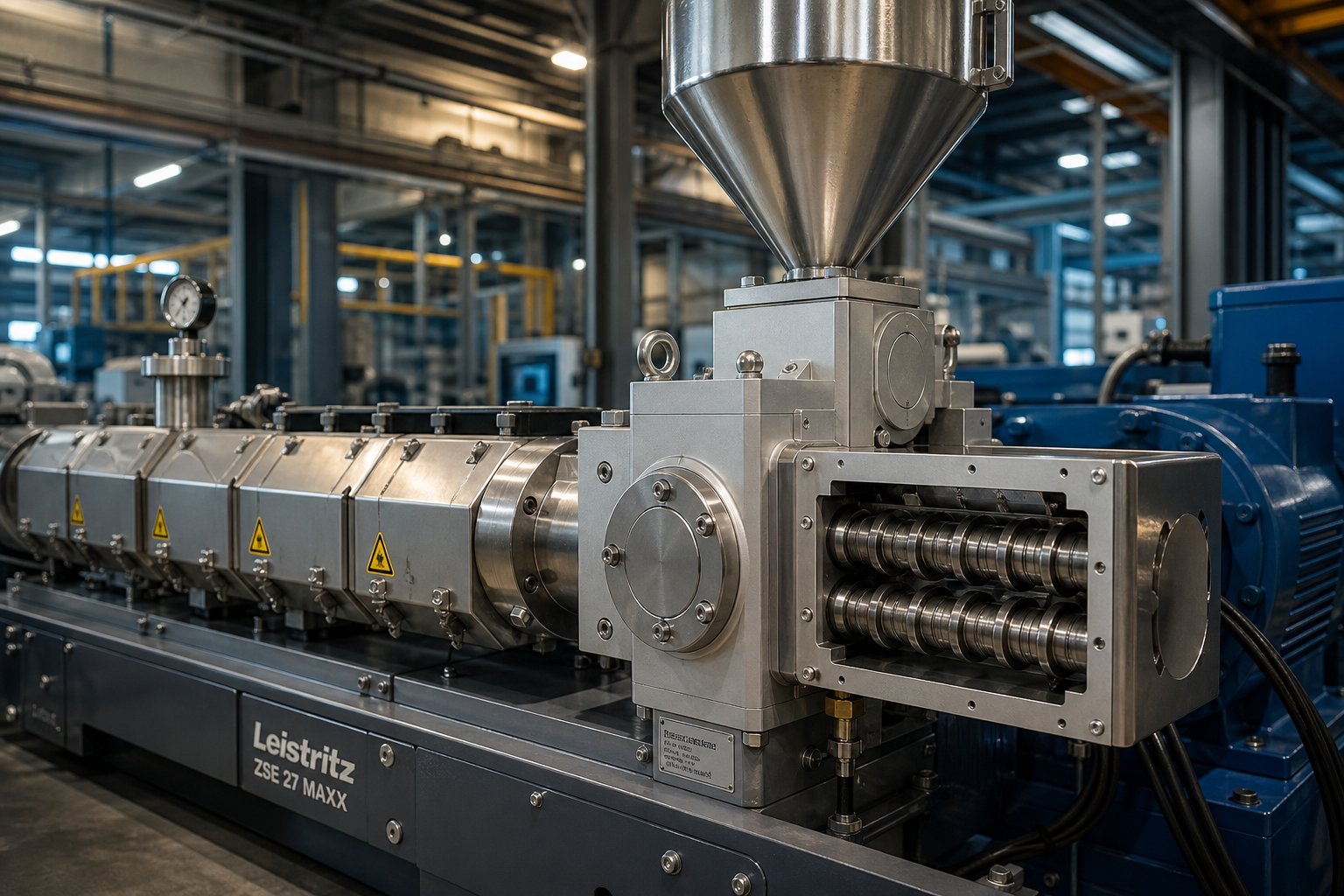
What a Side Feeder Twin Screw Extruder Actually Does
Imagine you are running a compounding line and need to add glass fiber into a polymer melt without shredding those fibers to dust. Dumping everything into the main hopper sounds simple, but it creates problems that most operators only discover after scrapping product. That is exactly where a side feeder twin screw extruder comes in — and understanding how it works is the first step toward avoiding costly mistakes.
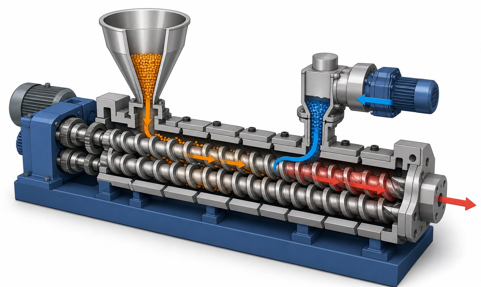
A side feeder is a secondary co-rotating, intermeshing twin screw device mounted downstream on the barrel of a main twin screw extruder. Its purpose is to introduce additional materials — such as fillers, fibers, or sensitive additives — directly into the polymer melt stream after the primary resin has already been melted or partially melted, bypassing the high-shear melting zone entirely.
This is fundamentally different from simply feeding all ingredients through the main hopper at once. A side feeder gives you precise control over where and when secondary materials enter the process, which directly affects product quality, fiber length retention, and additive integrity.
Defining the Side Feeder in Twin Screw Extrusion
So how does a side feeder work on an extruder in practical terms? The device bolts to the main extruder barrel at a specific L/D position — typically at a 90-degree angle — and interfaces through a machined opening in a dedicated barrel segment. Inside, a pair of co-rotating intermeshing screws act as a conveying auger that pushes material into the main extruder's melt stream. As described in a technical review published in AAPS PharmSciTech, this side stuffer "pushes material into the process melt stream to allow for avoidance of the high shear region associated with melting and also reducing residence time exposure for heat-sensitive materials."
The main extruder's screw configuration at that barrel position uses open conveying elements with wide pitch, creating partially filled channels that accept the incoming material without causing pressure buildup or blockage. You'll notice that the side feeder essentially works as a dedicated delivery system — it does not melt or mix the material itself but ensures reliable conveyance into the main process.
Core Components of a Side Feeder System
Every side feeder system relies on a handful of essential components working in coordination. Here is what makes up a typical setup:
- Twin-screw feeding element — the co-rotating intermeshing screw pair that conveys material from the inlet into the main extruder barrel
- Feed barrel or housing — the enclosure surrounding the twin screws, providing structural support and guiding material flow
- Drive motor and gearbox — powers the side feeder screws independently from the main extruder, allowing separate speed control
- Hopper or gravimetric feeder — mounted above the side feeder inlet to meter material at a controlled rate
- Barrel adapter — the machined interface piece connecting the side feeder housing to the main extruder barrel segment
These twin screw extruder side feeder components are standard equipment on modern compounding lines, yet they remain surprisingly misunderstood — especially by operators newer to twin screw extrusion. Many assume the side feeder is just an optional accessory. In reality, it is a core process component that determines whether fillers disperse properly, fibers survive intact, and heat-sensitive additives reach the die without degradation.
The real complexity, though, is not in the hardware itself. It is in understanding when side feeding is actually necessary — and when the main hopper can handle the job alone.
When to Choose Side Feeding Over Main Hopper Feeding
Here is a question that trips up more operators than you might expect: does every additive, filler, or reinforcement actually need a side feeder, or are you overcomplicating the process? The answer is not always obvious, and getting it wrong goes in both directions — some operators side-feed materials that would perform perfectly well through the main hopper, adding unnecessary equipment cost. Others force everything through the main throat and wonder why their glass-fiber-reinforced parts have the mechanical properties of wet cardboard.
A clear decision framework eliminates the guesswork. The key variable is whether a material can tolerate the full thermal and mechanical history of the extruder — from feed throat to die — or whether it needs to skip part of that journey.
Main Hopper Feeding and Its Limitations
Main hopper feeding is the simplest configuration. All ingredients — resin, additives, fillers — enter the extruder together at the feed throat before any melting takes place. This approach works well for straightforward formulations: simple polymer blends, compounds with low filler loadings, or recipes where every ingredient is heat-stable and free-flowing.
The trouble starts when any of these conditions break down. Consider three common failure modes:
- Shear-sensitive additives degrade. Organic pigments, certain antioxidants, and functional additives that enter at the main hopper pass through the entire melting and mixing zone. That extended exposure to high temperature and intense shear can cause color shifts, reduced effectiveness, or outright decomposition.
- Fragile fillers break apart. Chopped glass fibers fed through the main throat get ground down by unmelted resin pellets and aggressive kneading elements in the melting section. The result is dramatically shorter fiber lengths — and mechanical properties that fall well below specification.
- Low-bulk-density materials choke the feed zone. Fluffy powders, recycled film flake, or expanded microspheres occupy enormous volume relative to their mass. Forcing them through the main hopper causes bridging, inconsistent feed rates, and starved sections downstream.
When you are running a heat-stable, free-flowing recipe at moderate filler levels, main hopper feeding keeps things simple and cost-effective. The moment any ingredient is fragile, heat-sensitive, or volumetrically challenging, that simplicity becomes a liability.
When Side Feeding Becomes Essential
Side feeding earns its place when a material needs to bypass the early, high-shear, high-temperature portion of the screw. There are four scenarios where downstream feeding is not just helpful — it is essential.
Glass fiber and reinforcement preservation. This is the single most common reason to use a side feeder on a twin screw extruder. Chopped glass strands, carbon fiber, and natural fiber reinforcements must enter the barrel after the polymer is fully molten. The fibers wet out and disperse in the melt with far less length attrition than they would experience if subjected to the melting zone's kneading blocks. As one engineering analysis notes, feeding fibers through the main throat "subjects them to the entire melting section — where they get chopped short by the unmelted resin and aggressive melting elements." The mechanical properties of the final part depend directly on preserving that fiber length.
High mineral filler loadings. Formulations calling for 40%, 60%, or even 80% calcium carbonate, talc, or barium sulfate simply cannot be pushed through the main feed throat alone. The sheer volume of powder overwhelms the feed zone's conveying capacity, causes bridging at the hopper, and destabilizes the melting process. Introducing the filler downstream — where the melt can immediately wet and carry it — bypasses these problems entirely.
Heat-sensitive and shear-sensitive additives. Some ingredients lose their functionality if exposed to the full barrel residence time. Blowing agents that activate prematurely, organic colorants that degrade, or reactive additives that cross-link too early all benefit from late-stage introduction through a side feeder. They enter the process late, spend less time at elevated temperatures, and encounter lower shear stresses because the melt viscosity has already dropped by that point in the barrel.
Recycled flake and regrind with poor flow characteristics. Post-consumer recycled film flake is notoriously difficult to feed — it is lightweight, irregularly shaped, and tangles easily. A side feeder designed for low-bulk-density materials can compact and convey this feedstock into the melt stream reliably, which is why the plastics recycling industry has driven significant innovation in downstream feeding technology.
Split Feeding as a Hybrid Strategy
What if you need a high filler loading but also want strong dispersion throughout the compound? Split feeding offers a middle path. In this approach, the same filler is divided between the main hopper and a downstream side feeder. A portion enters with the resin at the feed throat — where it gets intensive mixing during the melting process — while the remainder is introduced downstream to reach the target loading without overwhelming the front end of the extruder.
Split feeding is particularly common in heavily filled systems where the total filler content exceeds what either the main hopper or a single side feeder can handle alone. It balances dispersion quality against volumetric throughput, though it adds process complexity because two feed streams for the same material must be coordinated.
The following table puts all three strategies side by side so you can match the right feeding approach to your formulation:
| Criteria | Main Hopper Feeding | Side Feeding (Downstream) | Split Feeding (Hybrid) |
|---|---|---|---|
| Filler Loading Capacity | Low to moderate — limited by feed zone volume | High — bypasses feed throat entirely | Very high — distributes load across two feed points |
| Fiber Length Preservation | Poor — fibers pass through melting zone | Excellent — fibers enter molten polymer directly | Not typically used for fiber applications |
| Heat-Sensitive Additive Suitability | Poor — full thermal and shear exposure | Good — reduced residence time and shear | Moderate — main hopper portion still sees full history |
| Filler Dispersion Quality | Good at low loadings — maximum mixing length | Good — relies on downstream mixing elements | Excellent — combines early and late-stage mixing |
| System Complexity | Lowest — single feed point | Moderate — requires side feeder hardware and barrel port | Highest — two coordinated feed streams for one material |
| Best Suited For | Simple blends, low-fill compounds, heat-stable recipes | Glass fiber, high filler, sensitive additives, recycled flake | Very high filler loadings requiring maximum dispersion |
The decision ultimately comes down to one question: does the material benefit from entering the melt stream late? If it is a fragile fiber, a heavy filler load, a heat-sensitive additive, or a difficult-to-feed recyclate, the answer is yes. If every ingredient in your recipe is heat-stable, free-flowing, and used at moderate loadings, main hopper feeding keeps the process lean and the equipment list short.
Choosing the right feeding strategy, however, is only half the equation. The real performance gains — and the most common operator mistakes — show up in how the side feeder interacts with the main extruder's starve-fed operation, a relationship governed by screw fill levels, free volume, and feed-rate balancing that most training programs never fully explain.
How Starve Feeding Principles Drive Side Feeder Performance
Here is where most operators get tripped up — and where training programs fall short. You can pick the perfect feeding strategy, install the right hardware, and still run into torque spikes, material backup, or inconsistent mixing. Why? Because the side feeder does not operate in isolation. It is locked into a dynamic relationship with the main extruder, and that relationship is governed by a concept called starve feeding. If you do not understand how starve-fed operation works, you are essentially flying blind every time you adjust a process parameter.
Understanding Starve-Fed Operation in Twin Screw Extruders
If you have spent time around single screw extruders, you will need to unlearn a fundamental assumption. On a single screw machine, the screw acts as both a pump and a conveyor — material fills the channels completely, and throughput is controlled by screw speed. Turn the screw faster, push more material through. Simple.
Co-rotating twin screw extruders do not work that way. They operate in starve-fed mode, meaning the screw channels are never fully filled along their entire length. The screws spin at a set speed, but throughput is dictated by the upstream feeders — gravimetric or volumetric devices that meter material into the barrel at a controlled rate. The screws simply convey whatever the feeders deliver. This distinction matters enormously because it means there is always open volume — partially empty screw channels — somewhere inside the barrel.
Why does this matter for side feeding? Imagine trying to pour water into a pipe that is already running full. The water has nowhere to go, and it backs up. The same principle applies inside the extruder barrel. At the point where the side feeder introduces filler, fiber, or any secondary material, the main extruder's screw channels must have available free volume to accept that incoming stream. If the channels are too full at that barrel position, the new material cannot enter cleanly. Pressure spikes, backup into the side feeder barrel, and torque instability follow almost immediately.
This is why starve-fed twin screw extruder side feeder operation is fundamentally a question of capacity management — not just speed settings or feed rates in isolation.
How the Side Feeder Maintains Starve-Fed Conditions
The interplay between the side feeder and the main extruder is a balancing act that plays out in real time. At the side feed zone, the main extruder's screw configuration typically uses conveying elements with wide pitch — often around 2D (two times the screw diameter) — to create maximum open channel volume. As one screw design guide recommends, large lead conveying screw elements in the side feeding zone ensure sufficient free volume to accept the incoming material without resistance.
The side feeder's job is straightforward: deliver material at a rate the main extruder can convey away from that zone. Two failure modes emerge when this balance breaks:
- Overfilling the feed zone. When the side feeder pushes material in faster than the main extruder can carry it downstream, the zone becomes fully filled. Material backs up into the side feeder barrel itself, causing torque spikes in the side feeder drive, potential blockage at the barrel interface, and in severe cases, material exiting backward through the side feeder hopper. You will typically see erratic torque readings on both the side feeder and main extruder motors before a full blockage occurs.
- Underfilling the feed zone. When the side feeder delivers too little material, throughput drops below target and mixing uniformity suffers. The downstream kneading and mixing elements receive an inconsistent material stream, leading to poor filler dispersion, uneven fiber distribution, or concentration gradients in the final product. Less dramatic than a blockage, but just as damaging to product quality over a production run.
The practical consequence is that the side feeder free volume capacity at the extruder barrel dictates the ceiling on how much material you can introduce at that position. Exceed it, and the process destabilizes. Fall well below it, and you leave throughput and quality on the table.
Air entrapment adds another layer of complexity. As Xtrutech's engineering analysis explains, air circulating around the screws takes up space within the extruder and creates unstable torque — the mechanical equivalent of driving in constant stop-and-start traffic. Low-bulk-density fillers carry significant volumes of entrained air into the barrel, effectively reducing the available free volume for solid material. This means the actual capacity of the side feed zone is always less than the theoretical geometric volume of the screw channels.
Balancing Feed Rate and Screw Design
Getting the feed rate right is only half the equation. The screw element configuration in the side feed zone of the extruder — and immediately downstream of it — plays an equally critical role.
At the barrel port where material enters, wide-pitch conveying elements create the open volume needed to receive the incoming stream. But those conveying elements cannot extend indefinitely. Further downstream, the screw configuration transitions to mixing or kneading elements that disperse and distribute the newly introduced material into the polymer melt. This transition must be carefully positioned: too close to the feed port and the restrictive mixing elements choke material intake; too far downstream and the filler or fiber travels a long distance without being incorporated into the melt, risking poor wetting and segregation.
Think of it as a two-step handoff. The conveying elements accept and move material away from the feed zone. The downstream mixing elements then do the work of blending that material into the melt. The distance between these two stages — and the geometry of the elements used — must match the material type, filler loading, and target throughput rate.
For operators troubleshooting how to prevent side feeder backup on a twin screw extruder, this screw element layout is the first place to look. A common mistake is running aggressive kneading blocks too close to the side feed opening, which creates a high-pressure region that resists incoming material. Replacing those elements with additional conveying sections — or simply increasing the pitch of existing conveying elements — often resolves chronic backup issues without any change to feed rates or screw speeds.
The side feeder delivery rate must never exceed the main extruder's free volume capacity at the feed zone. Violating this principle is the single most common cause of side feeder blockages, torque spikes, and inconsistent filler incorporation in twin screw compounding.
This principle sounds straightforward on paper, but in practice it forces operators to think about the process as a coupled system. The side feeder speed, the main extruder screw speed, the total throughput, and the screw element geometry at the feed zone all interact simultaneously. Adjusting one variable shifts the balance for all the others — a dynamic that becomes especially challenging when processing materials with variable bulk density, moisture content, or particle size distribution.
That material variability is precisely where the next layer of complexity lives. Different filler types, fiber formats, and recycled feedstocks each bring unique handling challenges to the side feeder — challenges that demand material-specific strategies rather than one-size-fits-all operating rules.
Handling Difficult Materials Through Side Feeding
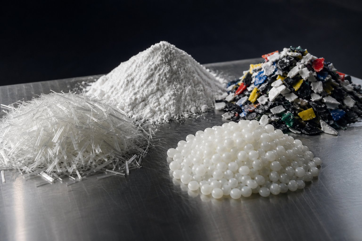
Every material that enters a side feeder brings its own set of headaches. Glass fiber behaves nothing like calcium carbonate, which behaves nothing like recycled film flake, which behaves nothing like a sticky wax-based additive. Yet operators frequently apply the same screw speeds, the same temperature settings, and the same maintenance schedules regardless of what they are feeding. That is a fast track to screw wear, inconsistent product, and unplanned downtime.
The reality is that material-specific strategies separate smooth-running lines from chronic troubleshooters. Here is what each major material category demands — and where things go wrong most often.
Feeding Glass Fiber and Abrasive Fillers
Glass fiber is arguably the single most common material introduced through a side feeder. The entire purpose of downstream feeding in this application is straightforward: introduce chopped glass strands into a fully molten polymer so the fibers wet out and distribute evenly while retaining as much of their original length as possible. Fiber length directly controls mechanical performance in the finished part — tensile strength, impact resistance, and stiffness all degrade when fibers get ground short.
Effective side feeding glass fiber on a twin screw extruder starts with screw element selection in the main barrel. Wide-pitch conveying elements at the feed zone pull fibers gently into the melt without crushing them. Downstream, distributive mixing elements — rather than aggressive kneading blocks — spread fibers through the polymer matrix with minimal breakage. Think of it as the difference between folding egg whites into batter versus beating them with a whisk. The gentler approach preserves structure.
Abrasion, however, is the hidden cost of processing glass fiber and similar hard fillers. Glass strands, calcium carbonate particles, wollastonite needles, and glass beads are all significantly harder than standard nitrided steel. Over hundreds of operating hours, they erode screw flight tips, barrel bore surfaces, and the side feeder screws themselves. The wear pattern is predictable — flight outer diameters shrink, clearances between screw and barrel increase, and conveying efficiency drops. You will notice the first sign as a gradual decline in feed rate at constant screw speed.
For these abrasive filler applications, bimetallic barrel liners and tool-steel or powder-metallurgy screw elements are standard recommendations. The upfront cost is higher, but the extended service life and consistent conveying performance more than justify the investment — especially on lines running 24/7 with filler loadings above 30%.
Low-Bulk-Density Materials and Recycled Flake
Imagine trying to push a handful of cotton balls through a straw. That is roughly the challenge a side feeder faces when handling low-bulk-density materials like recycled film flake, expanded microspheres, or wood flour. These materials occupy enormous volume relative to their mass, flow poorly, and trap large quantities of air between particles. Standard side feeders can struggle to compact and convey them at rates that keep the main extruder productive.
The volumetric bottleneck is the core issue. A side feeder's conveying capacity is defined by its screw channel volume multiplied by the material's bulk density. When bulk density drops below roughly 200 kg/m³, conventional side feeders simply cannot deliver enough mass per revolution to keep up with the main extruder's capacity. The result is a line that runs far below its rated throughput — not because the extruder is limited, but because the feeding system cannot supply enough material.
This is precisely the problem that Coperion's ZS-B MEGAfeed technology was engineered to solve. By using a larger-diameter side feeder with optimized screw geometry, the MEGAfeed dramatically increases the volumetric intake capacity for lightweight recyclate. The throughput gains are striking: when recycling PA fibers with a bulk density of roughly 40 to 50 kg/m³, throughputs jumped from 70 kg/h with conventional equipment to approximately 1,000 kg/h using the MEGAfeed — a fourteenfold increase. Carbon fiber recyclate saw even more dramatic improvements, climbing from 50 kg/h to 2,500 kg/h. Post-consumer recycled flakes went from 50 kg/h to 700 kg/h.
For operators running a side feeder for recycled plastic flake extrusion without access to oversized feeding technology, practical workarounds include pre-densifying or agglomerating the flake before feeding, using crammer-style forced feeders above the side feeder inlet, and ensuring the side feeder hopper design prevents bridging through steep wall angles and possibly vibration assists. Even so, low-bulk-density filler side feeder challenges remain among the toughest problems in compounding — and one of the fastest-growing, given the plastics recycling industry's push toward processing post-consumer waste streams.
Sticky Additives and Liquid Feeds
Not every difficult material is hard or fluffy. Some of the most frustrating side-feeding problems involve sticky or tacky additives — waxes, certain processing aids, rubber-modified masterbatch pellets with surface bloom, or hygroscopic powders that clump in humid environments. These materials adhere to screw flights, coat barrel walls, and gradually build up until conveyance slows or stops entirely.
Cooling jackets on the side feeder barrel are the first line of defense. By keeping the barrel temperature well below the material's softening or tack point, you prevent the additive from smearing across metal surfaces. Optimized screw geometry helps too — polished screw surfaces with reduced root diameter and minimal stagnation zones give sticky materials fewer places to accumulate. Some operators also apply surface coatings or treatments to screw elements to reduce adhesion, though results vary by material chemistry.
Liquid additives — oils, plasticizers, liquid colorants — are a different category altogether. These are typically injected directly into the barrel through dedicated injection ports using gear pumps or piston metering systems, not conveyed through a twin screw side feeder. However, viscous pastes or semi-solid concentrates that do not flow well enough for pump injection occasionally use modified side feeders with heated barrels and specialized screw profiles to achieve reliable conveyance.
To put the full landscape in perspective, here are the major material categories and the primary challenges each presents during side feeding:
- Glass fiber and mineral reinforcements — fiber length attrition, accelerated abrasive filler wear on side feeder screw elements and barrel liners
- High-loading mineral fillers (CaCO₃, talc, BaSO₄) — volumetric feed limitations, dust generation, abrasion on conveying surfaces
- Recycled film flake and post-consumer waste — extremely low bulk density, air entrapment, bridging, inconsistent particle geometry
- Wood flour and natural fibers — moisture sensitivity, low bulk density, tendency to char at elevated barrel temperatures
- Expanded microspheres — fragile structure that collapses under excessive compaction or shear, very low bulk density
- Sticky waxes and tacky additives — surface adhesion to screws and barrel, buildup causing flow restriction, temperature sensitivity
- Viscous pastes and semi-solid concentrates — poor flowability, potential for channel blockage, may require heated side feeder barrel
Each of these material types responds differently to changes in screw speed, barrel temperature, and feed rate — which is exactly why dialing in the right speed ratio between the side feeder and the main extruder is so critical. Getting that ratio wrong amplifies every material-specific challenge listed above, turning manageable feeding difficulties into full-blown production stoppages.
Optimizing Speed Ratios Between Side Feeder and Main Extruder
Ask ten operators how they set their side feeder screw speed and you will likely get ten different answers — most of them based on gut feeling, inherited machine settings from a previous shift, or trial-and-error that was never formally documented. This is one of the most consequential process variables on a compounding line, yet side feeder speed ratio optimization on a twin screw extruder remains almost entirely absent from equipment manuals, training courses, and industry literature. The result is that operators either run too conservatively and leave throughput on the table, or push too aggressively and trigger the exact torque spikes and blockages that derail production.
The speed ratio is not a single magic number you look up in a chart. It is a dynamic variable that interacts with everything else on the line — and understanding those interactions is what separates confident process control from reactive troubleshooting.
Why the Speed Ratio Matters
The side feeder screw speed relative to the main extruder screw speed directly governs how efficiently material moves from the side feeder barrel into the main melt stream. Picture a revolving door at a building entrance. If the door spins too slowly, people pile up in the lobby. If it spins too fast, it shoves people into a crowded hallway where there is no room to move. The side feeder works on the same principle — it must deliver material at precisely the rate the main extruder can absorb and convey downstream.
When the speed ratio is too low, the side feeder cannot convey material fast enough. Powder, fiber, or filler accumulates inside the side feeder barrel, backs up into the hopper, and eventually bridges or floods the inlet. You will see this as erratic gravimetric feeder readings, declining throughput, and inconsistent filler concentration in the finished product. In severe cases, the side feeder torque climbs steadily as compacted material resists the screw rotation.
When the speed ratio is too high, the opposite problem emerges. The side feeder rams material into the main extruder's feed zone faster than the main screws can carry it away. The screw channels overfill, local pressure spikes develop, and material can be pushed upstream in the barrel — against the intended flow direction. Main extruder torque becomes unstable, melt pressure at the die fluctuates, and in worst-case scenarios the overfilled zone creates a plug that stalls the entire process. As the screw speed optimization guidance from MPMtek emphasizes, making small incremental adjustments rather than large leaps is critical because overshooting in either direction can quickly destabilize the system.
The takeaway is that speed ratio is not about the side feeder alone — it is about the relationship between two machines that share a common process stream. Getting it right requires monitoring both simultaneously.
Finding the Optimal Operating Window
So how do you actually set the side feeder screw speed on an extruder when there is no universal formula? The honest answer: empirically, guided by process data and a systematic approach.
Start with the target gravimetric feed rate for the downstream material. Your loss-in-weight feeder above the side feeder inlet should be set to deliver the exact mass flow required by the formulation. The side feeder screw speed is then adjusted until it can reliably convey that mass flow into the main barrel without accumulation or starvation. Here is a practical sequence most experienced operators follow:
- Set the gravimetric feeder to the target mass flow rate based on the recipe and total line throughput.
- Start the side feeder at a moderate speed — typically in the range that achieves steady conveyance without visible material backup at the inlet.
- Monitor four key indicators simultaneously: main extruder torque (percentage of maximum), melt pressure at the die, side feeder torque, and the gravimetric feeder's actual versus target feed rate.
- Increase side feeder speed incrementally if material accumulates in the side feeder barrel or the gravimetric feeder shows it cannot discharge at the target rate.
- Decrease side feeder speed if main extruder torque becomes erratic, die pressure swings beyond normal range, or visual inspection of the side feed port shows material backing into the barrel opening.
The optimal window depends on several interacting factors: material bulk density (lighter materials need higher screw speeds to move equivalent mass), filler loading level (higher loadings push more volume through the same port), main extruder free volume at the feed zone (determined by the screw element pitch and OD/ID ratio), and the screw element configuration in both the side feeder and the main barrel. As Leistritz's technical analysis of boundary conditions explains, the free volume available in the TSE — characterized by the cc/diameter value and OD/ID ratio — directly determines how much material can be accepted at any given barrel position. A volume-limited process hits its ceiling when the screw channels physically cannot accommodate more incoming material, regardless of how fast the side feeder runs.
This is why side feeder torque monitoring in twin screw compounding is not optional — it is your primary early-warning system. Rising side feeder torque at constant speed signals material accumulation, while dropping torque at constant speed may indicate the upstream gravimetric feeder is not keeping up. Either condition means the speed ratio needs adjustment before product quality suffers.
One critical point worth emphasizing: there is no universal speed ratio that works across materials and formulations. A line running 40% glass fiber in nylon will require a completely different ratio than the same extruder compounding 70% calcium carbonate in polypropylene. Even switching between two grades of the same filler — say, a coarse-ground versus fine-ground CaCO₃ — can shift the optimal window because bulk density and flow characteristics change. Every new formulation deserves its own speed ratio validation, documented and stored for future reference.
System-Level Interaction of Process Parameters
Here is where process control on a side feeder twin screw extruder becomes genuinely complex — and genuinely interesting. The side feeder speed is not an independent dial you turn in isolation. It is coupled to the main extruder screw speed, the total throughput rate, the barrel temperature profile, and the screw element geometry at the feed zone. Change any one of these, and the optimal side feeder speed shifts along with it.
Consider a concrete example. You are compounding a talc-filled polypropylene and want to increase total line throughput by 15%. Simply increasing the gravimetric feeder rate and the side feeder speed — without adjusting the main extruder — may overfill the feed zone because the main screws are not creating enough free volume to accept the additional material. The fix? Increase the main extruder screw speed proportionally. Higher main screw RPM moves material away from the side feed zone faster, opening up channel volume and restoring the starve-fed condition that keeps the process stable. But that higher RPM also increases shear rate and mechanical energy input, which raises melt temperature and may reduce residence time in downstream mixing zones. So you may need to adjust barrel temperature setpoints — perhaps lowering them slightly to compensate for the additional shear heating — and possibly re-evaluate whether the downstream kneading elements still provide adequate dispersion at the higher throughput.
This cascading effect is exactly what the process parameter interaction analysis describes: feed rate versus screw RPM, combined with screw design and temperature profile, collectively regulate the mass transfer and mixing properties of the process. You cannot optimize one variable without accounting for its impact on every other.
The following table maps these relationships clearly, showing how adjustments to each major process parameter ripple through the system:
| Parameter Adjusted | Effect on Fill Level at Side Feed Zone | Effect on Torque | Effect on Residence Time | Effect on Mixing Intensity |
|---|---|---|---|---|
| Increase side feeder speed (constant main screw speed) | Increases — more material enters the zone per unit time | Main extruder torque rises; side feeder torque may drop if material clears faster | Minimal direct effect — governed primarily by main screw speed | May improve distributive mixing if fill level in downstream kneading zones increases |
| Decrease side feeder speed (constant main screw speed) | Decreases — less material enters the zone per unit time | Main extruder torque drops; side feeder torque may rise if material compacts | Minimal direct effect | May reduce mixing uniformity due to inconsistent filler delivery |
| Increase main screw speed (constant side feeder speed) | Decreases — material is conveyed away faster, opening free volume | Torque may decrease per unit throughput but total energy input rises | Decreases — material moves through barrel faster | Increases — higher shear rates in kneading zones, more extensional mixing |
| Increase total throughput (both feeders proportionally) | Increases — both feed zones receive more material | Rises — more material requires more energy to convey and mix | Decreases — higher flow rate at constant barrel length | Decreases if mixing zone fill approaches saturation — dispersive quality may suffer |
| Raise barrel temperature at side feed zone | Indirect effect — lower melt viscosity allows easier downstream conveyance | May decrease slightly as material flows more readily | Minimal direct effect | Dispersive mixing may decrease as lower viscosity reduces shear stress on filler particles |
The pattern is clear: every adjustment creates trade-offs. Increasing throughput demands higher main screw speeds to maintain free volume, but higher screw speeds reduce residence time and increase shear — potentially degrading heat-sensitive components or shortening fiber lengths. Raising barrel temperatures eases conveyance but can reduce the viscosity-dependent shear forces needed for effective filler dispersion.
For operators managing process parameter interaction between a side feeder and the main extruder day to day, the practical lesson is this: document every successful operating condition as a complete parameter set — side feeder speed, main screw RPM, all feeder rates, barrel temperature profile, and the resulting torque and pressure values. When you change formulations or scale throughput, use that documented baseline as a starting point and adjust one variable at a time while watching how the others respond. Jumping straight to a new set of parameters without understanding the coupled relationships is how operators end up chasing problems that multiply with every correction.
Speed ratio optimization keeps the material flowing into the barrel. But all that filler, fiber, and powder carries something else along with it — air. And trapped air inside the melt creates an entirely different category of product defects that no amount of speed tuning can fix on its own.
Managing Air Entrapment and Degassing in Side-Fed Systems
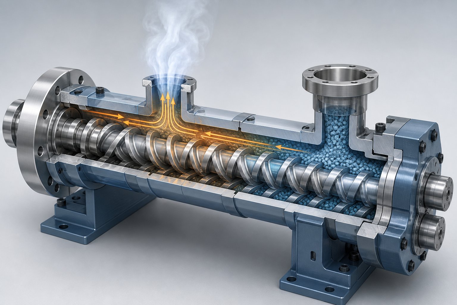
Every kilogram of dry filler, powder, or fiber that enters through a side feeder carries a hidden passenger: air. And the lighter and fluffier the material, the more air hitches a ride into the barrel. This is one of the most overlooked causes of product defects in twin screw compounding, yet degassing strategy for twin screw extruder side feeder venting rarely gets the attention it deserves in operator training or equipment manuals. If you are not actively managing entrained air, you are baking voids, surface blemishes, and porosity directly into your product.
Why Side Feeding Introduces Air Entrapment
Think about what happens physically when a mineral filler like calcium carbonate or talc enters the main extruder through a side feeder. The powder particles do not pack together perfectly — each particle is surrounded by tiny pockets of air. The lower the bulk density, the more air is trapped between particles. A fine-ground talc at 300 kg/m³ bulk density is roughly 80% air by volume. Recycled film flake at 50 kg/m³ can be over 95% air.
All of that air gets pushed into the extruder barrel alongside the solid material. Once inside, it has to go somewhere. If it stays trapped in the melt, it creates voids, porosity, and surface defects in the final pellet or part. Trapped air also reduces the effective barrel volume available for mixing, which means the kneading elements downstream cannot do their job properly. The result is a compound that looks acceptable at the pelletizer but fails quality checks downstream — or worse, causes rejects in the customer's injection molding or film extrusion process.
As CPM Century Extrusion's technical analysis explains, atmospheric vents near side feeders are specifically designed to release the air that enters the machine with powders. When the vent open area is too small relative to the volume of air that must be removed, the resulting high exit velocity carries fines and powder out of the vent — creating a housekeeping nightmare on top of a quality problem. The challenge of air entrapment during side feeding of filler powder into an extruder grows proportionally with filler loading and inversely with bulk density. Lines running 70-80% mineral filler through multiple side feeders face truly enormous volumes of displaced air.
Upstream and Downstream Venting Strategies
Effective degassing in a side-fed system requires venting on both sides of the feed port — upstream and downstream — to give entrained air a clear escape path in each direction. Relying on a single vent is one of the most common mistakes operators make.
Upstream (back) venting places an atmospheric vent port between the main feed hopper and the side feed port. When material enters from the side feeder, it displaces air in the screw channels. Some of that air naturally travels backward along the partially filled conveying section toward the feed throat. An upstream atmospheric vent provides a low-resistance exit point for this backflow, preventing air from building pressure in the barrel. Detailed screw configuration studies show that for air to vent effectively through both back and front vents, the screws must be axially open — meaning partially filled — in the region between the vents. Fully filled screw channels block airflow and trap gases inside the melt.
Downstream (front) venting uses either an atmospheric vent or a vacuum vent positioned after the mixing or incorporation zone. By this point, the filler has been worked into the polymer melt, and residual air bubbles plus any moisture vapor need to be pulled out before the material reaches the die. Vacuum vents are particularly effective here because they provide an additional driving force for mass transfer — pulling volatiles out of thin melt films exposed in partially filled screw channels. Most compounding lines running side-fed formulations use both an atmospheric back vent near the side feeder and a vacuum vent further downstream.
The barrel configuration must dedicate specific segments to each vent. These venting barrels feature open ports on top, and the screw elements beneath them are always conveying elements — never kneading blocks or restrictive mixing elements. Why? Because conveying elements maintain a low degree of fill in the screw channels, preventing melt from rising up and escaping through the vent opening. If a kneading block sits directly under a vent, the increased fill level and local pressure will push material right out the port.
For highly filled systems, a single back vent and a single vacuum vent may not be enough. As the CPM Century Extrusion venting guide notes, side feeding of low-bulk-density fillers at high loadings — up to 80% — and high productivity requires multiple atmospheric vents to facilitate removal of large volumes of air from the barrel. Some production lines feature two or even three atmospheric vents bracketing the side feed zone, plus a downstream vacuum vent, to handle the sheer volume of displaced gas.
Vent Port Design Considerations for Side-Fed Systems
Here is a practical reality that catches many operators off guard during line design or retrofit: every vent port you add requires a dedicated barrel segment. That means a side-fed extruder configuration with proper venting uses more barrel sections than a non-side-fed setup. The back vent, the side feed barrel, the incorporation zone, and the downstream vent each occupy their own barrel position — and that adds up. Side-fed systems routinely require a longer overall L/D ratio simply to accommodate the venting barrels that effective degassing demands.
Vacuum vent placement on a side feeder compounding line deserves particular attention. The vacuum vent must sit far enough downstream from the incorporation zone that the filler is fully wetted and dispersed into the melt. If residual unincorporated powder reaches the vacuum vent, it gets sucked out of the barrel — fouling the vacuum system and reducing filler content in the final product. At the same time, the vacuum vent must be far enough upstream from the die that no melt backup from discharge pressure reaches the vent opening. As the CPM Century technical resource explains, when screen or die pressure increases, the backup length — the length of filled screw needed to develop discharge pressure — grows until it reaches the vent opening, flooding it with melt. A melt pump installed between the extruder and the die can decouple these two zones, keeping vacuum vent operation stable even at high throughput rates.
One more piece of hardware deserves mention: the vent stuffer. When processing low-bulk-density or fluffy materials — recycled flake, wood flour, expanded fillers — standard atmospheric vents can become problematic. The high velocity of escaping air carries fine particles out of the barrel, creating dust, material loss, and contamination. A vent stuffer is a small co-rotating twin screw device mounted directly onto the vent port opening. Its screws rotate to physically prevent material from exiting through the vent while still allowing air and vapor to travel axially along the stuffer's screw channels and escape. Vent stuffers in side-fed twin screw extrusion are particularly common on recycling lines where the incoming feedstock is lightweight and irregularly shaped. They can be mounted on the top or side of the barrel, and some specialty materials — those that tend to foam or expand under vacuum — can only be processed under vacuum venting by using vent stuffers to contain the melt.
Proper venting is what stands between a clean, void-free compound and a product full of hidden defects. But designing the right venting layout means understanding your barrel configuration in detail — how many segments you need, where the side feeder mounts, and whether your existing extruder has the physical length and barrel openings to accommodate everything. That question of sizing and configuration is exactly where operators planning a new side feeder installation or retrofitting an existing line need to look next.
Side Feeder Sizing and Retrofitting an Existing Extruder
Whether you are specifying a side feeder for a brand-new compounding line or trying to add downstream feeding capability to equipment that has been running for years, one question dominates the conversation: how big should this thing be? Get the sizing wrong and you either bottleneck your entire throughput or spend money on capacity you will never use. And if you are retrofitting, a second question is just as pressing: can your existing barrel and screw configuration even accept a side feeder — or does the whole layout need reworking?
These are practical, high-stakes decisions that most equipment manuals gloss over with generic tables and catalog specs. The reality on the plant floor is messier — and more nuanced — than any datasheet suggests.
Matching Side Feeder Size to Main Extruder Diameter
Side feeders are always smaller than the main extruder they serve. That much is intuitive — the side feeder is a secondary conveying device, not a standalone processing machine. But how much smaller? And what drives the selection?
Common pairings in the compounding industry range from side feeders with screw diameters of approximately 25 mm matched to smaller lab or pilot-scale extruders, all the way up to 92 mm side feeders paired with large production machines. The general principle is proportional scaling: a larger main extruder processes more material per hour, which means more filler or fiber must be introduced per hour, which demands a larger side feeder to handle that volumetric flow.
The critical sizing variable is volumetric conveying capacity. A side feeder's screw diameter, channel depth, pitch, and rotational speed together determine how many cubic centimeters of material it can push into the main barrel per minute. That volumetric capacity must match the target filler feed rate — expressed in mass per hour — divided by the material's bulk density. Sounds simple in theory, but as one engineering analysis on side feeder sizing emphasizes, relying on a single catalog bulk density figure is a common mistake. Aerated, packed, and production-handled bulk densities can differ significantly — and the lowest value under real production conditions is what determines whether your side feeder keeps up or falls behind.
Here is where the sizing decision becomes a balancing act:
- An undersized side feeder becomes the throughput bottleneck for the entire line. The main extruder has capacity to spare, but the side feeder cannot deliver filler fast enough. You end up running the side feeder at maximum speed — often near its torque limit — which accelerates wear, increases noise, and leaves zero margin for recipe changes that require higher filler loadings. Every time you need to push 10% more calcium carbonate or glass fiber, the undersized feeder says no.
- An oversized side feeder solves the capacity problem but introduces others. The equipment cost, footprint, and energy consumption are all higher than necessary. More importantly, an oversized feeder running at very low screw speeds can meter inconsistently — especially with low-bulk-density materials that need a certain minimum screw speed to maintain steady conveyance. As the sizing analysis notes, a feeder running too empty often meters inconsistently, particularly with lightweight powders or flakes.
A practical target for side feeder screw diameter selection on a compounding line is to choose a size where normal production runs at 30% to 80% of the feeder's rated capacity. That range provides enough headroom for recipe variations and future throughput increases without forcing the feeder into the extremes of its operating envelope where stability degrades. If your current recipe requires 300 kg/h of filler through the side feeder, you want a unit that can comfortably handle 375 to 1,000 kg/h — not one rated at exactly 300 kg/h with no room to breathe.
One more consideration that often gets overlooked: the side feeder must also be physically compatible with the main extruder barrel. The barrel opening that accepts the side feeder has a fixed geometry dictated by the main extruder's screw diameter and barrel segment design. A side feeder that is technically the right volumetric size but whose discharge opening does not align with the barrel port will not bolt up cleanly. Always confirm mechanical interface compatibility — flange dimensions, port geometry, and mounting orientation — before finalizing the selection.
Retrofitting an Existing Twin Screw Extruder with a Side Feeder
What if your extruder was originally set up without a side feeder, and now your product mix demands one? Maybe you are moving into glass-fiber-reinforced compounds, scaling up filler loadings beyond what the main hopper can handle, or adding a recycled-flake feed stream to an existing line. Can you retrofit a side feeder onto an existing twin screw extruder, or does the whole machine need replacing?
The short answer: yes, retrofitting is usually feasible — but it is not as simple as bolting on a new device. Several conditions must be met for a successful upgrade.
Barrel segment with a side feed opening. The main extruder barrel must have a segment with a machined port at the correct L/D position for downstream feeding. Most modern modular barrel systems use segmented construction where individual barrel sections can be swapped. If your current configuration does not include a barrel segment designed for side feeding, you will need to replace one or more barrel sections with a side-feed-compatible segment. This is the most common side feeder barrel segment replacement requirement in retrofit projects — and it is often the single largest cost and lead-time item.
Compatible screw elements in the main extruder. The screw configuration at the side feed zone must use wide-pitch conveying elements that create sufficient free volume to accept the incoming material. If your existing screw layout has kneading blocks or restrictive mixing elements at the position where the side feeder will introduce material, those elements must be swapped out. This typically means reconfiguring the screw from the side feed zone through the downstream mixing section — not just changing one or two elements.
Mounting flange and mechanical support. The side feeder drive, gearbox, and barrel assembly have significant weight. The main extruder frame must provide a rigid mounting point that supports the side feeder without introducing vibration or misalignment. Some older extruder frames lack the structural provisions for a lateral load at the barrel midpoint, requiring fabrication of a support bracket or stand.
Drive and control integration. The side feeder needs its own motor, gearbox, and speed controller, which must be integrated into the line's overall control system. The gravimetric feeder above the side feeder inlet also requires a dedicated controller that communicates with the main line's supervisory system. On modern lines with PLC-based controls, this integration is straightforward. On older relay-logic or analog-controlled systems, the control upgrade can be a significant portion of the project scope.
Practical Constraints and Cost Considerations
Even when all the technical requirements check out, operators planning to retrofit a side feeder onto an existing twin screw extruder should budget for several practical realities that paper evaluations tend to understate.
Downtime is the most immediate concern. Swapping barrel segments, reconfiguring the screw layout, mounting the side feeder assembly, running electrical and control wiring, and performing initial commissioning tests all require the extruder to be offline. Depending on the complexity of the retrofit and the availability of components, this can range from a few days for a well-prepared project to several weeks if barrel segments or custom screw elements need to be manufactured to order.
Validation is the other time sink. Once the hardware is installed, you cannot simply resume production at full speed. The new feeding configuration requires validation runs to confirm that the side feeder delivers material at the target rate without backup, that the main extruder torque and melt pressure remain stable, that venting is adequate for the new material stream, and that the final product meets quality specifications. For regulated industries or demanding end-use applications, this validation phase can take longer than the physical installation.
Here is a concise checklist of the key requirements for a successful side feeder retrofit project:
- Confirm a barrel segment with a side feed port is available or can be sourced for your extruder model
- Verify that the side feed barrel position provides adequate L/D distance for downstream mixing and venting
- Redesign the main extruder screw configuration to include open conveying elements at the feed zone
- Check gearbox compatibility for the side feeder drive — torque rating, output speed range, and shaft orientation
- Ensure the extruder frame can structurally support the side feeder assembly without excessive deflection
- Plan for electrical and control system integration, including gravimetric feeder communication
- Allocate sufficient upstream or downstream barrel positions for any additional venting required by the new feed stream
- Budget for validation runs using target materials at planned production rates before returning to commercial production
- Identify and pre-order long-lead-time components — barrel segments, screw elements, adapter flanges — to minimize downtime during installation
The cost of a retrofit varies widely depending on extruder size, the number of barrel sections that need replacement, and whether control systems require upgrading. For a mid-size production extruder, expect the side feeder unit, barrel modifications, screw elements, and installation to represent a meaningful capital investment — but one that is typically a fraction of the cost of purchasing a new extruder with side feeding built in from the factory.
Sizing and installing the side feeder correctly gets material into the barrel. Keeping it running reliably over thousands of production hours, however, introduces an entirely different set of challenges — ones that center on wear patterns, preventive maintenance schedules, and the sometimes-frustrating reality of sourcing replacement parts for equipment that runs hard, day after day.
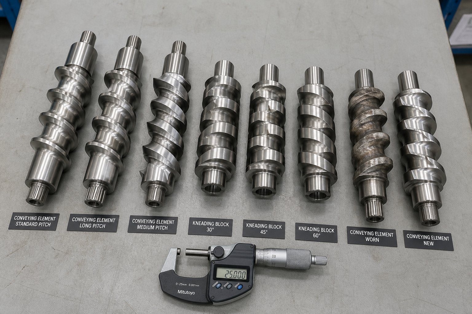
Maintenance Strategies and Sourcing Replacement Parts
A side feeder that runs flawlessly during commissioning will not stay that way forever. Every hour of operation — every kilogram of glass fiber, every ton of calcium carbonate, every batch of mineral-loaded compound — grinds away at the metal surfaces that keep the system performing to spec. The irony is that side feeders often process the most abrasive materials on the entire compounding line, yet they receive the least maintenance attention. Operators focus on the main extruder's screws and barrels, the die, the pelletizer — and treat the side feeder as a secondary device that can wait. That oversight is how small, manageable wear progresses into unplanned shutdowns, out-of-spec product, and emergency parts orders at premium pricing.
A disciplined maintenance program paired with a reliable sourcing strategy for replacement parts transforms side feeder upkeep from a reactive crisis into a predictable operating cost. Here is how to build both.
Common Wear Patterns in Side Feeder Components
Side feeder screw element wear follows predictable patterns — but only if you know where to look and what to measure. The wear mechanisms are the same ones that affect the main extruder, just concentrated into a smaller, often overlooked piece of equipment.
The primary wear surfaces are the screw flight outer diameters, the barrel bore, and the feed throat opening where the side feeder interfaces with the main extruder barrel. As HAISI's analysis of twin screw wear factors explains, fillers like calcium carbonate and glass fiber are particularly abrasive, wearing down metal surfaces much faster than molten polymers alone. In a side feeder, this problem is amplified because the device handles these aggressive materials in their dry, unconsolidated state — before they are wetted by the polymer melt. Dry abrasive powder grinding against steel at high screw speeds creates wear rates that can be several times faster than what the main extruder experiences with the same material already suspended in a protective melt matrix.
How do you know when side feeder wear has crossed from normal to problematic? Watch for these indicators:
- Declining feed rate at constant screw speed — the most reliable early warning sign. As screw flight OD shrinks and barrel bore diameter grows, the clearance between them increases. Material leaks backward over the flight tips instead of being conveyed forward, reducing volumetric efficiency. You will notice the gravimetric feeder above the side feeder reporting that it cannot discharge at its target rate, or material begins accumulating in the side feeder hopper.
- Increased torque fluctuations — worn screws and barrels create inconsistent conveyance. Material moves in surges rather than a steady stream, which shows up as erratic torque readings on the side feeder motor. If your control system logs torque data, compare recent trends against baseline values recorded when the screws were new.
- Visible scoring on screw elements — when you pull the side feeder screws for inspection, look for longitudinal grooves, pitting, or areas where the original surface finish has been abraded away. Heavy scoring on the trailing face of conveying flights is a telltale sign of abrasive filler damage.
- Material leakage at the barrel-to-extruder interface — as the side feeder barrel bore wears and screw clearances increase, fine powder or filler can migrate toward the barrel adapter and leak at gasket surfaces. Any visible powder at the junction between the side feeder and the main extruder barrel warrants immediate inspection.
Wear severity depends on three interacting factors: filler hardness (glass fiber and glass beads are far more aggressive than talc or calcium carbonate), filler loading level (a 60% CaCO₃ formulation wears surfaces roughly twice as fast as a 30% loading), and cumulative operating hours. Lines running abrasive formulations 24 hours a day, 7 days a week, may need side feeder screw inspection every 500 to 1,000 hours — far more frequently than operators accustomed to main-extruder-only maintenance schedules would expect.
The glass fiber and filler zones in the extruder system are specifically identified as high-intensity wear zones where long fibers entangle at the feed port and shear during rotation, forming sharp particles that intensify abrasion. This description applies with equal force to the side feeder's own screws and barrel bore — the entry point where dry fibers first contact the conveying surfaces.
Preventive Maintenance Best Practices
Reactive maintenance — running the side feeder until something fails, then scrambling to fix it — is the most expensive approach by every measure: downtime, scrap, emergency parts costs, and labor. A preventive program costs a fraction as much and keeps quality consistent across production campaigns. The key is establishing inspection intervals matched to material abrasiveness, not arbitrary calendar dates.
As LEMIX's preventive maintenance guidance emphasizes, the best maintenance interval should be adjusted by process history — if torque rises every 300 hours under a specific glass fiber formula, that formula should have its own maintenance rule. The same principle applies to side feeder wear: track the rate of degradation for each formulation, and use that data to predict when screw elements and barrel liners will need replacement.
Here is a practical twin screw extruder side feeder maintenance checklist that covers the essentials:
- Measure screw flight outer diameter at multiple points along the element length using a micrometer or caliper. Compare readings against the as-new specification. A flight OD reduction of more than 0.1 to 0.2 mm per side — depending on screw diameter — typically signals that replacement is approaching.
- Measure barrel bore diameter using an inside micrometer or bore gauge. Look for ovality (out-of-round wear) in addition to overall diameter increase. Ovality indicates uneven loading or misalignment and accelerates screw-to-barrel contact wear.
- Inspect the feed throat and barrel adapter interface for erosion, scoring, or material buildup. The transition zone where material enters the main extruder is a high-wear area that often gets neglected because it is partially hidden by the mounting flange.
- Check screw element surface condition for cracks, chipping, corrosion, or heat discoloration. Even elements that measure within dimensional tolerance may have surface defects that cause material hangup or flow disruption.
- Replace sealing elements and gaskets between the side feeder barrel and the main extruder during every scheduled shutdown. These seals degrade from heat cycling and compression, and a failed seal allows powder leakage that contaminates the surrounding equipment and work area.
- Verify gearbox oil condition — check oil level, color, and the presence of metal particles. Dark, discolored oil or visible metallic contamination indicates internal gear or bearing wear. Follow the manufacturer's recommended oil change interval, and shorten it if the side feeder runs under heavy loads with abrasive materials.
- Confirm drive motor current draw under no-load and loaded conditions. A gradual increase in motor current at constant speed and constant feed rate suggests increasing mechanical resistance from wear-related friction.
- Clean the side feeder barrel bore and screw elements during every product changeover. Residual filler or polymer buildup in the barrel creates dead zones that accelerate localized wear and can contaminate subsequent production runs.
- Document everything — record measurement data, inspection observations, parts replaced, and operating hours at each inspection. This historical record is what transforms maintenance from guesswork into data-driven prediction.
One maintenance principle deserves special emphasis: measure wear progression, do not just look for obvious damage. By the time scoring is visible to the naked eye or material is leaking at the barrel interface, the screw elements and barrel have likely been operating out of spec for hundreds of hours. Dimensional measurement catches the gradual clearance increase long before catastrophic failure — and long before product quality drifts out of specification. The condition-based maintenance approach described by LEMIX applies directly here: trigger maintenance action when process trends change, not only when a fixed calendar interval expires.
Sourcing Replacement Screw Elements and Wear Parts
Even the best preventive maintenance program cannot stop wear — it can only track it and predict when replacement is needed. And when that moment arrives, the practical challenge of sourcing replacement barrel liners and side feeder screw elements can be surprisingly frustrating.
OEM parts are the default option, but they come with trade-offs that plant maintenance teams know all too well. Lead times for original manufacturer parts can stretch to weeks or months, particularly for older extruder models, less common side feeder sizes, or specialty metallurgies. Pricing typically reflects the OEM's monopoly position — when you need a specific screw element geometry in a specific steel grade for a specific machine, the original manufacturer knows you have limited alternatives. For plants that stock minimal spare parts inventory, an unexpected wear-related failure can mean weeks of downtime waiting for OEM delivery.
This is where specialized aftermarket suppliers become a critical part of the maintenance strategy. Companies like NANHAIYA focus specifically on manufacturing replacement screw elements, barrel liners, and other extrusion wear parts to original specifications. These suppliers work from OEM drawings, reverse-engineered samples, or customer-provided dimensional data to produce components that match the original geometry, metallurgy, and surface treatment. For maintenance teams, machine rebuilders, and plant buyers who need to minimize downtime, having a qualified aftermarket source means the difference between a planned two-day screw swap and a six-week production interruption.
The economics are compelling beyond just price. A reliable aftermarket supplier enables you to maintain a lean spare parts inventory — ordering replacement elements when wear measurements indicate they will be needed in the next scheduled shutdown, rather than stockpiling expensive OEM parts that tie up capital for months or years. As one industry guide puts it, the cost of extruder screws and barrels should be judged on cost per operating hour, not purchase price alone. A replacement screw element that arrives in two weeks at a competitive price and delivers equivalent service life is a better investment than an OEM part that takes twelve weeks and forces extended downtime.
For side feeder applications specifically, the wear parts that most frequently need replacement include:
- Conveying screw elements — the flight tips erode from abrasive filler contact, reducing conveying efficiency
- Barrel liners or barrel bore surfaces — the internal bore enlarges from abrasion, increasing screw-to-barrel clearance beyond functional limits
- Feed throat inserts — the opening where material transfers from the side feeder into the main extruder barrel experiences concentrated erosion
- Barrel adapter gaskets and sealing components — heat cycling and mechanical compression degrade these parts over time
- Gearbox seals and bearings — standard maintenance items that follow the gearbox manufacturer's replacement schedule
Material selection for replacement parts matters as much as dimensional accuracy. For abrasive filler applications, standard nitrided steel elements may deliver only a fraction of the service life that powder metallurgy (PM) steel or tungsten-carbide-coated elements provide. PM steel offers a finer, more uniform grain structure with superior wear and corrosion resistance — the type of upgrade that multiplies service life and reduces long-term replacement frequency. When sourcing replacement parts, specifying the appropriate metallurgy for your application is just as important as getting the dimensions right. A knowledgeable supplier will ask about your process materials and filler types before recommending a steel grade — that conversation alone signals whether you are dealing with a parts vendor or a genuine process partner.
Having a reliable parts sourcing strategy is as important as the maintenance program itself. The best inspection schedule in the world cannot help you if replacement parts take three months to arrive.
The bottom line: side feeder maintenance is not glamorous work, but it is the foundation that keeps compounding lines productive. Systematic wear tracking, data-driven inspection intervals, and a pre-established relationship with a capable parts supplier — whether OEM or a specialized aftermarket manufacturer like NANHAIYA — ensure that worn screw elements and barrel liners get replaced on your schedule, not on the schedule that an unplanned failure dictates.
Keeping the side feeder mechanically sound is the operational prerequisite. But the reason all this maintenance effort matters — the reason plants invest in side feeding hardware, optimize speed ratios, manage venting, and track wear progression — is because of what side-fed twin screw extrusion makes possible across a remarkably broad range of industries and applications.
Side Feeder Applications Across Compounding, Recycling, and Filled Systems
Why do plants across wildly different industries — from automotive parts manufacturers to cable insulation producers to recycling facilities — all rely on the same downstream feeding concept? Because the side feeder is not application-specific hardware. It is a universal solution to a universal problem: getting difficult materials into a polymer melt stream without destroying them, starving the process, or overwhelming the feed throat. The specific materials change, the filler loadings change, and the quality targets change — but the underlying physics stays the same.
What does change, dramatically, is the scale and severity of the challenges each application throws at the side feeder. A masterbatch line running 60% titanium dioxide in polyethylene faces completely different volumetric and abrasion demands than a recycling line processing post-consumer PET flake at 40 kg/m³ bulk density. Understanding how side feeders serve each major application area helps operators, engineers, and plant buyers make smarter decisions about equipment specification, process design, and long-term maintenance planning.
Compounding and Masterbatch Production
Masterbatch manufacturing is where side feeder applications in compounding extruders arguably deliver their highest value — and where the consequences of poor feeding show up most visibly in the final product. Color masterbatch and additive masterbatch formulations routinely push pigment and additive loadings to 40%, 50%, or even 70% by weight. At those concentrations, feeding everything through the main hopper is physically impossible. The sheer volume of powder or granular additive overwhelms the feed zone's conveying capacity, causes bridging, and creates erratic feed rates that translate directly into color streaks, concentration variations, and off-spec pellets.
Side feeding solves this by introducing the high-loading component downstream, where the carrier resin is already molten and can immediately wet and encapsulate the incoming pigment or filler. The result is dramatically higher loading capacity and more uniform dispersion than any single-point feeding approach can achieve. As Kerke's technical analysis of masterbatch mixing explains, pigment dispersion requires sufficient mechanical energy to overcome the attractive forces holding agglomerates together, followed by wetting and distribution processes that spread individual particles uniformly throughout the carrier matrix. Side feeding ensures that the most shear-intensive agglomerate breakage happens in a dedicated downstream mixing zone — after the carrier is already fluid — rather than competing with the melting process at the feed throat.
In practice, masterbatch compounders often use multiple side feeders on a single extruder. One might introduce the primary pigment or filler, while a second — further downstream — adds a heat-sensitive additive or processing aid that cannot tolerate the residence time and shear of the main mixing zone. This staged approach gives formulators precise control over when each ingredient enters the melt, enabling formulations that would be impossible with a single feed point.
The throughput benefits are equally significant. Lines that were previously capped at moderate filler loadings because the main hopper could not handle the volume can achieve substantially higher output by shifting the bulk of the additive stream to a side feeder. For masterbatch producers operating in competitive markets where margins depend on maximizing kilograms per hour at consistent quality, side feeding is not an optional upgrade — it is the core of the production strategy.
Plastics Recycling and Circular Economy Applications
If masterbatch production drove the first generation of side feeder innovation, the plastics recycling industry is driving the next. Recycled feedstocks — particularly post-consumer film flake, textile fibers, and shredded multilayer packaging — present a unique combination of challenges that push side feeding technology to its limits.
Consider the typical recycled input stream. Post-consumer film flake has a bulk density that can drop below 50 kg/m³. The particles are irregularly shaped, prone to tangling, and interlocked with trapped air. Contamination levels vary from bale to bale. Melt flow characteristics shift depending on the blend of polymers present. Feeding this material through a conventional main hopper — or even a standard side feeder — often results in throughputs so low that the process becomes economically unviable. The extruder sits half-starved, running far below its rated capacity, because the feeding system simply cannot deliver enough mass per hour.
This challenge is exactly what prompted Coperion's development of the ZS-B MEGAfeed side feeder — a technology specifically engineered to handle recyclate with bulk densities under 200 kg/m³ that was long considered intake-limited and not worth recycling. The throughput gains illustrate just how transformative advanced side feeding can be for recycling economics. When recycling PA fibers with a bulk density of roughly 40 to 50 kg/m³, throughputs jumped from 70 kg/h with conventional equipment to approximately 1,000 kg/h using the MEGAfeed — a fourteenfold increase. Post-consumer recycled flakes went from 50 kg/h to 700 kg/h. Multilayer film flakes climbed from 80 kg/h to 1,300 kg/h.
These numbers matter because they determine whether recycling a given waste stream makes financial sense. A line running at 70 kg/h cannot compete on cost with virgin resin. The same line running at 1,000 kg/h with the same fixed overhead — operators, floor space, utilities — suddenly produces recyclate at a fraction of the per-kilogram cost. Side feeding recycled plastic through twin screw extrusion at scale is what turns a circular-economy aspiration into a commercially viable operation.
The broader trend is clear: as regulations tighten around plastic waste and recycled-content mandates expand, demand for side feeders capable of handling challenging recyclate streams will only grow. Plants that invest in appropriately sized and configured side feeding systems position themselves to process waste streams that competitors cannot touch — and capture the margin premium that comes with it.
Engineered Plastics, Cable Compounds, and Filled Systems
Beyond masterbatch and recycling, side feeders are indispensable across a wide range of engineered and filled compound applications where high filler loading, fiber reinforcement, or additive sensitivity drives the process design.
Glass fiber reinforced polymer compounding is one of the highest-volume side feeder applications globally. Engineering resins like nylon (PA6, PA66), polypropylene, PBT, and polycarbonate are routinely compounded with 15% to 50% chopped glass fiber to create structural materials for automotive, electrical, and industrial components. As discussed in earlier chapters, glass fiber must enter the barrel after the polymer is fully molten to preserve fiber length — and fiber length directly determines the mechanical performance of the finished compound. Every millimeter of fiber length lost to premature shear in the melting zone translates into reduced tensile strength, lower impact resistance, and compromised stiffness in the molded part. Side feeding is not optional in these applications — it is the enabling technology that makes glass fiber reinforced polymer side feeder compounding commercially viable at production scale.
Flame-retardant cable compounds represent another demanding application category. Cable insulation and jacketing compounds for power, telecommunications, and building wire often require mineral filler loadings of 50% to 65% — primarily aluminum trihydrate (ATH) or magnesium hydroxide (MDH) — to achieve fire-resistance ratings. These filler loadings are far beyond what any main hopper can handle volumetrically. High filler loading side feeder cable compound extrusion requires robust equipment with wear-resistant screw elements and barrel liners, effective venting to remove the massive volumes of entrained air, and precise feed rate control to maintain the exact filler concentration that regulatory compliance demands. The consequences of inconsistent filler loading in cable compounds are not just quality problems — they are safety failures that can result in product recalls and regulatory action.
Wood-plastic composites (WPC) add yet another twist. Wood flour, typically loaded at 40% to 70%, is lightweight, moisture-sensitive, and prone to charring at temperatures above roughly 200 degrees Celsius. Side feeding allows the wood flour to enter the barrel at a downstream position where barrel temperatures can be managed more conservatively and residence time at elevated temperature is minimized. The moisture in wood flour also demands aggressive venting — both atmospheric and vacuum — to prevent steam-driven voids and surface blistering in the finished profile.
The following table maps the major application categories against their typical side-fed materials, filler loading ranges, and the primary challenges that operators face in each:
| Application Category | Typical Side-Fed Materials | Approximate Filler Loading Range | Key Side Feeding Challenges |
|---|---|---|---|
| Color Masterbatch | TiO₂, carbon black, organic pigments, inorganic pigments | 30% - 70% | Agglomerate dispersion, high volumetric loading, dust generation |
| Additive Masterbatch | UV stabilizers, antioxidants, processing aids, slip agents | 10% - 50% | Heat sensitivity, sticky or waxy textures, precise dosing requirements |
| Plastics Recycling (Film Flake) | Post-consumer PE/PP flake, PET flake, multilayer film | 100% (neat recyclate) | Extremely low bulk density (40 - 150 kg/m³), air entrapment, contamination variability |
| Plastics Recycling (Fiber) | PA fibers, PET fibers, carbon fiber recyclate | 100% (neat recyclate) | Very low bulk density (30 - 80 kg/m³), tangling, inconsistent feed geometry |
| Glass Fiber Reinforced Compounds | Chopped glass strands, carbon fiber | 15% - 50% | Fiber length preservation, abrasive wear on screws and barrel, bridging at inlet |
| Flame-Retardant Cable Compounds | ATH, MDH, calcium carbonate | 50% - 65% | Very high volumetric loading, abrasion, air entrapment, regulatory precision |
| Mineral-Filled Compounds | CaCO₃, talc, BaSO₄, wollastonite | 20% - 80% | Abrasive wear, dust generation, volumetric feed limitations at high loadings |
| Wood-Plastic Composites | Wood flour, natural fibers (hemp, flax, jute) | 40% - 70% | Moisture sensitivity, charring risk, low bulk density, aggressive venting needs |
The pattern across every row in that table is the same: the side feeder is not an accessory bolted onto the line as an afterthought. It is a core process component that determines whether the formulation can be produced at all — and whether it can be produced at the quality, throughput, and cost targets that make the business viable. Remove the side feeder from a 50% glass fiber nylon line and you do not get a slightly worse product — you get a product that does not meet specification. Remove it from a cable compound line running 60% ATH and you physically cannot introduce enough filler to pass the flame test. Remove it from a recycling line processing post-consumer flake and your throughput drops to a level that cannot cover operating costs.
Across all of these applications, the demands on side feeder hardware are relentless. Abrasive fillers erode screw elements and barrel bores. Low-bulk-density recyclate stresses volumetric capacity. High loadings push torque limits. Heat-sensitive additives require precise temperature management. And production schedules measured in thousands of operating hours per year leave no room for extended equipment downtime. Maintaining consistent performance across these demanding environments requires not just a sound maintenance program — as outlined in the previous chapter — but also reliable access to quality replacement components. Specialized suppliers like NANHAIYA serve this need directly, offering replacement screw elements, barrel segments, and custom-manufactured wear parts that keep side feeders operational without the extended lead times and premium costs that OEM-only sourcing often imposes.
The side feeder twin screw extruder is, in the end, a deceptively simple concept — a small twin screw device that pushes material into a bigger one. But as this article has shown, the gap between understanding what a side feeder does and understanding how to operate, optimize, vent, size, maintain, and source parts for one is enormous. Operators who bridge that gap do not just avoid the mistakes that most compounders make. They unlock throughput, quality, and formulation capabilities that their competitors cannot match.
Frequently Asked Questions About Side Feeder Twin Screw Extruders
1. What is the purpose of a side feeder on a twin screw extruder?
A side feeder serves as a secondary co-rotating twin screw device mounted downstream on the main extruder barrel. Its primary purpose is to introduce fillers, fibers, or heat-sensitive additives directly into the polymer melt stream after the resin has already melted. This bypasses the high-shear melting zone, which protects fragile materials like glass fiber from excessive breakage and prevents thermal degradation of sensitive additives. Side feeders also solve volumetric limitations at the main hopper when formulations require high filler loadings — such as 50% to 80% mineral content — that would otherwise cause bridging and inconsistent feed rates at the primary feed throat.
2. How do you set the correct speed ratio between a side feeder and the main extruder?
There is no universal speed ratio that works across all materials and formulations. The optimal ratio must be determined empirically for each recipe. Start by setting your gravimetric feeder to the target mass flow rate, then adjust side feeder screw speed while simultaneously monitoring four key indicators: main extruder torque, melt pressure at the die, side feeder torque, and actual versus target feed rate. If material accumulates in the side feeder barrel, increase speed incrementally. If main extruder torque becomes erratic or die pressure swings, reduce speed. The ideal operating window depends on material bulk density, filler loading level, main extruder free volume at the feed zone, and screw element configuration. Always document successful settings for each formulation as a complete parameter set for future reference.
3. Can you retrofit a side feeder onto an existing twin screw extruder?
Yes, retrofitting is usually feasible but requires several modifications. You need a barrel segment with a machined side feed port at the correct L/D position — if your current barrel lacks one, you must replace one or more sections. The main extruder screw must be reconfigured with wide-pitch conveying elements at the feed zone to create free volume for incoming material. Additional requirements include a rigid mounting flange for the side feeder drive assembly, motor and gearbox integration into the line's control system, and possibly extra barrel segments for venting. Budget for installation downtime and validation runs before returning to commercial production. Pre-ordering long-lead-time parts like barrel segments and screw elements from specialized suppliers such as NANHAIYA can significantly reduce project timelines.
4. Why does air entrapment occur during side feeding and how is it managed?
Dry fillers, powders, and fibers carry entrained air into the extruder because spaces between particles are filled with gas — a fine talc at 300 kg/m3 bulk density is roughly 80% air by volume. If this air remains trapped in the melt, it causes voids, porosity, and surface defects in the finished product. Effective management requires venting on both sides of the side feed port. An upstream atmospheric vent between the main hopper and the side feed port allows displaced air to escape backward. A downstream vacuum vent after the mixing zone pulls residual air and volatiles from the melt. For low-bulk-density or fluffy materials, vent stuffers — small twin screw devices mounted on vent ports — physically prevent material from escaping while still allowing air to exit.
5. How often should side feeder screw elements and barrels be inspected for wear?
Inspection frequency should be driven by material abrasiveness and operating hours rather than fixed calendar dates. Lines processing highly abrasive fillers like glass fiber or glass beads may need side feeder screw inspection every 500 to 1,000 operating hours. Key measurements include screw flight outer diameter using a micrometer, barrel bore diameter using a bore gauge, and visual inspection for scoring or pitting on screw surfaces. Early warning signs of excessive wear include declining feed rate at constant screw speed, increased torque fluctuations, and material leakage at the barrel-to-extruder interface. Track dimensional data over time to predict replacement needs and pre-order wear parts from suppliers like NANHAIYA to avoid unplanned downtime.
Written by
Nanhaiya Technical Team
Zhoushan Nanhaiya Plastic Machinery Co., Ltd.
The Nanhaiya technical team supports screw and barrel manufacturing projects through application review, technical communication, custom manufacturing coordination, and production and quality control.
Discuss Your Application
Related Articles
More insights on screw barrel technology and plastics processing.
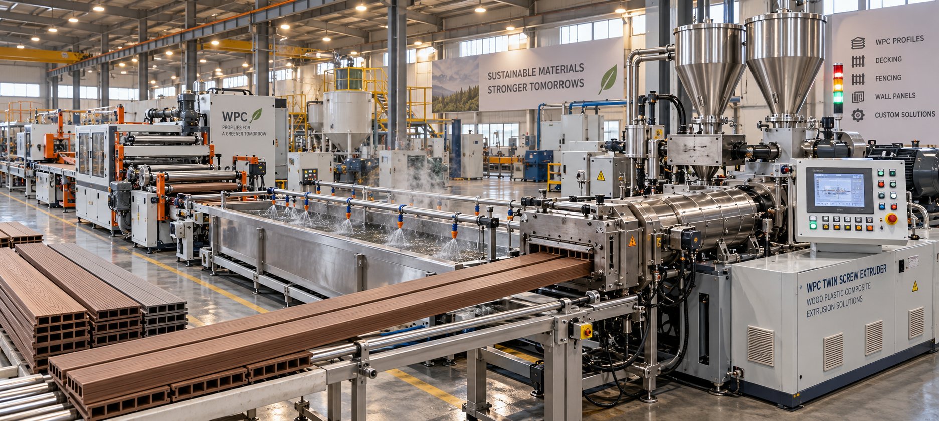
WPC Profile Extrusion Machine Decoded: Raw Blend To Flawless Profile
Oct 15, 2026
Learn how a WPC profile extrusion machine works — from extruder types and temperature zones to troubleshooting, wear management, and emerging co-extrusion trends.
Read Article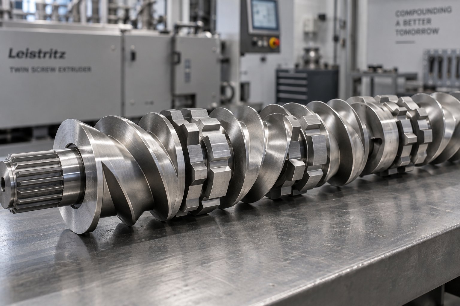
Twin Screw Extruder Screw Decoded: Geometry, Wear & Profile Fixes
Oct 14, 2026
Master twin screw extruder screw design: geometry parameters, kneading block stagger angles, element classification, wear mechanisms, and profile troubleshooting fixes.
Read Article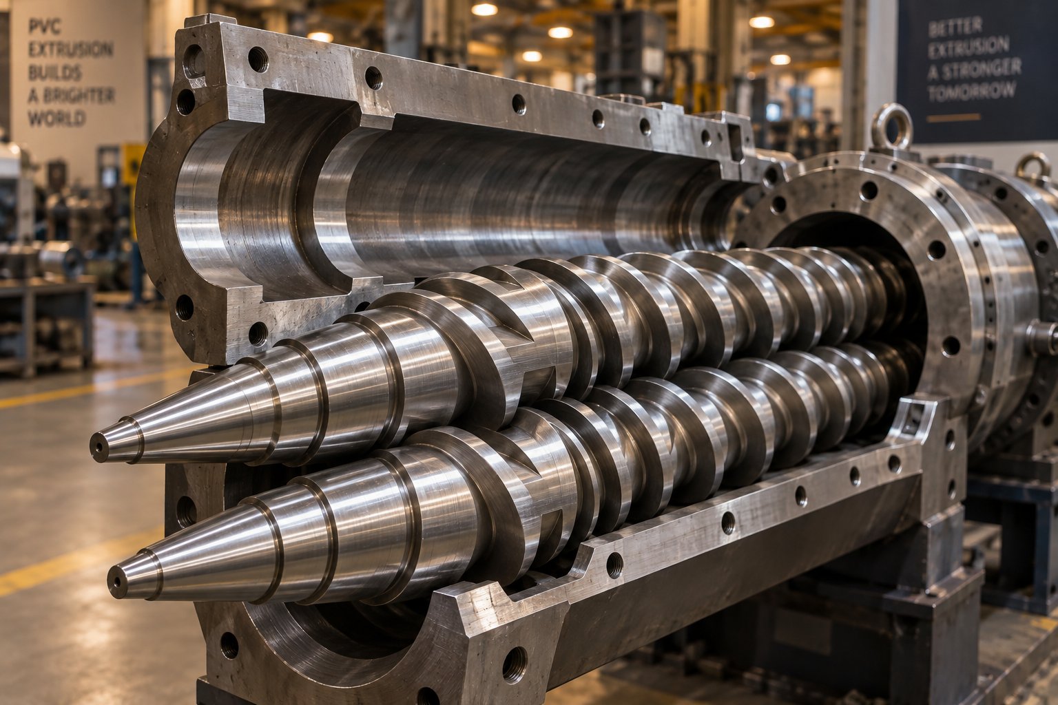
Your Extruder Screw Barrel For PVC Is Burning Resin — Here's Why
Oct 14, 2026
PVC burns resin when screw barrel geometry, metallurgy, or temperature zoning is wrong. Learn the exact specs, alloys, and wear fixes for PVC extrusion.
Read ArticleLooking for something else?
Search by material, symptom or product and jump straight to the relevant page.
These are navigation suggestions based on keyword matching — not a quotation, not a delivery commitment, and not a substitute for engineering review. Final specification is confirmed by our engineers against your drawings and processed material.
Need help with screw barrel selection?
Share your machine model, processed material and application. Our team can help with pricing and technical support.