


What Is Sheet Extrusion and Why It Matters
Imagine turning a handful of tiny plastic pellets into a perfectly smooth, precisely gauged sheet that could become anything from a yogurt-cup lid to a car dashboard panel. That transformation happens millions of times a day through one of the plastics industry's most reliable processes.
Sheet extrusion is a continuous manufacturing process in which thermoplastic resin is melted inside a screw-and-barrel extruder and forced through a flat die to produce solid plastic sheets of controlled width and thickness, typically 0.25 mm (0.010 in) and above.
The thickness threshold is an important distinction. Below roughly 0.25 mm, the product is generally classified as film and relies on different downstream equipment such as chill-roll casting or blown-film towers. Extruded sheet, by contrast, exits the die onto a polishing roll stack that simultaneously cools, calibrates, and finishes the surface, resulting in rigid or semi-rigid flat stock ready for further converting.
Defining Sheet Extrusion
At its core, plastic sheet extrusion is elegantly straightforward. Thermoplastic pellets enter a heated barrel, a rotating screw melts and conveys the material forward, and the resulting melt is pushed through a precision flat die. A set of chrome-plated chill rolls then solidifies the extrudate into a uniform sheet. Downstream equipment trims the edges, measures thickness in real time, and either winds the sheet into rolls or cuts it into flat blanks. The entire sequence runs continuously, enabling high throughput and consistent quality over long production campaigns.
Where Extruded Sheet Is Used
Few plastics processes touch as many end markets. You'll find extruded sheet across a remarkable range of applications:
- Packaging - thermoformed trays, clamshells, blister packs, and cup lids
- Automotive - interior trim panels, dashboards, and protective covers
- Construction - wall cladding, roofing panels, and decorative laminates
- Medical - sterile-barrier packaging, disposable trays, and device housings
- Signage and displays - point-of-purchase stands, glazing, and advertising panels
This versatility stems from the process's ability to handle a wide polymer range. Polypropylene (PP), polyethylene terephthalate (PET), polystyrene (PS), high-impact polystyrene (HIPS), acrylonitrile butadiene styrene (ABS), polycarbonate (PC), and polyvinyl chloride (PVC) are all routinely run on the same basic line platform with adjustments to screw design, temperature profiles, and roll-stack settings.
Why Sheet Extrusion Matters in Plastics Manufacturing
Cost efficiency is a major driver. Continuous operation means high output at low per-unit cost, and the flat-sheet format feeds directly into downstream converting operations like thermoforming, lamination, die cutting, and printing. In fact, packaging alone consumes roughly 30% of all extruded sheet output, while food and agriculture applications represent about 40% of the thermoformed plastics market. The result is a supply chain where a single sheet line can serve multiple converting steps and end products.
Equally important is dimensional control. Modern lines pair precise die-lip adjustment with inline thickness scanning and automated feedback, holding tight gauge tolerances that rigid-packaging and automotive customers demand. That level of repeatability, combined with material flexibility, is exactly why this process remains a cornerstone of flat-plastic production worldwide.
Of course, reliable output depends on much more than simply feeding pellets into a barrel. Every stage of the process, from screw geometry to chill-roll temperature, plays a direct role in determining the final sheet's thickness uniformity, surface finish, and mechanical properties.
How the Sheet Extrusion Process Works Step by Step
Picture a relay race where each runner must hit a precise pace, or the whole team loses. The sheet extrusion process works much the same way: raw resin passes through a carefully sequenced chain of stages, and the settings at every station directly shape the finished sheet's thickness, clarity, and surface quality. A misstep at any point, whether a temperature spike in the barrel or a misaligned die lip, ripples through to the final product.
Here is the complete sheet plastic extrusion sequence from hopper to finished stack:
- Resin feeding and metering
- Melting and conveying in the screw-and-barrel system
- Melt filtration through the screen pack and breaker plate
- Melt distribution in the flat die
- Cooling and calibration on the polishing/chill-roll stack
- Haul-off, thickness measurement, edge trimming, and winding or cutting-to-length
From Pellet to Melt
Sheet production begins at the hopper, where thermoplastic pellets or granules are gravity-fed, or vacuum-loaded from bulk storage, into the extruder's feed throat. Gravimetric dosing feeders meter the exact ratio of virgin resin, recycled regrind, color masterbatch, and any functional additives such as UV stabilizers or slip agents. Consistency here is non-negotiable: if the feed rate fluctuates, you'll see surging downstream that shows up as gauge bands in the finished sheet. The feed throat itself is water-cooled to prevent premature melting, which could cause pellets to stick together and bridge inside the hopper.
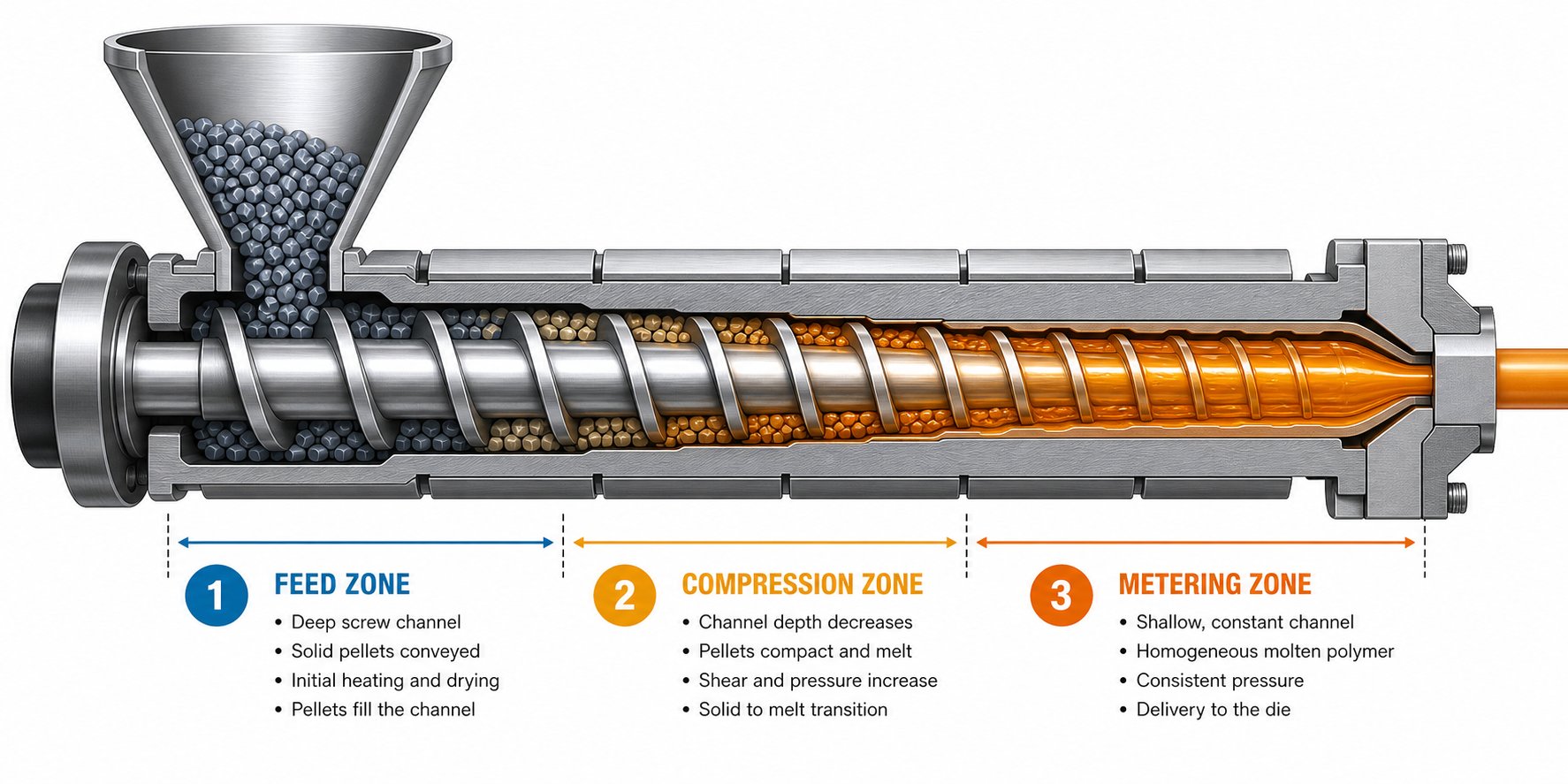
Once the pellets drop into the barrel, the rotating screw takes over. Think of the screw as three zones working in concert:
- Feed zone - The screw channel is deepest here, accepting solid pellets and conveying them forward. Barrel temperatures are relatively low, and frictional heat begins the softening process.
- Compression (transition) zone - Channel depth decreases progressively, squeezing the material. This compression, combined with rising barrel temperatures, forces air out and completes the melting. Compression ratios typically fall between 2.5:1 and 4.5:1, depending on the polymer.
- Metering zone - Channel depth is constant again, but shallower than the feed zone. The fully molten polymer is homogenized and pressurized for delivery to the die. Screw L/D ratios of 24:1 to 36:1 are standard for sheet lines, with longer ratios providing better melt uniformity.
Barrel temperatures are controlled across five to eight independent zones, each maintained within roughly ±1 °C. For polypropylene, zones might ramp from 180 °C at the feed end to 230 °C near the discharge. Polycarbonate, by contrast, demands temperatures up to 280-300 °C. Screw speed is the other critical lever: faster rotation increases output and shear heat but can degrade heat-sensitive polymers; slower speeds risk extended residence time and thermal degradation. Finding the sweet spot is material- and line-specific.
Before reaching the die, the melt passes through a screen pack supported by a breaker plate. The screen pack filters out solid contaminants, degraded particles, and foreign objects that would otherwise cause streaks or specks in the sheet. Equally important, the breaker plate eliminates the spiral flow memory imparted by the rotating screw, converting it into straight-line flow. This stage also builds back pressure, which improves mixing. Pressure transducers on either side of the screen pack let operators monitor filter condition: a rising pressure differential signals a clogged screen that needs changing before it affects gauge stability.
Die Forming and Sheet Calibration
The filtered, pressurized melt now enters the flat die, the component that transforms a circular melt stream into a wide, thin curtain. Two common die geometries handle this job. A coat-hanger die features a teardrop-shaped manifold that gradually narrows from center to edges, equalizing flow velocity and pressure drop across the full width. A T-slot die uses a constant cross-section manifold, which is simpler but can cause uneven flow, especially near the edges. For demanding sheet production, coat-hanger designs are the preferred choice.
The die lip, the final opening through which the melt exits, is adjustable via push-pull bolts or thermal expansion bolts spaced every 30-80 mm across the width. These adjustments let operators fine-tune the local thickness profile. On high-end lines, servo-driven die bolts receive continuous feedback from online thickness gauges and adjust automatically, holding tolerances as tight as ±1-2%. The die-lip gap is set slightly wider than the target sheet thickness to account for die swell and the draw-down that occurs as the haul-off pulls the sheet away.
Temperature uniformity across the die width is just as important as mechanical adjustment. Even a few degrees of variation between zones translate directly into thick and thin bands in the finished sheet.
Cooling, Gauging, and Downstream Finishing
As the melt curtain exits the die, it enters the polishing/chill-roll stack, typically a three-roll configuration arranged vertically or at an incline. Each roll plays a distinct role:
- Top (chill) roll - Chrome-plated and water-cooled, it initiates solidification of the sheet's upper surface.
- Middle (polishing) roll - Determines the primary surface finish: mirror-chrome for gloss, matte or textured for specialized applications.
- Bottom roll - Often rubber-covered, it provides grip to pull the sheet through without marking the top surface.
Roll temperatures are independently controlled, typically within ±1 °C. Lower roll temperatures yield higher gloss and suppress crystallinity in semi-crystalline polymers like PP, while higher temperatures reduce the sheet's tendency to block during stacking. For thicker gauge or tighter tolerance demands, five-roll stacks add extra cooling and calibration stages.
Downstream of the roll stack, pneumatic or mechanically loaded haul-off rollers pull the cooled sheet at a speed precisely synchronized with extruder output. This speed ratio is the primary lever for final gauge control: pull too fast and the sheet stretches thin; pull too slowly and it thickens and can develop waviness.
An inline thickness gauge, commonly beta-ray, laser, or infrared, scans continuously across the sheet width, feeding real-time data back to the die-adjustment system for automatic correction. Surface inspection cameras may also check for gels, black specks, and scratches. After gauging, edge trimmers remove the ragged margins, typically 20-40 mm per side, and the trim scrap is immediately granulated and recycled back into the feed stream. Finally, rigid sheet is cut to programmed lengths by a shear cutter or flying knife and dropped onto automatic stackers, while thinner, more flexible gauges wind onto cores for roll-form delivery to thermoforming operations.
Every parameter discussed here, from barrel temperature profiles and screw speed to die-lip gap, chill-roll temperature, and line speed, interacts as part of a tightly coupled system. Changing one variable invariably affects others. That interdependence is exactly why understanding each piece of equipment in detail, from screw geometry to roll-stack metallurgy, separates a well-optimized line from one battling chronic scrap.
Essential Extrusion Line Components and Equipment
A sheet extrusion line is only as strong as its weakest station. Swap a precision die onto an undersized extruder, or pair a high-output barrel with a poorly designed roll stack, and the result is the same: off-spec sheet and avoidable downtime. Understanding what each piece of sheet extrusion machinery contributes, and how the components interact, is the foundation for building a line that actually delivers consistent gauge, surface quality, and throughput day after day.
Extruder and Screw Design Essentials
The sheet extruder is the heart of the line, responsible for converting solid pellets into a homogeneous, pressurized melt. Two broad architectures dominate: single-screw and twin-screw. For most sheet applications running pre-compounded pellets of PP, PET, PS, ABS, or PC, the single-screw extruder remains the workhorse choice due to its lower complexity, lower cost, and proven reliability in continuous flat-die operation. Twin-screw machines earn their place when the process demands intensive mixing, powder feeding (rigid PVC dry blends, for instance), or high filler loading that a single screw simply cannot homogenize.
The comparison below highlights where each architecture fits best:
| Criterion | Single-Screw Extruder | Twin-Screw Extruder |
|---|---|---|
| Typical Sheet Applications | PP, PET, PS, HIPS, ABS, PC, PETG sheet from compounded pellets | Rigid PVC dry blend, highly filled or foamed sheet, WPC board |
| Best Feed Form | Pellets and granules | Powders, dry blends, variable-density regrind |
| Relative Capital Cost | Lower | Higher |
| Throughput Range | Moderate to high (up to 2,000+ kg/hr on large screws) | Moderate to high; output depends on screw diameter and design |
| Mixing Capability | Low to moderate; improved with barrier or mixing-section screws | Moderate to high; intermeshing elements create strong dispersive mixing |
| Maintenance Complexity | Simpler: fewer wear parts, easier cleaning, faster training | More demanding: more wear components, longer changeover, higher spare-parts inventory |
| Pressure Stability at the Die | Excellent for steady pellet-fed extrusion | Good, but more process variables to control |
Within a single-screw sheet extruder, screw design is the single most important variable after polymer selection. Key design parameters include:
- L/D ratio - Most sheet lines use screws between 24:1 and 36:1. Longer L/D ratios provide more barrel residence for thorough melting and mixing, which benefits crystalline polymers like PET and PP.
- Compression ratio - The ratio of feed-zone channel depth to metering-zone depth. Polyolefins typically process well at 3:1 to 4:1, while shear-sensitive PVC requires a gentler 1.8:1 to 2.5:1 to avoid thermal degradation.
- Barrier flight designs - A secondary flight in the transition zone separates the solid bed from the melt pool, reducing unmelts and improving temperature uniformity across the melt stream.
- Metering-zone geometry - Channel depth and length in this zone govern output rate and melt-pressure stability. A well-designed metering section minimizes pressure pulsation, which directly translates into tighter gauge tolerance on the finished sheet.
Barrel construction matters just as much. High-quality barrels are nitrided or bimetallic-lined to resist wear from abrasive fillers and glass-reinforced resins. Heating is managed through multiple independent zones, each with electric band heaters and forced-air or water cooling jackets, allowing precise ramp-up profiles tailored to the polymer. For plants running diverse polymers across sheet, film, pipe, or recycling lines, sourcing purpose-built components from a specialist supplier simplifies maintenance planning. NANHAIYA's single screw barrel solutions, for example, are engineered specifically for this range of applications, offering application-matched screw and barrel configurations that support reliable melt quality across multiple polymer families.
Die Geometry and Melt Distribution
The flat die converts a cylindrical melt stream into a thin, wide curtain. Two primary designs dominate sheet extrusion lines, and the difference matters more than many operators realize:
- Coat-hanger die - Features a teardrop or parabolic backline manifold that tapers from center to edges. This geometry equalizes flow velocity across widths that can exceed 3,500 mm, delivering superior cross-directional uniformity. It is the preferred choice for tight-tolerance sheet production.
- T-slot die - Uses a constant cross-section manifold. Simpler and less expensive, but more prone to edge-starving on wide sheets. Best suited for narrower widths or less demanding gauge requirements.
Both designs incorporate fine-tuning hardware that allows operators, or automated systems, to dial in the thickness profile across the full sheet width:
- Flex-lip adjustments - Push-pull bolts (or thermally actuated bolts on automatic lines) spaced every 30-80 mm across the die lip to increase or decrease the local gap.
- Choker bars - Internal flow restrictors that can throttle material flow in specific zones upstream of the lip, compensating for viscosity differences or flow imbalances.
- Restrictor bars - Fixed or adjustable bars that further shape the pre-land flow distribution, especially useful when switching between polymers with significantly different melt viscosities.
Temperature uniformity across the die body is critical. Even a 3-5 °C variation between zones can produce visible thick-and-thin bands, so modern dies use individually controlled cartridge heaters and external insulation blankets to keep the melt flowing at a consistent viscosity from edge to edge.
Chill Rolls, Haul-Off, and Downstream Systems
The moment the melt curtain exits the die lip, the cooling stack takes control of final sheet quality. Two configurations are common on modern sheet extrusion lines:
| Configuration | Roll Arrangement | Typical Use Case |
|---|---|---|
| Vertical (Down-Stack) | Three rolls stacked vertically; melt enters at the top nip | Most common for thin-to-medium gauge sheet (0.25-6 mm); compact footprint |
| Horizontal (Inline) | Rolls arranged horizontally; melt enters at the first nip | Heavy-gauge sheet and board; easier operator access for thicker products |
| Two-Roll vs. Three-Roll | Two-roll stacks omit the third calibrating roll | Two-roll setups suit simpler or thinner-gauge products; three-roll provides better thickness control and dual-side polishing |
In a standard three-roll vertical stack, the top and middle rolls form the primary nip where the melt is first compressed to target gauge. The middle roll determines the primary surface finish, whether mirror-gloss chrome, matte, or embossed texture. Roll temperatures are independently controlled, often within ±0.5 °C, because even small deviations affect crystallization, gloss, and the sheet's tendency to curl during downstream converting.
Beyond the chill-roll stack, several downstream systems work in concert to finish the sheet:
- Haul-off unit - Motorized rubber-covered or steel nip rollers pull the sheet at a precisely controlled speed. The speed ratio between haul-off and extruder output is the primary tool for setting final sheet thickness. Pull faster to draw the sheet thinner; slow down to allow a heavier gauge.
- Beta-gauge or infrared thickness scanners - Mounted on a traversing frame, these sensors sweep continuously across the sheet width, feeding real-time thickness data back to automated die-bolt controllers. This closed-loop system keeps gauge variation within the ±3% target that thermoforming and packaging customers demand.
- Edge trimmers - Rotary knife or razor assemblies shave 20-40 mm from each side to remove the thickened bead edge. The trim scrap is granulated inline and returned to the extruder feed, keeping waste to a minimum.
- Winders and sheet stackers - Thinner, flexible gauge sheet (common in thermoforming) is wound onto cardboard or steel cores. Thicker, stiffer sheet is cut to length by a flying shear and automatically stacked on pallets for shipment.
Each of these downstream components must be speed-synchronized with the extruder and roll stack. A mismatch of even a fraction of a percent between haul-off speed and line speed can introduce machine-direction gauge bands or sheet necking. Modern sheet extrusion lines tie all drives to a single line-control PLC, enabling one-touch speed adjustments that cascade proportionally through every station.
With a clear picture of the hardware, the next logical question is which polymer you actually feed through it, because material choice dictates almost every parameter setting discussed above.
Polymer Selection Guide for Every Sheet Application
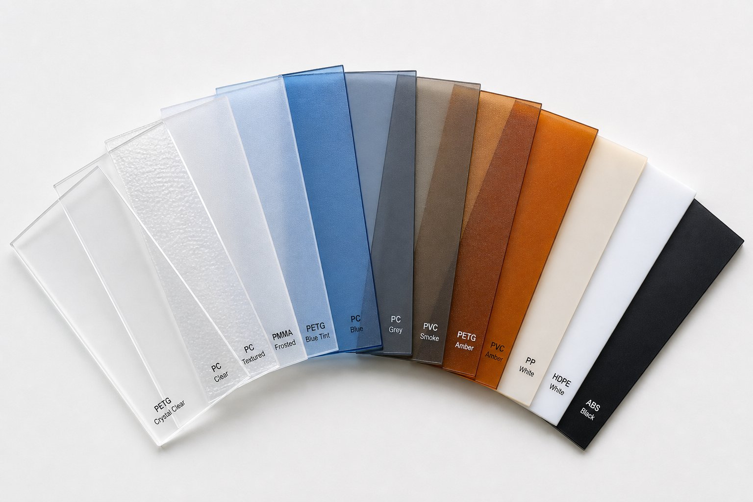
Every screw speed, barrel temperature, and chill-roll setting discussed so far hinges on one upstream decision: which polymer goes into the hopper. Choosing the wrong resin for the job doesn't just compromise sheet performance; it forces the entire line to fight against the material's natural processing behavior. A solid grasp of polymer sheet extrusion fundamentals, from melt rheology to crystallization tendencies, turns material selection from guesswork into a strategic advantage.
Commodity Polymers for Sheet Extrusion
Commodity resins dominate the sheet market because they deliver dependable performance at competitive cost. Here is where each one excels:
- Polypropylene (PP) - Lightweight, chemical-resistant, and fatigue-tolerant, PP is a staple in food packaging, stationery, and reusable containers. It thermoforms well and offers excellent hinge performance for living-hinge designs. PP sheet extrusion typically runs at melt temperatures of 232-249 °C, with nucleating agents often added to boost clarity and speed crystallization on the chill rolls. Typical sheet thickness ranges from 0.3 mm to 3 mm for packaging and up to 10 mm for industrial applications.
- Polyethylene (PE / HDPE) - Valued for outstanding chemical resistance and low moisture absorption, PE sheet serves chemical-tank liners, playground equipment, and marine-board applications. Processing temperatures fall around 200-235 °C. Because PE is semi-crystalline and relatively soft, precise chill-roll temperature control is essential to manage crystallinity and maintain flatness. Common gauges span 1 mm to 12 mm.
- Polyethylene Terephthalate (PET) - The go-to resin for thermoformed clamshells, blister packs, and food trays. PET sheet extrusion delivers outstanding optical clarity, good barrier properties, and broad recyclability. It is a hygroscopic polymer, so thorough drying to below 50 ppm moisture is critical before processing to prevent hydrolytic degradation and haze. Melt temperatures typically range from 260 to 280 °C, and rapid quenching on the chill rolls keeps the sheet amorphous and crystal-clear. Sheet thicknesses for packaging usually fall between 0.2 mm and 2 mm.
- Polystyrene (PS) and High-Impact Polystyrene (HIPS) - PS offers rigidity and excellent clarity at low cost, making it ideal for disposable cups and lids. HIPS adds rubber modification for improved impact strength, which suits dairy cups, disposable trays, and food-service containers. Both process easily at 200-240 °C and thermoform at relatively low temperatures. HIPS is one of the easiest materials to thermoform, though it tends to be more brittle than ABS. Typical gauges run from 0.25 mm to 6 mm.
- Polyvinyl Chloride (PVC) - Rigid PVC sheet is widely used for credit cards, blister-pack backing, chemical equipment panels, and construction cladding. It is shear-sensitive, so processing demands lower compression-ratio screws (1.8:1 to 2.5:1) and tightly controlled melt temperatures, generally between 170 and 200 °C. PVC is often processed on twin-screw extruders from dry-blend powder rather than pellets. Sheet thickness ranges from 0.15 mm for thin blister stock up to 25 mm for industrial panels.
Engineering Polymers and Specialty Resins
When applications demand higher heat resistance, greater toughness, or optical properties beyond what commodity resins deliver, engineering polymers step in:
- Acrylonitrile Butadiene Styrene (ABS) - ABS combines rigidity, impact strength, and a high-quality surface finish, making it a favorite for luggage shells, automotive interior trim, appliance housings, and recreational vehicle panels. It processes at 220-260 °C and must be dried before extrusion because it is moderately hygroscopic. Sheet gauges typically range from 0.5 mm to 12 mm.
- Polycarbonate (PC) - Renowned for exceptional impact resistance, optical clarity approaching 88-92% light transmission, and heat resistance up to a glass transition temperature of roughly 147 °C, PC sheet is the material of choice for machine guards, safety glazing, greenhouse panels, and electronic display covers. Processing demands high melt temperatures (280-320 °C) and rigorous drying. It is vulnerable to solvents and oils, a factor that must be considered in end-use environments. Typical thickness spans 0.5 mm to 15 mm.
- PETG (Glycol-Modified PET) - Think of PETG as PET's more forgiving cousin. The glycol modification lowers crystallinity, which improves toughness, makes the material easier to thermoform, and eliminates the need for pre-drying in many cases. PETG is widely used in point-of-purchase displays, medical packaging, and face shields, offering clarity up to roughly 90% in oriented form. It processes at slightly lower temperatures than standard PET and provides excellent chemical resistance. Common sheet thicknesses range from 0.5 mm to 6 mm.
How to Match Polymer to Application
Selecting the right resin is rarely about a single property. You're balancing a matrix of requirements: Does the end product need optical clarity or just opacity? Will it face chemical exposure, UV weathering, or high-temperature sterilization? Is thermoformability essential, or will the sheet be used as flat stock? And what does the project budget allow?
The table below maps the key selection criteria across all eight polymer families to help you narrow the field quickly:
| Polymer | Clarity | Impact Strength | Max Service Temp | Thermoformability | Recyclability | Relative Cost |
|---|---|---|---|---|---|---|
| PP | Moderate (good with nucleating agents) | Moderate | ~100-130 °C | Very Good | Excellent (resin code 5) | Low |
| PE (HDPE) | Translucent | Good | ~80-120 °C | Good | Excellent (resin code 2) | Low |
| PET | Excellent | Moderate | ~70 °C (amorphous) | Excellent | Excellent (resin code 1) | Low-Moderate |
| PS / HIPS | High (PS); Moderate (HIPS) | Low (PS); Moderate (HIPS) | ~70-90 °C | Excellent | Limited (resin code 6) | Low |
| PVC | Moderate to Good | Moderate | ~60-80 °C | Good | Limited (resin code 3) | Low |
| ABS | Opaque | Very Good | ~85-100 °C | Very Good | Limited (resin code 7) | Moderate |
| PC | Excellent | Outstanding | ~115-135 °C | Good (needs high forming temps) | Recyclable but limited streams | High |
| PETG | Very Good | Very Good | ~60-70 °C | Excellent | Limited (often confused with PET in sorting) | Moderate |
A few practical rules of thumb simplify the decision. If you need the clearest possible thermoformed food tray at the lowest cost, PET wins. If impact resistance matters more than heat tolerance, PETG or ABS should top the list. For outdoor glazing or safety shields, PC is difficult to beat despite its higher price. And when chemical exposure or sterilization is part of the equation, PP and HDPE earn their keep with inert, FDA-friendly surfaces.
Material choice, however, is only half the preparation story. Even the ideal polymer will produce defective sheet if it reaches the extruder carrying excess moisture or lacking the right additive package, a reality that makes upstream material preparation every bit as important as the resin itself.
Material Preparation: From Drying to Additives for a Plastic Sheet Extruder
A perfectly designed screw, a flawlessly tuned die, and a state-of-the-art roll stack will still produce reject-grade sheet if the resin entering the feed throat carries too much moisture or the wrong additive balance. Material preparation is the invisible gatekeeper of sheet quality, yet it remains one of the most overlooked steps on the production floor. Getting it right means understanding why certain polymers demand drying, how functional additives shape both processing and performance, and where regrind fits into a sustainable production strategy.
Resin Drying Requirements for Hygroscopic Materials
Not every polymer needs drying, but the ones that do will punish you for skipping it. Hygroscopic resins, polymers that actively absorb moisture from ambient air, undergo a chemical reaction called hydrolysis when processed wet. At the high temperatures inside an extruder barrel, trapped water molecules don't simply evaporate. They break polymer chains apart, reducing molecular weight (measured as intrinsic viscosity, or IV, in PET) and triggering a cascade of visible defects:
- Splay (silver streaks) - Boiling moisture expands rapidly at the die exit, leaving silvery, fan-shaped marks on the sheet surface.
- Bubbles and voids - Steam pockets trapped inside the melt create internal voids that weaken the sheet and ruin optical clarity.
- Haze and cloudiness - Microbubbles scatter light, turning what should be crystal-clear PET or PC sheet into a hazy, off-spec product.
- Yellowing and color shift - Hydrolytic degradation changes the resin's base color, making consistent color matching nearly impossible even with a perfect masterbatch.
- Reduced mechanical strength - Shorter polymer chains mean lower impact resistance, reduced elongation, and brittle sheet that cracks during thermoforming.
Imagine running a PET sheet extruder loaded with undried resin. The finished sheet looks foggy, snaps during thermoforming trials, and fails the customer's clarity specification. The entire run becomes scrap, and the root cause traces back to a dryer that wasn't given enough time or temperature to do its job.
The solution is a desiccant dryer paired with an insulated drying hopper mounted directly above the extruder feed throat. Unlike simple hot-air dryers, desiccant systems circulate air through a molecular-sieve bed that strips moisture down to a dew point of -40 °C or lower. This ultra-dry air then flows through the resin bed in the hopper, pulling absorbed water out of each pellet's interior over several hours. A properly sized system maintains the resin at the correct temperature for the required residence time, ensuring every pellet reaches the target moisture level before it drops into the screw.
Here are the recommended drying parameters for the most common hygroscopic sheet resins:
- PET - Dry at 160-165 °C (325 °F) for 4-6 hours; target moisture below 50 ppm (0.005%)
- Polycarbonate (PC) - Dry at 120 °C (250 °F) for 2-4 hours; target moisture below 200 ppm (0.02%)
- ABS - Dry at 80 °C (180 °F) for 2-3 hours; target moisture below 500 ppm (0.05%)
- Nylon (PA6, PA66) - Dry at 80-95 °C (180-200 °F) for 3-6 hours; target moisture below 1,000 ppm (0.1%)
- PBT - Dry at 120 °C (250 °F) for 3-4 hours; target moisture below 200 ppm (0.02%)
Non-hygroscopic polymers such as PP, PE, and PS do not absorb moisture into their pellet structure, so they typically don't require desiccant drying. However, surface moisture from condensation can still cause cosmetic defects, so a brief pass through a warm-air hopper dryer before processing is good insurance, especially in humid climates.
Functional Additives and Their Processing Effects
Raw resin alone rarely meets every performance requirement straight out of the bag. Additives tailor the sheet's properties, appearance, and processability to the specific end use. The challenge? Every additive you introduce changes the melt's behavior inside the extruder, so understanding the trade-offs is essential for stable production.
Here are the most common additive families used in sheet extrusion and how they affect processing:
- Colorants and masterbatch - A sheet extrusion plastic colorant, whether delivered as liquid color, solid masterbatch, or pre-compounded concentrate, must disperse uniformly throughout the melt. Poor dispersion leads to streaks, swirls, or color-intensity variation across the sheet width. Pigment particle size and carrier-resin compatibility are key; always match the masterbatch carrier to the base polymer to avoid delamination or haze. High pigment loadings can increase melt viscosity slightly, which may require minor adjustments to barrel temperatures or screw speed.
- UV stabilizers - Essential for any sheet destined for outdoor exposure, such as construction cladding, greenhouse panels, or signage. Hindered-amine light stabilizers (HALS) and UV absorbers (benzotriazoles, triazines) protect the polymer from photo-degradation. These additives are heat-stable at normal processing temperatures and have minimal effect on melt flow, making them straightforward to incorporate.
- Nucleating agents - Widely used in PP sheet extrusion to accelerate crystallization on the chill rolls. Faster crystallization yields smaller, more uniform spherulites, which translates into improved clarity, higher stiffness, and shorter cycle times during downstream thermoforming. The downside is that excessive nucleation can increase brittleness, so loading levels must be balanced carefully.
- Anti-static agents - Reduce surface resistivity so sheets don't cling together during stacking or attract dust during storage. Internal anti-static agents migrate to the surface over time, which means they can slightly affect surface energy and printability.
- Slip agents - Fatty-acid amides (such as erucamide or oleamide) reduce the coefficient of friction between stacked sheets, preventing blocking. Like anti-static agents, they bloom to the surface, and excessive loading can interfere with downstream printing, lamination, or heat sealing.
- Impact modifiers - Rubber or elastomer-based additives blended into brittle resins like PS or PET to improve drop-impact and puncture resistance. Higher impact-modifier loading increases melt viscosity and can reduce sheet stiffness and clarity, so the formulation is always a compromise between toughness and other properties.
The overarching rule is straightforward: every additive shifts the melt's rheological fingerprint. Increasing total additive loading raises or lowers viscosity depending on the additive type, alters die swell, and can change the sheet's cooling behavior on the roll stack. Run a small-scale trial whenever you introduce a new additive or change loading levels, and verify that barrel temperatures, screw speed, and die-lip settings still produce on-spec sheet before committing to a full production run.
Regrind, Recycled Content, and Sustainability
Sheet extrusion generates edge trim on every meter of product that rolls off the line. Those trimmed strips, plus any start-up purge or off-spec sheet, represent valuable post-industrial regrind (PIR) that can be granulated and fed directly back into the extruder alongside virgin pellets. Regrind reuse is both an economic win, cutting raw material costs, and an environmental one, keeping usable polymer out of landfills.
However, regrind is not a free lunch. Each time a polymer passes through the melt process, it accumulates heat history. Molecular chains shorten, melt viscosity shifts, and properties like impact strength, elongation, and color consistency gradually degrade. Practical limits on regrind content depend on the polymer and the end-use requirements:
- PP and PE - Tolerant of regrind; many processors run 20-30% regrind with minimal property loss. Some non-critical applications accept even higher percentages.
- PET - More sensitive due to IV loss during reprocessing. Food-grade PET sheet lines often cap regrind at 10-15%, and the regrind itself may need re-drying to prevent further hydrolytic degradation.
- PS / HIPS - Generally handles 15-25% regrind well, though impact strength in HIPS decreases as the rubber phase degrades with repeated heat exposure.
- ABS - Regrind levels of 15-20% are common, but yellowing and reduced gloss can appear at higher loadings.
- PC - Particularly sensitive to reprocessing. Regrind above 10-15% may cause noticeable yellowing and reduced impact performance.
Beyond in-house regrind, the broader industry is moving rapidly toward incorporating post-consumer recycled (PCR) content and bio-based resins. Mono-material sheet structures, where every layer is the same polymer family, are gaining traction because they simplify recycling streams. A PET tray made from a single polymer, for example, is far easier to sort and reprocess than a multi-layer structure combining PET with PE or EVOH barrier layers. Brand owners and retailers are increasingly specifying minimum recycled content, pushing sheet extruders to qualify PCR grades that meet both regulatory and aesthetic standards.
Bio-based resins such as PLA (polylactic acid) offer another sustainability pathway, though they bring their own processing quirks, including lower heat resistance and different crystallization behavior. The circular-economy trajectory is clear: material preparation increasingly means not just drying and dosing, but designing the entire formulation, virgin resin, regrind ratios, additive packages, and recycled content, to meet both performance specifications and end-of-life recyclability goals.
Even with perfectly prepared material, defects can still appear on the finished sheet. Knowing how to identify them quickly, trace them to their root cause, and apply the right corrective action is what separates a reactive operation from a truly optimized one.
Troubleshooting Common Sheet Extrusion Defects
A well-prepared resin, a properly designed screw, and a precisely adjusted die can still produce sheet that fails inspection. Defects have a stubborn way of appearing when multiple process variables drift simultaneously, and the real challenge is rarely spotting the flaw. It's tracing that flaw back to its origin. Whether you're operating a single sheet extruder machine or managing a fleet of sheet extruders across multiple lines, a structured diagnostic approach beats guesswork every time.
Identifying the Most Common Sheet Defects
Most sheet extrusion defects fall into a surprisingly short list of categories. Each one carries a visual fingerprint that, once you learn to read it, points directly toward the root cause. Here is what to watch for:
- Die lines - Continuous streaks running in the machine direction, visible as fine grooves or raised ridges on the sheet surface.
- Gauge variation (uneven thickness) - Thick-and-thin bands across the sheet width or along its length, detectable by touch or, more reliably, by inline scanning.
- Melt fracture - A rough, spiraling, or sharkskin-like texture caused by excessive shear stress as the melt exits the die lip.
- Surface roughness or orange peel - A matte, bumpy texture resembling the skin of an orange, often most visible under angled light.
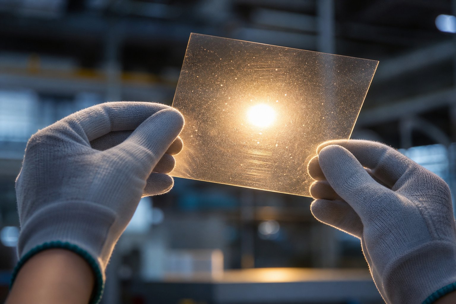
- Gels and unmelts - Small translucent or opaque specks embedded in the sheet, sometimes visible only when the sheet is held up to backlight.
- Moisture defects (splay and bubbles) - Silvery, fan-shaped streaks (splay) or trapped voids caused by water vapor flashing at the die exit.
- Warping and curl - Sheet that bows, twists, or curls after cooling, making it difficult to stack, cut, or thermoform.
- Plate-out and roll buildup - A waxy or sticky residue accumulating on chill rolls, haul-off rollers, or die lips, transferring back onto the sheet surface and causing haze or marks.
Each defect can originate from the material, the equipment, the process settings, or a combination of all three. The key is resisting the urge to tweak one parameter in isolation. A systematic root-cause approach that examines material condition, screw and barrel wear, die cleanliness, and temperature profiles together will resolve issues faster and prevent them from recurring.
Defect-Cause-Remedy Reference Table
The table below maps each major defect to its most likely root causes and the corresponding corrective actions. Bookmark it, print it, or post it next to your plastic sheet extruder machine's control panel. It will save hours of trial-and-error troubleshooting.
| Defect | Root Cause(s) | Corrective Action(s) |
|---|---|---|
| Die lines | Contamination or carbon buildup on die lip; damaged or scratched die-lip land; worn restrictor bar | Clean and polish die lip with brass tools; inspect and re-lap or replace damaged lip surfaces; replace worn restrictor bar; check screen pack for bypass that allows degraded material through |
| Gauge variation / uneven thickness | Poor die-lip bolt adjustment; inconsistent melt temperature across die zones; worn screw flights reducing pressure stability; haul-off speed fluctuation | Re-profile die-lip bolts using inline gauge data; verify all die-zone heaters and thermocouples; measure screw flight depth and replace if wear exceeds 10-15%; check haul-off drive for speed hunting |
| Melt fracture | Excessive shear stress at die exit; melt temperature too low for the resin's critical shear rate; die-lip land too long | Raise die-zone temperature to reduce melt viscosity; reduce extrusion rate (lower screw speed); widen die-lip gap slightly; consider a shorter land length or apply a fluoropolymer processing aid |
| Surface roughness / orange peel | Melt temperature too low for complete polymer flow-out; inadequate chill-roll contact pressure; unbalanced cooling from external air drafts | Increase barrel and die temperatures to improve melt flow; increase nip pressure at the chill-roll stack; enclose the cooling section to eliminate cross-drafts; verify roll surface condition (pitting or corrosion reduces contact quality) |
| Gels and unmelts | Insufficient melting or mixing in the screw; contaminated regrind containing crosslinked or degraded particles; wrong screen-pack mesh size | Switch to a barrier-flight or mixing-section screw design for better melt homogeneity; filter regrind more carefully and limit contaminated lots; use a finer screen pack (e.g., move from 40-mesh to 80-mesh or finer) |
| Moisture defects (splay, bubbles) | Inadequate resin drying; desiccant dryer malfunction (saturated beds, failed heaters); excessive ambient humidity during hopper loading | Verify dryer dew point is at or below -40 °C; confirm drying time and temperature meet resin manufacturer specs; install sealed hopper loaders to prevent re-absorption; run a moisture-analysis check on pellets at the feed throat |
| Warping and curl | Uneven cooling between the top and bottom sheet surfaces; residual orientation stress from excessive draw-down; asymmetric crystallization in semi-crystalline polymers | Balance chill-roll temperatures on both sides of the sheet; reduce the speed differential between die exit and haul-off; for PP and PET, adjust roll temperatures to equalize crystallinity through the sheet cross-section |
| Plate-out and roll buildup | Additive migration (slip agents, anti-stats, waxes) to roll surfaces; degraded polymer residue accumulating at die lip or on polishing rolls | Review additive loading levels and reduce if excessive; increase chill-roll temperature slightly to prevent condensation of volatiles; schedule regular roll cleaning intervals; consider switching to lower-migration additive grades |
A quick note on using this table effectively: most defects have more than one possible cause. Start with the most likely explanation, the one that aligns with what changed most recently on the line, whether it was a new resin lot, a temperature setpoint adjustment, or a screen-pack change. Fix one variable at a time and verify results before moving to the next.
Inline Quality Monitoring and Prevention
Reactive troubleshooting will always be necessary, but the most efficient sheet extruders pair diagnostic skill with real-time monitoring tools that catch deviations before they become scrap. Two inline technologies deserve a place on every modern line:
- Thickness scanning gauges - Beta-transmission, x-ray, or infrared sensors mounted on a traversing scanner frame sweep continuously across the moving sheet, mapping the thickness profile from edge to edge. The data feeds directly into an automatic die-bolt control system that adjusts individual lip bolts in real time, correcting gauge drift before the sheet reaches the winder. X-ray transmission gauges are gaining favor over traditional beta sources because they offer stronger signals, are unaffected by web flutter, and avoid the regulatory burden of radioactive isotopes.
- Surface inspection cameras - High-resolution line-scan cameras positioned after the chill-roll stack detect gels, black specks, scratches, and other surface anomalies at full line speed. Advanced systems classify defects by type and size, log their position on the roll, and trigger alarms when defect density exceeds a set threshold, giving operators immediate feedback on upstream process shifts.
Together, these systems create a closed-loop quality environment. Gauge data keeps thickness within specification, surface cameras flag cosmetic issues, and the combination provides a time-stamped quality record for every meter of sheet produced. That data trail proves invaluable during customer audits, root-cause investigations, and continuous-improvement programs.
The practical payoff is significant: plants that invest in inline monitoring consistently report lower scrap rates, fewer customer complaints, and faster changeover times because operators can see the effect of every adjustment in real time rather than waiting for offline lab results. Prevention, in short, always costs less than correction.
Knowing how to diagnose and fix problems within the process is powerful, but it also raises a broader question: how does sheet extrusion stack up against other plastic forming methods, and when is it truly the best manufacturing path?
Sheet Extrusion vs. Alternative Forming Processes
Every plastic part starts with a process decision, and getting it wrong means fighting defects and cost overruns from day one. A flat tray, a soda bottle, and a precision gear all begin as polymer pellets, yet each demands a fundamentally different forming method. So when does an extrusion sheet line earn its place over injection molding, blow molding, or another technique? The answer comes down to geometry, volume, thickness, and economics.
When Sheet Extrusion Outperforms Other Methods
Sheet extrusion thrives in a specific sweet spot: large, flat, or gently curved parts produced in continuous runs at moderate to high volumes. If your end product is a thermoforming blank, a rigid panel, a packaging tray, or a construction liner, a well-configured sheet line delivers unmatched throughput per dollar. The process runs continuously rather than in discrete cycles, so material flows non-stop from pellet hopper to finished stack, keeping per-unit costs low and changeover waste minimal compared to batch processes.
It also handles an exceptionally broad thickness window, from roughly 0.25 mm up to 25 mm or more, across commodity and engineering polymers alike. That flexibility means a single sheetline can supply thermoformed clamshells one week and heavy-gauge industrial panels the next with only a die-lip and roll-stack adjustment.
However, the process has clear boundaries. Complex three-dimensional geometry with ribs, bosses, or internal cavities falls outside its capability. Hollow parts are off the table entirely. And when the target gauge drops below 0.25 mm, cast film extrusion or blown film takes over with better gauge control and higher speeds at ultra-thin dimensions.
Process Comparison Matrix
The table below sets sheet extrusion side by side with five alternative forming processes across the criteria that matter most when choosing a manufacturing path. Use it as a quick-reference decision tool.
| Criterion | Sheet Extrusion | Injection Molding | Cast Film Extrusion | Calendering | Compression Molding | Blow Molding |
|---|---|---|---|---|---|---|
| Process Principle | Melt forced through a flat die, cooled on a roll stack into rigid/semi-rigid sheet | Melt injected into a closed mold cavity, cooled, and ejected as a discrete 3D part | Melt extruded through a flat die onto a single chill roll to produce thin, flexible film | Melt passed through a series of heated counter-rotating rolls to form sheet or film | A pre-weighed charge is placed into a heated mold and pressed under hydraulic force to cure or solidify | A parison or preform is inflated with air inside a mold to form a hollow part |
| Part Geometry | Flat or gently curved; feeds thermoforming for 3D shapes | Complex 3D with ribs, bosses, undercuts, snap fits | Flat, thin, flexible web | Flat sheet or film; limited profile variation | Thick, structural, relatively simple 3D | Hollow thin-walled shapes (bottles, tanks, ducts) |
| Thickness Range | 0.25 mm to 25+ mm | 0.5 mm to ~10 mm wall thickness | Below 0.25 mm (film gauge) | 0.1 mm to ~2 mm | 1 mm to 25+ mm | 0.2 mm to ~6 mm wall thickness |
| Production Volume Economics | Moderate to high; continuous process keeps unit cost low | High volume for best ROI due to expensive tooling | High volume; very fast line speeds | High volume; capital-intensive lines | Low to medium; longer cure cycles raise unit cost | Medium to high |
| Tooling Cost | Low to moderate (flat die + roll stack) | High (steel mold with cooling channels) | Low to moderate (flat die) | High (precision multi-roll calender) | Medium (matched metal molds) | Medium (blow mold + parison die) |
| Material Waste | Low; edge trim is granulated and recycled inline | Low to moderate (runners, sprues recyclable) | Very low; minimal edge trim | Low; continuous process | Moderate (flash and trim from charge overflow) | Moderate (flash, tails, and dome scrap) |
| Surface Finish | Excellent; mirror-gloss, matte, or textured via roll surface | Excellent; replicates mold texture precisely | Good to excellent on chill-roll side | Good; controlled by roll surface quality | Moderate; limited by mold texture and flow | Moderate; some parting-line marks |
| Cycle Time | Continuous (output measured in kg/hr or m/min) | Fast discrete cycles (seconds per shot) | Continuous; higher line speeds than sheet | Continuous | Slow (minutes per part due to curing) | Fast (seconds per part) |
Choosing the Right Manufacturing Path
Reading the matrix above, a few decision rules emerge quickly:
- Need a complex 3D part with tight tolerances? Injection molding is almost always the answer, despite higher tooling investment.
- Producing flexible film below 0.25 mm? A cast film or blown film line offers better gauge control and faster speeds than a sheet line can achieve at that thickness.
- Processing rubber-filled compounds or thermoset SMC/BMC? Calendering handles rubber-heavy formulations that would damage a standard screw, while compression molding suits thick structural thermoset parts.
- Manufacturing hollow containers like bottles, drums, or ducts? Blow molding is purpose-built for that geometry.
- Producing flat stock for thermoforming, lamination, or die cutting? A sheet line is the most efficient path, combining continuous output, broad polymer compatibility, and low tooling cost into a single platform.
In practice, these processes often work together rather than competing. A sheet extrusion line produces flat stock that feeds a downstream thermoformer, which in turn creates the kind of shaped parts that would otherwise require injection molding at far higher tooling cost. Recognizing where each method sits in the value chain, rather than viewing them as rivals, leads to smarter sourcing and leaner operations.
Selecting the right process, though, is only the starting line. Confirming that every meter of extruded sheet actually meets specification demands a robust quality-control program, one that catches deviations inline and validates properties offline before the product ever reaches a customer.
Quality Control and Inspection in Sheet Production
A sheet extrusion machine can run at impressive throughput, but volume alone means nothing if every tenth roll fails a customer's thickness spec or arrives with surface blemishes. Quality control is where good process engineering proves itself, turning raw capability into verified, documented consistency. Yet across the plastics industry, QC programs for plastic sheet extrusion lines often lag behind the sophistication of the equipment they're meant to protect. Some plants still rely entirely on periodic caliper spot-checks, effectively flying blind between samples. The gap between what inline monitoring can deliver and what many operations actually measure represents one of the largest untapped opportunities for scrap reduction and customer retention.
Inline Thickness and Surface Inspection
Imagine checking a patient's temperature once an hour and assuming everything is fine in between. That's essentially what offline-only thickness measurement does on a plastic sheet extrusion machine running hundreds of meters per minute. Inline gauging systems eliminate that blind spot by scanning the sheet continuously as it moves through the line.
Two primary sensor technologies dominate inline thickness measurement:
- Beta-transmission gauges - A radioactive isotope source (typically krypton-85 or strontium-90) emits beta particles through the sheet, and a detector on the opposite side measures attenuation. Thicker material absorbs more radiation, producing a direct thickness reading. These gauges are proven and accurate but carry regulatory licensing requirements under NRC rules, along with source disposal and operator safety considerations.
- X-ray transmission gauges - An electrically generated X-ray beam replaces the radioactive source, delivering stronger signal-to-noise ratios, immunity to web flutter, and freedom from nuclear regulatory burdens. X-ray systems are increasingly preferred for new plastic sheet extrusion line installations because they combine high accuracy with simpler compliance.
Both sensor types mount on a traversing scanner frame that sweeps back and forth across the sheet width, building a real-time cross-directional thickness profile. Here's where the real payoff emerges: that profile data feeds directly into an automatic die-bolt control system. Each die-lip bolt is paired with a corresponding zone in the thickness scan. When the gauge detects a thick spot, the controller nudges the bolt to close the local die-lip gap; when a thin spot appears, it opens it. This closed-loop correction happens continuously, holding gauge variation to levels that manual adjustment simply cannot match. Plants running uncontrolled lines often see thickness standard deviations above 5% of target value, while a well-tuned gauge-and-die-bolt loop routinely achieves less than 1%, with Cpk values exceeding 1.67.
The financial case is compelling. Even a modest 2% reduction in average thickness, achieved simply by eliminating overpacking once real-time data is available, translates into significant resin savings. On a line running 1,000 lbs/hr at 60 hours per week, that 2% saves roughly $900 per week in resin cost alone. Scale the savings to 5% with tighter process control, and the payback period on a typical gauging system drops to around eight months.
Beyond thickness, surface inspection cameras add a second layer of inline defense. High-resolution line-scan cameras, positioned after the chill-roll stack, detect gels, black specks, scratches, and surface anomalies at full line speed. Advanced systems classify each defect by type, size, and position, logging everything for traceability. When defect density exceeds a preset threshold, the system triggers an alarm so operators can intervene before an entire roll becomes scrap.
Offline Mechanical and Optical Testing
Inline systems excel at catching dimensional and cosmetic deviations in real time, but they cannot tell you whether the sheet will survive thermoforming, resist impact in a cold warehouse, or meet optical specifications on a retail shelf. That job belongs to offline laboratory testing, and a well-structured program covers four key areas:
- Mechanical property testing - Tensile strength and elongation at break (ASTM D638 or D882), Izod or Charpy impact resistance (ASTM D256), and flexural modulus (ASTM D790) confirm that the sheet's structural performance matches the resin supplier's data sheet. Any significant drop in tensile strength or elongation can signal excessive regrind content, moisture degradation, or thermal damage during processing.
- Optical measurements - Haze (ASTM D1003), gloss (ASTM D2457), and color (CIE L*a*b* values per ASTM D2244) are critical for transparent or tinted packaging sheet. A haze meter and spectrophotometer catch subtle shifts that the human eye often misses until an entire shipment is rejected.
- Dimensional verification - Total thickness by micrometer (ASTM D6988), width tolerance, and flatness are verified against customer drawings. ASTM D6988 requires at least three measurement points per specimen, while ISO 4593 scales sampling density based on web width, calling for 10 points on narrow sheet up to 30 or more on wide webs.
- Thermal analysis - Differential scanning calorimetry (DSC) measures crystallinity percentage and melting behavior in semi-crystalline polymers like PP and PET. If crystallinity drifts outside the target range, thermoforming behavior changes, sag increases, and part-wall distribution suffers. A quick DSC scan catches these shifts before they reach the forming station.
Routine offline testing does more than validate individual rolls. Over time, the accumulated data builds trend lines that reveal slow-drifting equipment wear, such as screw flight erosion gradually reducing melt homogeneity, or a declining dew point in the dryer that hasn't yet triggered visible splay but is quietly reducing IV in PET sheet.
Building a Sheet Extrusion QC Program
A robust QC program ties inline and offline checkpoints into a single, documented system. The goal isn't just catching defects; it's preventing them, demonstrating process capability to customers, and satisfying regulatory requirements for food-contact and medical packaging applications where traceability is non-negotiable.
Here is a recommended checkpoint structure for a typical line:
Inline QC Checkpoints (continuous or per-roll):
- Cross-directional thickness profile via traversing gauge, with automatic die-bolt feedback active
- Machine-direction thickness trend monitoring for surging or drift
- Surface inspection camera scanning for gels, specks, and scratches
- Melt pressure and melt temperature readings at the die adapter
- Chill-roll temperature logging across all rolls
Offline QC Checkpoints (per lot, per shift, or per customer spec):
- Micrometer thickness verification at multiple cross-web positions per ASTM D6988 or ISO 4593
- Tensile strength and elongation testing per ASTM D638
- Impact resistance testing per ASTM D256
- Haze and gloss measurement per ASTM D1003 and D2457
- Color measurement (L*a*b*) per ASTM D2244
- DSC crystallinity check for semi-crystalline resins
- Flatness and width dimensional check
- Moisture analysis on incoming resin (for hygroscopic polymers)
Calibration discipline holds the entire system together. Thickness gauges should be calibrated weekly against certified reference standards, with a full system calibration performed monthly. Document every calibration date and result for traceability. And don't overlook the basics: daily die-lip cleaning, weekly thermocouple verification, and quarterly screw-flight depth measurement all prevent the kind of slow equipment degradation that inline sensors alone cannot detect.
The payoff of a comprehensive QC program extends well beyond scrap reduction. It builds a data-driven quality record that satisfies FDA food-contact audits, ISO 9001 certification requirements, and the increasingly detailed supplier scorecards that major retailers and medical-device companies demand. In an industry where a single rejected shipment can cost tens of thousands of dollars and erode customer trust, investing in prevention is always cheaper than reacting to complaints.
Quality verification confirms that the line is running well today, but sustained excellence requires a longer view: selecting the right components from the outset, matching every element of the line to the target polymer and specification, and building a system designed for continuous improvement rather than constant firefighting.
Building a High-Performance Sheet Extrusion Line
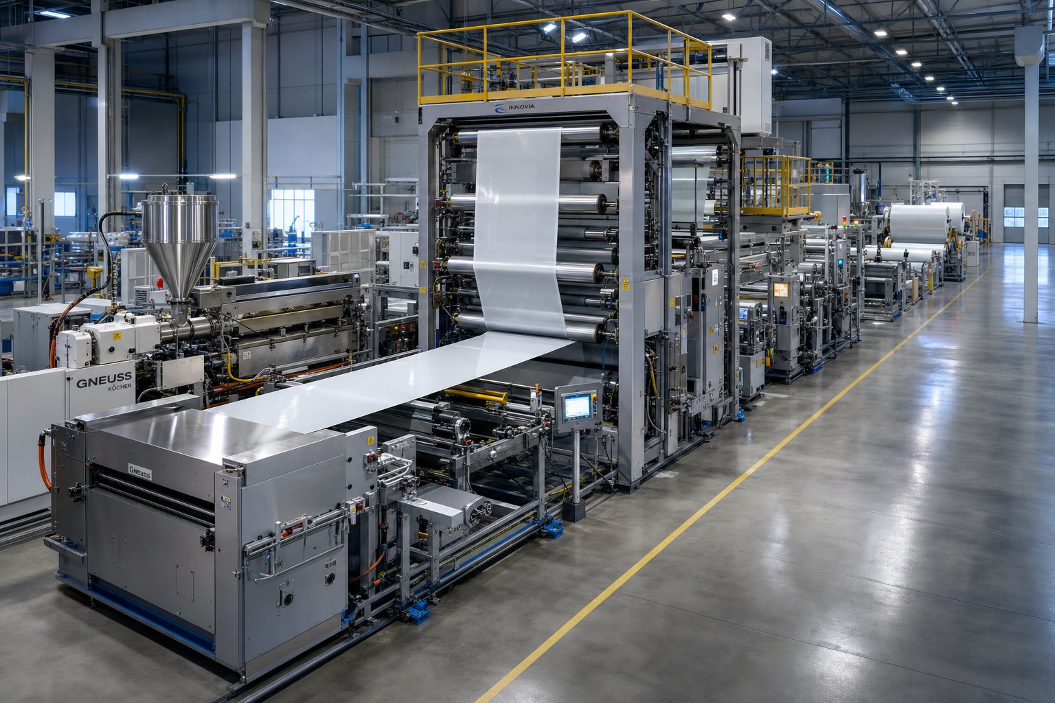
Diagnosing defects, validating quality, and choosing the right process are all critical skills, but they're reactive by nature. The processors who consistently produce flawless sheet at the lowest cost per kilogram take a different starting point: they engineer excellence into the line before the first pellet ever hits the feed throat. Whether you're specifying a brand-new PP sheet extrusion line, upgrading an aging PP PS sheet extrusion line, or reconfiguring a PVC sheet extrusion line for tighter tolerances, the same principle applies: a chain breaks at its weakest link, and every component from the hopper to the stacker must be matched to the target polymer and end-product specification.
Key Takeaways for Sheet Extrusion Success
Every chapter in this guide reinforces a handful of truths that separate high-performing lines from those trapped in a cycle of scrap and troubleshooting:
- Material preparation is non-negotiable. Hygroscopic resins like PET, PC, and ABS must be dried to precise moisture thresholds before processing. Skipping or shortcutting this step triggers hydrolytic degradation, splay, and mechanical property loss that no amount of downstream adjustment can fix.
- Screw and barrel design drives melt quality. The screw's L/D ratio, compression ratio, barrier-flight geometry, and metering-zone depth determine how uniformly the polymer melts and how stable the pressure delivery is at the die. A well-engineered single screw remains the most efficient and cost-effective choice for commodity and engineering polymers processed from pellet form.
- Die geometry must match the polymer's rheology. A coat-hanger manifold with properly tuned choker and restrictor bars distributes melt evenly across the full width. Mismatched die design leads to chronic gauge variation that automated die-bolt systems can only partially compensate for.
- Cooling defines the sheet's final properties. Chill-roll temperatures, nip pressures, and stack configuration control crystallinity, gloss, flatness, and residual stress. Getting these wrong produces sheet that warps, hazes, or cracks during thermoforming.
- Inline QC closes the loop. Continuous thickness scanning with automatic die-bolt feedback, paired with surface inspection cameras, catches deviations in real time rather than after an entire roll has been wound.
Screw and barrel selection is the single highest-leverage decision on any sheet extrusion line. The right combination determines melt homogeneity, output rate, energy efficiency, and ultimately the consistency of every meter of sheet the line produces. Get this pairing wrong, and every downstream station is fighting to compensate.
Action Checklist for Line Optimization
Whether you're commissioning a new line or upgrading an existing one, this five-step sequence keeps every decision anchored to your specific product requirements rather than generic equipment specs:
- Define your target polymer and sheet specification. Pin down the resin family (PP, PET, PS, ABS, PVC, PC, or PETG), target thickness range, width, optical requirements, and downstream converting method (thermoforming, lamination, die cutting, or flat-sheet shipment). Every equipment choice flows from this definition.
- Select the correct screw design and barrel for that material. Match compression ratio, L/D, barrier-flight configuration, and barrel metallurgy to the polymer's melt behavior. A PP sheet line running nucleated homopolymer at high output needs a very different screw geometry than a PVC line processing dry-blend powder at controlled shear. For plants running multiple polymers across sheet, film, pipe, or recycling applications, working with a dedicated screw-and-barrel specialist simplifies the selection process. NANHAIYA's single screw barrel solutions are purpose-built for exactly this range of applications, offering application-matched configurations for PP, PET, PS, ABS, and PVC lines that help ensure reliable melt quality without over-engineering or under-specifying the plasticating unit.
- Choose the right die geometry. Specify a coat-hanger manifold for wide, tight-tolerance sheet. Confirm that flex-lip bolts, choker bars, and zone heaters are compatible with the viscosity range of your target polymer. If you plan to switch between resins frequently, invest in adjustable restrictor bars that accommodate different flow characteristics.
- Configure the cooling stack for your thickness range. A three-roll vertical stack handles most thin-to-medium gauge work. Heavy-gauge board may benefit from a horizontal stack with additional cooling rolls. Set roll temperatures to match the polymer's crystallization window, and verify that each roll holds temperature within ±0.5 °C to prevent gloss variation and curl.
- Implement inline QC from day one. Install a traversing thickness gauge with automatic die-bolt feedback before the first production run, not after the first customer complaint. Add surface inspection cameras and integrate all quality data into the line PLC for real-time visibility and historical traceability.
Partnering with the Right Component Suppliers
A line built from best-in-class individual components can still underperform if those components aren't engineered to work together. The extruder's screw geometry, barrel wear resistance, die flow path, and roll-stack thermal control all interact as a system. When one element is mismatched, whether it's a general-purpose screw running a resin it wasn't designed for or a barrel alloy that wears prematurely under abrasive fillers, the entire line pays the price in lost throughput, elevated scrap, and shortened maintenance intervals.
The most successful sheet processors treat component sourcing as an engineering partnership rather than a purchasing transaction. That means sharing your polymer data, target output rates, and quality specifications with your screw and barrel supplier so they can recommend geometry and metallurgy tailored to your actual process, not a catalog average. It means selecting a die manufacturer who will model flow distribution for your specific resin viscosity curve. And it means specifying roll-stack suppliers who understand how their cooling performance interacts with the polymer's crystallization kinetics.
Sheet extrusion is a mature, proven process, but "mature" doesn't mean "simple." The difference between a line that battles chronic gauge issues and one that hums along shift after shift with Cpk values above 1.67 comes down to deliberate, polymer-informed decisions made at the design stage. Define the product first, match every component to that definition, verify results with real-time data, and continuously refine. That's the formula for turning raw pellets into flawless sheet, consistently and profitably.
Frequently Asked Questions About Sheet Extrusion
1. What is the difference between sheet extrusion and film extrusion?
The primary distinction is thickness. Sheet extrusion produces rigid or semi-rigid flat plastic stock that is typically 0.25 mm (0.010 in) or thicker, cooled on a polishing roll stack. Film extrusion, by contrast, produces flexible material below that threshold using either chill-roll casting or blown-film towers. The downstream equipment, cooling methods, and winding systems also differ significantly. Sheet is often cut into flat blanks or wound loosely for thermoforming, while film is wound tightly onto cores at much higher line speeds.
2. Which polymers are most commonly used in sheet extrusion?
The most widely processed resins include polypropylene (PP) for food packaging and reusable containers, PET for thermoformed clamshells and blister packs, polystyrene (PS) and high-impact polystyrene (HIPS) for disposable trays and cups, ABS for automotive trim and luggage, polycarbonate (PC) for safety glazing and machine guards, PETG for medical packaging and displays, and PVC for credit cards and construction panels. Each polymer requires specific screw geometry, barrel temperature profiles, and chill-roll settings to produce on-spec sheet. Choosing a purpose-built single screw barrel, such as those offered by NANHAIYA at nhyscrews.com, helps ensure optimized melt quality across these different polymer families.
3. Why is resin drying important before sheet extrusion?
Hygroscopic polymers such as PET, PC, ABS, and nylon absorb moisture from ambient air. If processed without proper drying, water molecules trigger hydrolytic degradation at high barrel temperatures, breaking polymer chains and causing splay (silver streaks), bubbles, haze, yellowing, and reduced mechanical strength. Desiccant dryers with dew points at or below -40 degrees Celsius are required to bring moisture content below each resin's critical threshold, for example, below 50 ppm for PET and below 200 ppm for polycarbonate. Skipping this step can turn an entire production run into scrap.
4. How do you fix gauge variation in extruded sheet?
Uneven thickness typically stems from improper die-lip bolt adjustment, inconsistent melt temperature across die zones, worn screw flights that reduce pressure stability, or haul-off speed fluctuations. The most effective remedy is a closed-loop system where an inline traversing thickness gauge, either beta-ray or X-ray, continuously scans the sheet width and feeds real-time data to automatic die-bolt controllers. This approach routinely holds gauge variation below 1% standard deviation. Additionally, verifying that all die-zone heaters and thermocouples are functioning and checking screw flight wear prevents the root causes from recurring.
5. What equipment is needed for a complete sheet extrusion line?
A full production line includes a resin drying and feeding system, a single-screw or twin-screw extruder with application-matched screw and barrel, a screen changer and breaker plate for melt filtration, a flat die (coat-hanger or T-slot design), a three-roll polishing and chill-roll stack, a haul-off unit, an inline thickness scanning gauge, edge trimmers with inline granulators, and either a winder for flexible gauge sheet or a flying shear and stacker for rigid cut-to-length sheet. Each component must be speed-synchronized through a central line-control PLC to maintain consistent gauge and surface quality.
Written by
Nanhaiya Technical Team
Zhoushan Nanhaiya Plastic Machinery Co., Ltd.
The Nanhaiya technical team supports screw and barrel manufacturing projects through application review, technical communication, custom manufacturing coordination, and production and quality control.
Discuss Your Application
Related Articles
More insights on screw barrel technology and plastics processing.

What Nobody Tells You About Screw Barrel For Plastic Machine Design
Oct 10, 2026
Learn how screw barrel for plastic machine design affects melt quality, throughput, and wear life. Covers geometry, resin matching, troubleshooting, and sourcing.
Read Article
Single Screw Extruder for Sheet: Stop Guessing, Start Specifying
Oct 9, 2026
Learn how to specify a single screw extruder for sheet production. Covers screw geometry, resin-specific processing, troubleshooting, and maintenance best practices.
Read Article
PE Pipe Extruder Machine: What Datasheets Won't Tell You
Oct 9, 2026
Learn how a PE pipe extruder machine works, key specs explained, material grade selection, maintenance tips, and buyer guidance beyond the datasheet.
Read ArticleLooking for something else?
Search by material, symptom or product and jump straight to the relevant page.
These are navigation suggestions based on keyword matching — not a quotation, not a delivery commitment, and not a substitute for engineering review. Final specification is confirmed by our engineers against your drawings and processed material.
Need help with screw barrel selection?
Share your machine model, processed material and application. Our team can help with pricing and technical support.