

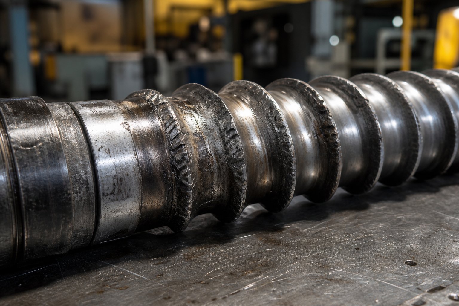
What Screw Wear Looks Like on the Production Floor
Imagine this: your extruder or injection molding machine is running the same resin, at the same settings, on the same tooling — yet output is quietly slipping. Parts come off the line slightly underweight. Melt temperatures drift without any profile changes. Scrap bins fill faster than they should. You troubleshoot the obvious suspects — heater bands, thermocouples, material lot variation — but nothing explains it. The problem isn't in front of you. It's inside the barrel, hidden behind bolted flanges and heat shields, slowly grinding away at your margins.
This is how screw wear announces itself. Not with a dramatic failure, but with a steady erosion of process consistency that operators often attribute to other causes for weeks or even months before the real culprit is identified.
Production Symptoms That Signal Screw Wear
The frustrating reality is that a screw doesn't simply wear out and stop working. Performance degrades gradually, making root-cause identification difficult. You'll notice a cluster of symptoms rather than a single red flag. Watch for these telltale indicators:
- Reduced throughput — the machine produces less material per hour despite unchanged RPM and temperature settings.
- Poor melt homogeneity — unmelted pellets, black specks, or inconsistent viscosity appear in the melt stream.
- Surging — cyclical pressure fluctuations at the die or nozzle that cause dimensional variation in the final product.
- Increased energy consumption — the drive motor draws more current to maintain the same output, a sign the screw can no longer convey material efficiently.
- Color streaking — incomplete distributive mixing leaves visible color concentration differences across parts or profiles.
- Inconsistent part dimensions — shot-weight variation in injection molding or wall-thickness swings in extrusion that exceed normal process capability.
As Santa Fe Machine Works points out, when radial clearance between the screw flights and barrel wall increases, leakage flow occurs — forcing higher RPMs and energy consumption just to maintain the desired production rate. That cascading effect is exactly what makes extruder screw wear so damaging long before anyone pulls the screw for inspection.
Defining Screw Wear in Polymer Processing
Screw wear is the progressive loss of screw flight geometry, surface hardness, and dimensional accuracy caused by the combined effects of mechanical abrasion, chemical corrosion, adhesive metal transfer, and thermal fatigue during polymer processing.
This definition matters because it frames the issue correctly. Screw wear isn't limited to one machine type or one industry sector. Injection molding screw and barrel wear follows the same fundamental mechanisms as degradation in extrusion systems — abrasive fillers erode flight lands, corrosive off-gases attack metal surfaces, and repeated thermal cycling fatigues the base material. The difference lies in where along the screw the damage concentrates and how the process responds.
In extrusion, a worn screw typically shows up as output loss and melt-quality problems. In injection molding, the same degree of flight erosion manifests as shot-weight inconsistency, extended recovery times, and difficulty holding cushion. Both contexts share a critical truth: by the time production data clearly points to the screw, the wear has already been costing you money for longer than you realize.
That financial impact raises an essential question — what exactly is happening at the metal surface to cause this progressive deterioration, and why do certain materials and processing conditions accelerate it so dramatically?
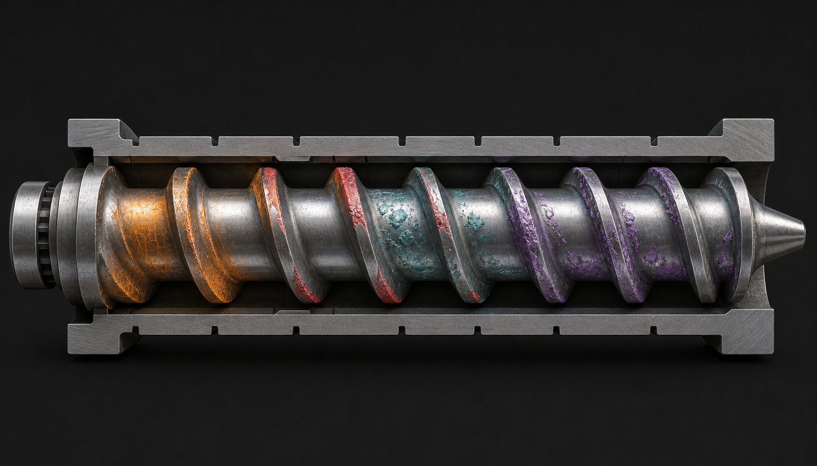
The Four Wear Mechanisms and How They Compound
The symptoms described above — throughput loss, surging, color streaking — all trace back to physical damage at the screw surface. But that damage doesn't come from a single source. Four distinct mechanisms attack your screw simultaneously, and understanding each one is only half the picture. The real insight is recognizing how they feed into each other, creating a compounding cycle that accelerates deterioration far beyond what any single mechanism would cause alone.
Abrasive and Adhesive Wear Mechanisms
Abrasive wear is the most intuitive form of degradation. Hard particles embedded in the polymer melt — glass fibers, calcium carbonate, talc, titanium dioxide, carbon fiber — act like microscopic sandpaper against flight lands and barrel walls. The severity depends on particle hardness, shape, concentration, and processing conditions. Angular particles with sharp edges are far more destructive than rounded ones. According to industry data from Kerke, high-concentration glass-fiber compounds at 30-40% loading can cause flight wear rates of 1.5-3.0 mm per year of continuous operation — enough to push clearances well past tolerance thresholds in a single production cycle.
Here's where it gets worse. Abrasive wear roughens the screw surface at a microscopic level, and that roughened surface sets the stage for adhesive wear on screws. Adhesive wear occurs when the polymer melt bonds to exposed, roughened metal under high shear and temperature. Material accumulates, tears away, and pulls base metal with it — a micro-welding and fracture cycle that pits and gouges the flight surface. Polymers like PVC, polyamide, and certain engineering plastics are especially prone to this adhesion. As Plastics Technology notes, dispersive-mixing sections and barrier flights are particularly vulnerable because resin must flow directly over their geometry under high shear forces.
The critical point is that these two mechanisms are not independent. Abrasive wear creates the surface conditions that amplify adhesive wear. A screw processing glass-filled nylon, for example, suffers abrasive erosion first — and then the resulting surface roughness traps polymer, accelerates adhesion, and compounds the material loss.
Corrosive and Thermal Fatigue Mechanisms
Corrosive wear attacks from the chemical side. Certain resins release aggressive byproducts during processing — PVC generates hydrochloric acid at elevated temperatures, and flame-retardant compounds can off-gas halogenated acids. These chemicals attack the screw metallurgy directly, eating into flight surfaces and root areas. The damage concentrates wherever temperatures and residence times are highest, because elevated heat accelerates chemical reaction rates. What makes corrosive wear especially dangerous is its synergy with mechanical wear: the chemically weakened surface layer offers far less resistance to abrasion, meaning corrosion effectively softens the metal for the abrasive particles to remove.
Thermal fatigue is the least discussed mechanism, yet it contributes to many extruder screw wear issues that operators struggle to explain. Every startup-shutdown cycle subjects the screw to expansion and contraction stress. Frequent production changes that require temperature swings — shifting from a 200°C process to a 280°C process and back — create cumulative micro-cracking on the screw surface. These cracks act as initiation points for all three other mechanisms: abrasive particles lodge in them, corrosive chemicals penetrate deeper, and adhesive forces concentrate along crack edges. Processing high-temperature resins like PEEK or LCP intensifies this effect due to larger thermal differentials.
How Wear Mechanisms Compound Each Other
In real-world production, no screw suffers from just one type of wear. These four mechanisms interact in a self-reinforcing loop — and that compounding effect is what turns a minor tolerance deviation into a serious production problem faster than linear projections suggest. The table below maps each mechanism to its root cause, where it hits hardest on the screw, what it looks like during inspection, and which secondary mechanism it accelerates. This is the relationship pattern that makes high wear screws so costly: damage from one mechanism creates the conditions for the next.
| Wear Mechanism | Primary Cause | Most Affected Screw Zone | Visual Indicators | Secondary Mechanism Accelerated |
|---|---|---|---|---|
| Abrasive | Glass fibers, mineral fillers, pigments, carbon fiber in the polymer | Feed zone (unmelted solids) and transition zone (high pressure) | Uniform flight-tip erosion, reduced OD, scoring on forwarding side of flights | Adhesive wear (roughened surface promotes polymer bonding and micro-welding) |
| Adhesive | Polymer melt bonding to metal under high shear; sticky resins (PVC, PA, engineering plastics) | Metering zone and mixing sections (high shear, full melt contact) | Surface pitting, galling, material buildup and tear-off marks on flight lands | Corrosive wear (pits trap degraded polymer, concentrating chemical attack) |
| Corrosive | Acidic off-gassing from PVC (HCl), flame retardants, halogenated compounds | Transition zone and metering zone (highest temperatures and residence times) | Surface etching, pitting clusters, discoloration, uniform metal thinning in root area | Abrasive wear (chemically softened surface erodes faster under particle contact) |
| Thermal Fatigue | Repeated heating-cooling cycles from startups, shutdowns, and process temperature changes | Transition zone (steepest thermal gradients between solids and melt) | Surface micro-cracking, heat-check patterns, crazing on flight edges | All three mechanisms (cracks provide initiation sites for abrasion, adhesion, and chemical penetration) |
This compounding behavior explains why screw degradation appears to accelerate over time. Early wear is slow and manageable. But once surface roughness, micro-cracking, and chemical attack begin reinforcing each other, the rate of material loss climbs sharply. A screw that took 18 months to reach a monitoring threshold might cross the action threshold just three to four months later — a pattern that catches maintenance teams off guard when they rely on linear wear projections.
The compound effect also means that wear doesn't distribute evenly across the screw length. Different zones experience different dominant mechanisms based on local temperature, pressure, and resin state — a zone-by-zone pattern that reveals exactly where to focus inspection efforts and prevention strategies.
Wear Zone Analysis Across the Screw Length
Each zone of a plasticating screw operates under fundamentally different conditions — different resin states, different pressures, different temperatures. So it shouldn't surprise you that extruder screw and barrel wear doesn't appear uniformly along the screw's length. The damage concentrates in predictable patterns, and knowing where to look first can shave hours off your inspection time and prevent misdiagnosis.
Think of the screw as three distinct environments: the feed zone handles cold, hard pellets under relatively low pressure; the transition zone compresses and melts them under rapidly increasing stress; and the metering zone pumps fully molten polymer at high shear. Each environment creates a different dominant wear signature.
Feed Zone Wear Patterns
The feed zone is where solid pellets first contact the screw surface, and those pellets are anything but gentle. Unmelted granules — particularly glass-filled or mineral-filled compounds — grind against flight tips and the trailing (push-side) edges of each flight with surprising aggression. As Timothy Womer at SpecialChem explains, fillers like mica and fiberglass cause aggressive abrasive damage starting as early as the third and fourth turns of the screw, with erosion extending into the early transition section. The wear appears primarily on the push side of the flight because that's where compacted solids exert the greatest force.
Two operational factors quietly make feed zone wear worse than it needs to be:
- Improper feed throat cooling — when the throat runs too warm, resin begins to soften and stick prematurely. This disrupts smooth solids conveying and creates uneven pressure spikes that press the screw against the barrel wall, accelerating both flight-tip erosion and barrel scoring.
- Neglected hopper magnets — tramp metal particles — bolt fragments, grinder blade chips, even small screws — regularly find their way into hoppers. Without functioning magnets to intercept them, these metal contaminants gouge flight lands and barrel liners, creating immediate damage that compounds with normal abrasive wear from the resin itself.
Because no melt film exists yet in the feed zone to lubricate the pellet-to-metal interface, the raw contact between filler-loaded solids and bare steel is at its most destructive here. Once melting begins downstream, that thin layer of molten polymer cushions the interaction — but in the feed section, there's no such buffer.
Transition Zone and Metering Zone Wear
The transition zone — sometimes called the compression zone — is the highest-stress region on the entire screw. Channel depth decreases rapidly, pressure builds, and the resin undergoes its solid-to-melt phase change. This combination creates conditions ripe for multiple overlapping wear mechanisms.
Compression ratios drive the intensity here. As the channel narrows, unmelted pellets compact against the barrel wall, and any mismatch between screw geometry and resin behavior can force the screw off-center. This phenomenon, known as solids wedging, results in direct metal-to-metal contact between the flight land and barrel bore — the textbook trigger for adhesive wear and galling. Glycon Corp.'s Jeff Kuhman notes that when the melting section's capacity falls short of the feed section's delivery rate, the resulting pressure can physically push the screw against the barrel wall, causing damage to both components simultaneously.
Corrosive gases also concentrate in this region. As polymers like PVC or flame-retardant compounds begin to decompose at elevated temperatures, acidic volatiles become trapped in the partially molten mass. The combination of high temperature, chemical attack, and mechanical stress makes the transition zone the primary failure point for injection molding screw barrel wear in operations processing corrosive resins.
The metering zone, by contrast, handles fully molten polymer at the highest shear rates and melt pressures. Adhesive wear dominates here because the entire screw surface is in constant contact with hot, viscous melt. Sticky polymers bond to the metal under shear, and the repeated attachment-and-tearaway cycle pits the flight surface over time. Mixing elements located within or adjacent to the metering section — Maddock mixers, pineapple tips, and similar designs — experience concentrated adhesive damage because they force polymer through narrow gaps at high velocity.
The table below maps each zone's dominant wear profile, giving you a structured framework for prioritizing inspections and understanding screw barrel wear patterns across the full screw length.
| Screw Zone | Dominant Wear Mechanism | Typical Damage Pattern | Primary Contributing Factors | Inspection Priority |
|---|---|---|---|---|
| Feed Zone | Abrasive wear | Flight-tip erosion, push-side root scoring, reduced OD on forward flights | Unmelted filled pellets, tramp metal, poor feed throat cooling, no hopper magnets | High — check flight OD and root surfaces at turns 3-6 first |
| Transition / Compression Zone | Abrasive + corrosive + adhesive (compound effect) | Galling marks, barrel scoring, root pitting, solids wedging damage | Compression ratio mismatch, corrosive off-gassing, high pressure gradients, thermal fatigue cycling | Critical — highest-stress region; inspect entire circumference for galling and chemical attack |
| Metering Zone | Adhesive wear | Surface pitting, polymer buildup on flights, tear-off marks on mixing elements | High melt shear, sticky resins (PVC, PA, PC), elevated melt temperature, prolonged residence time | Moderate to High — focus on mixing section geometry and flight-land surface condition |
Notice the pattern: the feed zone suffers from raw mechanical aggression, the transition zone absorbs the worst of everything at once, and the metering zone deals primarily with melt-phase adhesion. This zone-specific understanding changes how you approach both scheduled inspections and root-cause analysis. Rather than pulling the entire screw and measuring every flight uniformly, you can focus measurement intensity on the zones most likely to reach threshold clearances first — typically the transition section for corrosive or filled materials, and the feed section for highly abrasive compounds.
Yet the wear patterns described above aren't fixed constants. They shift dramatically depending on screw geometry — compression ratio, flight depth, and overall design philosophy all influence which zone takes the brunt of the damage, and how quickly tolerances degrade.
How Screw Design and Geometry Influence Wear Rates
Here's a question that rarely gets asked early enough: could the screw itself be the reason it's wearing out so fast? The zone-by-zone damage patterns discussed above are real — but their severity isn't determined solely by the resin or the process conditions. The screw's own geometry plays an equally decisive role. A compression ratio that's too aggressive for the material, a flight depth that doesn't match the resin's bulk density, or a design philosophy that concentrates stress where it shouldn't — each of these choices quietly sets the clock on how quickly tolerances degrade. Whether you're evaluating ball screw wear in precision motion systems or flight erosion in a plasticating barrel, the underlying principle holds: geometry dictates where stress concentrates, and stress concentration dictates where material loss begins.
Compression Ratio and Flight Geometry Effects
Compression ratio — the feed channel depth divided by the metering channel depth — is arguably the single most influential design parameter affecting wear rate. When the ratio is properly matched to the resin's bulk density and melting characteristics, solids convey smoothly, pressure builds gradually, and the transition zone operates without excessive mechanical stress. When it's mismatched, problems escalate quickly.
A ratio that's too high for a given resin creates excessive pressure buildup at the end of the transition section. Research published by Dow Inc. comparing five screws with compression ratios ranging from 2.0 to 3.6 on LLDPE demonstrated that screws with ratios above 2.8 generated axial pressures of 4,200 to 5,800 psi near the transition-metering boundary. That pressure forces unmelted solids against the barrel wall, drives the screw off-center, and accelerates flight-tip erosion through direct metal-to-metal contact. The same study confirmed that screws with compression ratios higher than 2.8 cause high flight wear rates at the end of the transition section — exactly the zone already identified as the highest-stress region.
A ratio that's too low presents different problems. The feed section can't deliver enough material to keep the metering channel full and pressurized. The resulting pressure instability leads to surging, inconsistent melt quality, and uneven loading on the screw — which produces eccentric wear rather than the uniform flight erosion you'd see with proper solids conveying.
Flight width and helix angle further modulate wear behavior. Narrower flights concentrate contact pressure on a smaller land area, increasing local stress and erosion rates. Steeper helix angles change the solids conveying dynamics, shifting where peak pressure develops along the barrel. Deeper channels in the feed section boost solids conveying capacity — a benefit for throughput — but they also increase the mass of cold, abrasive pellets grinding against flight surfaces before any melt film forms. Just as calculating wear on a lead screw requires accounting for load distribution across the nut's contact area, predicting flight erosion demands understanding how channel geometry distributes forces across the flight land.
Barrier Screws vs. Metering Screws and Wear Profiles
Screw design philosophy has a profound effect on how and where degradation develops. A conventional general-purpose (GP) metering screw uses a simple three-zone layout — feed, transition, metering — with a single flight. Wear concentrates in predictable zones, primarily the late transition section. Barrier screw designs, by contrast, add a secondary flight in the transition zone that separates the solid bed from the melt pool. This design dramatically improves melting efficiency, but it also introduces a new wear surface: the barrier flight clearance gap.
Because the barrier flight intentionally runs at a tighter clearance to the barrel wall than the primary flight, it's inherently more susceptible to abrasive contact — especially with filled resins. The trade-off is real: barrier screws deliver better melt homogeneity and can reduce metering-zone adhesive wear by delivering a more uniform melt, but they shift abrasive stress onto the barrier flight itself. Operators processing glass-filled materials through barrier designs often see the barrier flight erode faster than the main flight, creating a clearance mismatch that undermines the separation function the design was built to provide.
Mixing elements add another layer of complexity. Maddock-style mixers force polymer through narrow inlet and outlet channels, creating high-velocity flow over small surface areas — ideal conditions for localized adhesive damage. Pineapple and blister-ring mixers experience similar concentrated erosion. In the same way that a brass lead screw nut wear pattern reveals how load and friction interact across a threaded interface, the wear signature on a mixing element tells you exactly where flow forces overwhelm the surface hardness of the metal.
The takeaway is that selecting the correct screw design for the specific resin and application is the single most impactful screw wear prevention measure available — more effective than any coating, alloy, or operational protocol applied after the fact. Before investing in surface treatments or hardfacing, verify that your screw geometry actually matches your processing requirements. Here are the critical design parameters to check:
- Compression ratio — confirm it matches the bulk density and melting behavior of your primary resin; overly aggressive ratios accelerate transition-zone erosion.
- Feed channel depth — deeper channels increase throughput but amplify abrasive contact with unmelted solids; balance capacity against wear rate for filled materials.
- L/D ratio — longer screws provide more barrel surface area for melting and pressure development, reducing the intensity of stress concentration in any single zone.
- Barrier flight clearance — if running a barrier design, verify the clearance hasn't eroded past the point where solid-melt separation is effective.
- Mixing element type and position — match mixer style to the resin's viscosity and shear sensitivity; overly aggressive mixers on heat-sensitive materials cause both degradation and accelerated adhesive wear.
- Flight width and helix angle — narrower flights and non-standard helix angles change pressure distribution and local contact stress; confirm they're appropriate for the application.
Even in applications far removed from polymer processing — such as diagnosing a mini lathe lead screw wearing against lead screw bracket — the same diagnostic logic applies: examine the geometry, identify where contact forces exceed the material's capacity, and address the root cause before treating the symptom.
Getting the geometry right sets the foundation. But even a perfectly designed screw still needs quantitative monitoring to catch degradation before it reaches critical thresholds — which raises a practical question: how do you actually measure flight wear, and what do the numbers mean?
Measuring Screw Wear and Reading Tolerance Thresholds
A perfectly designed screw geometry and a thorough understanding of wear mechanisms won't protect your production if you can't quantify what's actually happening to the metal. The gap between "the screw looks fine" and "the screw measures fine" is where most preventable failures live. Visual inspection catches catastrophic damage — broken flights, deep scoring, obvious galling — but the incremental dimensional loss that quietly degrades output, shot consistency, and melt quality is invisible to the naked eye. You need numbers. And you need to know what those numbers mean against your equipment's specific screw and barrel wear tolerances.
Measurement Tools and Techniques
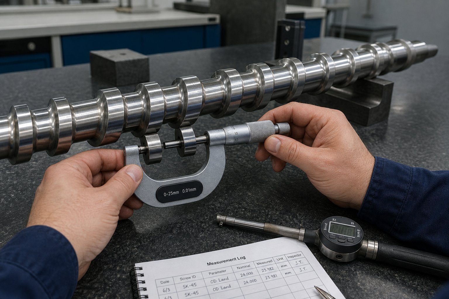
Before you measure anything, preparation matters. Adams Engineers recommends removing all excess resin and placing the screw on a clean, flat work surface. If a granite surface plate is available, roll the screw across it to check for bowing — a bent screw introduces eccentric wear patterns that no amount of flight-land measurement will explain. Use feeler gauges to quantify any bend before proceeding to dimensional checks.
Two primary tools handle the core measurements:
- Outside micrometers — used to measure the screw's outer diameter (OD) across the flight lands. Here's a practical tip: span a precision parallel test bar across two adjacent flights and measure over it. This eliminates the difficulty of seating micrometer anvils directly on narrow, potentially worn flight tips and gives you a repeatable, accurate OD reading.
- Bore gauges (internal micrometers) — used to measure barrel inside diameter (ID). Insert the gauge from each end of the barrel and measure as far down the bore as the tool allows. Record readings at multiple positions to map wear distribution along the barrel length.
For operations that demand higher precision or need to document complex geometry changes — barrier flights, mixing elements, or non-standard profiles — advanced options include:
- Laser scanning — creates a full 3D surface map of the screw, capturing flight geometry, root depth, and surface condition in a single scan. Particularly useful for checking threads on screws for wear across barrier flight sections where clearance changes are critical.
- Coordinate measuring machines (CMM) — deliver micron-level dimensional accuracy for flight width, helix angle, and channel depth. Valuable for forensic analysis when you need to compare a worn profile against original engineering drawings.
Regardless of which tool you use, measurement point selection determines whether your data tells the real story. A single reading per flight can miss localized damage entirely. Best practice calls for a minimum of three measurement points per flight — typically at 0°, 120°, and 240° around the circumference — because screw wear rarely distributes evenly. Eccentric loading, slight barrel misalignment, and non-uniform filler distribution all produce asymmetric erosion patterns. Three-point measurement catches these variations; single-point measurement hides them.
Focus your highest measurement density on the zones identified earlier as most vulnerable: the feed section at turns three through six for abrasive compounds, the full transition zone for corrosive or filled materials, and any mixing elements in or near the metering section. This targeted approach turns a time-consuming inspection into a focused diagnostic exercise.
Interpreting Wear Tolerances and Clearance Thresholds
Raw measurements only become actionable when you compare them against defined tolerance thresholds. The critical dimension is diametral clearance — the difference between the barrel's internal diameter and the screw's outer diameter across the flight lands. This clearance determines leakage flow: as the gap widens, molten polymer flows backward over the flights instead of being conveyed forward, directly reducing output efficiency and melt pressure stability.
Injection molding screw and barrel wear tolerances aren't universal. They vary by screw diameter, barrel metallurgy, resin type, and OEM specification. However, the industry follows well-established general guidelines that provide a reliable reference framework. The table below, built from clearance data published by Santa Fe Machine Works, maps common screw sizes against their nominal new clearance, the monitoring threshold where increased inspection frequency is warranted, and the action-required threshold where continued operation risks significant production losses or component damage.
| Screw Diameter | Nominal New Diametral Clearance | Monitoring Threshold (Worn) | Action-Required Threshold (Max Wear) |
|---|---|---|---|
| 1" (25 mm) | 0.003" – 0.005" | 0.013" – 0.018" | 0.019" – 0.020" |
| 1-1/2" (40 mm) | 0.004" – 0.008" | 0.014" – 0.020" | 0.022" – 0.025" |
| 2-1/2" (60 mm) | 0.005" – 0.010" | 0.016" – 0.021" | 0.028" – 0.030" |
| 3-1/2" (90 mm) | 0.009" – 0.012" | 0.021" – 0.030" | 0.036" – 0.037" |
| 4-1/2" (100 mm) | 0.009" – 0.013" | 0.024" – 0.030" | 0.039" – 0.042" |
| 6" (140 mm) | 0.013" – 0.016" | 0.034" – 0.039" | 0.048" – 0.056" |
| 8" | 0.016" – 0.019" | 0.048" | 0.057" |
| 10" | 0.020" – 0.025" | 0.060" | 0.075" |
Note: These values represent general industry guidelines. Always confirm against your OEM's specifications for your specific equipment, barrel liner material, and processing application. Tolerances for high-performance alloys, bimetallic liners, or specialized applications like acceptable thread wear on aircraft screws follow entirely different — and typically much tighter — standards governed by regulatory frameworks.
Reading this table reveals an important pattern: the monitoring threshold is typically three to five times the nominal new clearance, while the action-required threshold sits only modestly above that. The gap between "new" and "monitor" is wide; the gap between "monitor" and "replace" is narrow. This compression at the upper end reflects a fundamental principle that most operators underestimate:
Screw wear progression is non-linear — the rate of dimensional loss accelerates as clearance increases, because greater leakage flow generates more heat, reduces conveying efficiency, and increases the mechanical forces driving further erosion.
Imagine a screw that took 14 months of continuous operation to move from new clearance to the monitoring threshold. Intuition suggests it should take a proportional amount of time to cross from monitoring to action-required — maybe another six or eight months. In practice, that final phase often compresses to just two to four months. The wider clearance allows more polymer to leak backward over flights, generating frictional heat that softens the screw surface. The softened surface erodes faster under the same abrasive and adhesive forces. More clearance creates more leakage, which creates more heat, which creates more wear — a feedback loop that steepens the degradation curve dramatically once you pass the monitoring zone.
This non-linear acceleration is precisely why trending your measurements over time matters more than any single data point. Adams Engineers emphasizes that the best maintenance programs record measurements at standard intervals to build a wear profile — a historical curve that reveals the component's actual degradation rate rather than relying on generic lifespan estimates. With three or more data points plotted over time, you can project when a screw will cross the action threshold and schedule replacement or repair proactively, avoiding the costly scramble of unplanned downtime.
Knowing exactly where your clearances stand — and how fast they're changing — gives you the data foundation to act. But measurement alone doesn't slow the wear rate. The operational practices surrounding day-to-day processing — material handling, startup sequences, purging discipline — determine whether your screw reaches its full service life or burns through tolerances months ahead of schedule.
Operational Prevention Protocols That Extend Screw Life
Clearance data tells you where your screw stands today. Operational discipline determines where it stands six months from now. The difference between a screw that lasts 18 months and one that reaches 36 months under identical processing conditions almost always comes down to how the machine is handled day to day — not what alloy the screw is made from. Anti wear screw and barrel strategies start with the operator, not the metallurgist.
The protocols below target the root causes of premature degradation directly. Each one addresses a specific mechanism — abrasive, corrosive, adhesive, or thermal fatigue — through practical, repeatable actions that process technicians can implement immediately.
Material Handling and Purging Best Practices
What happens before resin ever touches the screw has an outsized impact on how long that screw lasts. Three material-handling practices, in particular, prevent the most avoidable damage:
Proper resin drying. Moisture in hygroscopic resins like nylon, polycarbonate, and PET doesn't just cause splay defects in parts — it generates corrosive byproducts during processing. When water molecules hit barrel temperatures above 250°C, they accelerate hydrolysis, producing acidic compounds that chemically attack flight surfaces. Running a dryer at the correct temperature and residence time for each specific resin eliminates this hidden corrosion source. Verify dew point readings, not just temperature setpoints, because a dryer that shows the right temperature but delivers poor dew point is still feeding wet material.
Hopper magnet usage. As highlighted in our feed zone analysis, tramp metal is one of the fastest ways to destroy a screw. Reiloy USA's preventive maintenance guidelines emphasize that a single bolt fragment or grinder blade chip passing through the feed throat can score flight lands and barrel liners in minutes — damage that takes months to develop from normal abrasive contact. Inspect and clean hopper magnets at the start of every shift. This five-minute task prevents the kind of catastrophic event that turns a routine production day into an emergency screw pull.
Structured purging schedules. Leaving corrosive or filled resins sitting in the barrel during shutdowns is one of the most common — and most preventable — causes of accelerated degradation. PVC left at processing temperature continues to off-gas hydrochloric acid. Glass-filled compounds left in a cooling barrel create abrasive contact points as the melt solidifies around the screw. Industry best practice calls for purging with a clean, non-corrosive resin or a commercial purging compound (CPC) before every shutdown. Heat-stable CPCs can seal the system during idle periods, preventing oxidation that produces black specks on the next startup. During material transitions, thorough purging also prevents cross-contamination that can generate unexpected chemical reactions between incompatible polymers — another source of corrosive attack that operators often overlook.
Process Parameter Optimization for Wear Reduction
Beyond material handling, how you run the machine matters just as much. Screw speed, back pressure, temperature profiles, and startup sequences all directly influence how fast clearances open up.
Screw speed and back pressure. Higher RPM means higher shear, higher frictional heat, and faster flight-tip erosion — especially with abrasive compounds. Running at the minimum screw speed that delivers acceptable recovery time and melt quality extends component life significantly. Similarly, excessive back pressure forces polymer backward over flight lands at higher velocity, increasing both adhesive contact and frictional heating. Dial back pressure to the lowest setting that still produces a homogeneous melt with consistent shot weight.
Barrel temperature profiling. Flat temperature profiles might seem simpler to manage, but they often force the transition zone to do more work than necessary. A properly ramped profile — gradually increasing from feed to metering — matches the resin's natural melting behavior and reduces the thermal stress that drives fatigue cracking. Avoid sharp temperature jumps between adjacent zones, as steep gradients create localized expansion differentials that accelerate micro-cracking on flight edges.
Startup and shutdown sequences. Cold starts are among the most damaging events a screw experiences. Attempting to rotate the screw before the barrel has reached uniform processing temperature forces flight lands against solidified resin — essentially grinding metal against a rigid polymer plug. Garrett MacKenzie of Plastic411 stresses that verifying temperatures are correct for the material before rotating the screw is essential, as degraded material left in the barrel can even cause screw breakage or barrel lock-up. Follow this startup protocol to minimize cold-start damage:
- Set all barrel zones to the target processing temperature and allow a full heat-soak period — typically 15 to 30 minutes after all zones reach setpoint — before any screw rotation.
- Verify actual temperatures match setpoints on every zone; a failed heater band creates a cold spot that acts as a mechanical anchor against screw movement.
- Begin screw rotation at low RPM (25-30% of normal operating speed) and gradually increase over two to three minutes while monitoring motor current for spikes.
- Purge material through the nozzle and verify the melt stream is clean, free of bubbles, discoloration, or unmelted particles before beginning production.
- Confirm back pressure and screw speed match the validated process setup sheet for the specific resin before transitioning to automatic operation.
For shutdowns, reverse the logic: purge all corrosive or filled material, reduce screw speed gradually, and — if using a heat-stable CPC — seal the barrel before powering down heaters. Never leave the screw sitting in degraded or partially solidified resin overnight.
Daily, Weekly, and Scheduled Prevention Tasks
Consistency is what separates a prevention program from a good intention. The following framework, drawn from structured PM guidelines used in high-OEE molding operations, organizes the key tasks by interval so nothing falls through the cracks:
- Daily / every shift: Inspect and clean hopper magnets. Log barrel zone temperatures (setpoint vs. actual). Check feed throat cooling water flow and temperature. Note any changes in motor current draw, cycle time, or recovery time that could signal increasing clearance.
- Weekly: Clean the feed throat area to remove fines and dust accumulation. Verify dryer performance — dew point, not just temperature. Inspect screw conveyor wear bars, trough liners, and feed system components for material buildup or damage that could introduce contaminants. Confirm purging compound inventory is adequate for the upcoming schedule.
- Scheduled (quarterly or per OEM interval): Perform a full screw pull and dimensional measurement at the zones identified in your wear trending log. Compare current readings to previous measurements and project time to action threshold. Inspect barrel bore with bore gauge, focusing on the transition zone. Evaluate check ring and non-return valve condition. Review and update the PM schedule based on trending data.
Operations running reinforced or corrosive resins should tighten these intervals. Reiloy USA recommends inspecting every six months when processing filled materials until wear trends are established, and annually for unfilled resins. Just as screw conveyor wear strips and screw conveyor trough wear bars are replaced on a scheduled basis in bulk-handling systems to prevent catastrophic conveyor failure, barrel and screw components in polymer processing demand the same proactive attention.
Prevention-oriented operational discipline consistently delivers far greater ROI than reactive repair. Every dollar invested in structured PM prevents roughly $8 to $14 in unplanned repair and lost production costs, according to maintenance cost analyses across mid-sized molding operations. The screw that runs to its full design life isn't the one made from the most exotic alloy — it's the one operated by a team that dries resin correctly, purges on schedule, starts up gently, and measures consistently.
Still, even the best operational discipline can't eliminate wear entirely — it can only slow it. At some point, every screw crosses a threshold where the cumulative production losses from degraded performance begin outweighing the cost of intervention. Recognizing that tipping point requires understanding the hidden economics of running a worn screw — a calculation that most operations have never formally made.

The Hidden Economics of Screw Wear in Production
Most plants treat a worn screw as a maintenance line item — the cost of a new component, plus some downtime to swap it. That framing misses the bigger picture entirely. The real financial damage isn't the replacement itself. It's the weeks or months of degraded performance leading up to that replacement, quietly bleeding margin from every kilogram of resin you process.
Quantifying Production Losses from Screw Wear
As clearance between the screw flights and barrel wall increases, polymer leaks backward over the flights instead of being conveyed forward. This backflow — sometimes called leakage flow — directly reduces conveying efficiency and plasticizing capacity. The loss of extruder output due to screw wear follows a steep, non-linear curve. Industry data from Magog Industries puts it starkly: a 10% decrease in injection screw OD can produce 25% less output. That's not a typo — a seemingly modest dimensional change triggers a disproportionate collapse in throughput.
Consider a real-world throughput test on a single-screw extruder with a 90 mm general-purpose screw running at 135 RPM. The machine produced 228 kg/hr against a manufacturer-rated maximum of 272 kg/hr — a 16% shortfall directly attributable to worn components. That 44 kg/hr gap doesn't just represent lost product. It cascades through the entire operation:
- Longer cycle times — the machine takes more time to deliver the same shot weight or extrusion rate, reducing parts per hour and extending lead times.
- Higher energy consumption per unit — drive motors draw more current to compensate for lost efficiency. Over a 12-month period, even modest overconsumption can add thousands of dollars in electricity costs alone.
- Degraded melt quality — the same leakage flow that reduces output also disrupts melt homogeneity. Material that cycles backward over worn flights absorbs excess shear heat, leading to localized degradation, inconsistent viscosity, and higher scrap rates.
- Increased rework and rejects — dimensional variation, surface defects, and material degradation push defect rates upward, consuming additional labor, material, and machine time to correct.
The compounding nature of these losses is what makes them so insidious. No single symptom looks catastrophic in isolation. A 3% increase in scrap here, a 5% throughput decline there, slightly elevated motor amps — each one gets absorbed into daily variance reports. But aggregated over weeks of continuous operation, they represent a substantial and accelerating drain on profitability.
Building the Business Case for Preventive Investment
Framing the decision correctly changes the math. The question isn't "can we afford to replace the screw?" It's "can we afford not to?" Building an honest business case requires tracking the full cost of degraded performance — not just the repair invoice.
Here are the cost categories every operation should be monitoring once a screw enters the wear-monitoring zone:
- Raw material waste — scrap, purge material, and off-spec product that can't be sold at full value.
- Energy overconsumption — the incremental electricity cost of running higher RPMs and pressures to compensate for lost conveying efficiency.
- Extended cycle times — reduced output per hour multiplied by labor and overhead rates.
- Quality rejects — customer returns, rework labor, and the cost of additional QC inspection triggered by process instability.
- Unplanned downtime — emergency screw pulls, rushed troubleshooting, and the fully loaded downtime costs that typically run two to five times higher than what a work order captures.
- Emergency replacement premiums — rush manufacturing, expedited freight, and premium contractor rates when a failure forces reactive action instead of planned intervention.
When you tally these categories honestly — not just the obvious ones — the total almost always dwarfs the cost of proactive monitoring and timely replacement. The same principle applies across any screw-driven system, whether you're tracking wear on plasticating components, sand screw wear shoes on a classifier, or screw conveyor AR20 wear liners in a bulk-handling operation: deferred maintenance doesn't save money — it just moves the cost somewhere harder to see.
The total cost of running a worn screw typically exceeds the cost of timely intervention within weeks — sometimes days — of crossing tolerance thresholds, because every hour of degraded operation compounds losses across material, energy, quality, and throughput simultaneously.
This economic reality reframes the entire maintenance conversation. The most valuable investment isn't the replacement screw itself — it's the monitoring program that tells you exactly when to act. And when that moment arrives, the next critical decision isn't whether to intervene, but how: choosing the right material, coating, or surface treatment to ensure the replacement or refurbished component delivers maximum service life under your specific processing conditions.
Material Selection and Surface Treatments for Wear Resistance
The economics are clear: running a degraded screw costs more than fixing or upgrading it. But "upgrading" doesn't mean simply buying the hardest metal available. Choosing wear resistant alloys for industrial screws demands matching the surface treatment to your specific resin chemistry, filler loading, processing temperatures, and budget constraints. Get this match wrong, and you'll either overspend on protection you don't need or underspend on protection that fails within months.
The good news? You don't always need a brand-new component. Surface treatment and hardfacing technologies allow operators to restore — and often improve — existing screws with wear-resistant alloy layers, extending service life at a fraction of full replacement cost.
Wear-Resistant Alloys and Surface Treatments Compared
Five mainstream approaches cover the spectrum from basic protection to extreme-duty service. Each carries distinct strengths and trade-offs across hardness, abrasion resistance, corrosion resistance, thermal fatigue tolerance, and cost. The table below maps them side by side so you can identify which direction fits your operation before engaging a supplier.
| Surface Treatment / Alloy | Hardness Range (HRC) | Abrasion Resistance | Corrosion Resistance | Thermal Fatigue Resistance | Typical Applications | Relative Cost Tier |
|---|---|---|---|---|---|---|
| Alloy Spray Welding | 45 – 65 | High | Moderate to High (alloy-dependent) | Good — metallurgical bond absorbs thermal cycling | Restoration of worn screws; upgrading standard screws for filled or corrosive resins; extrusion and injection molding components | Low to Moderate (repair-oriented) |
| Nitrided Steel (e.g., 38CrMoAlA, H13) | 48 – 55 (surface) | Moderate | Low to Moderate | Moderate | General-purpose processing of unfilled PE, PP, PS, ABS | Low |
| Bimetallic Alloy (Ni / Co-based overlay) | 55 – 65 | High | High | Good | Corrosive compounds (PVC, flame-retardant resins), mixed abrasive-corrosive environments | Moderate to High |
| Tool Steel Overlay (D2, SKD61, DC53) | 58 – 62 | High | Moderate | Good — high toughness resists crack propagation | High-compression screws, structural reinforcement of heavily worn zones, WPC and SPC processing | Moderate |
| Tungsten Carbide Coating (WC-Co, WC-Ni) | 60 – 72 | Very High | Moderate (matrix-dependent) | Moderate — brittle under severe thermal shock | Heavily glass-filled compounds (30%+ GF), mineral-filled engineering plastics, high-calcium-carbonate PVC | High |
A few patterns jump out immediately. Nitrided steel — the default for most general-purpose screws — provides adequate protection for unfilled commodity resins but reaches its limits quickly once fillers, corrosive additives, or recycled feedstocks enter the picture. Tungsten carbide coatings sit at the opposite extreme: exceptional abrasion resistance, but higher cost and potential brittleness under thermal shock make them best reserved for the most aggressively filled compounds.
Alloy spray welding occupies a unique position in this lineup. Unlike coatings that sit on top of the base metal with primarily mechanical bonding, spray welding creates a metallurgical bond between the alloy layer and the substrate — producing a dense, strongly adhered surface that resists peeling and spalling under the high pressures and shear forces inside a processing barrel. This bonding characteristic, as hardfacing specialists note, makes metallurgically bonded overlays far more reliable than mechanically bonded thermal spray coatings in heavy-duty, high-stress environments where impact and abrasive erosion are constant.
Matching Materials to Processing Applications
Knowing the properties of each treatment is only useful when you can map them to the resin sitting in your hopper right now. Here's how the most common processing scenarios align with surface treatment choices:
Glass-filled nylons and engineering plastics (15 – 50% GF). These compounds demand high abrasion resistance on flight tips, the transition zone, and any mixing elements. Tungsten carbide coatings or bimetallic overlays with a nickel-cobalt matrix provide the hardness needed to withstand continuous glass-fiber contact. For screws already showing measurable flight erosion, alloy spray welding can restore dimensional accuracy and apply a harder alloy layer than the original nitrided surface — effectively upgrading the screw's wear capability during the repair itself.
PVC compounds. PVC processing combines moderate abrasion from calcium carbonate fillers with aggressive corrosive attack from hydrochloric acid off-gassing. Nitrided steel fails relatively quickly in this environment because the thin nitride layer erodes, exposing base metal to chemical attack. Bimetallic alloys with high nickel content or corrosion-resistant tool steel overlays (SKD61, DC53) offer the dual protection this chemistry requires.
Flame-retardant and halogenated resins. Corrosive wear dominates here. Nickel-based bimetallic alloys — similar in chemistry to Hastelloy or Inconel families — provide the corrosion resistance needed to survive acidic off-gassing without rapid surface deterioration. When existing screws show early-stage corrosive pitting, surface restoration through spray welding with a corrosion-resistant alloy can arrest the damage before it reaches a depth that compromises base metal integrity.
Standard unfilled polymers (PE, PP, PS, ABS). For commodity resins without aggressive fillers or corrosive chemistry, nitrided steel delivers a perfectly adequate service life at the lowest cost. Over-specifying alloy treatments on screws processing clean, unfilled material adds expense without proportional benefit.
The principle is straightforward: match the defense to the threat. Overbuilding wastes capital; underbuilding wastes everything else.
What makes alloy spray welding particularly valuable across these scenarios is its dual role. It's not only a new-build option — it's a restoration method. Operators can take a worn screw that has crossed monitoring thresholds and rebuild it with an alloy layer specifically selected for the resin and filler combination they're processing. This approach converts a screw pull from a pure cost event into an upgrade opportunity. For operations running abrasive or corrosive materials, NANHAIYA's alloy spray welding service provides a practical resource for evaluating surface treatment options tailored to specific processing conditions — allowing operators to restore and enhance components rather than default to full replacement.
The same material-matching logic extends beyond polymer processing into adjacent industries where screw geometry and surface integrity are equally critical. Wear-resistant twin screw pump applications — including wear-resistant twin screw high-viscosity fluids handling and wear-resistant twin screw low-viscosity fluids transfer — rely on many of the same alloy families to protect rotor surfaces against process media. Operators specifying a wear-resistant ATEX twin screw pump for hazardous environments, a wear-resistant twin screw hygienic pump for sanitary service, or equipment for wear-resistant twin screw brewing and wear-resistant twin screw gentle product handling all face the same fundamental question: which alloy and surface treatment will survive the specific combination of abrasion, corrosion, and thermal stress their process demands?
Selecting the right surface treatment sets the technical foundation. But there's still a decision upstream of material choice that many operators struggle with — one that directly determines whether you invest in a coating, a rebuild, or an entirely new component. That decision hinges on the current condition of both the screw and the barrel, and it follows a framework far more nuanced than simply measuring clearance and writing a purchase order.
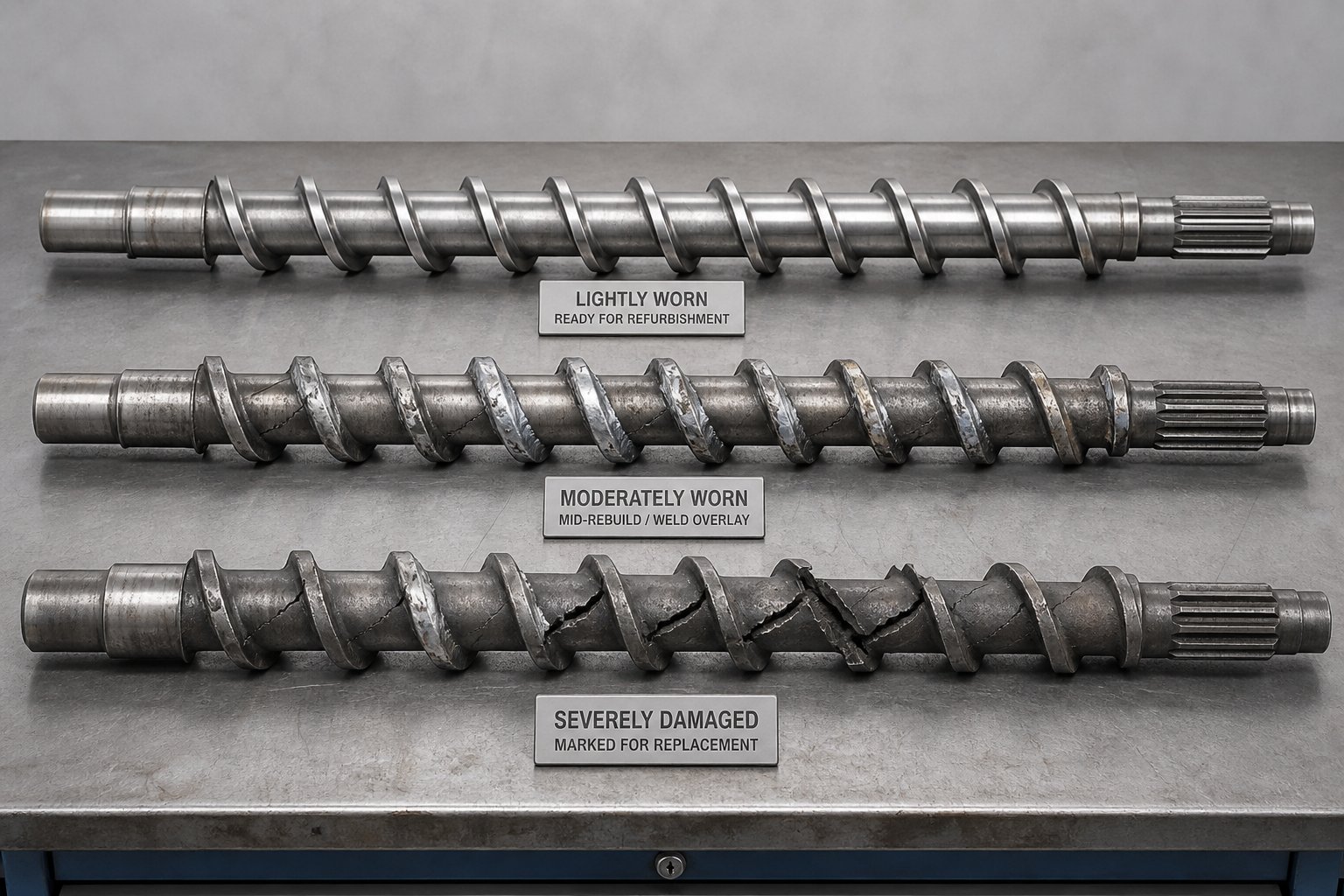
The Refurbish, Repair, or Replace Decision Framework
You've measured the clearances, identified the wear zones, and tallied the production losses. The screw is worn — that much is certain. The question staring you down right now isn't whether to act, but how. Do you refurbish what you have, repair the damaged sections, or scrap the component and order new? Each path carries different costs, different timelines, and different implications for long-term performance. Choose wrong, and you either overspend on a replacement you didn't need or invest in a repair that fails within months.
Most operations default to one of two extremes: run the screw until it catastrophically fails, or replace it at the first sign of trouble. Both approaches waste money. A structured decision framework — one that maps wear severity to the right intervention level — consistently delivers the best hard wearing precision screw sets and the lowest total lifecycle cost.
When to Refurbish, Repair, or Replace
The decision matrix below connects your measurement data directly to an action plan. Four severity levels — from "within tolerance" through "beyond repair" — each correspond to a specific intervention, a relative cost range, and a realistic expectation for restored service life. Think of it as a diagnostic flowchart built from the tolerance thresholds discussed earlier.
| Wear Severity Level | Clearance Status | Recommended Action | Typical Methods | Relative Cost (vs. New) | Expected Restored Service Life |
|---|---|---|---|---|---|
| Within Tolerance | Below monitoring threshold | Continue operation with scheduled monitoring | Routine dimensional checks per PM schedule; trend data logging | Minimal (inspection labor only) | Full remaining design life |
| Monitoring Zone | Between monitoring and action thresholds | Surface restoration and dimensional rebuild | Alloy spray welding or hardfacing on flight tips; polishing; re-nitriding | 20% – 40% | 60% – 100%+ of original life (alloy-dependent) |
| Action Threshold | At or beyond action-required limit | Screw rebuilding or major repair | Full flight rebuild via weld overlay; channel re-machining; base metal assessment required | 40% – 65% | 50% – 80% of original life |
| Beyond Repair | Severe structural damage — cracking, excessive base metal loss, distortion | Full replacement | New screw manufacture to OEM or upgraded specification | 100% | Full new design life |
Two rows in this table deserve special attention. The "monitoring zone" intervention — surface restoration via spray welding or hardfacing — is where operators capture the highest return on investment. At this stage, the base metal is still structurally sound, and only the working surface needs rebuilding. Hardfacing cost analyses across industrial components consistently show that rebuilding only the worn surface reduces maintenance costs by 30% to 70% compared to full replacement, while extending service life by two to five times. That same principle applies directly to plasticating screws: catching wear in the monitoring zone and applying a wear-resistant alloy overlay is almost always more economical than waiting for the action threshold and facing a major rebuild or replacement.
The "beyond repair" level, by contrast, is non-negotiable. When inspection reveals fatigue cracking through the flight root, significant base metal distortion, or dimensional loss so severe that rebuilding would leave insufficient substrate, replacement is the only safe path. As Nan Yun Industrial's refurbishment guide points out, not all components benefit from refurbishment — excessive damage can render repair ineffective or even counterproductive. A reputable supplier will tell you when a screw has passed the point of economic repair rather than performing work that won't hold up in service.
Making the Right Intervention Decision
Clearance measurements alone don't tell the whole story. Several factors beyond simple dimensional data influence whether a refurbishment, repair, or replacement delivers the best outcome for your specific situation.
Barrel condition. Screw and barrel wear are interdependent — you can't evaluate one without the other. Installing a restored screw into a worn barrel is like putting new tires on bent rims. If the barrel bore has gone oval or expanded past its own tolerance threshold, the rebuilt screw will wear asymmetrically and lose dimensional accuracy far faster than expected. Always measure barrel ID alongside screw OD, particularly in the transition zone where both components take the heaviest abuse. American Kuhne news tech tips on extruder screw and barrel wear consistently emphasize this paired-assessment approach: treating the screw and barrel as a system rather than independent components.
Remaining base metal integrity. Surface treatments like alloy spray welding and hardfacing bond to the existing substrate. If the base metal has been weakened by years of thermal fatigue cycling, suffered hydrogen embrittlement from corrosive processing, or lost significant cross-sectional area in the flight root, the overlay may not adhere reliably or may crack under operational stress. Non-destructive testing — dye penetrant, magnetic particle, or ultrasonic inspection — can reveal subsurface defects that visual examination and dimensional measurement miss entirely.
Processing demands going forward. Are you planning to switch from an unfilled resin to a 30% glass-filled compound? Are you adding flame-retardant grades to your material portfolio? The right intervention isn't just about restoring what you had — it's about preparing for what's coming. A screw that was adequate in nitrided steel for unfilled polypropylene may need a bimetallic overlay or tungsten carbide flight tips to survive your next product line. Repair-oriented surface restoration lets you upgrade metallurgy during the rebuild, effectively converting a maintenance event into a capability improvement.
Production schedule constraints. A full screw replacement from a custom manufacturer can take four to twelve weeks depending on size, complexity, and queue position. If your production schedule can't absorb that lead time, a well-executed surface restoration — often completed in days rather than weeks — keeps the line running while delivering performance close to a new component. The lead screw wear brass nut vs. steel nut trade-off in precision motion systems illustrates the same principle: sometimes the faster, more accessible repair path delivers better total value than waiting for the theoretically optimal solution.
For operators processing abrasive or corrosive materials who need an expert assessment of their screw and barrel condition, NANHAIYA's alloy spray welding service offers a specialist resource for surface treatment and dimensional restoration. Their approach focuses on evaluating whether existing components can be rebuilt with enhanced wear-resistant alloys — a repair-first philosophy that avoids unnecessary full replacement when the base metal still has serviceable life remaining.
The most cost-effective intervention decision depends on evaluating total lifecycle cost — including downtime, lead time, remaining barrel condition, and future processing demands — not just the upfront price of a new screw versus a repair invoice.
This lifecycle perspective is what separates reactive maintenance from strategic asset management. A data-driven repair vs. replace analysis considers equipment age, historical maintenance costs, remaining useful life, and the total cost of ownership across all options — not just whether a repair is cheaper than a purchase order today. The forklift transmission analogy scales directly to plasticating screws: a $4,000 repair that extends life by three years may deliver far better ROI than a $35,000 replacement, but only if the underlying structure supports it.
Every screw eventually reaches its end of life. The goal isn't to avoid replacement forever — it's to extract maximum value from every component by intervening at the right time, with the right method, using the right materials. Measure consistently. Trend your data. Assess screw and barrel as a paired system. And when the numbers say it's time to act, choose the intervention level that minimizes total lifecycle cost — whether that's a targeted surface restoration, a full rebuild, or a new component engineered for the next chapter of your production demands.
Frequently Asked Questions About Screw Wear
1. What are the early signs that my extruder or injection molding screw is worn?
The earliest indicators typically appear as subtle process shifts rather than obvious failures. Watch for gradual throughput decline at unchanged RPM settings, shot-weight variation beyond normal process capability, increased motor amperage draw, and melt-quality issues like color streaking or unmelted particles. Surging — cyclical pressure fluctuations at the die or nozzle — is another reliable warning sign. Because these symptoms overlap with other process issues such as heater band failures or material lot variation, many operators misattribute them for weeks before identifying screw wear as the root cause. Trending motor current draw and recovery time over multiple production runs is one of the fastest ways to isolate screw-related degradation from other variables.
2. How do you measure screw wear and what clearance thresholds require action?
Screw wear is quantified by measuring diametral clearance — the gap between the screw's outer diameter (measured with outside micrometers) and the barrel's inner diameter (measured with bore gauges). Best practice calls for at least three measurement points per flight at 0, 120, and 240 degrees to catch asymmetric erosion. For a typical 90 mm screw, nominal new clearance falls between 0.009 and 0.012 inches, with a monitoring threshold around 0.021 to 0.030 inches and an action-required threshold at 0.036 to 0.037 inches. Critically, wear progression is non-linear — once clearance enters the monitoring zone, degradation accelerates because greater leakage flow generates more frictional heat, softening the metal surface and compounding erosion. Always confirm against your OEM specifications, as tolerances vary by diameter and barrel liner material.
3. What causes screw wear to accelerate so quickly after initial degradation?
Four wear mechanisms — abrasive, adhesive, corrosive, and thermal fatigue — interact in a self-reinforcing cycle that explains the non-linear acceleration. Abrasive wear from filled resins roughens the screw surface at a microscopic level, which then promotes adhesive wear as polymer bonds to and tears away from the roughened metal. Adhesive pitting traps degraded polymer, concentrating corrosive chemical attack. Thermal fatigue from startup-shutdown cycles creates micro-cracks that serve as initiation points for all three other mechanisms. This compounding behavior means a screw that took 14 months to reach a monitoring threshold might cross the action-required threshold in just three to four months — catching maintenance teams off guard if they rely on linear wear projections.
4. Should I refurbish a worn screw or replace it entirely?
The answer depends on wear severity, base metal integrity, barrel condition, and future processing demands. Screws in the monitoring zone — where the surface is worn but the base metal is structurally sound — are ideal candidates for surface restoration through alloy spray welding or hardfacing, typically costing 20 to 40 percent of a new screw while restoring 60 to 100 percent of original service life. Screws at the action threshold may need full flight rebuilds at 40 to 65 percent of replacement cost. Only screws with severe structural damage — cracking, distortion, or excessive base metal loss — require full replacement. Services like NANHAIYA's alloy spray welding (nhyscrew.com/services/alloy-spray-welding) can assess whether existing components can be rebuilt with enhanced wear-resistant alloys, avoiding unnecessary full replacement when the substrate still has life remaining.
5. How can I extend the service life of my plasticating screw?
Operational discipline delivers more screw life extension than any alloy upgrade applied after the fact. Three high-impact practices include proper resin drying to eliminate moisture-driven corrosive byproducts, consistent hopper magnet inspection every shift to intercept tramp metal, and structured purging with a clean resin or commercial purging compound before every shutdown. On the process side, running at the minimum screw speed that delivers acceptable recovery time reduces abrasive erosion, while a properly ramped barrel temperature profile — gradually increasing from feed to metering — minimizes the thermal fatigue that drives micro-cracking. Never cold-start a screw; always allow a full heat-soak period and begin rotation at low RPM. Combined, these protocols can double or triple service life compared to reactive maintenance approaches.
Written by
Nanhaiya Technical Team
Zhoushan Nanhaiya Plastic Machinery Co., Ltd.
The Nanhaiya technical team supports screw and barrel manufacturing projects through application review, technical communication, custom manufacturing coordination, and production and quality control.
Discuss Your Application
Related Articles
More insights on screw barrel technology and plastics processing.

What Nobody Tells You About Screw Barrel For Plastic Machine Design
Oct 10, 2026
Learn how screw barrel for plastic machine design affects melt quality, throughput, and wear life. Covers geometry, resin matching, troubleshooting, and sourcing.
Read Article
Single Screw Extruder for Sheet: Stop Guessing, Start Specifying
Oct 9, 2026
Learn how to specify a single screw extruder for sheet production. Covers screw geometry, resin-specific processing, troubleshooting, and maintenance best practices.
Read Article
PE Pipe Extruder Machine: What Datasheets Won't Tell You
Oct 9, 2026
Learn how a PE pipe extruder machine works, key specs explained, material grade selection, maintenance tips, and buyer guidance beyond the datasheet.
Read ArticleLooking for something else?
Search by material, symptom or product and jump straight to the relevant page.
These are navigation suggestions based on keyword matching — not a quotation, not a delivery commitment, and not a substitute for engineering review. Final specification is confirmed by our engineers against your drawings and processed material.
Need help with screw barrel selection?
Share your machine model, processed material and application. Our team can help with pricing and technical support.