

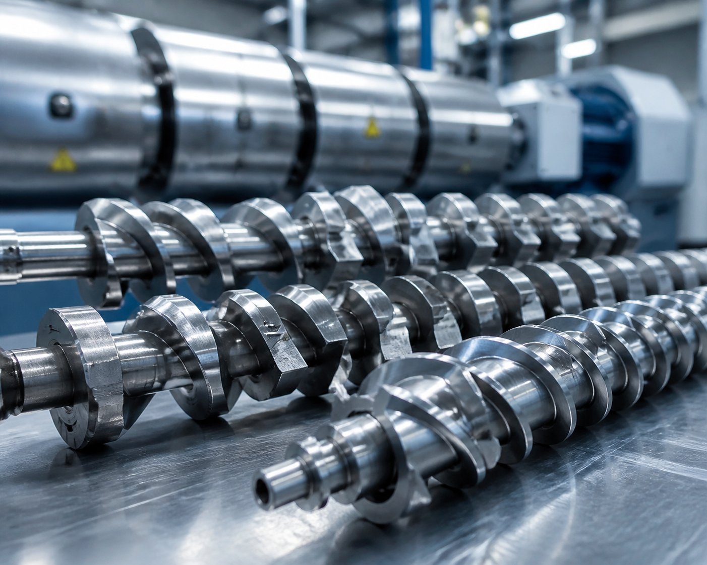
What Is a Screw Segment and Why It Matters
Imagine trying to optimize five different processing zones inside your extruder, but you're locked into a single, unchangeable screw design. Every recipe change means buying an entirely new screw. Every worn-out section means scrapping the whole assembly. That's the reality without modular screw segment design — and it's exactly the limitation that segmented screws were engineered to eliminate.
What Exactly Is a Screw Segment
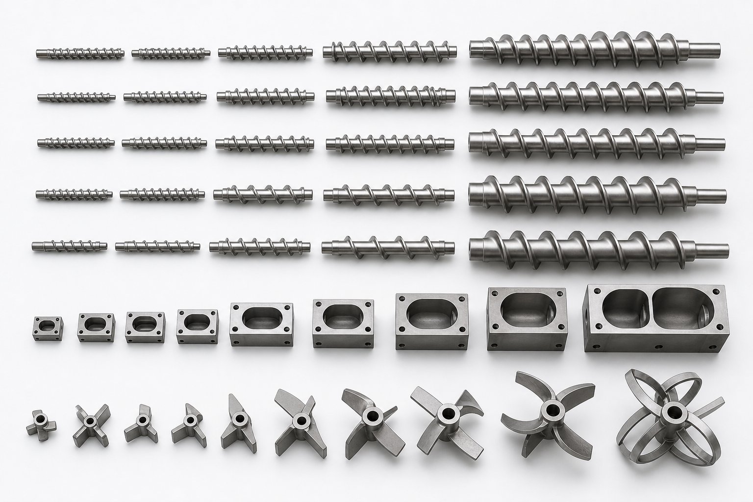
A screw segment is a discrete, replaceable element that slides onto a splined shaft to form part of a complete screw profile inside an extruder. Rather than machining the entire screw as one continuous piece of metal, segmented designs break it into individual components — conveying elements, kneading blocks, mixing elements, and more — that lock together along the shaft through a keyway or spline connection.
This modular approach is the standard in segment twin screw extruders, where two co-rotating or counter-rotating screws work in parallel. Each element along the shaft performs a specific task: feeding raw material, building pressure, melting, mixing, venting, or pushing the final melt toward the die. You can rearrange, swap, or replace any individual piece without touching the rest of the assembly. The result? One extruder becomes adaptable to dozens of different materials and processes simply by reconfiguring the elements on the shaft.
Why Segmented Screw Design Exists
The engineering rationale behind screw segment design comes down to three forces that shaped modern extrusion: the demand for processing flexibility, the economics of maintenance, and the need for zone-by-zone optimization.
Early extruders relied on monolithic screws — single-piece shafts machined with a fixed flight geometry from feed throat to discharge. They worked, but they were rigid. If a processor needed to switch from compounding glass-filled nylon to blending a soft thermoplastic elastomer, the screw geometry that worked for one material would produce terrible results with the other. Changing processes meant changing the entire screw, which was expensive and time-consuming.
Segmented designs, built on the self-wiping Erdmenger geometry patented in the late 1950s, solved this by treating each processing zone — feeding, melting, mixing, conveying, and devolatilization — as an independent, tunable section. Wear concentrated in the high-shear mixing zone? Replace just those kneading blocks. Need stronger dispersive mixing for a new filler? Swap in more aggressive elements at that position alone.
Segmented screw design revolutionized polymer processing by transforming the extruder screw from a fixed, single-purpose tool into a modular, reconfigurable system — allowing processors to independently optimize every functional zone without replacing the entire assembly.
Key Geometric Parameters at a Glance
Every screw segment is defined by a handful of geometric parameters. Understanding these is essential because each one directly controls a specific aspect of how material behaves inside the barrel. Here's what you'll encounter when evaluating or specifying elements:
- Pitch — The distance between two consecutive flights. A wider pitch moves material faster with less shear; a tighter pitch builds more pressure and increases residence time.
- Flight thickness — The width of the helical ridge. Thicker flights are more durable but reduce the available channel volume for material flow.
- Channel depth — The distance from the flight tip down to the screw root. Deeper channels increase the volume of material conveyed per revolution, while shallower channels intensify shear input.
- Helix angle — The angle of the flight relative to the screw axis. It influences both conveying efficiency and the balance between axial transport and cross-channel flow.
- Outer diameter (OD) and inner diameter (ID) — The OD defines the flight tip circle and the clearance with the barrel wall, while the ID (root diameter) sets the channel depth. The ratio between them — often called the OD/ID ratio — is a defining characteristic of the extruder platform and determines the available free volume.
These parameters don't operate in isolation. A deep-channel conveying element with wide pitch behaves very differently from one with a tight pitch and shallow channel, even if they share the same outer diameter. It's the interplay between these dimensions that determines whether a given element gently transports material forward or aggressively compresses and shears it.
Of course, understanding individual geometry only tells part of the story. The real performance question is how segmented assemblies stack up against their monolithic counterparts — and where each design truly earns its place on the production floor.
Segmented vs. Monolithic Screw Design Compared
A monolithic screw and a segmented assembly can look surprisingly similar once installed inside a barrel. Both rotate, both convey polymer, and both produce extrudate at the die. So why does the choice between them matter so much — and why does picking the wrong one quietly erode your throughput, your flexibility, and your bottom line?
How Monolithic Screws Differ from Segmented Assemblies
A monolithic screw is machined from a single steel billet. The flight geometry — every channel, every transition, every compression zone — is cut directly into one continuous shaft. There's an elegant simplicity to this approach: fewer parts, no spline connections to maintain, and no risk of element misalignment. Single screw extruders overwhelmingly use this design because their processing demands are relatively fixed.
Segmented assemblies flip that logic entirely. Individual screw segment elements slide onto a common splined shaft, each one performing a targeted function at a specific barrel position. Need to change your mixing intensity? Swap a few kneading blocks. Dealing with accelerated wear at one location? Replace only those elements. The rest of the assembly stays untouched.
Here's how the two architectures compare across the dimensions that matter most on the production floor:
| Criteria | Monolithic (Single-Piece) Screw | Segmented Screw Assembly |
|---|---|---|
| Flexibility | None — geometry is permanently fixed at machining | High — elements can be rearranged, swapped, or replaced individually |
| Maintenance Cost | High — entire screw must be replaced or re-machined when worn | Lower — only worn segments need replacement |
| Customization Potential | Zero post-manufacture customization | Virtually unlimited reconfiguration options |
| Typical Extruder Type | Single screw extruders | Co-rotating and counter-rotating twin screw extruders |
| Replacement Approach | Full screw replacement | Individual element replacement at wear points |
The contrast is stark. A monolithic screw locks you into one processing profile for its entire service life, while a segmented design treats the screw as a reconfigurable tool that evolves with your product mix.
Segment Screw Flight vs Continuous Screw Flight
The functional differences go deeper than just maintenance convenience. When you compare a segment screw flight vs a continuous screw flight, you're really comparing two fundamentally different philosophies of process control.
A continuous flight — the helical ridge running uninterrupted along a monolithic screw — provides uniform conveying behavior from one end to the other. Material moves forward at a consistent rate dictated by a fixed geometry. That uniformity works well for simple, single-material extrusion tasks, but it becomes a significant limitation the moment you need zone-by-zone optimization. You can't independently adjust mixing intensity in one barrel section without affecting everything upstream and downstream.
Segmented flights solve this by treating each barrel zone as a distinct processing station. One position might use wide-pitch conveying elements for rapid material transport. The next might feature tight-pitch elements that build pressure and increase fill level. A kneading block section can deliver intense shear for filler dispersion, immediately followed by deep-flighted elements designed for devolatilization. Each transition is deliberate, and each element is selected to match the specific processing demands of its location.
A critical concept here is free volume — the open space available inside the channel between the flight tips and the screw root. Free volume determines how much material each element can physically accommodate per revolution. Elements with generous free volume handle high throughput and provide ample surface exposure for degassing. Elements with restricted free volume intensify shear and compression. In a segmented design, you control free volume position by position, directly tuning throughput capacity and mixing efficiency along the entire barrel length. With a monolithic screw, the free volume profile is fixed permanently at manufacturing.
This distinction explains why a sectional screw flight or segment screw flight description from any reputable manufacturer will always reference the element's pitch, length, and OD/ID ratio — because these parameters define the local free volume and, by extension, the processing behavior at that specific position.
When Segmented Design Becomes Essential
Not every extrusion operation needs the modularity of segmented screws. A dedicated line running the same polyethylene blend year after year may perform perfectly well with a monolithic design. But several scenarios make segmented assemblies not just preferable — but essential:
- Multi-product facilities — When a single extruder must process different polymers, fillers, or formulations across production campaigns, segmented designs let you reconfigure the screw profile to match each recipe without purchasing entirely new screws.
- Frequent recipe changes — Applications like color masterbatch production or custom compounding demand rapid adjustments to mixing intensity and residence time. Swapping a handful of elements is far faster and cheaper than machining a new monolithic screw.
- Zone-specific wear patterns — Abrasive fillers like glass fiber or calcium carbonate concentrate wear in the mixing zones where shear forces peak. Segmented assemblies from companies producing segmented continuous uniform-thickness screw blades allow you to replace only the damaged elements, extending the functional life of the entire shaft assembly.
- Precise shear and thermal history control — Heat-sensitive polymers, reactive extrusion processes, and pharmaceutical applications all require tight control over how much mechanical energy the material absorbs at each stage. Only a modular configuration offers the granularity to fine-tune shear input zone by zone.
In practice, the decision often comes down to operational versatility. If your production environment is static and predictable, monolithic simplicity has merit. The moment your process demands adaptability — different materials, changing specifications, wear-driven maintenance, or precise thermal management — segmented elements become the only architecture that keeps throughput stable without constant capital expenditure on new screws.
The choice between these two design philosophies naturally raises the next question: once you've committed to a segmented approach, which types of elements do you actually have at your disposal, and what does each one do inside the barrel?
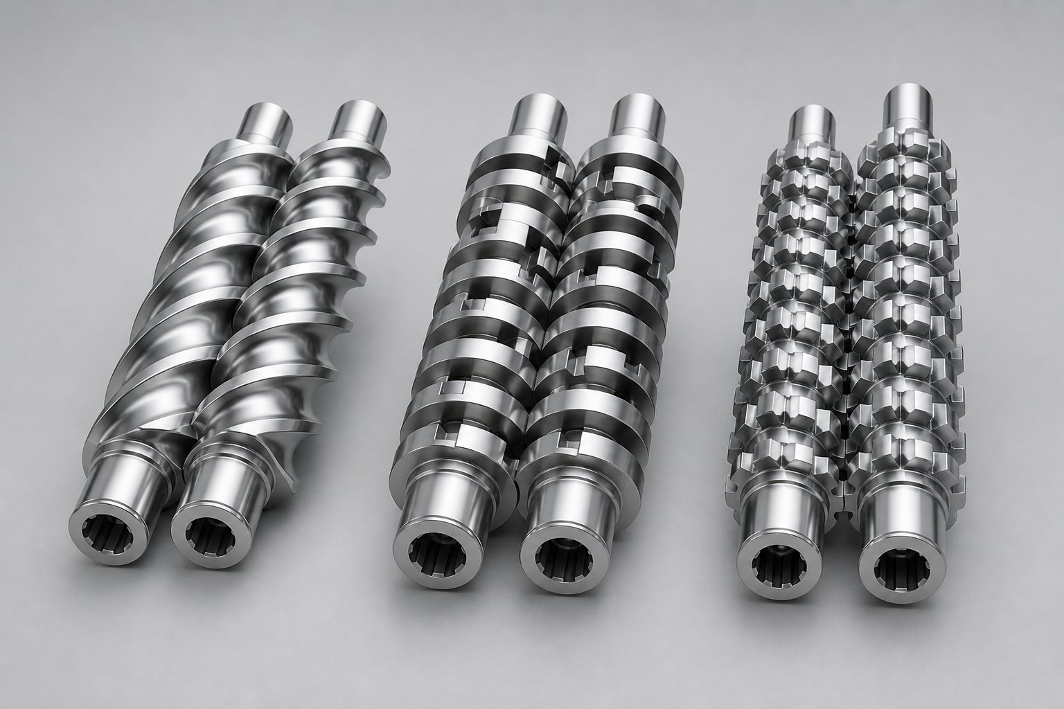
Types of Screw Segments and Their Functions
Every extruder screw segment on a twin screw shaft falls into one of a few fundamental categories — but within those categories, subtle geometry differences produce dramatically different processing results. Choosing the wrong element type for a specific barrel position is one of the fastest ways to silently destroy throughput, degrade product quality, or accelerate wear. Understanding what each type actually does inside the barrel is what separates efficient compounding from guesswork.
Conveying Screw Elements and Their Variations
Conveying elements are the workhorses of any segmented screw elements for twin extruder configurations. They feature a continuous helical flight — typically a two-lobed (bilobal) profile on co-rotating machines — and their primary job is transporting material forward along the barrel. But don't let the word "conveying" suggest these elements are simple or interchangeable. The pitch of a conveying element fundamentally changes its behavior.
A wide-pitch conveying element moves material quickly with minimal pressure buildup. You'll find these in feed zones and devolatilization sections, where the goal is to keep fill levels low and provide maximum open surface area for gas escape. A tight-pitch element, by contrast, restricts forward flow, increases channel fill, and builds significant pressure. These are positioned near the die end or upstream of mixing zones to ensure material is packed tightly enough for effective processing downstream.
Here are the most common conveying element subtypes you'll encounter:
- Wide-pitch forward elements — High conveying rate with low shear; used in feed zones, vent zones, and transitions where gentle material transport is needed.
- Standard-pitch forward elements — Balanced conveying and moderate pressure generation; the general-purpose choice for most barrel positions.
- Tight-pitch forward elements — Reduced throughput per revolution but significantly higher pressure buildup and channel fill; used in metering sections and pre-mixing zones.
- Reverse-pitch (left-handed) elements — Push material backward against the main flow, creating a pressure seal and dramatically increasing residence time at that position. Essential for melt seals upstream of vent ports and for intensifying fill in mixing zones.
The pitch ratio — the element's pitch divided by the screw diameter — directly governs fill level and conveying efficiency. A ratio above 1.0 produces rapid, low-fill transport. A ratio below 0.5 generates heavy fill and strong pressure. Reverse elements effectively create a ratio of negative value, acting as restrictive dams that force material to accumulate upstream. This accumulation is precisely what enables the mixing and devolatilization zones flanking them to function properly.
Kneading Blocks and Mixing Intensity
If conveying elements are the transportation network, kneading blocks are the processing engines. These are the elements responsible for the actual mixing work — dispersing fillers, breaking down agglomerates, homogenizing polymer blends, and melting solid pellets through intense shear.
Structurally, a kneading block consists of a series of elliptical disc-like lobes stacked along the shaft, each offset from the previous one by a fixed stagger angle. As the screw rotates, material is squeezed between these offset lobes and the barrel wall, experiencing high elongational and shear forces. The stagger angle between adjacent discs is the single most important variable controlling what type of mixing a kneading block delivers.
Here's how stagger angle maps to mixing behavior:
- 30° stagger (forward) — Provides gentle distributive mixing while still conveying material forward. Material passes through the kneading zone relatively quickly, experiencing moderate shear. Best for applications where you need to spread additives evenly without breaking them down aggressively.
- 60° stagger (forward) — Delivers moderate dispersive mixing with reduced forward conveying action. Material spends more time in the kneading zone and encounters higher shear stress. This is the workhorse angle for general-purpose compounding of filled polymers.
- 90° stagger (neutral) — Produces maximum shear and the strongest dispersive mixing effect with zero forward conveying. Material must be pushed through entirely by upstream pressure. Residence time and shear stress peak at this configuration, making it ideal for breaking down tough agglomerates or achieving fine dispersion of mineral fillers like talc and calcium carbonate.
The distinction between distributive mixing and dispersive mixing is critical to understand here. Distributive mixing spreads materials evenly throughout the matrix — imagine stirring cream into coffee until the color is uniform. Dispersive mixing, on the other hand, applies enough force to physically break down particle clusters, droplets, or agglomerates into smaller pieces. Most real-world compounding applications need both, which is why mixing zones typically combine kneading blocks of different stagger angles in sequence.
Research from Paderborn University's 3D CFD flow simulations with particle tracking confirmed that kneading block geometry and rotation speed both significantly influence mixing outcomes. Their analysis showed that a 90° kneading block (KB24) achieved better distributive mixing than a 45° block (KB45) under identical process conditions — with the KB24 reaching a mixing quality index (MQ) of 0.92 versus 0.99 for the KB45 at 400 rpm. Lower MQ values indicate more homogeneous particle distribution, meaning the tighter stagger angle produced measurably better uniformity.
The number of kneading discs also matters. More discs within a single block increase the total shear exposure time for material passing through. Shorter disc lengths with gaps between them generally improve distributive mixing performance, while longer discs intensify dispersive action. It's a balancing act — too many aggressive kneading discs in sequence can overshear the polymer, causing degradation and discoloration, while too few leave fillers poorly dispersed.
Specialty Segments for Advanced Processing
Beyond conveying elements and kneading blocks, the twin screw extruder segment barrel hosts a family of specialty elements designed for niche but important processing tasks. These elements often fly under the radar, yet they can solve mixing problems that standard kneading blocks simply cannot address.
Toothed mixing elements (TME or ZME) are among the most versatile. Instead of continuous helical flights or offset lobes, these elements feature rows of teeth that intermesh between the two screws. The result is a fundamentally different flow pattern: material is repeatedly divided, reoriented, and recombined as it passes through the tooth gaps. This produces excellent distributive mixing at relatively low shear stress — a combination that standard kneading blocks struggle to achieve.
The Paderborn University study found that toothed mixing elements (ZME) consistently outperformed all tested kneading block configurations for distributive mixing quality. At 200 rpm, the ZME achieved an MQ value of approximately 1.17, compared to 2.38 for a short kneading block (KB12) under the same conditions. Even more notably, the ZME also generated high shear stresses for many particles — delivering strong dispersive mixing simultaneously. The frequency distribution of maximum shear stress for the ZME displayed a broad, flat plateau rather than the narrow peaks seen with kneading blocks, meaning a larger proportion of particles experienced significant shear forces.
Screw mixing elements (SME) use a modified flight geometry — often with slots, grooves, or interrupted flights — to create cross-channel flow and split-and-recombine mixing patterns. They occupy a middle ground between the gentle distributive action of toothed elements and the aggressive dispersive action of kneading blocks. Ribbon segmented screw designs and similar interrupted-flight geometries also fall into this category, offering controlled mixing with lower energy input than equivalent kneading block configurations.
Discharge and pressure-generating elements sit at the downstream end of the screw, typically featuring tight-pitch, deep-flighted geometry optimized for building the melt pressure needed to push material through a strand die, pelletizing head, or downstream tooling. Established extrusion engineering literature describes additional specialized geometries — including fractional-lobed profiles and patented accumulation elements — that address specific processing challenges in reactive extrusion, devolatilization, and ultra-high-filler-loading applications.
To give you a clear mental map of how these element types compare, here's a ranking from lowest to highest shear intensity:
- Wide-pitch conveying elements — minimal shear; pure material transport
- Toothed mixing elements (TME/ZME) — low-to-moderate shear; excellent distributive mixing
- Screw mixing elements (SME) — moderate shear; balanced distributive and dispersive mixing
- 30° forward kneading blocks — moderate shear with forward conveying action
- 60° forward kneading blocks — elevated shear; strong dispersive mixing
- 90° neutral kneading blocks — maximum shear; most aggressive dispersive mixing with no forward conveyance
- Reverse kneading blocks — extreme shear and residence time; used sparingly for maximum dispersion or melt sealing
Each element type occupies a specific niche in the processing toolkit. The art — and the engineering — lies in sequencing them along the barrel to match the thermal, mechanical, and chemical demands of your specific material and application. That sequencing starts with one surprisingly practical skill: knowing how to read the part numbers and nomenclature stamped on every element you pull out of a catalog or off a shelf.
How to Read Screw Segment Nomenclature
You're staring at a supplier catalog or a screw configuration drawing, and you see designations like "SE 40/20 R," "KBW 45/5/30 L," and "Z 8/3/20." They look like cryptic serial numbers — but they're actually telling you everything you need to know about each screw segment's geometry, function, and orientation. The problem? Almost nobody explains how to decode them.
Once you crack the naming logic, you'll be able to read any manufacturer's element list, cross-reference parts across suppliers, and verify that replacement segments match your original configuration — without relying on a sales rep to interpret the catalog for you.
Decoding Pitch and Length Designations
Conveying elements follow the most straightforward naming convention. A typical designation like "SE 30/30 R" packs three pieces of information into a compact format. The prefix identifies the element category — SE stands for screw element, while SK denotes a thrust edge element based on the Erdmenger profile. The first number represents the pitch in millimeters, and the second number indicates the element's physical length in millimeters. The trailing letter tells you the rotation direction: R for right-handed (forward conveying) and L for left-handed (reverse or re-conveying).
So when you see "SE 30/30 R," you're looking at a forward-conveying screw element with a 30 mm pitch and a 30 mm length. Change it to "SE 20/20 L," and you've got a reverse element — same naming logic, opposite conveying direction — designed to slow material flow and create a pressure seal.
Here's a practical reference showing how several common designations translate into real geometry:
| Designation | Type | Pitch (mm) | Length (mm) | Conveying Direction | Key Characteristic |
|---|---|---|---|---|---|
| SE 10/20 R | Screw element | 10 | 20 | Forward | Tight pitch; maximum pressure buildup |
| SE 20/20 R | Screw element | 20 | 20 | Forward | Moderate conveying; good for metering zones |
| SE 30/30 R | Screw element | 30 | 30 | Forward | Standard conveying with balanced pressure |
| SK 40/40 R | Thrust edge element | 40 | 40 | Forward | Wide pitch; highest conveying volume |
| SE 10/10 L | Screw element | 10 | 10 | Reverse | Short restriction element; moderate retaining effect |
| SE 20/20 L | Screw element | 20 | 20 | Reverse | Stronger backflow restriction; melt seal creation |
Notice a pattern? Elements with a pitch-to-length ratio of 1:1 (like SE 30/30) provide balanced conveying. When the length exceeds the pitch (like SE 10/20), the material spends more time within that element, increasing pressure buildup. When pitch exceeds length (like SK 40/40 versus SK-N 40/20), the element's conveying effect relative to its barrel footprint shifts significantly. These ratios give you an instant read on how each element will behave before you ever install it.
One important caveat: naming conventions do vary between extruder manufacturers. A ZSK screw segment from one brand might use slightly different prefixes or number ordering than a JSW screw segment or a TEX65αII screw segment. However, the underlying logic — pitch, length, and direction — remains consistent across the industry. Once you understand the structure, translating between systems becomes straightforward.
Reading Kneading Block Specifications
Kneading block designations carry more information than conveying elements because they need to communicate the stagger angle and disc count in addition to length and direction. A typical designation like "KBW 45/5/30 R" tells you this: KBW identifies it as a kneading block with full-width discs on both sides. The first number (45) is the stagger angle in degrees — the angular offset between each adjacent kneading disc. The second number (5) is the number of discs in the block. The third number (30) is the total element length in millimeters. And the trailing R confirms forward rotation.
Change that R to an L — "KBW 45/5/30 L" — and you've converted a forward mixing block into a reverse kneading block. That single letter swaps the element from moderate dispersive mixing with forward conveyance to aggressive mixing with backward push, dramatically increasing shear intensity and residence time at that barrel position.
You'll also encounter the prefix KP, which indicates kneading blocks with half-width discs on both sides. A "KP 45/5/20 R" is physically narrower than a KBW equivalent, produces a different shear profile, and delivers more distributive mixing relative to its dispersive action. The distinction between KP and KBW is one that many processors overlook — but it directly affects mixing quality and energy input.
Here's a quick-reference list of the most common abbreviations you'll find in screw segment catalogs:
- SE — Screw element (standard conveying element)
- SK — Thrust edge element (conveying element based on the Erdmenger profile)
- KB — Kneading block (general abbreviation)
- KBW — Kneading block, full-width discs on both sides
- KP — Kneading block, half-width (partial) discs on both sides
- ZME (or TME) — Toothed mixing element, designated by tooth count, number of tooth rows, and element length (e.g., Z 8/3/20 = 8 teeth, 3 rows, 20 mm long)
- R — Right-handed rotation (forward conveying)
- L — Left-handed rotation (reverse / re-conveying)
Imagine you're handed a screw configuration drawing that reads: SK 40/40 R → SE 30/30 R → SE 20/20 R → KP 45/5/20 R → KBW 45/5/30 R → SE 20/20 L → SE 30/30 R. You can now read it like a sentence: fast initial conveying, gradual pitch compression, a two-stage kneading zone escalating from half-width to full-width blocks, a reverse element creating a melt seal, and then open conveying downstream — likely a vent zone. That's a complete processing story told entirely through part numbers.
OEM Compatibility and Cross-Referencing
Where nomenclature knowledge becomes truly valuable is during replacement sourcing. Major extruder platforms — Coperion's ZSK series, JSW's TEX lines, Leistritz, Berstorff, and others — each use their own naming conventions and element catalogs. A China ZSK screw segment supplier or a China JSW screw segment manufacturer will typically reference the OEM designation directly, listing their replacement elements by the original part number or an equivalent cross-reference code.
Understanding the nomenclature structure lets you verify compatibility independently. If a supplier offers an element they claim replaces a "KBW 45/5/30 R" from an OEM catalog, you know immediately that the replacement must match a 45-degree stagger angle, five full-width discs, 30 mm total length, and right-hand rotation. You can check dimensional drawings, confirm the spline bore matches your shaft, and verify the outer diameter specification — all because you can decode what those numbers actually mean.
This is especially important when sourcing across different suppliers, where a minor mismatch in disc count, stagger angle, or element length can introduce processing inconsistencies or even risk mechanical interference inside the barrel. The nomenclature is your first line of defense against ordering errors — and your fastest path to confident cross-referencing when evaluating aftermarket alternatives for any extruder platform.
Knowing how to read these designations puts the right elements on your shaft. But even perfectly specified geometry won't hold up if the metallurgy behind it can't handle the material you're processing — which is where the conversation shifts from shape to substance.
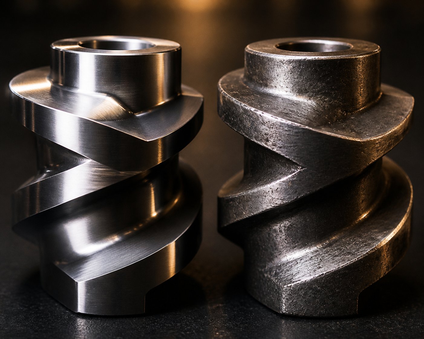
Screw Segment Materials and Wear Resistance
You can design the perfect screw configuration — flawless element sequencing, ideal kneading block stagger angles, perfectly tuned pitch ratios — and still watch throughput degrade within months. The culprit? The metal itself. Screw segment material selection is the invisible variable that determines whether your carefully optimized profile maintains its geometry under real-world processing conditions or slowly erodes into something unrecognizable.
Most discussions about screw elements focus on geometry and configuration. Material science rarely gets the same attention. Yet for processors running abrasive fillers, corrosive polymers, or high-volume production schedules, metallurgy is arguably the single most consequential purchasing decision after the screw profile itself.
Common Metallurgies for Screw Segments
Not every application demands the same level of wear protection. A screw segment manufacturer serving diverse industries typically offers a tiered material portfolio — each grade engineered for a specific balance of hardness, corrosion resistance, toughness, and cost. Understanding these tiers prevents both overspending on materials you don't need and underspending on materials that won't survive your process.
Here are the primary categories you'll encounter when specifying or sourcing elements:
Nitrided steel (e.g., 38CrMoAlA) is the general-purpose workhorse. The base steel is gas-nitrided to produce a hard surface layer — typically reaching 50-55 HRC — while maintaining a tough, ductile core. It handles standard polymer compounding at reasonable cost and performs well against moderate mechanical stress. However, nitrided steel offers limited protection against aggressive abrasive fillers or chemically corrosive environments. Think of it as the baseline: adequate for unfilled or lightly filled polymers, but not the right choice when glass fiber or mineral content climbs above 15-20%.
Through-hardened tool steels (e.g., D2, M2, H13) step up the performance significantly. These alloys are heat-treated throughout their cross-section rather than relying on a surface treatment alone. The result is deeper, more uniform hardness — and critically, the wear resistance doesn't disappear once a thin surface layer wears through. Tool steels are the standard recommendation for moderately abrasive compounds and applications where elements experience sustained high-pressure contact.
Powder metallurgy (PM) alloys, produced through hot isostatic pressing (HIP), represent the high-performance tier. These materials achieve extremely fine, uniform carbide distributions throughout the matrix — delivering superior wear resistance in heavily filled formulations where standard tool steels would erode unacceptably fast. PM alloys handle filler loadings of 40% glass fiber, high concentrations of calcium carbonate, and similarly demanding applications. The trade-off is cost: PM elements typically carry a significant premium over nitrided or tool steel equivalents.
Specialty alloys occupy the top of the material pyramid. Nickel-based alloys like Hastelloy resist the corrosive gases released during processing of halogenated polymers — PVC, PVDF, and fluoropolymers that would chemically attack conventional steels. Tungsten carbide coatings and carbide-rich alloys provide extreme abrasion resistance for applications like highly filled engineering plastics, mineral-loaded masterbatch, and recycled streams containing metallic contamination. These materials are reserved for the most punishing environments where no other metallurgy survives economically.
| Material Type | Hardness (HRC) | Corrosion Resistance | Abrasion Resistance | Relative Cost | Typical Application |
|---|---|---|---|---|---|
| Nitrided Steel (38CrMoAlA) | 50-55 | Fair | Moderate | Low | General polymer compounding, unfilled or lightly filled resins |
| Through-Hardened Tool Steel (D2, M2) | 55-62 | Fair to Good | High | Medium | Moderately abrasive compounds, standard filled systems |
| PM / HIP Alloys | 60-68 | Good | Very High | High | High filler loads (30-60% glass fiber, minerals), demanding compounding |
| Nickel-Based Alloys (Hastelloy) | 40-50 | Excellent | Moderate | Very High | Corrosive fluoropolymers, PVC, halogenated systems |
| Tungsten Carbide (Coated or Solid) | 70+ | Excellent | Extreme | Very High | Extreme abrasion: heavily mineral-filled, recycled streams with contamination |
The right choice depends on your specific material formulation and production volume. A processor running unfilled polypropylene for 2,000 hours per year will never justify tungsten carbide economics. A compounder pushing 40% glass-filled nylon on three shifts will never achieve acceptable element life with nitrided steel. Matching metallurgy to the application is where material science directly translates into operating cost.
Wear Patterns and Failure Modes
Screw segments don't fail suddenly in most cases. They degrade gradually — and the way they degrade tells you exactly what's happening inside your process. Recognizing wear patterns early is the difference between a planned element swap during a scheduled shutdown and an emergency teardown after product quality collapses.
Four primary degradation mechanisms attack screw elements segmented barrel assemblies, often simultaneously:
Abrasive wear is the most common culprit, responsible for roughly 50% of all wear cases in extrusion. Hard particles embedded in the polymer melt — glass fibers, calcium carbonate, talc, silica, recycled contaminants — act like sandpaper against metal surfaces. Every rotation grinds away microscopic amounts of material from flight tips, kneading disc edges, and the element's outer diameter. Rates of 0.05-0.15 mm per 1,000 operating hours are typical in abrasive applications, depending on filler type, loading level, and element metallurgy.
Adhesive wear accounts for approximately 30% of wear cases. Here, polymer melt bonds to the metal surface under heat and pressure, then tears away small metal particles when the bond breaks. Degraded polymer residue, thermal cycling, and zones of inadequate flow — where material stagnates and overheats — accelerate this mechanism. Adhesive wear is subtler than abrasive wear but equally destructive over time, particularly on elements processing sticky or thermally sensitive formulations.
Corrosive wear attacks from a chemical angle, representing about 15% of wear scenarios. Halogenated polymers like PVC release hydrochloric acid during processing. Flame retardants, certain stabilizer packages, and moisture-reactive additives generate corrosive byproducts that chemically dissolve the element surface. This type of degradation often appears as surface pitting, discoloration, or a rough, etched texture — fundamentally different from the smooth polishing effect of abrasive wear.
Fatigue cracking rounds out the failure modes, occurring in about 5% of cases. Cyclic loading — repeated pressure fluctuations, torque reversals during startup and shutdown, thermal expansion and contraction — creates micro-cracks that propagate over thousands of hours. Eventually, small surface fragments spall off, creating localized rough spots that accelerate all other wear mechanisms. Fatigue is the slowest but most insidious failure mode because the damage is often invisible until it reaches a critical threshold.
Regardless of the mechanism, wear manifests in three observable ways that directly harm processing performance:
- Tip diameter reduction — As the outer diameter shrinks, the clearance between the element and the barrel wall increases. This expanded gap allows material to leak backward over the flight tips instead of being conveyed forward, reducing effective throughput and weakening pressure buildup.
- Flight edge rounding — Sharp flight edges are essential for the self-wiping action that prevents material buildup and dead zones. Rounded edges allow polymer to accumulate in crevices, increasing residence time in uncontrolled spots and promoting thermal degradation.
- Surface pitting and roughness — Pitted surfaces create micro-dead zones where material stagnates, degrades, and contaminates the product stream. In kneading blocks, surface roughness alters the shear field and reduces mixing predictability.
The processing consequences compound each other. Increased leakage flow reduces throughput, which leads operators to increase screw speed to compensate, which raises melt temperature, which accelerates polymer degradation, which further increases adhesive wear. It's a vicious cycle that starts silently and escalates quickly once critical clearances are exceeded.
Inspection Criteria and Replacement Timing
How do you know when a screw segment has crossed the line from "acceptably worn" to "silently killing your process"? The answer lies in systematic measurement — not guesswork, not visual appearance alone, and certainly not waiting until product quality complaints pile up.
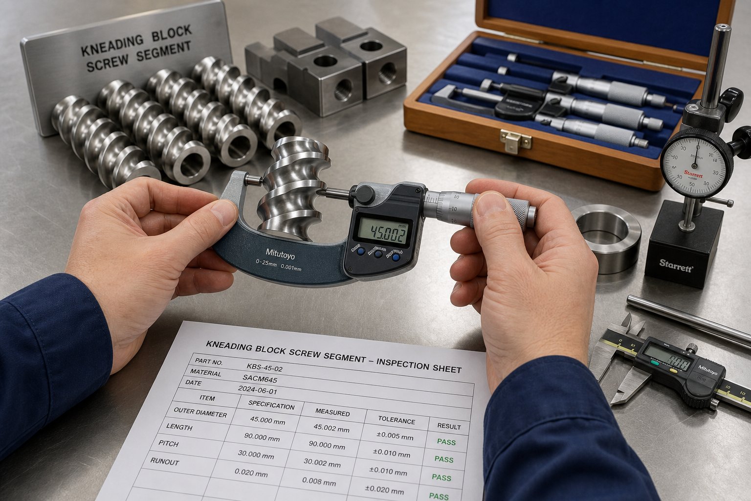
The most critical measurement is the element's outer diameter (OD). A micrometer check at multiple points along the element's length, compared against the original specification, tells you exactly how much material has been lost. Industry practice uses the concept of clearance increase percentage — how much the gap between flight tip and barrel wall has grown relative to the original designed clearance — as the primary replacement criterion.
While specific threshold values depend on your application, material, and quality tolerances, general industry benchmarks from wear analysis data suggest that a flight clearance exceeding approximately 0.15 mm typically warrants element replacement, and barrel inner diameter increases beyond 0.20 mm indicate the barrel itself may need relining. These numbers shift based on context — a pharmaceutical compounder running at tight tolerances may set replacement thresholds far more conservatively than a recycler processing post-consumer waste.
Beyond OD measurement, a practical inspection regimen from any screw segment factories or in-house maintenance team should include these tools and checkpoints:
- Precision outside micrometer (0.01 mm resolution) — Measure OD at the tip of each flight or kneading disc lobe, checking multiple points along the element length to detect uneven wear.
- Go/no-go gauges — Custom-ground gauges matching the maximum allowable OD reduction provide a fast pass/fail check during routine shutdowns without requiring detailed measurement logs.
- Visual inspection under good lighting — Look for scoring, pitting, discoloration, edge rounding, and spalling. These visual cues often identify the dominant wear mechanism before dimensional data confirms severity.
- Spline bore check — Worn or damaged spline bores cause elements to wobble on the shaft, creating uneven loading and accelerated barrel contact. Inspect bore fit with the shaft or a spline gauge.
- Surface roughness assessment — Run a fingernail or inspection probe across flight surfaces. Pitting you can feel indicates corrosive or fatigue-driven damage that may not be captured by OD measurement alone.
Timing matters as much as technique. Kneading blocks and reverse elements experience the highest shear forces and contact pressures in any configuration — they wear fastest and should be inspected most frequently. Conveying elements in the feed zone and vent zone, by contrast, operate under relatively mild conditions and typically last significantly longer. Building a wear history for each element position in your screw configuration allows you to predict replacement timing rather than react to failures after they've already degraded product quality.
Documenting wear rates also informs material selection decisions for future purchases. If a nitrided steel kneading block at position 6 consistently wears out in 3,000 hours while a PM alloy equivalent at the same position lasts 10,000 hours, the cost-per-hour calculation often favors the premium material — even at two or three times the upfront price. Without measurement data, that comparison remains invisible, and the cheaper element keeps getting reordered by default.
Material science determines how long your screw profile holds its designed geometry. But geometry and metallurgy together still only define the potential of a screw configuration — realizing that potential requires matching the right elements, in the right materials, to the specific demands of your application and industry.
Application-Specific Screw Segment Configurations
Geometry, nomenclature, and metallurgy give you the vocabulary. Applying that vocabulary to a real production challenge — a specific polymer, a specific filler, a specific end product — is where screw configuration either delivers or quietly destroys performance. The same kneading block that produces perfect pigment dispersion in a masterbatch line can cause catastrophic thermal degradation in a biopolymer process. Context is everything.
What follows is a breakdown of how compounding extruder segment screw layouts differ across the major processing categories. If you take away one principle from this section, let it be this: there is no universal screw profile. Every application demands its own element sequence.
Configurations for Polymer Compounding and Masterbatch
Compounding filled polymers — glass fiber reinforced nylon, mineral-loaded polypropylene, flame-retardant ABS — places some of the heaviest demands on screw segments for extruder performance. The core challenge is filler dispersion: breaking apart agglomerates and distributing particles uniformly throughout a viscous polymer matrix without degrading the base resin.
A typical compounding configuration starts with wide-pitch conveying elements in the feed zone to pull bulk material in quickly and maintain a starved feed condition. The melting zone follows, using a progression of decreasing-pitch elements to build fill level and initiate plasticization through frictional heating. Then comes the critical mixing zone — an aggressive sequence of kneading blocks, often starting at 45° or 60° stagger angles and escalating to 90° neutral blocks where maximum dispersive mixing occurs. As co-rotating twin screw configuration guides confirm, 90° kneading blocks deliver the strongest mixing capability with zero forward conveying, forcing 100% fill at that position — exactly the condition needed to shear apart tightly bonded filler clusters.
Downstream of the mixing zone, the configuration shifts abruptly. Wide-pitch conveying elements open up free volume for devolatilization, allowing moisture and volatiles to escape through barrel vent ports. A reverse element upstream of the vent creates a melt seal that prevents the vacuum from pulling material backward instead of pulling gases out.
Masterbatch production — particularly color concentrates — shifts the emphasis from dispersive to distributive mixing. Pigment particles are typically smaller and softer than mineral fillers, so the goal becomes even spatial distribution rather than brute-force breakup. Configurations for masterbatch tend to favor longer sequences of 30° forward kneading blocks and toothed mixing elements (ZME), which repeatedly split and recombine the melt stream to spread pigment uniformly. Over-shearing a color masterbatch causes pigment damage, color shift, and inconsistent letdown ratios — problems traced directly to overly aggressive kneading block selection in the mixing zone.
Screw Layout for Pelletizing and Recycling
Recycling applications face a unique dilemma: the polymer has already been through at least one heat-and-shear cycle. Its molecular weight is lower, its thermal stability is reduced, and it may carry moisture, residual inks, or trapped gases. Treating a recycled feedstock the same way you'd treat virgin resin — with aggressive melting and high-shear mixing — accelerates degradation and produces weak, discolored pellets.
Effective recycling screw designs prioritize gentle melting using gradual compression through progressively tighter-pitch conveying elements rather than abrupt kneading-block-driven melting. Multiple venting zones — sometimes two or three along the barrel length — handle the high volatile load. Each vent zone uses the same principle: a reverse element or neutral kneading block upstream to create a melt seal, followed by wide-pitch elements beneath the vent port to maximize melt surface area for gas extraction. Research published on twin screw extrusion as continuous mixing emphasizes that using multiple venting locations makes it possible to remove substantial quantities of volatiles — 30% or more — from the melt stream.
Pelletizing operations, whether processing virgin or recycled material, share a common downstream requirement: consistent, stable pressure at the die. Pressure fluctuations translate directly into uneven strand thickness, irregular pellet geometry, and die drool. Tight-pitch metering elements in the final barrel sections compress the melt and build uniform pressure before it exits through the strand die or pelletizer head. The core objective of pelletizing screw design is balancing high melting capacity against gentle processing — enough shear to fully plasticize the polymer, but not so much that it degrades before reaching the die face.
Specialized Setups for Reactive and Shear-Sensitive Processing
Reactive extrusion — where chemical reactions occur inside the barrel during processing — demands something most other applications actively avoid: extended residence time. Grafting reactions, crosslinking, and polymerization all require the melt to remain in specific temperature and shear conditions long enough for the chemistry to reach completion.
Achieving this means building deliberate flow restrictions into the screw profile. Reverse conveying elements and 90° neutral kneading blocks create fully filled, high-pressure zones where material accumulates and dwells. Stacking multiple restriction points in series extends total residence time from the typical 20-60 seconds up to several minutes, giving reactive components enough contact time to reach target conversion levels. The balance is delicate: too much restriction overheats the melt and drives side reactions; too little leaves the reaction incomplete.
Shear-sensitive materials — certain biopolymers, food-grade starches, pharmaceutical excipients, and thermally unstable elastomers — require the opposite philosophy. These formulations degrade rapidly under high mechanical energy input, so screw configurations emphasize gentle handling throughout. Wide kneading disc stagger angles (30° forward), generous free volume from deep-channel conveying elements, and the substitution of kneading blocks with toothed mixing elements wherever possible all reduce peak shear stress while still achieving adequate mixing.
In pharmaceutical applications, residence time distributions become particularly critical. As twin screw extrusion research has documented, the first-in, first-out nature of co-rotating TSEs produces a more uniform heat and shear history than batch processes — but only when the screw design properly manages fill level across the barrel length. A starved configuration with strategically placed mixing elements keeps residence time short and consistent, preventing localized overheating that could degrade active pharmaceutical ingredients.
Matching screw configuration to the specific application is the single most impactful decision in twin screw extrusion performance. No amount of barrel temperature adjustment or screw speed optimization can compensate for a fundamentally mismatched element sequence.
The cross-industry perspective here is clear: a china segment twin screw setup that excels in aggressive mineral compounding will fail spectacularly if transplanted unchanged into a food extrusion or reactive processing line. Each application category has its own logic, its own element preferences, and its own failure modes when those preferences are ignored. Suppliers specializing in modular screw elements — such as NANHAIYA — can provide application-specific configuration guidance for compounding, pelletizing, masterbatch, and recycling applications, drawing on hands-on experience with twin screw extruder users across these industries. That kind of application engineering support becomes especially valuable when you're entering a new process category or troubleshooting persistent quality issues on an existing line.
Speaking of troubleshooting — even a well-designed configuration eventually encounters problems on the production floor. Recognizing which symptoms point to screw-segment-related root causes, rather than chasing barrel temperatures or feed rates, is the fastest path back to stable operation.
Troubleshooting Common Screw Segment Problems
Your barrel temperatures look fine. Feed rates are stable. The drive isn't faulting. Yet the extrudate tells a different story — inconsistent color, surging output, or pellets that don't meet spec. The instinct is to chase temperature setpoints or blame the resin lot. But more often than you'd expect, the root cause sits inside the barrel, built into the screw configuration itself or hiding in the gradual dimensional decay of worn elements.
Diagnosing screw segment problems requires connecting visible symptoms to specific element-level causes. Here's how to read the signals your extruder is sending and trace them back to actionable fixes.
Poor Mixing Quality and Dispersion Issues
When filler agglomerates show up in the finished product — visible specks of undispersed carbon black, white streaks of unincorporated calcium carbonate, or blotchy color distribution — the mixing zone is the first place to look. As compounding expert Kenneth Russell explains in his treatment of twin screw mixing configuration, a material can be distributed but not dispersed, meaning particles are spread throughout the matrix but remain as large agglomerates that create uneven concentrations and non-uniform appearance.
Inadequate dispersion typically points to insufficient shear intensity in the kneading zone. The fix often involves swapping kneading blocks to higher stagger angles — moving from 45° forward blocks to 60° or 90° neutral configurations that force material to dwell longer under more intense elongational forces. Adding more kneading discs within the mixing section increases total shear exposure and helps break down stubborn particle clusters.
But there's an equally important failure mode running in the opposite direction: over-shearing. If you see yellowing, burning odor, loss of mechanical properties, or fiber length destruction in glass-reinforced compounds, the kneading zone is too aggressive. Russell notes that mixing sections work more efficiently and more gently at higher degrees of fill — and that kneading blocks in a low-fill section can actually "whip" the polymer, increasing melt temperature and damaging additive integrity rather than mixing productively.
The corrective path depends on which problem you're seeing:
- Undispersed agglomerates or color streaking — Add kneading blocks with higher stagger angles (60° or 90°), increase disc count, or cap the mixing section with a reverse element to raise fill level and shear efficiency.
- Thermal degradation or fiber breakage — Reduce kneading block aggressiveness by switching to lower stagger angles (30°), substitute toothed mixing elements (ZME) for some kneading blocks, or shorten the mixing zone length.
- Good dispersion but poor distribution — Increase distributive mixing by adding narrow-disc kneading blocks or toothed elements downstream of the dispersive zone. These elements split and recombine the melt stream without applying destructive shear forces.
Surging, Throughput Loss, and Pressure Instability
Output fluctuations — material coming out of the die in rhythmic surges, or throughput gradually declining over weeks — are among the most frustrating problems to diagnose because so many systems can contribute. Feed inconsistencies, temperature deviations, and screen pack loading all belong on the suspect list. But when those upstream factors check out clean, the screw elements themselves become the lead screw segment of the investigation.
Worn convey screw segment elements are the silent throughput killer. As a conveying element's outer diameter shrinks from abrasive wear, the clearance gap between flight tip and barrel wall widens. Material leaks backward over the flights instead of being pushed forward. You lose effective pumping action, and throughput drops even though screw speed stays constant. Twin screw extrusion troubleshooting data confirms that when the screw-to-barrel gap exceeds approximately 0.5 mm, wear is severe enough to compromise both shear plasticization and conveying efficiency, requiring element replacement.
Feed zone configuration is another common origin point. If the initial conveying elements don't have sufficient pitch to pull material in at the rate the feeder delivers it, the feed throat floods or the screw starves intermittently. Both conditions produce cyclic pressure swings downstream. OEM convey screw segment specifications typically provide guidelines for feed-zone pitch selection based on bulk density and target throughput — following those guidelines prevents most feed-related surging before it starts.
Pressure instability at the die end often traces to insufficient metering capability. Tight-pitch elements in the final barrel sections generate the stable, uniform pressure that the die demands. When these elements wear, or when the configuration simply doesn't include enough pressure-generating length, the result is erratic strand thickness, die drool, and variable pellet geometry. Reverse elements also play a critical role here: placed upstream of vent zones, they create melt seals that maintain fill level and prevent upstream pressure fluctuations from propagating downstream. A missing or incorrectly positioned reverse element can destabilize the entire pressure profile.
This table maps the most common symptoms to their likely screw-segment-related causes and recommended configuration changes:
| Symptom | Likely Segment-Related Cause | Recommended Segment Change |
|---|---|---|
| Output surging (cyclic) | Worn conveying elements in feed zone; insufficient melt seal upstream of vent; inadequate fill level in mixing zone | Replace worn conveying elements; add or reposition a reverse element or neutral kneading block to improve melt seal |
| Gradual throughput decline | Progressive OD wear on conveying and metering elements increasing leakage flow | Measure OD of all elements; replace any showing clearance increase beyond threshold; consider upgrading metallurgy at high-wear positions |
| High melt temperature | Overly aggressive kneading zone (too many 90° blocks or reverse elements); low fill level causing polymer whipping | Reduce kneading block count or stagger angle; add a mild restriction element to increase fill and reduce whipping |
| Poor degassing / bubbles | Insufficient free volume under vent port; missing or weak melt seal upstream of vent; vent-zone elements too short | Use wider-pitch conveying elements under the vent; ensure a reverse element or neutral block immediately upstream creates a complete seal |
| Material degradation / discoloration | Excessive residence time from too many restriction points; over-shearing in kneading zone | Remove one restriction element; shorten kneading block sequence; substitute ZME for aggressive kneading blocks |
A diagnostic principle worth remembering: pressure instability troubleshooting should always start by identifying where pressure changes and what pattern it follows — a slow trend, a repeating cycle, or random spikes each point to fundamentally different root causes. The screw configuration is only one system in the chain, but it's the one most often overlooked because it's buried inside the barrel and invisible during operation.
Excessive Wear and Premature Segment Failure
When elements wear out far faster than expected — kneading blocks lasting 2,000 hours instead of 8,000, conveying elements showing visible scoring after a single production campaign — the knee-jerk reaction is to blame material quality. Sometimes that's correct. But premature failure frequently traces back to a mismatch between the element's metallurgy and the process demands, or to a screw configuration that generates excessive localized pressure.
A logical diagnostic sequence for identifying the root cause of accelerated wear follows three steps:
- Check the material-to-metallurgy match. Is the element material rated for the abrasion and corrosion levels of your compound? Running nitrided steel against 40% glass-filled nylon is a predictable failure — the filler hardness overwhelms the surface treatment within hundreds of hours. Upgrading to PM or tool steel alloys at high-wear positions is often the most cost-effective fix when calculated on a per-hour basis.
- Examine the screw configuration for excessive pressure zones. Stacking multiple reverse elements and 90° kneading blocks in series creates extreme localized pressure and contact force. Elements in those positions experience wear rates several times higher than identical elements in gentler configurations. Sometimes reducing the restriction — switching one reverse element to a neutral kneading block, for instance — lowers wear dramatically without meaningfully affecting mixing quality.
- Evaluate process conditions against element capacity. High fill levels of abrasive materials amplify every wear mechanism. Running at maximum throughput with heavily filled compounds pushes even premium metallurgies to their limits. If wear rates remain unacceptable after material and configuration adjustments, the answer may be reducing fill percentage at that specific barrel position or distributing the mixing work across a longer sequence of gentler elements.
Recognizing these patterns — and fixing the underlying cause rather than just replacing the worn part — is what separates reactive maintenance from genuine process optimization. Yet even the best diagnostic instincts need support from disciplined installation practices and inspection routines that catch problems before they cascade into production failures.
Installation, Inspection, and Replacement Best Practices
Diagnosing a problem is only half the equation. The other half — the part that actually prevents the next failure — happens on the maintenance bench, at the end of the extruder barrel, and in the spare parts cabinet. A perfectly designed screw configuration assembled incorrectly can cause catastrophic barrel damage in minutes. A worn element left in service because nobody measured it last shutdown silently bleeds throughput for months. And a critical kneading block that's out of stock when you need it turns a two-hour element swap into a five-day production outage.
Surprisingly, end-to-end lifecycle management of screw segments — from the moment they slide onto the shaft to the day they're retired — rarely gets documented in one place. Here's the practical playbook.
Proper Installation and Assembly Techniques
Imagine you've just received a set of replacement elements — fresh kneading blocks, new conveying sections, maybe an upgraded OEM ZSK screw segment or a replacement sourced from a JSW screw segment factory. The temptation is to slide everything onto the shaft and get the line running. Resist that impulse. Assembly errors at this stage are among the most expensive mistakes in twin screw extrusion.
The correct procedure follows a deliberate sequence, and experienced extrusion engineers at Leistritz emphasize that every step matters:
- Clean the splined shafts thoroughly. Use a wire brush to remove any residual polymer, degraded material, or old anti-seize compound from the shaft splines. Contamination trapped between the shaft and element bore creates uneven seating, introduces wobble, and accelerates wear from the first revolution.
- Inspect every element before assembly. Check each piece for hairline cracks, nicks, gouges, and bore damage. Stone or sand element end faces flat using 320-grit sandpaper on a level surface — a marble slab or thick steel plate — working in a figure-eight pattern. Even microscopic irregularities on end faces create gaps between adjacent elements that allow polymer intrusion and thermal degradation.
- Apply anti-seize compound sparingly. Coat all shaft surfaces with a high-temperature anti-seize — products rated for extrusion temperatures that won't degrade or contaminate the melt stream. Wipe on, then wipe off. The goal is a thin film, not a thick layer. Any anti-seize that migrates onto element end faces during installation must be removed immediately; buildup between faces prevents proper element-to-element contact and can create processing dead spots.
- Position both shafts as a pair. If your shaft clamping fixture is available, use it to hold the shafts at the correct centerline distance and timing position. Without the fixture, clamp the shaft ends between two wood blocks at the proper spacing. Elements are always installed in pairs — one on each shaft — with each pair aligned face-to-face so the intermeshing profiles match.
- Follow the screw configuration drawing exactly. This sounds obvious, but it's where most errors occur. A single element installed backward — a forward conveying element placed in a reverse orientation, or a kneading block with the wrong stagger direction — will cause mechanical interference between the screws. Damaged elements can break apart while running, and as the Leistritz team warns, broken elements have been known to twist shafts, wreck barrels, and cause catastrophic gearbox failure.
- Verify intermesh clearance before inserting into the barrel. Lay the assembled screws on a flat surface, intermeshed correctly, and roll them back and forth while watching for interference. A consistent, visible gap should run between the two element sets. Use a flashlight to confirm — the line of light between the elements should remain constant. Any rubbing, clicking, or tendency for the screws to push apart indicates an incorrectly installed or misaligned element.
- Torque end caps to specification — but don't overtighten. Thread the screw tips on and tighten hand-tight during assembly. Final torquing happens after the screws are reinstalled in the extruder. Use the OEM-supplied tip wrench, tighten each tip until the gearbox starts to rotate, and stop. No cheater pipes, no impact wrenches on the tips. Co-rotating extruders typically use left-hand threads on the screw tips — double-check before you start turning.
After reinstallation, run the screws at very low speed — 1 to 2 rpm — for a few revolutions to confirm smooth operation. Then increase to approximately 20 rpm and listen. Minor clicking is normal on dry screws and usually disappears once material is introduced. Knocking sounds, however, signal an interference that requires immediate shutdown and inspection.
Routine Inspection and Maintenance Schedules
A screw configuration doesn't degrade overnight. Wear accumulates hour by hour, shift by shift, with each kilogram of abrasive compound grinding away microscopic amounts of metal. The processors who maintain consistent throughput over thousands of hours are the ones who inspect systematically — not the ones who wait until product quality forces a teardown.
Kneading blocks and reverse elements wear fastest because they operate under the highest contact pressures and shear forces. These positions should be your inspection priority at every planned shutdown. Conveying elements in the feed zone and vent sections experience comparatively mild conditions and can tolerate longer intervals between checks — but "longer" doesn't mean "never."
A practical inspection regimen built around scheduled shutdowns includes the following tools and checkpoints:
- Precision outside micrometer (0.01 mm resolution) — Measure the outer diameter of every high-wear element at multiple points along its length. Record values and compare against original specifications to calculate clearance increase.
- Go/no-go gauges — Custom or OEM-supplied gauges matching the maximum allowable OD reduction enable rapid pass/fail screening without detailed measurement at every position.
- Visual inspection under strong lighting — Look for scoring, pitting, discoloration, edge rounding, and surface spalling. These patterns reveal the dominant wear mechanism before dimensional data quantifies severity.
- Spline bore fit check — Verify that each element sits snugly on the shaft without radial play. Worn bores cause wobble, uneven barrel contact, and accelerated localized wear.
- End face flatness verification — Run end faces across a flat reference surface with 320-grit paper. Raised spots, grooves, or cupping indicate either manufacturing defects or in-service damage that compromises element-to-element sealing.
- Crack detection — Inspect cleaned elements for hairline cracks, especially around keyways and at the transition between flight tips and lobe roots. Cracked elements must be discarded immediately — they will fracture during operation.
The single most valuable habit you can build is record-keeping. Log measured OD values against operating hours for each element position after every inspection. Within two or three screw pulls, you'll have enough data to build position-specific wear curves that predict replacement timing weeks or months in advance. Predictive maintenance data from extrusion monitoring platforms confirms that after two or three replacement cycles with full dimensional records, processors can forecast element replacement timing within weeks — converting expensive emergency teardowns into planned maintenance events.
Cleaning should happen while elements are still hot whenever possible. Work on screws immediately after shutdown or reheat the shaft assembly in the extruder for about 20 minutes before disassembly. Use a steel-wire brush for initial cleaning, followed by an oven or fluidized bath for thorough polymer removal. For baked-on, degraded material that resists brass brushes, a belt sander, bench grinder with a steel-wire wheel, or dry-ice blaster will handle the job — just be cautious with element metallurgy temperature limits during thermal cleaning.
Optimizing Segment Inventory and Replacement Strategy
The most disciplined inspection program in the world can't help you if the replacement element you need is sitting in a ZSK screw segment factory overseas with a six-week lead time. Downtime cost per hour on a compounding line can run $1,000 to $5,000 or more depending on the product. Multiply that by days — not hours — waiting for parts, and the cost of carrying spare inventory looks like a bargain.
The key is stocking strategically, not broadly. Your wear data tells you which positions consume elements fastest. Those positions — typically the primary mixing zone kneading blocks, reverse elements, and the first few conveying elements downstream of any side feeder introducing abrasive filler — should have dedicated spares on hand at all times. Elements in low-wear positions, like vent-zone conveying sections, can be ordered on a replenishment cycle rather than stocked in depth.
A practical inventory strategy breaks down into three tiers:
| Priority Tier | Element Positions | Inventory Recommendation |
|---|---|---|
| Critical (stock immediately) | Primary mixing zone kneading blocks (all stagger angles in use), reverse elements, screw tips | Minimum one complete set of each, ready to install |
| High (stock at least one spare) | Feed zone conveying elements, metering zone tight-pitch elements, elements downstream of side feeders | At least one spare of each type; order replacements as soon as a spare is consumed |
| Standard (order on schedule) | Vent zone conveying elements, transition sections, low-wear positions | Order during planned procurement cycles based on projected wear rates |
There's also a strategic question about individual element replacement vs. full screw refresh. Replacing only the worn elements is the most cost-efficient approach when wear is concentrated in predictable positions and the rest of the assembly retains good dimensional integrity. But if your wear data shows that a majority of elements across the full configuration are approaching replacement thresholds simultaneously — which happens naturally as an assembly ages — refreshing the entire screw set at once makes more sense. A full refresh ensures uniform clearances and consistent processing behavior along the entire barrel length, eliminating the risk that a few borderline elements create weak spots in an otherwise renewed configuration.
The decision framework is straightforward: if fewer than 25-30% of elements need replacement, swap individually. If more than half the elements are marginal, consider a complete rebuild. In between, use your wear curves and production schedule to time a full refresh during a planned shutdown rather than replacing elements piecemeal across multiple unplanned stops.
Building reliable supplier relationships matters here too. A supplier who understands your specific extruder platform, maintains consistent dimensional quality across production batches, and can deliver critical spares on short notice is worth far more than the lowest line-item price on a one-time purchase order. That relationship — and how to evaluate potential suppliers — is where the final piece of the lifecycle puzzle falls into place.
How to Choose a Reliable Screw Segment Supplier
Your wear data is dialed in, your inspection regimen is running like clockwork, and your spare inventory tiers are mapped to every position on the shaft. All of that discipline falls apart the moment you order replacement elements from the wrong source. A kneading block that's 0.05 mm oversize on the bore. A conveying element machined from an inferior alloy that wears out in half the expected hours. A shipment that arrives six weeks late because the supplier outsources grinding to a third party with no capacity commitment. The screw segment supplier you choose determines whether your maintenance program actually protects throughput — or just looks good on paper.
Critical Evaluation Criteria for Screw Segment Suppliers
Not every company listing replacement elements in a catalog has the manufacturing depth to deliver parts that perform like the originals. Evaluating screw segment suppliers requires looking past pricing headlines and digging into the engineering and quality infrastructure behind the product. Here's a practical checklist — treat any missing item as a question that needs answering before you place a purchase order:
- Material certifications and metallurgical traceability — Demand EN 10204 3.1 certificates for every batch. These documents trace the raw material from its origin through heat treatment and final inspection. A supplier who can't produce them on request either isn't tracking their metallurgy or is sourcing from uncontrolled channels.
- Dimensional tolerances and quality control documentation — Request tolerance specifications for outer diameter, bore, flight depth, and element length. Reputable suppliers provide dimensional inspection reports as standard deliverables, not as special requests. Tight OD tolerances — typically within 0.01-0.02 mm of nominal — are non-negotiable for maintaining the screw-to-barrel clearances that drive mixing efficiency.
- OEM compatibility verification — If you're replacing elements on a ZSK, TEX, or Leistritz platform, the supplier must demonstrate exact spline compatibility, correct intermeshing geometry, and matching element length increments. Ask for cross-reference documentation showing their part numbers mapped against original OEM designations.
- Range of element types and sizes offered — A segment twin screw supplier with a comprehensive catalog — covering conveying elements, kneading blocks in all standard stagger angles, toothed mixing elements, reverse configurations, and screw tips across multiple shaft diameters — signals genuine manufacturing capability rather than cherry-picked product lines.
- Responsiveness to custom or application-specific requests — Can the supplier modify a standard element's pitch, disc count, or metallurgy to match your specific process needs? Custom capability separates manufacturers with in-house engineering from resellers who can only ship what's already on the shelf.
- Surface finish quality — Flight surfaces and kneading disc faces should arrive polished to specifications that minimize polymer adhesion and drag. Rough or inconsistent finishes increase energy consumption and accelerate adhesive wear from day one.
Use this checklist systematically. Score each potential supplier against every criterion before comparing prices. A screw segment factory that checks every box at a moderate price point will deliver far lower lifecycle cost than one offering rock-bottom pricing with gaps in traceability or tolerance control. As industrial component sourcing experts emphasize, quality, reliability, and technical capability should pass the evaluation gate before cost comparisons even begin.
OEM vs. Aftermarket Segment Sourcing
Every processor faces this decision eventually: reorder through the original extruder manufacturer's parts department, or source from an aftermarket specialist? Both paths have legitimate value — the key is understanding where each one earns its premium or delivers its savings.
Pros of OEM Sourcing
- Guaranteed dimensional and metallurgical compatibility with your specific machine
- Full manufacturer warranty on replacement parts
- Single-source accountability — no finger-pointing if a part doesn't perform
Cons of OEM Sourcing
- Premium pricing that includes brand margin and distribution overhead — often 2x to 3x aftermarket equivalents
- Longer lead times, especially when parts ship from centralized facilities overseas
- Limited metallurgy options beyond the OEM's standard portfolio
Aftermarket screw segment suppliers like NANHAIYA can offer equivalent-quality modular screw segments, kneading blocks, and screw elements compatible with major extruder platforms — often with faster lead times and competitive pricing for twin screw extruder users in compounding, pelletizing, masterbatch, and recycling applications. The critical factor, regardless of source, is verifying dimensional accuracy, material grade, and surface finish through the same documentation standards you'd demand from any tier-one supplier.
Experienced procurement teams often adopt a hybrid approach. They source capital equipment and complex proprietary components through the OEM, then build parallel relationships with qualified aftermarket manufacturers for consumable wear parts. That dual-channel strategy captures OEM engineering depth where it matters most while reducing lifecycle costs on the elements that need periodic replacement. Requesting a screw segment pricelist from both your OEM parts department and two or three aftermarket suppliers gives you the data to quantify the actual cost difference for your specific element set — and the leverage to negotiate better terms from either side.
When evaluating a china screw segment source specifically, apply the same rigor you would to any supplier: verify factory capabilities through audits or third-party inspection reports, request and check customer references processing similar materials, and confirm that quality documentation meets international standards. The best Chinese manufacturers have invested heavily in CNC precision grinding, advanced metallurgy, and ISO-certified quality systems — but the gap between top-tier and lower-tier producers remains wide, making due diligence essential.
Bulk Purchasing and Long-Term Partnership Value
A one-time purchase order tells you whether a supplier can deliver parts. A long-term relationship tells you whether they can deliver consistency — and that distinction matters enormously when you're depending on replacement elements to maintain process stability across years of production.
Establishing a wholesale screw segment relationship or a screw segment bulkbuy agreement with a qualified supplier unlocks advantages that single-order purchasing simply cannot match:
- Batch-to-batch consistency — When a supplier knows your specifications, metallurgy preferences, and tolerance requirements from repeated orders, the risk of receiving out-of-spec parts drops dramatically. They calibrate their processes to your standards, not generic catalog specs.
- Priority lead times — Long-term customers typically receive preferential scheduling. When an urgent replacement need arises, you're not competing with first-time buyers for production capacity.
- Application engineering support — A supplier who understands your process history can proactively recommend metallurgy upgrades, suggest configuration adjustments based on your wear patterns, and help optimize element selection for new formulations. That level of support transforms a parts vendor into a technical resource.
- Cost advantages — Volume commitments often unlock tiered pricing structures that reduce per-element cost meaningfully — savings that compound across dozens of replacement cycles over a machine's service life.
The right supplier relationship extends beyond parts supply to become a technical partnership — one where your wear data, application challenges, and production goals inform every element they manufacture for you.
Building that partnership starts with a simple step: share your screw configuration drawings, your wear history data, and your material specifications with potential suppliers early in the evaluation process. The ones who respond with thoughtful questions about your application — rather than just a quote — are the ones worth investing in for the long term. A genuine segment twin screw supplier partner doesn't just ship metal. They help you keep your throughput where it belongs.
Frequently Asked Questions About Screw Segments
1. What is a screw segment and how does it work in a twin screw extruder?
A screw segment is an individual, modular element that slides onto a splined shaft to build a complete screw profile inside a twin screw extruder. Each segment performs a targeted function — conveying, melting, mixing, venting, or pressure generation — at a specific barrel position. Because they lock together via a keyway or spline connection, processors can rearrange, swap, or replace any single element without disassembling or discarding the entire screw. This modularity allows one extruder to handle dozens of different polymers and formulations simply by reconfiguring the element sequence on the shaft.
2. How do I choose the right screw segment material for abrasive or corrosive compounds?
Material selection depends on your compound's filler type, loading level, and chemical properties. For general-purpose unfilled or lightly filled polymers, nitrided steel (such as 38CrMoAlA) offers adequate wear resistance at low cost. Moderately abrasive formulations benefit from through-hardened tool steels like D2 or M2, which maintain hardness deeper into the cross-section. High filler loads — above 30% glass fiber or mineral content — typically demand powder metallurgy (PM/HIP) alloys for acceptable element life. Corrosive environments involving PVC, fluoropolymers, or halogenated compounds require nickel-based alloys like Hastelloy. Suppliers such as NANHAIYA (nhyscrew.com) offer tiered metallurgy options matched to specific application demands across compounding, recycling, and masterbatch processing.
3. What do screw segment part numbers like 'SE 30/30 R' or 'KBW 45/5/30' mean?
Screw segment nomenclature encodes geometry and function in a compact format. For conveying elements, a designation like 'SE 30/30 R' means: SE = screw element, 30 = pitch in mm, 30 = length in mm, and R = right-handed (forward conveying). For kneading blocks, 'KBW 45/5/30 R' translates to: KBW = full-width kneading block, 45 = stagger angle in degrees, 5 = number of discs, 30 = total length in mm, and R = forward rotation. While naming conventions vary slightly between extruder brands like ZSK, JSW, and Leistritz, the underlying logic of pitch, length, stagger angle, and rotation direction remains consistent across the industry.
4. How often should screw segments be inspected and when should they be replaced?
High-wear positions — kneading blocks, reverse elements, and elements downstream of abrasive filler side feeders — should be inspected at every planned shutdown using a precision micrometer to measure outer diameter loss. General industry practice recommends replacement when flight clearance exceeds approximately 0.15 mm beyond the original specification, though exact thresholds depend on the application and quality tolerances. Building a wear history log for each element position over two or three screw pulls enables predictive maintenance, allowing you to forecast replacement timing weeks in advance rather than reacting to product quality failures after they occur.
5. Should I buy OEM screw segments or source from aftermarket suppliers?
Both options are viable when quality is verified. OEM segments guarantee dimensional and metallurgical compatibility with your machine but typically carry 2x to 3x price premiums and longer lead times. Qualified aftermarket manufacturers can deliver equivalent-quality elements compatible with major platforms like ZSK, TEX, and Leistritz — often faster and at lower cost. The critical step is verifying dimensional tolerances, material certifications (EN 10204 3.1), spline compatibility, and surface finish quality regardless of the source. Many processors adopt a hybrid strategy: OEM parts for complex proprietary components and aftermarket suppliers for consumable wear elements, maximizing both quality assurance and cost efficiency.
Written by
Nanhaiya Technical Team
Zhoushan Nanhaiya Plastic Machinery Co., Ltd.
The Nanhaiya technical team supports screw and barrel manufacturing projects through application review, technical communication, custom manufacturing coordination, and production and quality control.
Discuss Your Application
Related Articles
More insights on screw barrel technology and plastics processing.
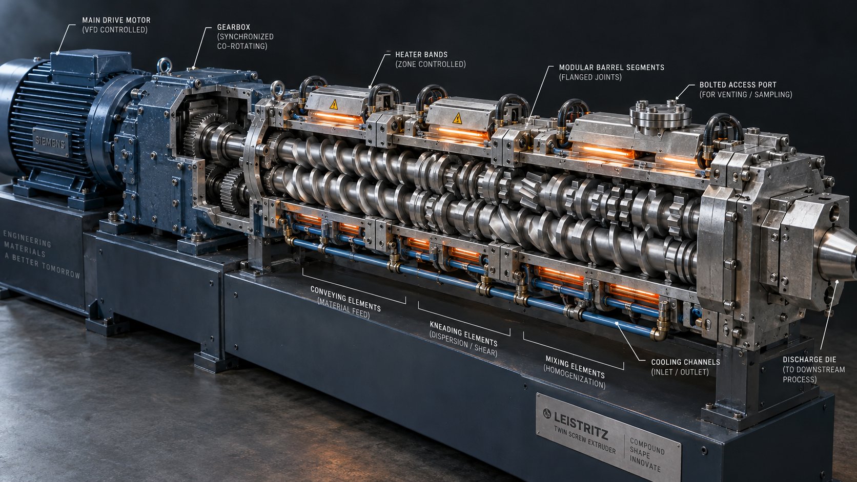
Co Rotating Twin Screw Extruder Parts: From Drive To Die Face
Oct 12, 2026
Complete guide to co rotating twin screw extruder parts — screw elements, kneading blocks, barrel segments, drive components, and material grades explained for sourcing and optimization.
Read Article
What Nobody Tells You About Screw Barrel For Plastic Machine Design
Oct 10, 2026
Learn how screw barrel for plastic machine design affects melt quality, throughput, and wear life. Covers geometry, resin matching, troubleshooting, and sourcing.
Read Article
Single Screw Extruder for Sheet: Stop Guessing, Start Specifying
Oct 9, 2026
Learn how to specify a single screw extruder for sheet production. Covers screw geometry, resin-specific processing, troubleshooting, and maintenance best practices.
Read ArticleLooking for something else?
Search by material, symptom or product and jump straight to the relevant page.
These are navigation suggestions based on keyword matching — not a quotation, not a delivery commitment, and not a substitute for engineering review. Final specification is confirmed by our engineers against your drawings and processed material.
Need help with screw barrel selection?
Share your machine model, processed material and application. Our team can help with pricing and technical support.