

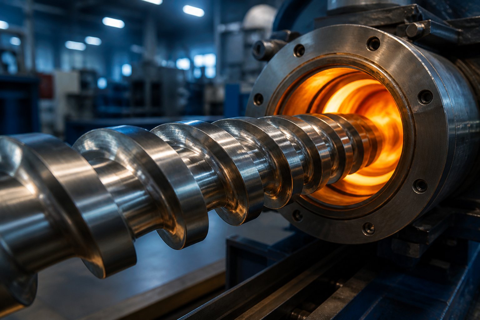
What a Screw Plastic Extruder Actually Does
Defining the Screw Plastic Extruder
Ever wonder how raw plastic pellets become the pipes, films, and profiles you encounter every day? The answer lies in one remarkably efficient machine.
A screw plastic extruder is a machine that uses one or more rotating Archimedean screws inside a heated barrel to melt, mix, and continuously push thermoplastic material through a shaped die, producing products with a consistent cross-sectional profile.
That single sentence captures the core of how a plastic extrusion screw works, yet the engineering behind it is anything but simple. The rotating screw does not just transport pellets from one end to the other. It generates frictional and viscous shear heat within the polymer itself, builds the pressure needed to force a thick melt through a narrow die opening, and homogenizes the material so every millimeter of the final product shares the same properties.
Why the Screw Is the Most Critical Component
Imagine the extruder barrel as a stage. Heaters, sensors, and the drive motor all play supporting roles, but the screw is the lead performer. Its geometry dictates how quickly pellets melt, how uniformly additives disperse, and how much output the line delivers per hour. In fact, barrel heaters typically contribute only 10-20% of the total energy that melts the polymer. The remaining 80-90% comes from mechanical shear generated by the screw's rotation. Change the screw design, and you fundamentally change the process outcome. That single component controls shear rate, residence time, pressure buildup, and melt temperature all at once.
What This Resource Covers
This guide consolidates everything you need to evaluate, operate, or replace a screw extruder into one place. You'll move through a clear decision journey:
- Process fundamentals — how the three functional zones convert solid pellets into a uniform melt.
- Screw geometry variables — flight depth, pitch, compression ratio, and mixing elements that shape melt quality.
- Machine configurations — single-screw, twin-screw, and multi-screw options compared side by side.
- Technical specifications — L/D ratio, torque, speed, and throughput data engineers need during evaluation.
- Applications and troubleshooting — matching screw design to pipe, film, sheet, or compounding lines and diagnosing common problems by symptom.
Whether you are selecting a new extruder, optimizing an existing line, or deciding if a worn screw warrants replacement, every section ahead builds toward a more confident, data-driven decision. The journey starts where the pellets start: at the feed zone of the screw.
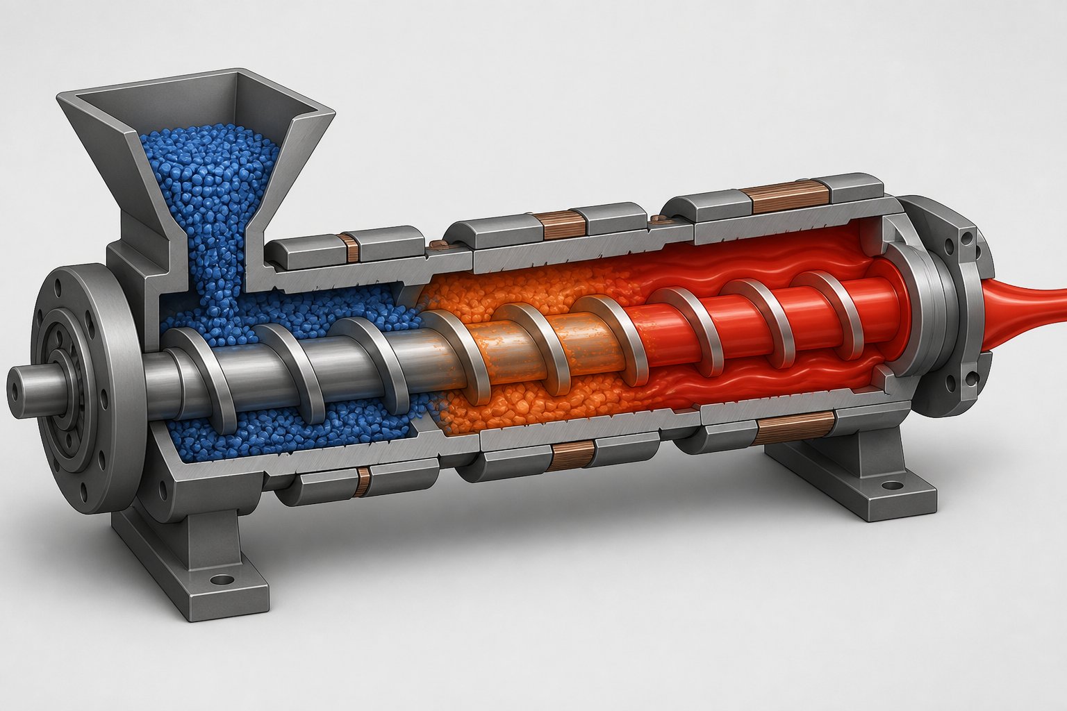
How the Three Functional Zones Drive the Extrusion Process
A handful of plastic pellets enter one end of the barrel. Seconds later, a uniform, pressurized melt exits the other. What happens in between is governed by three distinct zones along the screw, each with a specialized job. Understanding how plastic melts inside an extruder barrel starts with understanding this zone-by-zone progression.
Feed Zone and Solids Conveying
The feed zone is where it all begins. Pellets drop from the hopper into the deep channels of the screw, and the rotating flights push them forward along the barrel. Channel depth here is deliberately deep — the screw needs maximum volume to accept a steady supply of loose, low-bulk-density granules.
Two forces compete in this zone: the pellets must stick to the barrel wall (so they get dragged forward by the flight angle) and slide freely on the screw root (so they don't just spin in place). Barrel heating plays a real role here, but only a supporting one. Its job is to raise the surface temperature enough for the polymer to grip the barrel. As extrusion specialists note, barrel heating is initially required before startup to create that surface adhesion, but once rotation begins, mechanical shear takes over as the dominant energy source.
Some high-output lines use grooved feed barrels — barrels with axial or helical grooves cut into a separately water-cooled feed section. These grooves dramatically improve the intake of slippery, hard-to-convey polymers like HDPE. The tradeoff? A grooved feed throat typically demands a shallower feed zone and a deeper metering zone, sometimes with little or no compression at all, plus additional downstream mixing hardware to compensate for reduced homogenization.
Compression Zone and Melt Initiation
Picture the walls closing in. That is essentially what happens in the compression (or transition) zone: the flight depth gradually decreases, squeezing the material into a smaller and smaller cross-section. This compaction does two critical things simultaneously.
- Expels trapped air. Air pockets between pellets get pushed back toward the feed throat, preventing voids in the final melt.
- Initiates melting through shear. As the channel narrows, the polymer is pressed harder against the hot barrel wall, and the thin melt film that forms gets continuously wiped away by the advancing flight. This exposes fresh solid material to the barrel surface, accelerating the melting cycle.
The compression ratio of an extrusion screw is defined as the ratio of the feed-zone channel depth to the metering-zone channel depth. According to veteran extrusion engineer Allan Griff, this ratio typically falls between 2:1 and 4:1. A higher ratio means more aggressive compaction — useful for semi-crystalline polymers that undergo a sharp solid-to-liquid transition. A lower ratio suits shear-sensitive or amorphous materials that soften gradually and risk degradation under excessive mechanical work. Keep in mind, though, that compression ratio alone cannot fully describe a screw design unless at least one actual channel depth is also specified.
Metering Zone and Melt Delivery
By the time material reaches the metering zone, it should be fully molten. This final section features a constant, shallow channel depth, and its purpose shifts from melting to pumping and homogenizing. The shallow channel generates high shear rates that blend any remaining temperature gradients, ensuring every stream of melt reaches the die at a consistent viscosity and pressure.
Here is where the balance between shear heat and barrel heaters becomes especially visible. In most steady-state operations, the drive motor's rotational energy — converted to thermal energy via viscous shear — supplies the vast majority of heat entering the polymer. Barrel heaters often function more as fine-tuning instruments, compensating for heat losses or making minor temperature adjustments rather than acting as the primary energy source. In some processes, barrel zones in the metering section actually run with cooling enabled, extracting excess shear heat to prevent degradation.
The table below provides a quick-reference summary of the extruder screw feed, compression, and metering zones:
| Zone Name | Primary Function | Typical Flight Depth Trend | Key Design Variable |
|---|---|---|---|
| Feed Zone | Accept and convey solid pellets forward; establish barrel-wall adhesion | Constant and deep | Channel depth (must accommodate bulk density of incoming material) |
| Compression (Transition) Zone | Compact solids, expel air, and initiate melting via shear and conduction | Gradually decreasing | Compression ratio (feed depth ÷ metering depth, typically 2:1 to 4:1) |
| Metering Zone | Homogenize the melt and pump it at constant pressure toward the die | Constant and shallow | Channel depth and length (control shear rate, residence time, and output pressure) |
How Twin-Screw Zone Concepts Differ
Single-screw extruders rely on these three fixed zones machined into one continuous piece of steel. Twin-screw extruders take a fundamentally different approach. Instead of a monolithic screw, they use modular screw elements — individual segments that slide onto a splined shaft and can be rearranged like building blocks.
As detailed in NC State Extension's screw profile research, the three primary element categories are:
- Conveying elements — deep-flighted segments that transport material forward without imparting significant shear, functioning similarly to the feed zone of a single screw.
- Kneading elements — staggered disk blocks that perform distributive and dispersive mixing. Forward-angled kneading blocks are less aggressive; neutral blocks increase residence time and energy input; reverse-angled blocks push material backward, generating maximum shear and restriction.
- Reverse (re-conveying) elements — left-handed segments that create localized back pressure, ensuring thorough mixing or enabling venting upstream.
This modularity means an engineer can reconfigure the same twin-screw extruder for vastly different tasks — from gentle blending to aggressive reactive extrusion — simply by rearranging or swapping elements on the shaft. No gold standard screw profile exists for all materials, because every polymer exhibits unique flow behavior under varying temperature and shear conditions.
The interplay between these zones — or elements — ultimately determines melt quality. Yet the zones themselves are shaped by a set of precise geometric variables: flight depth, pitch, helix angle, and compression ratio. Each of these dimensions deserves a closer look, because changing even one can shift the entire process outcome.
Screw Geometry Variables That Control Melt Quality and Throughput
A screw plastic extruder may look like a single piece of machined steel, but its performance is encoded in a handful of geometric dimensions. Adjust one variable — say, flight depth — and you simultaneously change shear rate, melt temperature, residence time, and output. Every dimension interacts with every other, which is why screw design is often described as a blend of art and science. The table below maps the most influential variables to their process effects before we unpack each one individually.
| Design Variable | What It Controls | High-Value Effect | Low-Value Effect |
|---|---|---|---|
| Flight Depth | Shear rate, residence time, and volumetric capacity | Deeper channels increase throughput capacity but reduce shear intensity and melt uniformity | Shallow channels raise shear rate and improve melting but limit volumetric output |
| Pitch / Helix Angle | Conveying efficiency, pressure generation, and shear input | Longer pitch (higher helix angle) increases forward conveyance and shear input per revolution | Shorter pitch raises pressure-building capability but reduces conveying speed and throughput |
| Number of Flights | Mixing intensity and channel volume | Multi-flight designs improve mixing and melt uniformity; reduce individual channel cross-section | Single-flight screws maximize channel volume and simplify manufacture; mixing relies on other elements |
| Compression Ratio | Compaction aggressiveness and melting rate | Ratios of 3:1 to 4:1 suit semi-crystalline polymers needing aggressive compaction (HDPE, PP, nylon) | Ratios of 1.5:1 to 2.5:1 protect shear-sensitive amorphous resins (PVC, PMMA, PC) from degradation |
| Mixing Section Type | Dispersive vs. distributive melt homogenization | Dispersive elements (Maddock) break down unmelted particles; high shear and pressure drop | Distributive elements (pineapple, pin) redistribute melt layers with minimal temperature rise |
Flight Depth and Its Impact on Shear and Output
Think of flight depth as the distance from the top of the flight to the screw root — essentially, the height of the channel the polymer occupies. When you reduce that depth, the polymer gets compressed into a thinner layer between the screw root and the barrel wall. The velocity gradient across that thinner layer steepens, and shear rate climbs.
Here is the tradeoff you'll face every time: shallow flights generate more shear heat and improve melting efficiency, but they also reduce the volume of material the channel can carry per revolution. Deep flights do the opposite — they boost volumetric throughput while sacrificing shear intensity and melt uniformity. The relationship between extruder screw flight depth and shear rate is essentially inverse, and the optimal balance depends on the polymer's sensitivity to heat and the line's output target.
As a practical example, a screw designed for processing LLDPE blown film typically uses a relatively shallow metering depth to ensure the melt is perfectly homogenized for thin-gauge uniformity. A screw for a large-diameter pipe line, on the other hand, may use deeper metering flights to maximize kg/hr output, relying on mixing elements downstream to compensate for reduced shear homogenization.
Pitch, Helix Angle, and Conveying Efficiency
Pitch is the axial distance between two consecutive flights. On most general-purpose screws, pitch equals the screw diameter — a configuration called "square pitch" with a helix angle of approximately 17.66 degrees. But pitch is not locked to that standard. Understanding how screw pitch affects plastic extrusion output helps you see why some screws deviate from it.
Increasing the pitch lengthens each helical wrap, which means the flight covers more axial distance per revolution. The result is faster forward conveyance and greater shear input into the polymer. NC State Extension research confirms that increasing pitch increases shear input, while decreasing either channel depth or width amplifies that effect further. Conversely, a tighter pitch shortens the helical path, slows conveyance, and raises the screw's ability to build pressure — useful in metering zones or where back-pressure resistance from the die is high.
The number of flights adds another dimension. A single-flight screw — the most common configuration — provides one continuous helical channel and maximizes the cross-sectional area available for material flow. Multi-flight screws (double or even triple flights) subdivide that channel into narrower parallel paths. Each narrower path sees a higher shear rate and more frequent melt reorientation, improving mixing. The penalty is reduced channel volume per flight and, consequently, lower throughput capacity unless screw speed is increased to compensate.
Compression Ratio for Amorphous vs Semi-Crystalline Polymers
Compression ratio deserves special attention because it is one of the first parameters engineers specify — and one of the most commonly misunderstood. As a quick reminder, it is the ratio of feed-zone channel depth to metering-zone channel depth. A ratio of 3:1 means the metering channel is one-third the depth of the feed channel.
Why does this matter so much for polymer selection? Semi-crystalline polymers like HDPE, polypropylene, and nylon undergo a relatively sharp solid-to-liquid phase change. They need aggressive compaction to ensure that every crystallite melts before reaching the metering zone. A compression ratio for semi-crystalline polymers typically falls in the 3:1 to 4:1 range, sometimes higher, to deliver the mechanical energy required for that abrupt transition.
Amorphous polymers — think polycarbonate, PMMA, or rigid PVC — soften gradually over a wide temperature range. They do not need (and often cannot tolerate) the same level of compactive energy. Excessive compression generates too much shear heat, risking thermal degradation, discoloration, or molecular-weight breakdown. For these materials, ratios in the 1.5:1 to 2.5:1 range are typical.
One important caveat: compression ratio alone does not fully describe the screw's melting behavior. Two screws with identical 3:1 ratios can perform very differently if their feed-zone depths, transition-zone lengths, or screw diameters differ. Always pair the ratio with at least one absolute channel depth measurement and the transition-zone length for a meaningful comparison.
Barrier Screws and Specialized Mixing Elements
Standard screws rely on the three-zone concept to melt and convey polymer, but they have an inherent limitation: solid pellets and molten polymer share the same channel. As the melt film grows along the barrel wall, solid particles can break free from the solid bed and contaminate the melt stream, creating gels or unmelted particles in the final product.
Barrier screws solve this by introducing a secondary flight — the barrier flight — with a slightly smaller diameter than the main flight. This creates two distinct sub-channels: one for solids and one for melt. As melting progresses, the melt channel widens while the solids channel narrows, and polymer can only cross from the solids side to the melt side by passing over the barrier flight in a thin, fully molten film. The result is dramatically improved melt quality and a more predictable melting process. The difference between a barrier screw vs. a standard screw for extrusion is most visible in crystalline polymer applications, where the solid-bed breakup problem is most severe.
Extrusion veteran Jim Frankland notes that barrier screws effectively eliminated the need for supplemental high-shear mixers that were originally developed for conventional screw designs. Once material passes through a properly designed barrier section, it should be completely melted. Adding a dispersive mixer after the barrier section often needlessly raises melt temperature and reduces output through added pressure drop.
That said, mixing elements still play an important role — the key is choosing the right type:
- Maddock (dispersive) mixing sections — Also known as UCC or Leroy-style mixers, a Maddock mixing section on an extruder screw forces the melt through a narrow clearance gap, applying intense shear. This is valuable on standard (non-barrier) screws where unmelted particles may still exist. On barrier screws, however, Frankland argues they are rarely the best choice because the barrier section has already completed melting, and additional shear simply overheats the polymer.
- Distributive mixers (pin, Saxton, pineapple) — These work by repeatedly dividing and recombining the melt stream rather than applying intense shear. Pin mixers create exponential melt divisions based on the number of pins and rows, effectively overcoming the limitations of laminar flow. Pineapple mixers converge those divisions at varying angles for chaotic mixing, making them particularly effective for color dispersion. Saxton mixers use interrupted flights to redirect flow between channels, primarily aiding thermal homogenization with minimal pressure drop.
The practical takeaway? Match your mixing element to what the melt actually needs. If the screw already includes a barrier section, a distributive mixer is usually the better complement — it homogenizes temperatures and disperses colors or additives without the penalty of excessive melt-temperature rise and reduced output. Reserve dispersive elements for situations where particle size reduction or aggressive melting is specifically required.
Screw geometry, in the end, is never one-size-fits-all. The optimal combination of flight depth, pitch, compression ratio, and mixing section depends on the polymer you're processing, the product form you're targeting, and the throughput your line demands. Even small geometry changes cascade through the entire process, which is exactly why choosing the right machine configuration — single-screw, twin-screw, or multi-screw — matters just as much as the screw profile itself.
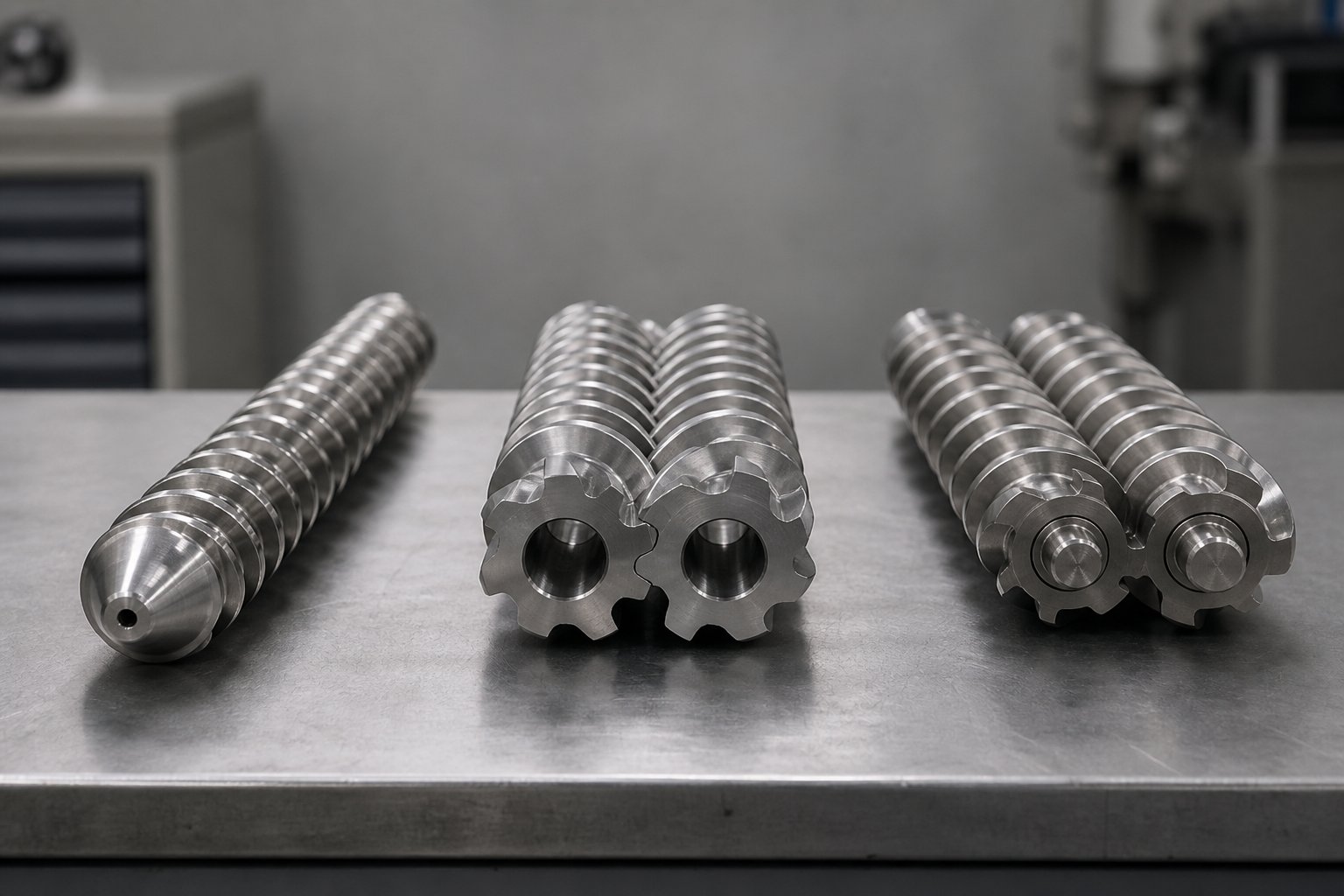
Single-Screw vs Twin-Screw vs Multi-Screw Extruder Comparison
Screw geometry defines what happens to the polymer — but the number of screws and the way they interact with each other determines the machine's fundamental capabilities. A perfectly optimized single-flight barrier screw cannot give you the intensive compounding performance of a twin-screw design, and a high-shear co-rotating twin is the wrong tool for gentle PVC profile extrusion. Choosing the right configuration is a strategic decision that locks in your capital cost, your processing flexibility, and your material options for years.
Single-Screw Extruder Strengths and Limitations
The single-screw extruder remains the workhorse of the plastics industry, and for good reason. Its design is mechanically straightforward — one screw, one barrel, one drive — which translates into lower acquisition cost, simpler maintenance, and proven reliability in steady-state operations. When your line runs a single polymer formulation day after day, producing pipe, profile, film, or sheet, a well-designed single-screw machine delivers consistent output with minimal operator intervention.
Where does it fall short? Mixing. A single screw relies on drag flow along the barrel wall to convey and melt material, and its distributive mixing capability is inherently limited. As USEON's comparison guide points out, the single-screw design is best described as a plasticating and conveying machine rather than a compounding one. Adding barrier flights and mixing sections helps, but the machine still cannot match a twin-screw extruder's ability to handle multi-component blends, high filler loadings, or reactive chemistries. You'll also notice that throughput and screw speed are tightly coupled on a single screw — you cannot independently adjust one without affecting the other.
Co-Rotating Twin-Screw Extruder Advantages
If you need to blend, compound, devolatilize, or react, the co-rotating twin-screw extruder is almost certainly the platform you want. Its two screws rotate in the same direction inside a figure-eight barrel bore, and the fully intermeshing geometry creates a powerful self-wiping action. Material is forcibly handed from one screw flight to the next at the intermeshing zone, leaving virtually no dead spots where polymer can stagnate and degrade.
Why does self-wiping matter so much? Two reasons. First, it keeps the residence time distribution narrow, which is critical during reactive extrusion and when processing thermally sensitive formulations. Second, it dramatically speeds up material changeovers — there is simply less old compound clinging to metal surfaces when you switch colors or formulations.
The modular screw architecture amplifies this flexibility further. Conveying elements, kneading blocks, and reverse-flight segments can be arranged along the shaft in nearly infinite combinations, allowing the engineer to dial in precisely the right balance of shear, residence time, and pressure for each application. A co-rotating twin screw extruder for compounding handles everything from glass-fiber-reinforced nylon to carbon-nanotube nanocomposites, polymer alloys, color masterbatch, and biodegradable blends. The tradeoff is cost: twin-screw machines carry higher capital expense, greater spare-parts complexity, and demand more specialized operator knowledge than their single-screw counterparts.
Counter-Rotating and Multi-Screw Configurations
Counter-rotating twin-screw extruders occupy a distinct niche. Here, the two screws turn in opposite directions, drawing material into the intermeshing zone under compression rather than the high-shear handoff of co-rotating designs. The result is stable conveying at low rotational speed with minimal shear heating — exactly what thermally fragile materials need.
Rigid PVC is the textbook example. Its decomposition temperature sits dangerously close to its processing temperature, and the high-shear kneading zones of a co-rotating machine can push it over the edge. A counter-rotating extruder for PVC pipe extrusion holds melt temperature close to the barrel setpoint by operating at high fill and low speed, while a gentle calendering effect at the intermeshing region disperses stabilizers and lubricants without overworking the polymer. This is why counter-rotating machines dominate PVC pipe, sheet, and profile production worldwide.
Beyond twin-screw territory, planetary roller extruders represent another specialized option. These machines use satellite rollers orbiting a central sun spindle inside a helically grooved barrel, creating a thin melt film — typically 0.1 to 1 mm thick — that is continuously folded and renewed. Because heating is conduction-dominated rather than shear-driven, melt temperature tracks the barrel setpoint closely. Planetary roller machines excel at high-filler compounds (up to 80% CaCO3 by weight in PE masterbatch) and heat-sensitive PVC formulations, though they are not suited for reactive extrusion requiring precise residence time control.
Choosing the Right Configuration for Your Application
The single screw vs twin screw extruder differences come down to a fundamental trade: simplicity and cost versus mixing intensity and flexibility. The table below consolidates the key decision factors so you can match each configuration to your specific material, application, and budget constraints.
| Configuration | Pros | Cons | Best-Fit Materials | Relative Cost | Typical Applications |
|---|---|---|---|---|---|
| Single-Screw | Simple design; low maintenance; cost-effective; proven reliability for steady-state runs | Limited mixing and compounding capability; throughput tied to screw speed; poor for multi-component blends | PE, PP, PS, PET, PVC (with appropriate screw design) | Lowest | Pipe, profile, blown and cast film, flat sheet, wire coating |
| Co-Rotating Twin-Screw | Superior dispersive and distributive mixing; self-wiping; modular screw design; independent speed/throughput control | Higher capital and maintenance cost; complex screw configuration requires expertise; wear accelerated with abrasive fillers | Filled compounds, polymer alloys, reactive systems, masterbatch, engineering plastics | High | Compounding, reactive extrusion, devolatilization, masterbatch, recycling |
| Counter-Rotating Twin-Screw | Low shear; positive conveying; excellent for heat-sensitive polymers; stable at low RPM and high fill | Lower mixing intensity than co-rotating; limited use outside PVC and similar formulations | Rigid and plasticized PVC, WPC formulations | Medium-High | PVC pipe, PVC profile, PVC sheet, wood-plastic composites |
| Planetary Roller Extruder | Conduction-dominated heating; very low shear; handles ultra-high filler loadings (up to 80%); self-cleaning geometry | Niche applicability; requires discharge screw for die pressure; not suited for reactive extrusion; limited global supplier base | Rigid PVC, high-CaCO3 PE masterbatch, WPC, heat-sensitive elastomers | High | PVC calendering feed, high-filler masterbatch, WPC compounding |
Knowing when to use a twin screw plastic extruder versus a single-screw machine is really about asking the right sequence of questions: How many components are in your formulation? Does the polymer tolerate high shear? Do you need to switch materials frequently? Is mixing performance or raw throughput your primary bottleneck? The answers steer you toward the right column in the table above — and once the machine configuration is locked, the next critical step is understanding how to read and compare the technical specifications that separate one extruder from another within that category.
How to Evaluate Screw Extruder Specifications That Actually Matter
Spec sheets for a screw plastic extruder can run several pages long, listing everything from motor frame size to barrel zone count. But engineers and procurement teams who know how to evaluate screw extruder specifications zero in on a handful of interrelated numbers that reveal how a machine will actually perform with their polymer and product. Here are the ones worth your attention.
L/D Ratio and Its Influence on Residence Time
The extruder screw L/D ratio — screw length divided by its diameter — is arguably the first number anyone checks, and for good reason. It determines how much barrel length is available for melting, mixing, and building pressure.
- What it means: A 90 mm screw with an active length of 2,700 mm has an L/D ratio of 30:1. Common ratios for single-screw machines range from 24:1 to 36:1, while twin-screw extruders stretch from 20:1 to 48:1 depending on the application.
- Why it matters: A longer screw provides more residence time for thorough melting and mixing, which is essential for devolatilization, reactive extrusion, or processing highly filled compounds. Shorter ratios (20:1 to 28:1) keep residence time brief — ideal for thermally sensitive materials like color masterbatch or rigid PVC, where extended heat exposure causes degradation.
- What to watch for: Longer screws increase capital cost, require more floor space, and extend changeover time because there is simply more barrel to purge. A higher L/D ratio at moderate screw speed often achieves better melt quality than a short screw driven at high speed, because aggressive speed compensations introduce excess shear heat and risk polymer degradation. As a practical guideline from gearbox engineering data, increasing L/D from 24:1 to 30:1 also raises torque demand by roughly 10-20%, a factor your drive system must accommodate.
Screw Speed, Torque, and Drive System Considerations
Screw speed and torque are two sides of the same coin — connected through the motor and gearbox, yet serving very different roles in the process.
- Screw speed (RPM): Higher speed increases throughput and shear rate, but also raises melt temperature. Each polymer has a maximum safe peripheral (circumferential) speed beyond which degradation becomes unavoidable. For example, polycarbonate typically caps around 0.3 m/s, while polyethylene tolerates speeds above 0.8 m/s. Calculating peripheral speed — screw diameter multiplied by pi multiplied by RPM, divided by 60 — is a quick sanity check that prevents you from overdriving a sensitive resin.
- Torque rating: This is where many buyers get tripped up. A 75 kW motor sounds impressive, but the actual turning force delivered to the screw depends entirely on the gearbox ratio and its efficiency. The core formula is straightforward: Output Torque (Nm) = Motor Power (kW) x 9,550 / Output Speed (RPM) x Gearbox Efficiency. Two machines with identical motor power but different gear ratios will deliver very different torque values at the screw. When comparing a screw extruder torque rating vs motor power, always request the rated continuous output torque at the gearbox shaft — not the peak or overload rating, which is only sustainable for seconds.
- Torque per unit volume (specific torque): Particularly relevant for twin-screw machines, this metric divides the output torque per shaft by the cube of the screw diameter (in cm). A higher specific torque value indicates more processing capability per unit of screw volume — a far more meaningful comparison across machine sizes than raw motor kW. Modern high-performance co-rotating gearboxes deliver 10 to 18+ Nm/cm³, while standard units typically land between 5 and 12 Nm/cm³.
Barrel Pressure and Throughput Capacity
Barrel pressure and throughput close the specification loop by connecting screw output to the die and downstream equipment.
- Barrel pressure rating: The maximum pressure the barrel and head assembly can safely withstand, typically measured in bar or psi. Standard extrusion barrels are rated for 350 to 700 bar, but applications with highly restrictive die geometries — complex PVC profiles, fine medical tubing, or multi-layer blown film dies — can push melt pressure toward the upper end of that range. Always verify that the barrel pressure rating exceeds your expected operating pressure by a comfortable margin, and confirm that the pressure transducer and rupture disk are rated accordingly.
- Throughput capacity by screw diameter: Output scales with screw size, but the relationship is not linear. Extrusion engineering guidelines show that throughput grows roughly with the square to the cube of the diameter ratio, depending on screw design, polymer, and speed. A 60 mm single-screw extruder processing HDPE might deliver 80 to 200 kg/hr, while a 90 mm machine on the same material could reach 250 to 600 kg/hr — far more than a simple 1.5x diameter increase would suggest. Crucially, throughput data from manufacturers is always material-specific and cannot be transferred across polymers without recalculating for viscosity, peripheral speed limits, and drive power availability.
- How these specs interact: No specification exists in isolation. Imagine you want better melt homogeneity on a 30:1 L/D screw. You could increase speed — but that raises shear heat and torque demand simultaneously. Alternatively, you could extend the screw to 36:1 at the same moderate speed, gaining mixing length without the thermal penalty. That choice, however, increases torque demand by 10-20%, meaning your gearbox and motor must have the headroom to handle it. Evaluating specs means evaluating their interactions, not reading numbers in isolation.
These specifications tell you what a machine can do on paper. The real proof comes from matching those numbers to a specific application — pipe, film, sheet, compounding, or recycling — where screw design, die geometry, and downstream equipment all converge into a working production line.
Applications Across Pipe, Film, Sheet, and Pelletizing Lines
Specifications on a data sheet only become meaningful when they meet a real production line. A screw extruder for pipe extrusion faces entirely different demands than one producing 20-micron blown film or compounding 40% glass-fiber nylon. Each product category imposes its own requirements on screw geometry, barrel configuration, and downstream equipment — and understanding those requirements is what separates a well-matched line from one that fights you every shift.
Ranked by global production volume, the major application categories break down as follows:
- Pipe and tubing — the single largest end-use segment for extruded plastics by tonnage
- Film (blown and cast) — driven by packaging demand worldwide
- Sheet and thermoforming stock — food packaging, signage, and automotive interior panels
- Profile extrusion — window frames, decking, weatherstripping, and custom cross-sections
- Pelletizing and compounding — the upstream step that feeds every other category
Pipe and Profile Extrusion Screw Requirements
Pipe extrusion is where the single-screw extruder dominates. The process demands steady-state output at high volume with consistent melt pressure — exactly what a well-designed single screw delivers hour after hour. Yet the screw design varies significantly depending on the polymer.
A screw extruder for pipe extrusion running HDPE typically uses a compression ratio in the 3:1 to 3.5:1 range to handle the polymer's sharp crystalline melting point. Barrier screw designs are common because they prevent solid-bed breakup from contaminating the melt stream — a defect that shows up as stress-whitening or weak spots in the pipe wall. L/D ratios of 30:1 or longer ensure complete plasticization at production speeds, and grooved feed barrels are frequently paired with HDPE pipe screws to maximize solids conveying for this slippery, high-crystallinity resin.
PVC pipe, by contrast, lives in a different thermal universe. Its decomposition temperature hovers dangerously close to its processing temperature, so the screw must deliver gentle, controlled melting. Counter-rotating twin-screw extruders handle rigid PVC pipe production almost exclusively, operating at low speed with high barrel fill to keep shear heating minimal. Compression ratios stay low — often around 2:1 — and screw flight surfaces require corrosion-resistant metallurgy because PVC releases hydrochloric acid as it degrades.
Profile extrusion — window frames, decking boards, weatherstripping — shares many screw design principles with pipe but adds a layer of complexity. Profiles feature irregular cross-sections with varying wall thicknesses, and the die's flow resistance changes across the profile geometry. This means the screw must deliver exceptionally stable melt pressure; even minor output surging creates dimensional variation that makes the profile unusable. Single-screw machines with barrier flights and distributive mixing sections are the standard here, often running at moderate speeds to prioritize pressure stability over raw throughput. Downstream, vacuum sizing tanks and precision calibrators hold the still-soft profile to exact dimensional tolerances as it cools.
Film and Sheet Line Screw Design Choices
If pipe extrusion rewards consistency, film extrusion demands perfection. A 25-micron blown film acts as a magnifying glass for every flaw in the melt — a single unmelted particle becomes a visible gel or fish-eye that can ruin an entire roll. That is why barrier screw design for blown film extrusion is not a nice-to-have; it is close to essential.
Barrier screws separate the solid and melt channels with a secondary flight, ensuring that only fully molten polymer reaches the metering zone. For polyethylene film lines — especially LLDPE, which has higher viscosity and torque demand than LDPE — a barrier screw paired with a Maddock or distributive mixing section delivers the melt homogeneity thin gauges require. Film screw engineering data shows that L/D ratios of 30:1 to 33:1 are standard for blown film, with the practical minimum sitting around 24:1. Drop below that, and you sacrifice the barrel length needed for complete melting and thorough mixing.
Cast film and flat sheet lines follow a similar logic but use slot dies and chill rolls instead of air rings and bubble towers. Sheet screws can sometimes tolerate slightly less aggressive mixing than blown film screws because sheet gauges are thicker and more forgiving of minor melt inconsistencies. Thermoforming sheet for food packaging, however, still requires excellent melt uniformity to avoid weak spots that cause blowouts during the forming step.
Across both film and sheet, the screw's job is clear: melt completely, mix thoroughly, and deliver a thermally uniform output. Anything less shows up as a visible defect in the final product.
Pelletizing, Compounding, and Recycling Applications
Pelletizing and compounding lines flip the script. Instead of pushing a melt through a shaping die, these systems focus on mixing multiple ingredients — base resin, fillers, reinforcements, stabilizers, pigments — into a homogeneous compound, then cutting it into uniform pellets for downstream processors to use.
This is where the twin screw extruder for plastic compounding takes over. Co-rotating twin-screw machines provide the intensive dispersive and distributive mixing that high-filler formulations demand. Their modular screw architecture lets engineers place kneading blocks exactly where aggressive mixing is needed and conveying elements where gentle transport is required. Glass-fiber-reinforced nylon, carbon-black masterbatch, flame-retardant ABS, and polymer alloys all run on co-rotating twin-screw platforms because no single-screw design can match their blending intensity.
Recycling operations layer additional challenges on top of standard compounding demands. As recycled-feedstock processing guides detail, recycled plastics introduce three problems that virgin resin does not:
- Contamination — sand, glass fragments, metal fines, paper residue, and traces of incompatible polymers act as abrasive grinding paste against screw flights and barrel bore, accelerating wear dramatically.
- Inconsistent feedstock — flake and regrind have irregular particle shapes and variable bulk density, causing feeding instability and output surging that pellets never produce.
- Reduced thermal stability — every prior heat cycle consumes part of the polymer's stabilizer package, leaving a narrower safe processing window before degradation sets in.
Effective screw design for plastic recycling extrusion addresses all three: wear-resistant bimetallic barrels and hardened flight surfaces handle the abrasion, deeper feed sections and sometimes grooved feed zones or crammer feeders stabilize the intake of irregular flake, and vented two-stage screw designs remove trapped moisture and volatiles that would otherwise cause bubbles and surface defects. Melt filtration via continuous screen changers is also essential on recycled lines, and the screw's metering section must generate enough pressure to push melt through fine filter screens without sacrificing throughput.
Because each of these application categories demands a different combination of screw geometry, barrel metallurgy, and mixing capability, sourcing becomes a practical challenge for operations teams managing multiple line types. Suppliers like NANHAIYA address this by offering custom screw and barrel configurations tailored to specific line types — pipe, profile, film, sheet, and pelletizing — making it easier to match screw geometry to the exact requirements of each application rather than settling for a compromise design.
Matching the screw to the application, however, is only half the equation. The extruder's output must also align precisely with everything that comes after it — the die, the cooling system, the puller, and the cutter. A mismatch between screw output and downstream capacity is one of the most overlooked sources of defects and downtime in extrusion operations.
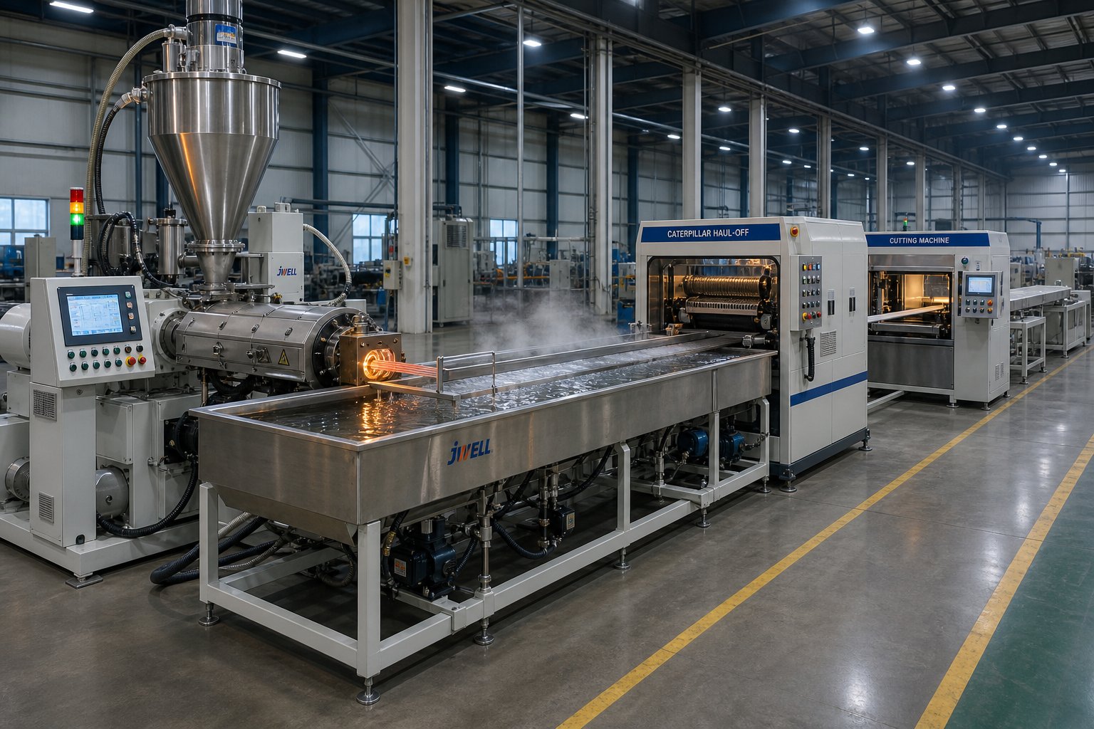
Downstream Equipment for a Plastic Extrusion Line: Matching Every Component to Screw Output
A perfectly designed screw means nothing if the equipment waiting at the die exit cannot keep up — or runs too fast. Imagine a kitchen where the chef plates food flawlessly, but the wait staff delivers it cold, stacked sideways, and cut to the wrong size. The screw and barrel produce the melt; everything downstream determines whether that melt becomes a sellable product or scrap. Defects like wall thickness variation, surface marks, warped profiles, and dimensional drift frequently trace back not to the extruder itself but to a mismatch between screw output and the downstream equipment that shapes, cools, sizes, pulls, and cuts the extrudate.
The table below gives you a systems-level checklist. Use it to verify that every downstream component is matched to the extruder's output characteristics before chasing screw-side adjustments.
| Downstream Component | Function | Critical Matching Parameter | Consequence of Mismatch |
|---|---|---|---|
| Die | Shapes the melt into the desired cross-section (pipe, film, sheet, profile) | Die pressure drop must align with the screw's metering-zone output pressure and flow rate | Excessive die pressure causes motor overload and melt overheating; insufficient pressure leads to surging, uneven flow distribution, and poor surface finish |
| Cooling System | Removes heat to solidify the extrudate and lock in final dimensions | Cooling capacity and uniformity must match the polymer's crystallization rate and the extruder's mass throughput (kg/hr) | Under-cooling produces soft, deformable product; over-cooling causes stress cracking or warping; uneven cooling creates ovality in pipes and bow in profiles |
| Calibration / Sizing Tooling | Holds the still-soft extrudate to precise dimensional tolerances during initial cooling | Sizing sleeve or calibrator bore must match the target OD, and vacuum level must suit the polymer's stiffness at forming temperature | Incorrect vacuum sizing causes OD drift, surface drag marks, or collapsed sections; misalignment produces uneven wall distribution |
| Haul-Off / Puller | Draws the extrudate through cooling and sizing at a controlled, constant speed | Puller speed must synchronize with the extruder's volumetric output to maintain target wall thickness and dimensional stability | Too fast thins the product and stretches it beyond tolerance; too slow causes bunching, sagging, or wall thickening; speed oscillation produces periodic dimensional variation |
| Cutter / Winder | Separates the continuous extrudate into finished lengths or rolls | Cutting or winding speed must track line speed precisely; blade or saw type must suit the product geometry and material | Mistimed cuts produce inconsistent lengths; dull blades create burrs or deformation at cut ends; winder tension mismatches cause stretching or telescoping on rolls |
Die Design and Its Relationship to Screw Output
The die is where the melt stream takes its final shape, and how to match die design to screw extruder output is one of the most consequential engineering decisions on any extrusion line. Two key die parameters interact directly with screw performance: geometry (the flow channel shape) and land length (the parallel section at the die exit where the melt stabilizes before emerging).
A die with a restrictive flow channel — say, a complex multi-cavity profile die or a fine-gauge film die with a narrow gap — generates significant back-pressure. The screw's metering zone must be capable of overcoming that pressure while still delivering sufficient flow rate. If the die restriction exceeds what the screw can push through at its rated speed, you'll see motor amperage climb, melt temperature spike from excess shear, and throughput drop. Conversely, a die with low restriction paired with a high-pressure screw creates an unstable flow front, leading to surging and poor surface quality.
Land length plays a subtler role. Longer lands increase the die's pressure drop but also give the melt more time to develop a uniform velocity profile across the die opening. Shorter lands reduce pressure requirements and allow higher throughput, yet they risk uneven flow — particularly at the edges of flat sheet dies or the thinner sections of a profile die. The right land length depends on the polymer's viscoelastic behavior: high-viscosity HDPE tolerates shorter lands than low-viscosity PP, which needs the extra residence time in the land to equalize flow.
Cooling, Calibration, and Sizing Equipment
Once the melt exits the die, a race begins. The polymer must be cooled uniformly and quickly enough to lock in the dimensions that the die and sizing tooling establish — but not so aggressively that thermal stresses warp the product or crystallization gradients create weak spots.
Cooling systems vary by product geometry:
- Water baths and spray tanks — standard for pipe and profile. The extrudate passes through a series of water-filled or spray-cooled tanks, with temperature and flow rate controlling the cooling gradient. For pipe extrusion, water temperatures typically run between 15 and 25 degrees Celsius, and the total cooling length can stretch 6 to 12 meters depending on pipe diameter and wall thickness.
- Air rings — used in blown film production. Ambient or chilled air is directed uniformly around the bubble's circumference to cool and stabilize the film as it expands. Air ring design directly affects frost line height, bubble stability, and film thickness uniformity.
- Chill rolls — used for cast film and flat sheet. The melt contacts a temperature-controlled chrome roll immediately after the die, and rapid conductive cooling freezes the sheet surface. Roll temperature, speed, and contact angle all influence crystallinity and optical clarity.
Vacuum sizing for pipe and profile extrusion deserves special attention because it is where dimensional control truly happens. The hot, still-soft extrudate enters a calibration sleeve — a precisely bored metal tube — and vacuum draws the pipe or profile outward against the sleeve's inner surface. As pipe extrusion specialists note, sizing support stability is often the single most important factor in holding OD and roundness on spec. If vacuum level fluctuates even slightly, the pipe sees a different forming force over time, producing gradual OD drift or roundness changes that are difficult to correct with a single adjustment. Sealing surfaces, vacuum pump consistency, and water spray coverage inside the calibrator all need to remain steady for repeatable results.
Haul-Off, Cutting, and Winding Systems
The haul-off unit — sometimes called the puller — sets the line speed and, by extension, controls draw ratio. Extrusion line haul-off speed synchronization with the extruder's output rate is what keeps wall thickness stable on pipe, maintains gauge uniformity on film, and prevents profile distortion.
Consider the physics: the screw pumps a fixed volume of melt per revolution at a given back-pressure. If the puller runs faster than the natural extrusion rate, it stretches the still-pliable extrudate, thinning the walls. If it runs slower, material accumulates and the product thickens or sags between the die and the cooling station. Modern haul-off units use servo-driven belts or caterpillar tracks with closed-loop speed control that holds line speed within fractions of a percent, but even small perturbations — belt slippage from worn pads, inconsistent grip pressure, or mechanical vibration — introduce periodic dimensional variation that mirrors the haul-off's irregularity.
Downstream of the puller, cutting and winding equipment must also track line speed precisely. Planetary saws and flying cutters for rigid pipe and profile synchronize their travel speed with the line during the cut, then retract and reset before the next length arrives. Mistimed cuts produce short or long pieces, and dull blades deform the product at the cut face. For flexible tubing and film, winders must apply consistent tension without stretching the product. Too much tension on a still-warm tube can change its diameter; too little creates loose, unstable rolls that are difficult to ship and unwind.
The overarching principle is straightforward: every piece of downstream equipment must be tuned to the extruder's output — not the other way around. When a quality problem appears, resist the reflex to adjust the screw speed first. Check the downstream chain systematically, starting at sizing conditions, then cooling, then haul-off speed, because the root cause often lives far from the barrel. That same diagnostic mindset — tracing symptoms back to root causes — becomes even more valuable when the defects themselves are the starting point, which is exactly where a structured troubleshooting approach pays off.
Troubleshooting Common Screw Extruder Problems by Symptom
Something is wrong on the line. Output is cycling, parts show dark contamination, or throughput has quietly dropped 15% below where it ran six months ago. The instinct is to start adjusting — bump screw speed, raise barrel temps, increase back pressure. But reactive tweaking without diagnosis usually trades one problem for another. A far more effective approach is to start with what you can actually observe — the symptom — and work backward toward root causes.
The table below organizes the most common screw extruder issues into a quick-reference diagnostic format. Use it as your first response before changing any setpoints.
| Symptom | Possible Causes | Corrective Actions |
|---|---|---|
| Surging or uneven output | Inconsistent solids conveying (feed casing or screw too hot); worn metering-zone flights increasing clearance; incorrect barrel temperature profile; feed throat bridging; inconsistent pellet or regrind bulk density | Check feed casing temperature (should be warm, not hot); verify screw cooling water flow; measure screw flight OD and barrel bore for wear; review temperature setpoints in Zone 1; inspect hopper for bridging or ratholing |
| Poor melt homogeneity or gels | Insufficient mixing capability in screw design; solid-bed breakup on a standard (non-barrier) screw; degraded barrier flight allowing unmelted particles past; wrong screw geometry for the polymer | Evaluate whether a barrier screw or mixing section is warranted; inspect barrier flight for wear that allows solids to bypass; reduce screw speed slightly to extend residence time; confirm compression ratio suits the polymer type |
| Black specks or degradation | Dead spots in the screw channel, adapter, or die where material stagnates and carbonizes; excessive residence time during low-speed holds or shutdowns; poor purging after material changeover; barrel temperatures set above polymer's safe window | Classify the contamination pattern — random, repeating, or batch-related — before intervening; inspect die lip and adapter for buildup; review purge procedure and changeover protocol; check whether specks track a specific regrind lot or persist across all material |
| Excessive screw or barrel wear | Abrasive fillers (glass fiber, mineral, CaCO3) accelerating erosion; screw-to-barrel misalignment causing metal-to-metal contact; incompatible metallurgy between flight hardfacing and barrel liner; foreign objects entering through the hopper | Measure screw flight OD and barrel bore ID at regular intervals; verify machine alignment; specify wear-resistant bimetallic barrel liners and compatible flight hardfacing alloys for the application; install magnets and screens upstream of the feed throat |
| Low throughput relative to specification | Worn metering-zone flights allowing excessive back-leakage over the flight land; high die back-pressure from clogged screen pack or restrictive die geometry; feed throat bridging or starve feeding; screw design undersized for target output | Compare current screw flight OD against original spec — clearance should be approximately 0.001 in. per side per inch of diameter when new; replace screen pack and check die for partial blockage; confirm feed system delivers consistent volumetric supply; evaluate whether screw diameter or speed increase is needed |
Surging, Uneven Output, and Feed Inconsistencies
Surging — the oscillatory rise and fall of extruder output while all setpoints remain constant — is one of the most disruptive problems a line can experience. It causes dimensional variation, increased scrap, and often triggers a cascade of operator adjustments that make diagnosis harder. According to extrusion specialist Mark A. Spalding of Dow, the most common root cause for screw extruder surging output is improper temperatures in the solids conveying section. Hot feed casings and hot screws top the list.
Here is why temperature matters so much in the feed zone. Successful solids conveying depends on the polymer gripping the barrel wall (forwarding force) while sliding freely on the screw root (minimized retarding force). Both forces are directly proportional to the stress at the metal-polymer interface, which is a strong function of surface temperature. If the feed casing gets too hot — because cooling water channels have occluded with mineral scale, for example — the pellets start to melt prematurely on the barrel wall, and the frictional grip that drives conveyance collapses. The same problem occurs when the screw itself overheats due to inadequate internal cooling. In one documented case on an 8-inch two-stage extruder running polystyrene, surging was traced to an internal screw cooling hole that was three diameters too short, failing to reach the end of the solids conveying section. Extending the cooling bore and adding a water pump eliminated the surging permanently.
A practical first check? Touch the feed casing. It should feel warm, not hot. Next, if screw cooling is installed, disconnect the return hose into a bucket and observe whether water is actually flowing — and whether it comes out excessively hot. These five-minute inspections often pinpoint the issue before any disassembly is needed.
Melt Quality Issues and Degradation Symptoms
Black specks, gels, and discolored streaks are among the most misdiagnosed defects in extrusion because the same visual symptom can originate from completely different sources. Diagnostic frameworks for black specks in plastic extrusion troubleshooting emphasize reading the contamination pattern before taking any corrective action:
- Random specks — more consistent with external contamination: foreign particles in raw material, regrind, or the conveying system.
- Repeating or periodic specks — point toward die buildup releasing in cycles, dead-spot accumulation inside the flow path, or progressive degradation from extended heat exposure.
- Batch-related specks — appear only with a specific material lot or after a specific changeover, indicating raw material contamination or incomplete purging.
The critical diagnostic fork is separating internal generation from external introduction. If specks persist even after switching to clean virgin resin, the source is almost certainly inside the machine — carbonized material trapped in dead spots within the screw channel, adapter, or die. If specks disappear when you change material batches, look outside the extruder first: inspect hopper contents, regrind quality, conveying lines, and screen pack condition.
Dead spots deserve particular attention. Any location in the flow path where melt velocity drops near zero — sharp corners in adapters, low-flow zones behind breaker plates, or areas where hardfacing has chipped away creating small pockets — allows polymer to sit at processing temperature far longer than the bulk material. Over hours or days, that trapped resin degrades, carbonizes, and eventually releases as dark particles. Proper purging helps, but if the geometry itself creates stagnation, the only permanent fix is addressing the flow-path design or performing a targeted physical cleaning of the retention zone.
Wear Patterns and When to Replace Screw and Barrel
Wear is not a defect — it is an inevitability. From the moment the screw begins rotating, the flight lands and barrel bore start losing material. The question is not whether wear is occurring, but whether it has progressed to the point where output, quality, and energy efficiency are suffering enough to justify replacement.
According to Jeff Kuhman of Glycon Corp., three wear mechanisms drive screw and barrel degradation:
- Adhesive wear — metal-to-metal contact between flight land and barrel wall, caused by screw deflection, misalignment, or solids wedging. Evidence includes burrs or "rolled over" trailing edges on flight lands and scoring on the barrel bore.
- Abrasive wear — the most common type. Pellets, fillers, and foreign particles grind against flight surfaces and barrel wall. Glass-fiber and mineral-filled resins dramatically accelerate this process, reducing useful screw life by 50% or more compared to unfilled polymers.
- Corrosive wear — chemical attack from decomposition byproducts, particularly hydrochloric acid released during PVC processing or outgassing from fluoropolymers. Corrosion weakens metal surfaces, making them more vulnerable to mechanical wear.
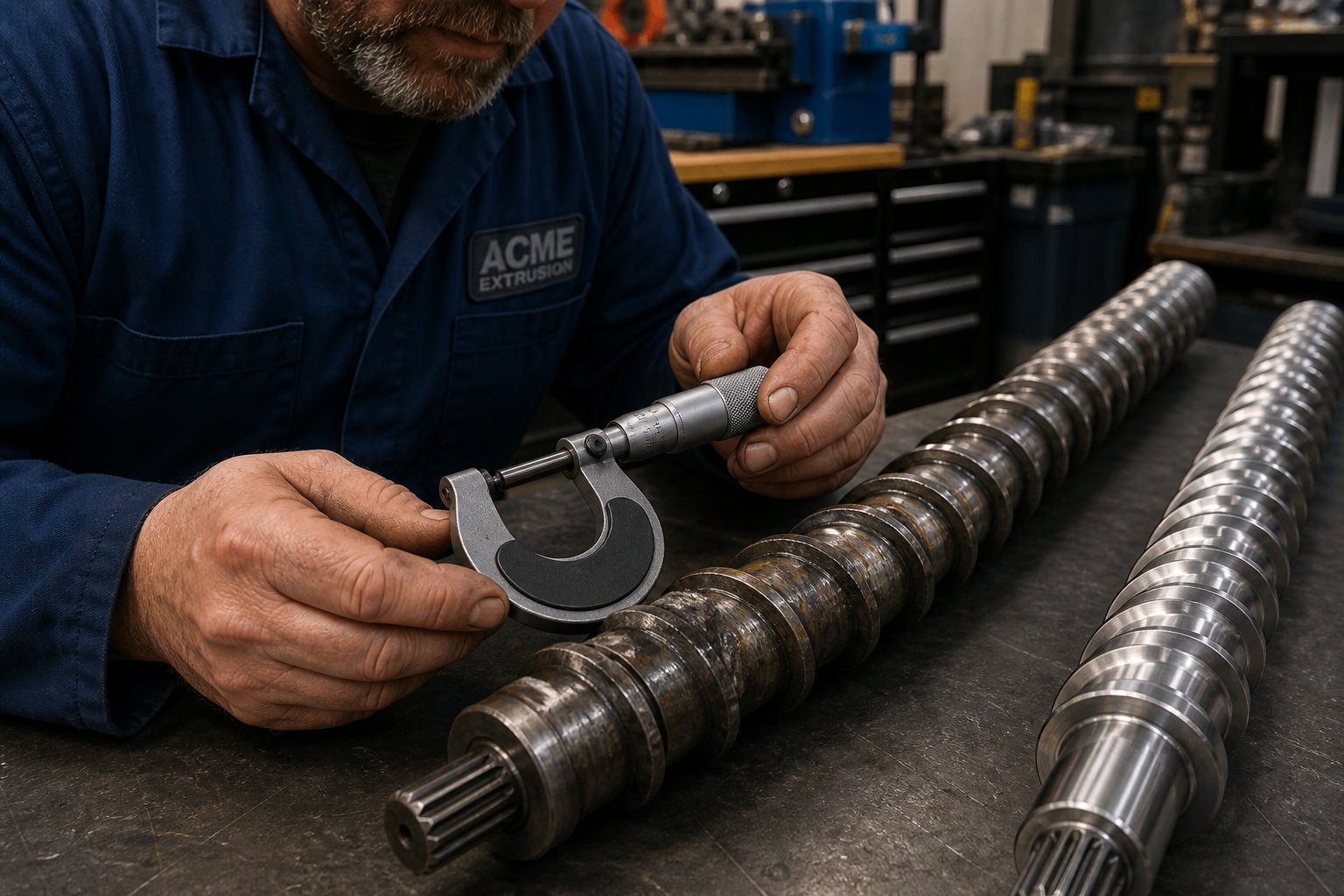
Knowing how to measure extruder screw and barrel wear is the foundation of preventive maintenance. The key measurements are screw flight outside diameter (OD) and barrel bore inside diameter (ID), taken at multiple points along the length. When new, the radial clearance between flight OD and barrel ID is typically 0.001 inch per side per inch of screw diameter. As that clearance increases, melt leaks backward over the flight land instead of being pumped forward, reducing effective throughput and mixing efficiency.
An extruder low throughput root cause analysis should always include a wear check. If you find yourself gradually increasing screw speed, raising barrel temperatures, or adjusting back pressure to maintain the same output you once achieved at lower settings, wear is the likely culprit. Those compensating adjustments consume more energy, generate more shear heat, and degrade melt quality — all while masking the underlying problem. Kuhman describes a "point of diminishing returns" where machine adjustments can no longer offset the productivity and quality losses from worn components. Identifying that threshold — whether defined in machine hours, scrap rate, or energy consumption per kilogram — lets maintenance teams schedule replacements proactively rather than running to failure.
Preventive maintenance best practice: measure screw flight OD and barrel bore ID at regular intervals, chart the trend against output and energy data, and order replacement components before the wear curve forces an unplanned shutdown.
Wear data also feeds directly into the next critical decision: whether to replace with a standard off-the-shelf screw or invest in a custom-engineered design that better matches your current polymer, product, and throughput requirements. That replacement decision — along with a step-by-step selection framework — is where operations teams can turn reactive maintenance into a genuine process upgrade.
Selecting and Replacing the Right Screw and Barrel for Your Line
Wear data tells you something needs to change. A spec sheet tells you what is available. But neither answers the question that actually matters: which screw and barrel design will deliver the best combination of output, melt quality, and service life for your specific polymer, product, and production target? Too many replacement decisions default to "order the same thing again" — which makes sense only if the original screw was well-matched in the first place. Every replacement is also an opportunity to upgrade, and a structured selection framework turns that opportunity into measurable gains.
The following step-by-step approach walks you through how to select the right extruder screw design by narrowing decisions in the order that matters most — from the polymer to the product to the production volume to the budget.
Matching Screw Design to Polymer and Product Type
Extruder screw selection by polymer type is the logical starting point because the resin's thermal behavior constrains every downstream design choice. Ask yourself two questions before anything else: Is the polymer semi-crystalline or amorphous? And how thermally sensitive is it?
- Step 1 — Identify the polymer class and set the compression ratio range. Semi-crystalline resins (HDPE, PP, nylon, PET) undergo a sharp solid-to-liquid transition and require compression ratios in the 3:1 to 4:1 range to ensure complete melting. Amorphous polymers (polycarbonate, PMMA, PS, rigid PVC) soften gradually and tolerate — indeed demand — lower ratios of 1.5:1 to 2.5:1 to avoid excessive shear heating. PVC sits at the extreme end of thermal sensitivity: its decomposition temperature is so close to its processing temperature that compression ratios above 2:1 risk generating hydrochloric acid and discoloring the product.
- Step 2 — Match L/D ratio and mixing requirements to the product form. The product you are making determines how much barrel length you need and what type of mixing the screw must deliver. Pipe extrusion typically performs well at 24:1 to 30:1 L/D with a barrier flight design to prevent solid-bed breakup. Blown film pushes that range to 30:1 or higher because thin gauges magnify every melt imperfection — a distributive mixer after the barrier section is close to mandatory. Sheet extrusion sits in a similar range but is slightly more forgiving on mixing intensity. Compounding and pelletizing lines, especially on co-rotating twin-screw platforms, routinely run 36:1 to 48:1 L/D to provide room for multiple kneading zones, venting ports, and side feeders.
- Step 3 — Size the screw diameter to your throughput target. Output scales approximately with the square to the cube of the diameter ratio, depending on screw design and polymer viscosity. A 60 mm single-screw extruder processing HDPE might deliver 80 to 200 kg/hr, while a 90 mm machine on the same resin can reach 250 to 600 kg/hr. If your target throughput falls between available diameter increments, the general principle is to select the larger diameter and run it at moderate speed. Running a smaller screw at maximum RPM to squeeze out extra output raises melt temperature, accelerates wear, and narrows your process window — a poor tradeoff for a few thousand dollars saved on the initial purchase.
- Step 4 — Factor in budget, maintenance cycle, and total cost of ownership. Capital cost is real, but it is not the whole story. A screw and barrel specified with the right base steel, surface treatment, and wear protection will outlast a cheaper alternative by multiples — and the downtime, scrap, and energy penalty from running worn components accumulate far faster than most operations realize. As industry engineering teams emphasize, the cheapest screw that wears out in months is more expensive than the properly specified one that runs for years. Evaluate cost per operating hour, not purchase price.
When Custom Screw Engineering Outperforms Standard Options
A standard off-the-shelf screw — typically a general-purpose three-zone design with square pitch and a compression ratio around 2.5:1 to 3:1 — handles a surprising range of everyday extrusion work. If you are processing an unfilled commodity polymer on a straightforward pipe or sheet line and the original screw performed adequately, ordering the same geometry again is a perfectly reasonable decision.
Custom screw engineering earns its place when the standard geometry leaves performance on the table. You should seriously consider a custom vs. standard extruder screw replacement in these situations:
- Specialty polymers or filled systems. Glass-fiber-reinforced nylon, mineral-filled polyolefins, wood-plastic composites, and recycled feedstocks all impose demands that a general-purpose screw cannot meet efficiently. Barrier flights, optimized compression profiles, and application-specific mixing sections improve melt quality and reduce the wear rate that abrasive fillers inflict on standard designs.
- High-volume production lines. On a line running 24/7, even a 3-5% improvement in specific output — kilograms per screw revolution — translates to thousands of kilograms of additional product per month. Custom screw geometry tuned to the actual polymer viscosity curve and the die's pressure requirement captures that gain. The payback period on the engineering investment is often measured in weeks, not years.
- Persistent quality problems. If your troubleshooting table from the previous chapter keeps pointing back to gels, unmelted particles, or thermal degradation despite correct machine settings, the screw geometry itself may be the root cause. A screw designed for LDPE will not perform well on LLDPE, even though both are "polyethylene." Custom engineering matches the screw's channel depths, transition profile, and mixing elements to the specific resin grade you actually run.
- Material or product changes since the original screw was specified. Production lines evolve. A pipe line originally designed for virgin HDPE may now process 30% regrind. A film line specified for LDPE may have switched to a metallocene LLDPE that demands higher torque and more mixing. When the material changes, the screw should change with it.
For operations managing multiple extrusion line types — pipe, profile, film, sheet, and pelletizing — sourcing custom screws and barrels from a supplier who covers that full range simplifies engineering coordination and ensures design consistency. NANHAIYA's screw barrel support, for example, spans all of these configurations and provides custom-engineered replacements matched to specific line types and polymers. This kind of application-specific capability is worth evaluating alongside general-purpose suppliers, especially for maintenance teams that need replacement components to arrive ready to drop in — not require trial-and-error optimization on the production floor.
Measuring Wear and Deciding When to Replace
Knowing when to replace a worn extruder screw and barrel is ultimately an economic decision — but it must be grounded in physical measurement, not guesswork. Here is a practical framework for turning wear data into an actionable replacement timeline.
What to measure and how often. Pull the screw at least annually — more frequently if you process abrasive or corrosive materials. Measure the screw flight outside diameter (OD) at multiple points along the length using a micrometer or go/no-go gauge, and measure the barrel bore inside diameter (ID) using a telescoping bore gauge. Record the values and chart them over time. As Plastics Technology's wear analysis details, the as-new radial flight clearance is approximately the nominal screw diameter divided by 1,000 per side. For a 90 mm screw, that means roughly 0.09 mm per side when new.
Understanding wear thresholds. There is no single universal number that defines "worn out" — the acceptable wear level depends on how demanding your application is. Industry practices range from replacing the screw when flight clearance reaches 2x the original value (critical applications like medical tubing or optical film) to tolerating 4x or more for non-critical products like corrugated drainage pipe. The key insight from Spalding and Womer's research is that the best replacement decision is economic, not geometric: replace when the combined cost of lost throughput, increased energy consumption, elevated scrap rate, and degraded product quality exceeds the cost of a new or refurbished screw.
Consider a concrete example from their analysis: a 100 mm screw running 1 MI polyethylene at 150 kg/hr. When new, the flight clearance was 0.005 inches per side and discharge temperature held at 236 degrees Celsius. After the clearance increased to 0.016 inches from wear, maintaining 150 kg/hr required significantly higher screw speed, and the discharge temperature climbed toward 246 degrees Celsius — too hot for a blown film process. The operator's only option was to reduce throughput by roughly 13%, cutting both profitability and line capacity.
Screw and barrel wear as a system. A critical and often overlooked principle: the screw and barrel wear as a matched pair. Installing a new screw into a worn barrel does not restore the original clearance — the oversized bore creates the same leakage path regardless of how sharp the new screw's flights are. Measurement of both components before ordering a replacement is essential. As a general guideline, an iron-based bimetallic barrel liner lasts approximately three times the service life of a screw, so barrel replacement is less frequent but must be checked at every screw pull. When in doubt on a high-hour machine, ordering a matched screw-and-barrel set avoids the disappointment of putting a perfect screw into a barrel that cannot support it.
Refurbish or replace? A worn screw can often be rebuilt — flight tips re-hardfaced, OD ground back to spec, and chromed. This is typically 40-60% the cost of a new screw and extends useful life significantly. However, a screw should generally not be refurbished more than three times, because repeated welding of hardfacing onto the base metal degrades the substrate and increases the risk of delamination during service. After three rebuilds, a new screw is the safer and more economical choice.
Replace based on economics, not just geometry: when lost throughput, higher energy use, and increased scrap cost more than a new screw and barrel, the worn components have reached their service limit — regardless of how much metal remains.
Every section of this guide — from the three-zone melting process through screw geometry, machine configurations, specifications, applications, downstream matching, and troubleshooting — converges on this final point: the screw and barrel are not generic spare parts. They are precision-engineered components whose design must be matched to the polymer, the product, and the process. Get that match right, and the plasticating unit disappears into reliable, profitable production. Get it wrong, and it announces itself in wear, defects, and downtime. Armed with the frameworks in this resource, you are equipped to make that match with confidence — whether you are specifying a new line, optimizing an existing one, or deciding that a worn screw has finally earned its retirement.
Frequently Asked Questions About Screw Plastic Extruders
1. What is the difference between a single-screw and a twin-screw plastic extruder?
A single-screw extruder uses one rotating screw inside a barrel and excels at steady-state processing of individual polymers for pipe, film, profile, and sheet production at lower capital cost. A twin-screw extruder uses two intermeshing screws — either co-rotating for intensive compounding and reactive extrusion, or counter-rotating for gentle processing of heat-sensitive materials like PVC. Twin-screw machines offer superior mixing, modular screw configurations, and independent speed-throughput control, but they carry higher purchase and maintenance costs. The choice depends on your formulation complexity, mixing requirements, and whether frequent material changeovers are needed.
2. How does the compression ratio of an extruder screw affect processing?
The compression ratio — the feed-zone channel depth divided by the metering-zone channel depth — controls how aggressively the screw compacts and melts the polymer. Semi-crystalline resins like HDPE, PP, and nylon require higher ratios (3:1 to 4:1) because they undergo a sharp solid-to-liquid phase change that demands intense mechanical energy. Amorphous polymers such as polycarbonate, PMMA, and rigid PVC soften gradually and need lower ratios (1.5:1 to 2.5:1) to avoid thermal degradation from excessive shear heating. Always pair compression ratio with at least one absolute channel depth measurement for a meaningful screw comparison.
3. What does the L/D ratio mean on a screw plastic extruder?
The L/D ratio is the screw's active flighted length divided by its diameter. Common values range from 24:1 to 36:1 for single-screw extruders and 20:1 to 48:1 for twin-screw machines. A higher L/D ratio provides more barrel length for melting, mixing, and pressure development, which benefits filled compounds, reactive extrusion, and devolatilization. However, longer screws increase capital cost, floor space, purge time, and torque demand. For thermally sensitive materials, shorter ratios keep residence time brief and reduce degradation risk. Matching L/D to your polymer and product type is one of the most impactful specification decisions during machine evaluation.
4. How do you know when an extruder screw and barrel need replacement?
Measure screw flight outside diameter and barrel bore inside diameter at regular intervals — at least annually, or more often with abrasive or corrosive materials. When new, radial flight clearance is roughly 0.001 inch per side per inch of screw diameter. As wear increases this clearance, melt leaks backward over flights, reducing effective throughput and mixing. The best replacement trigger is economic: when the combined cost of lost output, higher energy consumption, elevated scrap, and degraded product quality exceeds the cost of new or refurbished components. Suppliers like NANHAIYA offer custom-engineered replacement screws and barrels matched to specific line types at https://www.nhyscrews.com/products/plastic-extruder-machine, helping maintenance teams avoid trial-and-error fitting on the production floor.
5. What causes surging or uneven output in a screw extruder?
Surging — cyclical output fluctuation at constant setpoints — most commonly originates from improper temperatures in the solids conveying section. An overheated feed casing or screw causes pellets to melt prematurely on metal surfaces, collapsing the frictional grip that drives forward conveyance. Other root causes include worn metering-zone flights that increase back-leakage, feed throat bridging from moisture or fines, inconsistent pellet bulk density, and incorrect barrel temperature profiles. A quick diagnostic check involves touching the feed casing (it should feel warm, not hot) and verifying that screw cooling water is actually flowing at the correct rate.
Written by
Nanhaiya Technical Team
Zhoushan Nanhaiya Plastic Machinery Co., Ltd.
The Nanhaiya technical team supports screw and barrel manufacturing projects through application review, technical communication, custom manufacturing coordination, and production and quality control.
Discuss Your Application
Related Articles
More insights on screw barrel technology and plastics processing.

What Nobody Tells You About Screw Barrel For Plastic Machine Design
Oct 10, 2026
Learn how screw barrel for plastic machine design affects melt quality, throughput, and wear life. Covers geometry, resin matching, troubleshooting, and sourcing.
Read Article
Single Screw Extruder for Sheet: Stop Guessing, Start Specifying
Oct 9, 2026
Learn how to specify a single screw extruder for sheet production. Covers screw geometry, resin-specific processing, troubleshooting, and maintenance best practices.
Read Article
PE Pipe Extruder Machine: What Datasheets Won't Tell You
Oct 9, 2026
Learn how a PE pipe extruder machine works, key specs explained, material grade selection, maintenance tips, and buyer guidance beyond the datasheet.
Read ArticleLooking for something else?
Search by material, symptom or product and jump straight to the relevant page.
These are navigation suggestions based on keyword matching — not a quotation, not a delivery commitment, and not a substitute for engineering review. Final specification is confirmed by our engineers against your drawings and processed material.
Need help with screw barrel selection?
Share your machine model, processed material and application. Our team can help with pricing and technical support.