

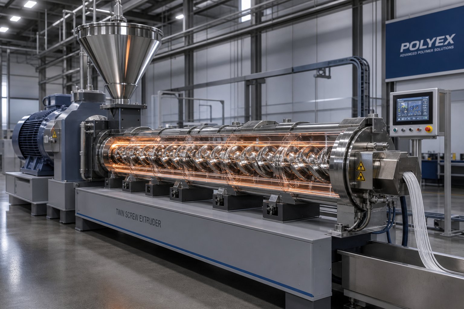
What Is a Screw Extruder and Why It Matters
Imagine feeding plastic pellets into one end of a machine and watching a perfectly shaped pipe, film, or sheet emerge from the other. That transformation is exactly what a screw extruder makes possible every day in factories around the world.
A screw extruder is a machine that uses one or more rotating screws inside a heated barrel to melt, mix, and continuously force raw materials—primarily thermoplastic polymers—through a shaped die. It converts solid feedstock into uniform profiles, pellets, films, or sheets in a single, uninterrupted process.
What Is a Screw Extruder and How Does It Work
At its core, every extruder screw operates through four functional zones that work in sequence:
- Feed zone: Solid pellets or powder enter through a hopper and are conveyed forward by the rotating extrusion screw. The channel depth here is deep enough to accept bulk material efficiently.
- Compression (transition) zone: The screw channel gradually becomes shallower, compacting the material, squeezing out trapped air, and initiating melting through a combination of barrel heat and intense frictional shear.
- Metering zone: A shallow, constant-depth channel ensures the now-molten polymer is fully homogenized and delivered at a consistent pressure and flow rate toward the die.
- Die: The molten material is forced through a precision-engineered opening that determines the final cross-sectional shape of the product—whether that is a round pipe, a flat sheet, or a thin film.
Each zone plays a distinct role, yet they function as an integrated system. A well-designed screw balances conveying, melting, and pressure generation so the die receives a thermally uniform, bubble-free melt at the right flow rate.
Why Screw Extruders Matter in Modern Manufacturing
Screw extrusion is not limited to plastics. Food manufacturers rely on similar equipment to texturize snacks and cereals. Pharmaceutical companies use it for hot-melt drug delivery systems. Recycling facilities depend on robust extruder screws to reprocess post-consumer waste into reusable pellets. Even advanced composite and nano-material research hinges on precise screw extrusion processes.
Why does this breadth matter to you? Because understanding how the machine actually works—how screw geometry, barrel heating, and material behavior interact—gives operators sharper troubleshooting instincts, helps engineers specify the right equipment, and equips procurement teams to evaluate suppliers with confidence rather than guesswork.
That foundational knowledge starts with knowing where the technology came from and how it evolved into the sophisticated systems running production lines today.
A Brief History of Screw Extrusion Technology
Every modern extrusion line owes a debt to machines that were never designed for plastics at all. The screw extruder's family tree stretches back over a century, rooted in industries that look nothing like today's polymer processing plants.
Early Origins of Screw-Based Material Processing
In the late 1800s and early 1900s, machine builders in Germany and England began developing screw-based equipment for rubber compounding. Companies like Werner & Pfleiderer and Banbury built early machinery designed to knead and mix natural rubber—long before synthetic polymers entered the picture. These single-screw designs relied on drag flow and frictional heat to process viscous materials, and they set the mechanical blueprint for everything that followed.
The real turning point arrived during World War II. The urgent demand for synthetic rubbers and thermoplastics drove companies like Union Carbide to accelerate research into new materials—and the existing rubber processing machines suddenly needed to handle an entirely different class of feedstock. By the 1930s through the 1950s, the rise of thermoplastics forced engineers to rethink screw geometry, barrel heating, and process control from the ground up.
The Rise of Twin Screw Technology
Single screw designs excelled at melting and conveying, but they struggled with intensive mixing and compounding tasks. That limitation sparked a pivotal innovation. In 1943, Rudolf Erdmenger and Walter Meskat began work on intermeshing screw concepts at the IG plant in Wolfen, Germany. By 1945, Erdmenger had developed the fully self-wiping profile for co-rotating intermeshing twin screws—a breakthrough that remains the foundation of modern twin screw extrusion.
In 1953, Werner & Pfleiderer acquired an exclusive license from Bayer to commercialize Erdmenger's design. Four years of intensive development followed, and in 1957, the first Werner & Pfleiderer twin screw extruder—the ZSK—was delivered to a customer. This Werner & Pfleiderer extruder became the forefather of all co-rotating twin screw compounding machines. The twin screws offered something single designs simply could not: self-wiping action, modular screw elements, and the flexibility to handle a vast range of formulations.
The decades that followed brought rapid refinement. Here are the key milestones that shaped the technology into what you see on factory floors today:
- Late 1800s–early 1900s: German and English machine builders develop screw-based rubber compounding equipment.
- 1930s–1940s: World War II accelerates synthetic polymer research; thermoplastics demand new extruder designs.
- 1943–1945: Erdmenger develops the self-wiping co-rotating twin screw profile.
- 1953: Werner & Pfleiderer licenses Erdmenger's design from Bayer; development of the ZSK begins.
- 1957: The first Werner & Pfleiderer twin screw extruder (ZSK) is delivered for commercial use.
- 1970s: DuPont advances the mechanical understanding of twin screw geometry; two-lobe configurations increase throughput and surface area.
- 1990s: Advanced fluid-mechanics modeling enables simulation-driven screw profile optimization.
- 2000s–present: Specific torque values climb from 3.7 to 18 Nm/cm³, speeds reach 1,200+ RPM, and throughput increases by a factor of 35 for the same shaft center distance.
Today, the trajectory points toward even more specialized territory. Twin screw extrusion is expanding into reactive extrusion for in-situ polymerization, nano-composite processing where dispersion quality is measured in nanometers, and pharmaceutical continuous manufacturing using hot-melt extrusion and twin-screw granulation. These applications demand the kind of precise mixing control and modular flexibility that only twin screws deliver.
Yet the machines powering these innovations still share fundamental DNA with those early rubber-processing screws. What has changed—dramatically—is how engineers design and configure the screws themselves, which raises a practical question: how do single screw and twin screw systems actually differ in architecture, and when should you choose one over the other?
Single Screw vs Twin Screw Extruder Types
The answer to that question—single or twin—shapes everything from capital investment to product quality. Yet the two architectures are not simply "one screw versus two." They differ in how they convey, melt, mix, and pressurize material. Getting the distinction right is the first step toward specifying the machine that actually fits your process.
Single Screw Extruder Design and Strengths
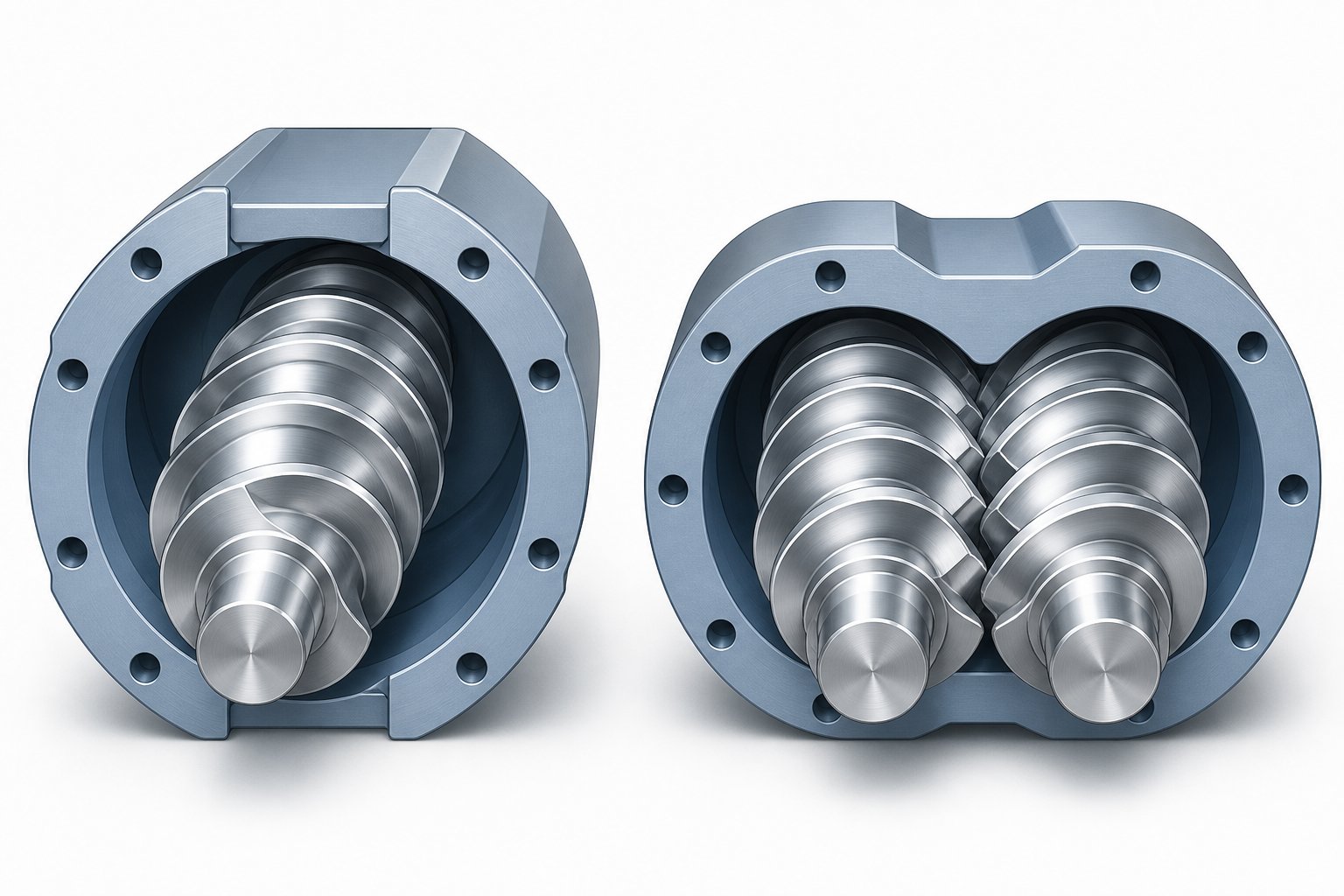
A single screw extruder features one helical screw rotating inside a cylindrical barrel—smooth-bore or grooved in the feed section—driven by a geared motor. Its operating principle is straightforward: drag flow generated between the rotating screw flights and the stationary barrel wall moves material forward, while barrel heaters and frictional shear handle melting.
That simplicity is actually its greatest advantage. Single screw extrusion systems have fewer moving parts, lower purchase costs, and less demanding maintenance schedules than their twin screw counterparts. They excel when the incoming material is already pre-compounded and requires reliable melting, homogenization, and pressure generation rather than intensive mixing. Think pipe, profile, blown film, cast film, and sheet lines—applications where melt consistency and stable output pressure matter more than dispersive blending.
Limitations appear when you need to incorporate high filler loadings, blend immiscible polymers, or carry out reactive chemistry inside the barrel. A single screw simply cannot generate the complex shear and elongational flow fields required for those tasks.
Twin Screw Extruder Configurations Explained
When processing demands move beyond what a single screw can deliver, engineers turn to twin screw extruders—sometimes called double screw extruders in general industry terminology. Two screws working together inside a figure-eight barrel bore unlock mixing capabilities that a single flight path cannot replicate. But not all twin screw designs serve the same purpose. Three primary configurations dominate industry use:
- Co-rotating intermeshing (parallel): Both screws turn in the same direction with fully intermeshing flights. Material follows a figure-eight path between screws, creating a powerful self-wiping action that virtually eliminates dead zones. This is the most versatile and widely used twin screw extruder type, ideal for compounding, masterbatch production, reactive extrusion, and devolatilization. Modular screw element designs allow engineers to tailor the screw profile for each formulation.
- Counter-rotating intermeshing (conical or parallel): The screws rotate in opposite directions. A conical twin screw extruder—where the screws taper from a large feed diameter to a smaller discharge end—is the workhorse for rigid PVC pipe and profile extrusion. The converging geometry naturally builds die pressure while the opposing rotation keeps shear stress low, protecting heat-sensitive materials from degradation.
- Counter-rotating non-intermeshing (parallel): The screws operate independently without mechanical engagement. This configuration offers the highest free volume and the gentlest shear of any twin screw design, making it well suited for high-level devolatilization, specialty chemical processing, and pharmaceutical hot-melt extrusion where residence time control is critical.
Co-Rotating vs Counter-Rotating Performance Differences
Understanding co rotating and counter rotating twin screw extruder differences comes down to what happens at the intermeshing zone—the heart of the machine.
In a co rotating twin screw extruder, material at the intermeshing region is forcibly handed off from one screw to the other, creating intense shear fields and an elongational flow component that excels at breaking up filler agglomerates and distributing additives. Speeds commonly reach 400 to 900 RPM, and some high-performance models exceed 1,200 RPM. The self-wiping geometry keeps the barrel clean, shortens color and material changeover times, and maintains a narrow residence time distribution—critical for reactive extrusion and thermally sensitive formulations.
Counter-rotating designs take a fundamentally different approach. At the intermeshing zone, the opposing screw rotation draws material inward and compresses it, producing a calendering effect that disperses additives under relatively gentle conditions. A parallel twin screw extruder in counter-rotating mode typically runs at much lower speeds—often 30 to 150 RPM—which minimizes shear heating. This makes the counter-rotating configuration the natural choice for materials like rigid PVC, where the thermal decomposition temperature sits uncomfortably close to the processing window.
The table below puts all four major configurations side by side so you can see exactly where each one excels—and where it falls short.
| Parameter | Single Screw | Co-Rotating Twin Screw (Parallel) | Counter-Rotating Twin Screw (Parallel) | Conical Twin Screw (Counter-Rotating) |
|---|---|---|---|---|
| Mixing Capability | Limited; primarily distributive | Excellent; both dispersive and distributive | Moderate; calendering-based dispersion | Moderate; gentle compressive mixing |
| Throughput Potential | Moderate | Highest (high-speed operation) | Lower; speed-limited | Moderate; pressure-optimized |
| Shear Intensity | Low to moderate | High; adjustable via screw profile | Low | Low |
| Self-Wiping Ability | None | Excellent | Partial | Partial |
| Modular Flexibility | Limited | Highly modular (interchangeable elements) | Some modularity | Minimal; fixed screw geometry |
| Heat-Sensitive Material Suitability | Good (low shear) | Requires careful screw design | Very good | Excellent (PVC specialist) |
| Relative Equipment Cost | Lowest | Highest | Moderate to high | Moderate |
| Primary Applications | Pipe, profile, film, sheet extrusion | Compounding, masterbatch, reactive extrusion, devolatilization | Devolatilization, specialty processing | PVC pipe, PVC profile, WPC |
Notice the pattern: single screw machines win on simplicity and cost for forming operations, while a twin-screw extruder dominates wherever mixing intensity and formulation flexibility are priorities. The co-rotating parallel design offers the broadest application range, but counter-rotating and conical configurations remain indispensable for specific material families—especially PVC.
Choosing the right architecture, however, is only half the equation. The real performance of any extruder lives in the engineering details hidden inside the barrel: the screw's length-to-diameter ratio, its compression ratio, flight depth, and pitch. These parameters determine whether a well-chosen machine type actually delivers the melt quality your product demands.
Critical Screw Design Parameters That Drive Performance
A co-rotating twin screw and a single screw may sit side by side on a factory floor, yet their output quality can differ dramatically—not because of the architecture alone, but because of a handful of geometric parameters engineered into each screw's steel. These dimensions control how material melts, how thoroughly it mixes, and how consistently it reaches the die. Sounds technical? It is—but the logic behind each parameter is surprisingly intuitive once you break it down.
Length-to-Diameter Ratio and Its Impact on Processing
The L/D ratio—flighted screw length divided by its outer diameter—is the single most-quoted specification for any extruder. Think of it as the machine's runway: a longer runway gives the material more time and more processing stages before it exits the die.
For single screw systems, standard L/D ratios range from roughly 20:1 to 36:1, with most general-purpose machines falling between 24:1 and 30:1. Twin screw compounding extruders stretch further—commonly 32:1 to 48:1—because their modular barrel sections make it practical to add melting, mixing, venting, and pressure-building stages in sequence.
A higher L/D ratio delivers more residence time, more heat transfer area, and room for additional mixing or devolatilization zones. But longer is not automatically better. Excessive L/D increases energy consumption, raises manufacturing precision requirements, and heightens the risk of shaft deflection—where the screw flexes enough to contact the barrel wall, accelerating wear on both components. For thermally sensitive polymers like PVC, a shorter L/D is often preferred precisely because it limits heat exposure and reduces degradation risk.
Compression Ratio, Flight Depth, and Screw Pitch
If L/D sets the runway length, the compression ratio determines how aggressively the material is squeezed along the way. Defined as the ratio of the feed zone channel depth to the metering zone channel depth, this number typically falls between 2:1 and 4:1 for most thermoplastics. A polyethylene screw, for example, might use a compression ratio of 3:1 to 4:1, while a rigid PVC formulation using granules often requires a gentler 2:1 to 3:1 to avoid scorching.
Why does this matter in practice? Too high a compression ratio overheats sensitive resins and can cause degradation. Too low, and you'll find unmelted pellets reaching the metering zone—a defect that shows up immediately in your finished product. The compression ratio must be matched to the material's physical compression ratio, which is the relationship between the final melt density and the apparent bulk density of the incoming feedstock.
Flight depth—the radial distance between the screw root and flight tip—works hand in hand with compression ratio. Deeper channels in the feed zone accept more bulk material per revolution, improving throughput. Shallower channels in the metering zone generate higher shear rates, promoting heat transfer and melt homogeneity, but excessively shallow grooves can restrict output volume.
Screw pitch—the axial distance between consecutive flights—controls how fast material moves forward per rotation. Most extruder screws use a "square pitch" design where pitch equals the screw diameter, but variations exist. A wider pitch accelerates conveying but reduces residence time; a tighter pitch slows material down, giving it more exposure to barrel heat. Adjusting pitch also changes the helix angle, which affects both conveying efficiency and plasticization quality. In practice, a helix angle of approximately 17°40' is commonly used as a practical compromise for the metering zone.
How Barrel and Screw Geometry Work Together
You cannot evaluate extruder screws in isolation. The barrel is not just a container—it is an active processing partner. Every parameter described above only produces the intended result when the extruder screw and barrel work as a matched system.
Consider barrel bore tolerance first. The clearance between the screw flight outer diameter and the barrel inner wall is typically controlled within 0.1 to 0.6 mm. When that gap grows—through wear, misalignment, or manufacturing variance—molten polymer leaks backward past the flights. The result is reduced output, higher melt temperatures from increased frictional reheating, and degraded product quality. In a twin screw barrel, bore geometry is even more critical because both bores must maintain concentricity and figure-eight alignment to preserve the intermeshing relationship.
Barrel heating and cooling zones add another dimension. Independent temperature control across multiple zones lets operators create a thermal profile that complements the screw's mechanical work. In many extrusion setups, shear heating accounts for 60 to 80 percent of total energy input, meaning the barrel's heaters are often supplementing or moderating the heat the screw itself generates. Wear-resistant barrel linings—nitrided steel for general processing, bimetallic alloys for abrasive compounds—protect the bore surface that directly governs that critical flight-to-wall clearance.
The table below summarizes how these parameters interact to shape processing performance.
| Parameter | Definition | Typical Range | Processing Effect |
|---|---|---|---|
| L/D Ratio | Flighted screw length divided by screw diameter | 20:1–36:1 (single screw); 32:1–48:1 (twin screw) | Higher L/D increases melting capacity, mixing stages, and residence time; excessive L/D raises degradation risk and energy consumption |
| Compression Ratio | Feed zone channel depth divided by metering zone channel depth | 2:1–4:1 (material-dependent) | Controls melt pressure and plasticization intensity; must match material bulk density and thermal sensitivity |
| Flight Depth (Channel Depth) | Radial distance between screw root and flight tip | Varies by zone and diameter; deeper in feed, shallower in metering | Deeper channels increase throughput but reduce shear; shallower channels improve mixing and heat transfer |
| Screw Pitch | Axial distance between consecutive flights | Often equal to screw diameter (square pitch); adjusted for specific needs | Wider pitch increases conveying speed; narrower pitch extends residence time and improves plasticization |
| Helix Angle | Angle between the screw flight and the screw's cross-sectional plane | ~17°40' most common; 30° for powder feed sections | Affects conveying efficiency, screw groove volume, and plasticization quality |
| Screw-to-Barrel Clearance | Radial gap between flight OD and barrel ID | 0.1–0.6 mm | Tight clearance minimizes backflow and leakage; excessive clearance causes output loss, overheating, and degradation |
Notice how every parameter in that table connects back to the one next to it. Changing the compression ratio without adjusting flight depth alters the shear profile. Extending L/D without reconsidering the twin screw and barrel thermal zone layout can overheat sensitive formulations. This interdependence is why a barrel extruder system must be engineered as a complete package—screw geometry, barrel construction, and thermal management designed together rather than specified in isolation.
These fixed geometric parameters define the baseline capability of any screw extruder. But modern twin screw machines take flexibility a step further: modular screw elements that can be rearranged on a splined shaft to create entirely different processing profiles without machining a new screw. That modularity is where extrusion engineering becomes truly powerful—and precisely tunable.
Modular Screw Elements and Configuration Principles
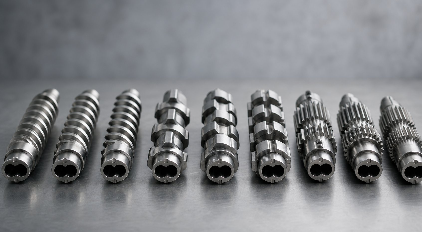
Fixed screw geometry gets you into the game. Modular screw elements let you rewrite the rules. On a twin screw compounding extruder, individual segments slide onto a splined shaft and lock into position—meaning engineers can rebuild the entire processing profile in a few hours without fabricating a new screw. This modularity is the reason co-rotating twin screw machines dominate compounding, reactive extrusion, and specialty processing. But which elements go where, and why?
Conveying, Kneading, and Mixing Elements Explained
Every modular screw profile draws from three primary element families, each engineered for a distinct job.
Conveying elements transport material forward through the barrel. Their deep-flighted helical geometry moves feedstock efficiently while generating relatively low shear. As NC State Extension research explains, the deeper channel of a conveying element enables efficient material transport to subsequent extruder sections without significantly breaking down ingredients. Pitch matters here: a larger pitch element increases throughput but reduces pressure-building capability, while a shorter pitch raises the local fill level and boosts pressure generation. Reverse conveying elements—left-handed versions of the same geometry—intentionally push material backward to create localized restriction, seal melt zones before vacuum vents, and increase residence time in upstream mixing sections.
Kneading blocks are the heart of any compounding extruder's mixing capability. These consist of multiple disc-shaped lobes staggered at specific angular offsets along a short segment. The stagger angle is the critical variable that separates gentle blending from aggressive dispersion:
| Stagger Angle | Mixing Intensity | Conveying Effect | Shear Level | Typical Use |
|---|---|---|---|---|
| 30° | Moderate | Forward conveying maintained | Medium | Initial melting, gentle blending |
| 45° | High | Balanced | High | General-purpose compounding |
| 60° | Very high | Reduced conveying | Very high | Filler dispersion, polymer blending |
| 90° (neutral) | Maximum | Minimal (no forward push) | Extreme | Aggressive dispersive mixing, melt sealing |
Forward-staggered kneading blocks (right-handed) are less aggressive because they still push material downstream. Neutral 90° elements do not convey at all—they only impart energy and increase residence time, as NC State's screw profile research confirms. Reverse kneading blocks push material backward, creating maximum restriction in forward flow and generating the highest shear intensity. Additionally, disc width plays a role: wider kneading discs promote dispersive mixing by applying stronger shear stress, while narrower discs favor distributive mixing by splitting and recombining the melt stream without as much particle size reduction.
Specialized mixing elements fill gaps that standard kneading blocks cannot cover. Toothed mixing elements (TME or ZME) use gear-like tooth geometries to repeatedly split and recombine the melt flow, delivering excellent distributive mixing with tightly controlled temperature rise. These are particularly valuable in the twin screw extrusion process for color masterbatch, liquid additive injection, and polymer blends where you need uniform spatial distribution without excessive shear heating. Unlike kneading blocks, toothed elements can achieve high-quality distributive mixing with near-zero dispersive effect—a critical distinction when processing shear-sensitive formulations.
Configuring a Screw Profile for Specific Processing Goals
Imagine the splined shaft as a blank canvas. An engineer's job is to arrange conveying, kneading, and mixing elements along its length to create distinct process sections, each targeting a specific transformation. The arrangement is never random—it follows the material's journey from raw feedstock to pressurized melt.
Here is how a typical compounding twin screw extruder profile might look from feed throat to die, broken into functional zones:
- Solids conveying zone (barrels 1–2): Large-pitch conveying elements accept bulk material from the feeder, transport it forward, and begin initial densification. Open barrel venting here allows displaced air to escape.
- Melting/plasticization zone (barrels 3–4): Conveying elements transition to progressively shorter pitch, followed by a forward kneading block sequence (30° then 45° stagger). The combination of increasing compression and kneading-disc shear initiates and completes melting.
- Intensive mixing zone (barrels 5–6): Wider 60° or 90° kneading blocks deliver dispersive mixing to break up filler agglomerates or create fine polymer blend morphologies. A short reverse element or reverse kneading block at the end of this zone creates a melt seal—essential if a vacuum vent follows.
- Venting/degassing zone (barrel 7): Deep-flighted conveying elements with large pitch reduce fill level and expose maximum melt surface area to applied vacuum, allowing moisture, volatiles, and entrapped air to escape.
- Distributive mixing zone (barrel 8): Toothed mixing elements or narrow kneading blocks homogenize the melt without adding excessive shear energy—ideal for final color distribution or additive blending.
- Pressure build-up zone (barrels 9–10): Short-pitch conveying elements with progressively tighter flights compress and pressurize the melt to overcome die resistance and deliver consistent output.
This sequence is not fixed. A reactive extrusion profile might add a second intensive mixing zone downstream of a liquid injection port. A devolatilization-heavy process could include multiple venting zones separated by melt seals. The entire point of modularity is that you adapt the screw to the process—not the other way around.
One practical nuance worth noting: the concept of process sections aligns with how engineers think about a twin screw extruder as a series of unit operations strung along a single shaft. Feeding, melting, mixing, venting, and pressure generation each occupy a defined region, and the transitions between them are deliberately managed through element selection.
How Screw Configuration Affects Energy and Output Quality
Here is where extrusion transitions from equipment operation to process engineering. The screw profile you build directly determines the specific mechanical energy (SME)—measured in kWh/kg—transferred from the motor through the screws and into the material. SME is one of the most important scaling parameters in the twin screw extrusion process, and it links screw design decisions to real product outcomes.
A case study published in Plastics Technology illustrates this vividly. During scaleup from a 26-mm laboratory extruder to a 92-mm production machine, directly copying the process conditions caused the SME to drop from 0.083 to just 0.026 kWh/kg—a 69% deficit. The result? Unmelted pellets discharging through the die, phase separation, and a completely unusable product. Only after redesigning the screw profile and feeding configuration to restore SME to approximately 0.086 kWh/kg did the process achieve stable, homogeneous output at full production rates.
The lesson is clear: a screw configuration's quality shows up in three measurable outcomes.
- Dispersion level: More aggressive kneading zones improve filler breakup and color uniformity, but excess shear can degrade fiber length in glass-reinforced compounds or cause thermal decomposition in heat-sensitive polymers.
- Degradation risk: Every kneading block and reverse element adds energy input and residence time. Overdesigning the mixing intensity raises melt temperature beyond the material's safe processing window, leading to molecular weight loss, discoloration, or off-gassing.
- Throughput: Restrictive elements—90° kneading blocks, reverse screws—reduce the effective conveying rate. A profile loaded with too many mixing elements will bottleneck output even if the motor and gearbox can deliver more torque.
Balancing these three outcomes is the central challenge of screw profile engineering. The best configurations deliver just enough mixing energy to meet quality targets while minimizing thermal history and maximizing throughput—a balance that shifts with every new formulation.
Understanding how individual elements combine into a working profile gives you the engineering vocabulary. But a screw profile does not operate in isolation—it is part of a larger system where raw material enters a feed throat and exits as a shaped product. The full picture only emerges when you follow the material's complete journey through every stage of the extrusion process.
The Complete Extrusion Process Step by Step
Knowing what each screw element does is essential. But a screw profile means little if you cannot trace how raw pellets entering the hopper become the finished pipe, film, or pellet strand leaving the production line. Most equipment guides list individual components—motor, barrel, die—without ever explaining how they function as a connected extruder system. That gap leaves operators troubleshooting symptoms instead of root causes. So let's follow the material from start to finish, stage by stage, and see how every part of the process depends on every other.
From Raw Material Feed to Molten Polymer
Everything begins at the feed throat. Thermoplastic pellets, powders, additives, or even liquid components enter the barrel through one of two feeding methods:
- Volumetric feeding delivers material at a constant volume per unit time using a simple auger or vibratory feeder. It is cost-effective but sensitive to bulk density variations—if the pellets pack differently from batch to batch, actual mass flow changes without the system knowing.
- Gravimetric feeding continuously weighs the material as it is dispensed, adjusting the feeder speed in real time to maintain a precise mass flow rate. This is the standard for compounding, pharmaceutical processing, and any application where recipe accuracy directly impacts product quality.
Once inside the barrel, material enters the solids conveying zone. Here, deep-flighted screw elements grip the incoming feedstock and push it forward. Friction between the pellets and the barrel wall is the dominant conveying force in single screw machines—if the barrel surface is too smooth, the material simply spins with the screw and goes nowhere. Grooved feed sections in certain extruder designs dramatically increase this friction, boosting conveying rates but also raising mechanical loads on the drive system.
As the screw channel becomes shallower in the compression zone, pellets compact together, squeezing out interstitial air. Tremendous pressure builds rapidly—easily reaching 400 bar (approximately 6,000 psi) in the compression section. The intense friction between the compacted solid bed and the hot barrel wall, combined with mechanical shear from the rotating screw, generates enough heat to initiate melting. External barrel heaters supplement this energy, but in many polymer extruder configurations, shear heating accounts for 60 to 80 percent of total energy input. The screw is not just conveying material—it is the primary heat source.
Here is where a concept most equipment guides ignore becomes critically important: polymer rheology. Thermoplastic melts are non-Newtonian, viscoelastic fluids. Their viscosity is not a fixed number—it drops significantly as shear rate increases, a behavior known as shear thinning. This property has direct, practical consequences for every extruder for polymer processing:
- At low screw speeds, the melt viscosity is high, meaning more motor torque is required to push the same volume of material. Pressure generation is strong, but throughput is limited.
- At high screw speeds, shear rates climb and viscosity drops. Material flows more easily, throughput increases, but the reduced viscosity also means reduced pressure-generating capability per revolution—so the die and downstream restrictions must be balanced accordingly.
The degree of shear thinning varies dramatically between polymers. As TA Instruments' polymer melt rheology research explains, polymers with a broader molecular weight distribution tend to thin more aggressively at lower shear rates than those with a narrow distribution at the same average molecular weight. This means two nominally identical resins can behave very differently inside the same barrel—producing different melt temperatures, different die pressures, and different product dimensions. Temperature sensitivity compounds the effect: raising melt temperature lowers viscosity further, which changes the shear-heating rate, which changes the temperature again. The screw designer must account for this coupled feedback loop when specifying compression ratios, flight depths, and mixing element placement.
Melt elasticity—measured by the storage modulus—adds another layer. Elastic energy stored during deformation inside the barrel recovers when the polymer exits the die, causing the extrudate to swell beyond the die opening dimensions. Small differences in melt elasticity are enough to push tubing wall thickness or pipe diameter out of specification. This is why screw design and rheology are inseparable—the geometry determines the shear and thermal history, and the material's rheological response dictates whether the outcome is a quality product or scrap.
Melt Conveying, Mixing, and Degassing
Once the polymer is fully melted, it enters a fundamentally different processing regime. The challenge shifts from phase transformation to homogenization and purification.
In the mixing zones, kneading blocks and specialized elements split, reorient, and recombine the melt stream to eliminate composition gradients. For a polymer extruder running color masterbatch, this stage determines whether the final product has uniform hue or visible streaks. For filled compounds, it controls whether mineral agglomerates are broken down to their primary particle size or remain as weak points in the finished part. The intensity of this mixing depends entirely on the screw profile configuration discussed in the previous section—but the material's rheological behavior governs how much energy it actually absorbs.
Degassing—or devolatilization—often follows the intensive mixing zone. When you process hygroscopic polymers, recycled feedstock, or formulations involving reactive chemistry, the melt contains dissolved moisture, residual monomers, or trapped air that must be removed before die forming. The screw profile creates a melt seal upstream of the vent opening (typically using reverse elements or 90-degree kneading blocks), then transitions to deep-flighted, large-pitch conveying elements that drop the local fill level inside the barrel. This exposes a large surface area of thin melt film to applied vacuum—usually 20 to 100 mbar absolute—pulling volatiles out of the melt and evacuating them through a vent port. Without effective degassing, moisture flashes into steam at the die exit, creating surface defects, bubbles, and dimensional instability.
After venting, the melt enters the pressure-building zone. Short-pitch conveying elements compress the now-homogenized, degassed melt and push it forward against the resistance of the die. Enough pressure must be generated to convey the viscous molten plastic through any filtration system (breaker plate and screen pack), adapter piping, and finally the die itself—ensuring uniform flow across the entire die width or circumference. Filtration removes any remaining contaminants, gels, or unmelted particles that would otherwise show up as defects in the finished product.
Die Shaping and Downstream Processing
The die is where the formless, pressurized melt finally becomes a recognizable product. Its precision-engineered internal geometry determines the cross-sectional shape of the extrudate—whether that is a round pipe, a complex window profile, a flat sheet, a thin blown film bubble, or multiple pellet strands heading toward a pelletizer.
But emerging from the die is only half the story. Without downstream equipment, the soft extrudate would sag, deform, and lose every dimensional target the die was designed to deliver. Downstream auxiliary equipment completes the production line by forming, cooling, measuring, and collecting the continuous product stream. Calibrators maintain dimensional accuracy while the extrudate is still pliable. Cooling tanks—water immersion, spray, or air-based—solidify the shape. Pullers draw the extrudate through the line at a precisely controlled speed that, together with extruder output, determines final wall thickness and dimensions. Cutters section the continuous product to length, while winders collect flexible films and tubing into rolls ready for shipping.
The relationship between extruder output and puller speed is particularly worth noting. Even a perfectly configured screw profile and die cannot compensate for a puller running at the wrong speed—the product will simply be the wrong size. This is why modern extrusion lines use master process controllers that synchronize upstream and downstream equipment into a single, coordinated system.
Here is the complete sequence, from hopper to finished product, summarized as a continuous chain of operations:
- Material feeding: Gravimetric or volumetric feeders deliver pellets, powders, and additives into the feed throat at a controlled rate.
- Solids conveying: Deep-flighted screw elements grip and transport the feedstock forward; interstitial air is displaced through the open feed port.
- Compression and melting: Decreasing channel depth compacts the material, and the combination of barrel heat and frictional shear transforms solid pellets into a viscous melt.
- Intensive mixing: Kneading blocks and specialized mixing elements homogenize the melt, disperse fillers, and distribute additives uniformly.
- Degassing (if required): Melt seals isolate a low-pressure venting zone where vacuum extracts moisture, volatiles, and entrapped gases from the exposed melt surface.
- Pressure generation: Short-pitch conveying elements compress the melt and build sufficient pressure to overcome die and filtration resistance.
- Filtration: A breaker plate and screen pack remove contaminants and unmelted particles, protecting downstream quality.
- Die shaping: The pressurized melt flows through a precision die that defines the product's cross-sectional geometry.
- Calibration and cooling: Calibrators size the soft extrudate while water baths, spray tanks, or air systems solidify and harden it.
- Pulling and measurement: A puller draws the extrudate at controlled speed; in-line gauges verify dimensional accuracy in real time.
- Cutting and collection: Cutters section product to length, winders spool flexible films or tubing, and take-off systems stage finished goods for packaging.
Each step in this sequence depends on every step before it—and constrains every step after. A feeding error propagates all the way to the cutter. A worn screw that delivers inconsistent melt pressure makes the puller's speed corrections meaningless. Viewing the extrusion line as an integrated system, rather than a collection of individual machines, is what separates effective operations from reactive troubleshooting.
That systems perspective also reveals something important: the same extruder architecture does not serve every application equally. The processing priorities for compounding a glass-filled nylon are fundamentally different from those for extruding a thin polyethylene film or producing pharmaceutical granules. How engineers tailor extruder type, screw configuration, and downstream equipment to specific industry applications is where general knowledge becomes actionable strategy.
Industry Applications and Tailored Processing Strategies
A glass-fiber-reinforced nylon compound, a thin stretch film, and a pharmaceutical tablet granule walk into the same factory—but they absolutely cannot share the same extruder setup. Each demands a different machine architecture, a different screw profile, and a different set of processing priorities. Understanding which configuration fits which application is what turns general extrusion knowledge into real production strategy.
Plastics Compounding and Pelletizing
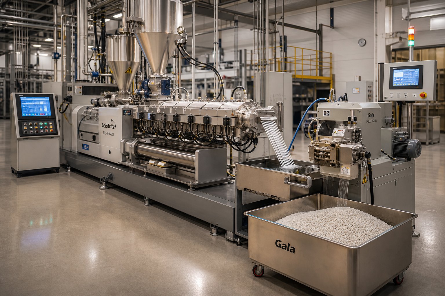
Compounding is where raw polymers become engineered materials. High-speed co-rotating twin screw extruders dominate this space because they deliver the intense dispersive and distributive mixing that masterbatch production, color compounding, filled compounds, and polymer blends demand. Imagine blending 40% glass fiber into a polyamide matrix—you need enough shear to wet out every fiber bundle without breaking fibers down to useless dust. A plastic twin screw extruder configured with carefully staged kneading blocks achieves that balance.
Additive loading in modern compounding can exceed 80% by weight for mineral-filled concentrates, pushing the extruder's torque, wear resistance, and feeding systems to their limits. For masterbatch and color concentrate production, a twin screw plastic extruder typically operates at L/D ratios of 32:1 to 48:1, providing enough barrel length for multiple feeding points, intensive mixing zones, and vacuum venting before the melt reaches the die.
At the line's discharge end, a screw extruder granulator—usually a strand pelletizer or underwater die-face cutter—transforms the compounded melt into uniform pellets ready for downstream forming operations. The pelletizing method itself influences screw design: underwater pelletizing systems require higher, more consistent die pressure than strand pelletizers, which means the pressure-building zone of the screw profile must be tuned accordingly.
Pipe, Profile, Film, and Sheet Production
Forming operations flip the priority from mixing to melt consistency. When the goal is a seamless PVC pipe, a window profile with tight dimensional tolerances, or a cast polyester film, what matters most is delivering a thermally homogeneous melt at rock-steady pressure to the die.
Single screw machines and counter-rotating conical twin screw extruders dominate pipe and profile lines. Their lower shear intensity protects heat-sensitive PVC formulations, while their inherent pressure-generating capability maintains the stable flow that dimensional accuracy requires. A screw plastic extruder running PE pipe, for instance, typically uses an L/D of 24:1 to 30:1 with a compression ratio matched to the resin's bulk density—enough processing length for complete melting and homogenization without the excessive residence time that could degrade the polymer.
Film and sheet extrusion places additional demands on melt uniformity. Even minor temperature gradients across the die width translate into thickness variations visible in the finished product. For specialty films—including polyester extruder applications producing PET sheets for thermoforming—screw designs often incorporate barrier flights or mixing sections near the metering zone to eliminate the last traces of thermal inhomogeneity before the melt enters a flat die or blown-film annular die.
Pharmaceutical and Specialty Applications
Twin screw extruder plastic processing is well established, but the same technology is rapidly expanding into less obvious industries. In pharmaceutical continuous manufacturing, hot-melt extrusion uses co-rotating twin screws to intimately blend active pharmaceutical ingredients (APIs) with polymer carriers, creating amorphous solid dispersions that dramatically improve drug bioavailability. Leistritz, for example, manufactures dedicated pharma-grade twin screw extruders designed with GMP compliance, clean-in-place capability, and process analytical technology (PAT) integration.
Food processing relies on similar principles—twin screw systems texturize vegetable proteins, cook and shape snack products, and encapsulate flavors under precisely controlled thermal and mechanical conditions. Recycling operations present yet another challenge: contaminated, inconsistent post-consumer feedstock that varies in bulk density, moisture content, and melt viscosity from batch to batch. Robust screw and barrel systems with aggressive venting, filtration, and wear-resistant metallurgy are essential to turning waste streams back into usable pellets.
The table below maps each major application against the extruder type, L/D range, and processing priority that typically delivers the best results.
| Application | Recommended Extruder Type | Typical L/D Range | Key Processing Priority |
|---|---|---|---|
| Compounding | Co-rotating twin screw | 32:1–48:1 | Dispersive/distributive mixing, high throughput |
| Masterbatch/Color | Co-rotating twin screw | 32:1–44:1 | Color dispersion uniformity, fast changeover |
| Pipe & Profile | Single screw or conical twin screw | 24:1–33:1 | Melt homogeneity, stable die pressure |
| Film | Single screw (barrier design) | 24:1–30:1 | Thermal uniformity, low gel count |
| Sheet | Single screw or co-rotating twin screw | 24:1–36:1 | Consistent thickness, surface quality |
| Pelletizing | Co-rotating twin screw + pelletizer | 32:1–48:1 | Pellet uniformity, pressure consistency at die face |
| Pharmaceutical (HME) | Co-rotating twin screw (GMP grade) | 25:1–40:1 | API dispersion, residence time control, traceability |
| Recycling | Single screw or co-rotating twin screw | 28:1–44:1 | Devolatilization, contaminant tolerance, filtration |
Notice how the "right" extruder is never universal—it is always defined by what the material needs and what the product demands. A compounding line optimized for maximum mixing would destroy a heat-sensitive PVC profile. A gentle single screw perfect for PE pipe would leave glass-fiber agglomerates untouched in a reinforced compound.
This application-driven perspective also highlights a practical reality that equipment catalogs rarely discuss: no matter how well-matched the extruder type and screw configuration, every machine eventually wears. Abrasive fillers erode flight tips, corrosive additives attack barrel linings, and the precision tolerances that define product quality gradually open up. Recognizing when that wear crosses from acceptable to problematic—and knowing what to do about it—is the difference between proactive maintenance and costly unplanned downtime.
Maintenance, Wear Indicators, and Screw Barrel Replacement
A screw extruder does not fail all at once. It fails gradually—a few microns of metal lost per operating hour, a slowly widening gap between flight tip and barrel wall, a melt temperature that creeps upward so incrementally that operators adjust their setpoints without questioning why. By the time product quality visibly suffers or output drops enough to trigger a production meeting, the damage has been compounding for weeks or months. Recognizing wear patterns early, understanding what drives them, and knowing when to repair versus replace are skills that separate reactive maintenance teams from proactive ones.
Common Wear Patterns in Screws and Barrels
Every operating extruder experiences wear. The question is not whether it is happening—it always is—but which mechanism dominates in your specific process. Three primary wear types account for the vast majority of screw and barrel degradation, and each leaves a distinctive signature.
Abrasive wear is the most common culprit, particularly in screw extruders processing filled compounds. Hard particles—glass fibers, calcium carbonate, talc, titanium dioxide, ceramic microspheres—act as micro-cutting tools as they pass through the screw channel. The sharp machined edges of screw flights and kneading elements gradually become rounded, smooth, and occasionally polished. Abrasive wear accounts for roughly 60 to 70 percent of total wear in filled polymer extrusion, according to ASM International research on wear mechanisms. The rate depends on filler hardness, loading level, and total throughput rather than simple clock hours—a machine running 30 percent glass-filled nylon at high volume wears far faster than one processing unfilled polyethylene at the same speed.
Adhesive wear happens when metal-to-metal contact occurs between the screw and barrel. Picture a cold start: the barrel is empty, the screw is spinning, and no molten polymer cushion exists to keep the rotating flights separated from the barrel wall. The result? Localized welding at microscopic contact points, followed by tearing that leaves score marks on the barrel wall and flattened flight tips. In twin-screw extruders, adhesive wear also appears as scratches on the tips, flanks, and roots of screw flights when the two screws deflect and contact each other—especially at high speeds between production runs when molten resin no longer supports the shafts.
Corrosive wear is the most underestimated threat. When processing PVC, halogenated flame retardants, or fluoropolymers, hydrogen chloride or hydrogen fluoride gas forms at elevated temperatures. These acidic byproducts attack the metal surface, creating a dimpled or pitted appearance. Corrosive wear rates for standard nitrided 4140 steel in rigid PVC service can reach 0.08 to 0.15 mm per 1,000 operating hours—aggressive enough to destroy a screw in a single production season. Even condensation on chilled barrel sections can initiate corrosion in operations that would not otherwise face this problem.
In practice, these mechanisms rarely operate in isolation. A double screw extruder machine compounding glass-filled PVC experiences abrasive and corrosive wear simultaneously, and the synergy between them accelerates damage beyond what either mechanism would cause alone. Identifying the dominant wear driver is essential because the repair strategy—and the replacement material specification—depends entirely on getting that diagnosis right.
Regardless of the mechanism, wear manifests through the same operational symptoms:
- Increased clearance between screw flight outer diameter and barrel bore—the gap that was 0.1 to 0.2 mm when new gradually opens toward 0.5 mm or beyond
- Reduced output at the same screw speed, as widening clearance allows polymer to leak backward past the flights instead of being pumped forward
- Higher melt temperatures, because material slipping over worn flights generates additional shear heat
- Degraded product quality—thickness variations, poor color dispersion, increased gel counts, and surface defects that worsen over time
- Rising specific energy consumption (kWh/kg) as operators increase screw speed to compensate for lost pumping efficiency
When to Repair, Re-coat, or Replace Screw and Barrel Components
Recognizing wear is one thing. Deciding what to do about it is another. The repair-or-replace decision hinges on measurable diagnostic indicators—not guesswork or calendar-based schedules.
Dimensional measurement is the gold standard. During scheduled shutdowns, measure screw flight outer diameter clearance against the barrel bore using a telescoping bore gauge or micrometer. New twin-screw extruders typically have flight-to-barrel clearance of 0.002 to 0.004 inches per side. As predictive maintenance data shows, performance degrades noticeably when clearance reaches 0.010 to 0.012 inches. For screw elements on modular twin-screw extruders, a useful guideline from Xtrutech suggests replacement when diameter loss exceeds approximately 5 percent of the starting dimension over three-quarters of the element length.
Indirect process indicators are equally valuable—especially because they can be monitored continuously without stopping the machine. The following table, adapted from MachineCDN's extrusion monitoring research, summarizes the key metrics and their thresholds:
| Indicator | New / Baseline Condition | Marginal (Monitor Closely) | Replace |
|---|---|---|---|
| Output at rated RPM | 100% of baseline | 85-95% of baseline | Below 85% |
| Melt temp vs. barrel setpoint | Within +/-5 degrees F | +8 to +15 degrees F above setpoint | More than +15 degrees F above |
| Motor amps at rated RPM | Baseline value | +5 to +10% above baseline | More than +10% above baseline |
| Specific energy (kWh/kg) | Baseline value | Within +/-10% of baseline | More than +/-15% deviation |
| Flight clearance | 0.002-0.004 inches | 0.006-0.010 inches | Greater than 0.010 inches |
Tracking these parameters over time builds a wear curve specific to your screw, barrel, and material combination. After two or three replacement cycles with consistent data, you can predict the next replacement window within weeks—transforming an emergency repair into a planned maintenance event.
Here are the warning signs that should trigger an immediate inspection of your screw and barrel components:
- Output drops more than 5 percent at constant screw speed without any change in material or recipe
- Melt temperature consistently exceeds barrel zone setpoints by a widening margin
- Motor amperage at constant RPM trends upward over weeks or months
- Product dimensional variation increases—wall thickness oscillation on pipe, gauge bands on film, weight inconsistency on pellets
- Visual inspection reveals rounded or polished flight edges, scoring on barrel walls, or pitting from corrosive attack
- Operators have incrementally increased screw RPM by 15 to 20 percent to maintain historical output rates
- Specific energy consumption per kilogram of output deviates more than 10 percent from the post-installation baseline
When wear is caught early, you have options beyond outright replacement. Hard-facing with Stellite or tungsten carbide overlays can restore worn flight surfaces to near-original dimensions and dramatically extend service life—particularly valuable for large, expensive screws where full replacement runs into tens of thousands of dollars. Nitriding hardens the surface of new or refurbished screws to improve abrasion resistance, though the hardened case is shallow (0.3 to 0.7 mm) and wears through relatively quickly in severely abrasive service. Bimetallic barrel liners—centrifugally cast wear-resistant alloys bonded inside a steel shell—are the standard for barrels processing filled or corrosive compounds. Refurbishment cost typically runs 40 to 60 percent of a new assembly and restores 85 to 95 percent of original service life, making it a compelling option when the base material remains structurally sound. However, if magnetic particle inspection reveals fatigue cracking or the screw root diameter has worn significantly, replacement is the safer path.
Sourcing Custom and Replacement Screw Barrel Components
The best wear diagnosis in the world means little if the replacement parts themselves are poorly manufactured or mismatched to your process. Whether you are maintaining a single screw pipe line, a twin screw extruder machine for compounding, or a conical twin screw system for PVC profiles, the sourcing decision directly affects how long the next set of components will last—and how much unplanned downtime you will face in the interim.
When evaluating suppliers, consider three practical strategies. First, check whether the manufacturer controls critical production steps in-house—casting, heat treatment, hardfacing, and final grinding—rather than outsourcing them. Vertical integration reduces the metallurgical variability that shows up as inconsistent field life. Second, demand material certifications (EN 10204 3.1 minimum) and hardness documentation for every component. Third, confirm that the supplier has genuine application engineering experience across your specific extrusion line type, not just catalog dimensions.
OEM replacement parts are the default choice for many operations, but aftermarket specialists often deliver equivalent or superior metallurgy at competitive lead times—especially for twin-screw extruders where modular screw elements and barrel segments are standardized across platforms from major twin screw extruder manufacturers. For operations running pipe, profile, film, sheet, or pelletizing lines that need custom or replacement screw barrel support, specialists like NANHAIYA serve as a resource for sourcing components matched to diverse extrusion applications. Building relationships with both your OEM and one or more qualified aftermarket partners gives you sourcing flexibility—critical when a twin-screw extruder machine goes down and lead times from the original manufacturer stretch into months.
The smartest maintenance programs treat screw and barrel replacement not as an emergency expense but as a predictable operating cost. Document every inspection, track wear trends against throughput, and order replacement components before the old ones force a shutdown. That discipline—more than any single alloy or coating choice—is what keeps twin-screw extruders and single screw lines running profitably year after year.
Proactive maintenance protects your existing equipment. But what happens when the wear data, production demands, or a new product line tells you it is time to invest in a different machine altogether? Selecting the right extruder from the ground up requires a structured decision framework—one that starts with your end product and works backward to the equipment specification.
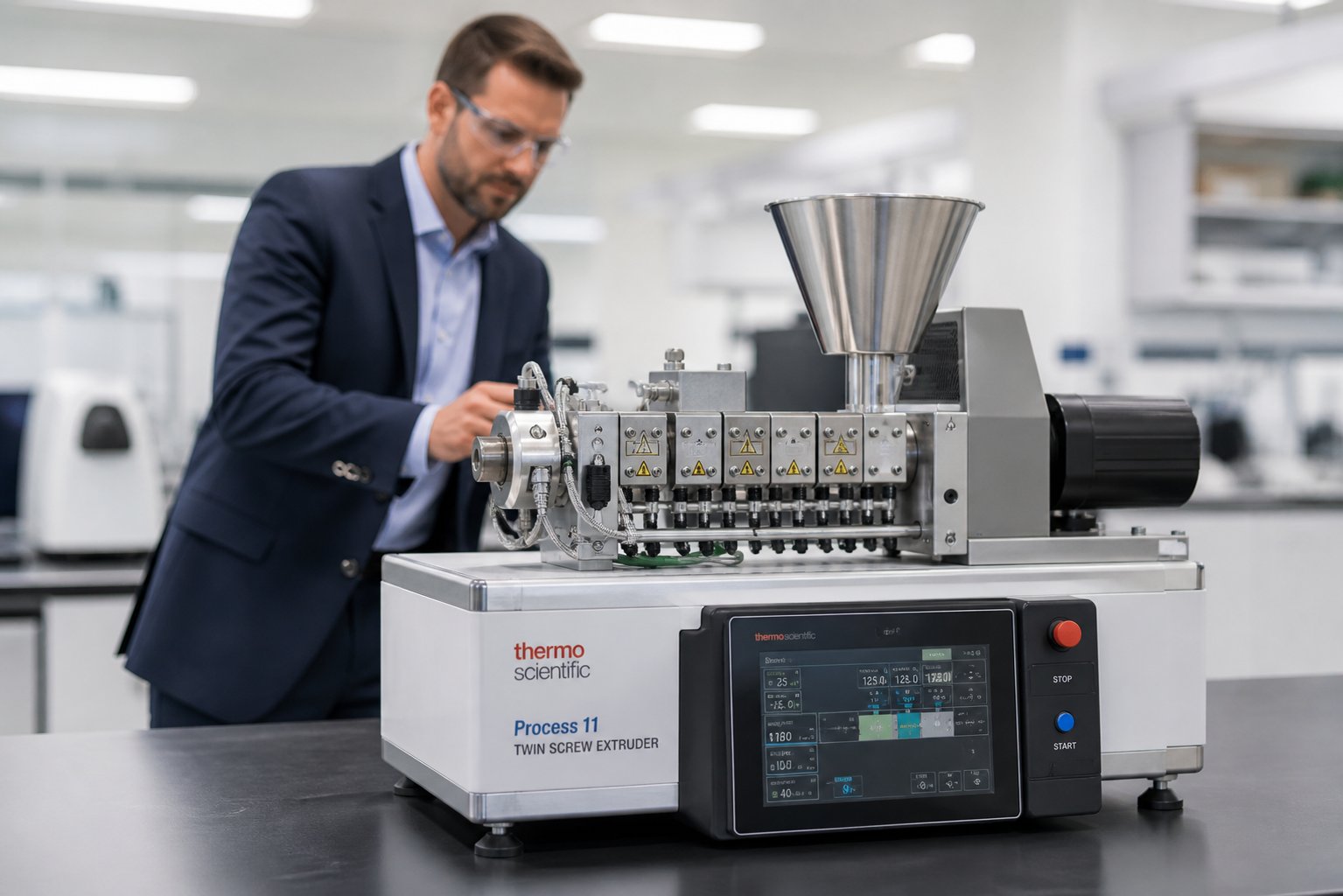
How to Select the Right Screw Extruder for Your Operation
Replacing worn components keeps a production line alive. Choosing the wrong machine in the first place, however, creates problems that no amount of maintenance can fix. You end up fighting the equipment instead of running product—overpaying for mixing capability you never use, or struggling with inadequate dispersion because the architecture simply cannot deliver what your formulation demands.
A structured selection process eliminates that risk. Instead of starting with equipment catalogs and comparing spec sheets, start with your product and work backward through material, process, and budget constraints until the right machine reveals itself.
Matching Extruder Type to Your Material and Product
Think of the selection process as a decision tree with three branching levels: end product, material characteristics, and mixing requirements.
Start with the end product. Are you producing pipe, profile, film, sheet, pellets, or a compounded concentrate? Each product category narrows the field immediately. Pipe and profile operations favor single screw or conical twin screw machines because they prioritize melt homogeneity and stable die pressure over mixing intensity. Film and sheet lines typically run on single screw extruders with barrier screw designs optimized for thermal uniformity. Compounding and pelletizing demand co-rotating twin screw systems for their superior mixing and modular flexibility.
Next, consider the material. Is the feedstock a pre-compounded virgin pellet, a recycled flake with variable bulk density, a powder dry-blend, or a reactive system requiring in-situ chemistry? This is often the decisive fork in the road. As Jinxin Extruder's selection guide emphasizes, the common mistake is treating twin screw as inherently "better" and single screw as "basic." In practice, a stable pellet running through a well-designed single screw machine produces better results at lower cost than the same pellet running through an oversized twin screw extruder that adds complexity without solving a real processing problem.
Finally, assess mixing demand. If the extruder itself must combine base resin with fillers, pigments, stabilizers, or modifiers, you need a machine architecture that can generate sufficient dispersive and distributive mixing. If the material arrives pre-compounded, the extruder's job is melting and pressure generation—not blending. Misidentifying this requirement is the single most expensive specification error in extruder procurement.
Evaluating Throughput, Quality, and Budget Requirements
Once the extruder type is clear, three practical constraints shape the final specification: how much product you need, how good it must be, and what you can afford.
Throughput targets determine screw diameter, motor power, and gearbox torque rating. A 500 kg/h compounding line requires a fundamentally different machine than a 50 kg/h specialty formulation line—even if both use co-rotating twin screws. Oversizing the extruder wastes capital and energy. Undersizing creates a bottleneck that forces operators to push speeds and temperatures beyond optimal ranges, accelerating wear and degrading quality.
Quality specifications add another filter. If your customer requires filler dispersion below 20 microns, you need enough L/D and mixing zone length to achieve that target consistently—not just on a lab sample, but at full production rate. Thermally sensitive formulations like PVC or certain engineering polymers may require counter-rotating designs or carefully profiled co-rotating screws to stay within the safe processing window. Gel count limits for optical film applications, for instance, demand a level of melt homogeneity that rules out simpler screw configurations.
Budget realities force trade-offs. A twin screw extruder price can range from under $50,000 for a small laboratory extruder to well over $1 million for a high-torque production compounder, and the total investment includes feeders, die tooling, downstream equipment, installation, and training. Do not compare machine price alone—factor in maintenance complexity, spare parts cost, energy consumption, and operator skill requirements. A lower-cost machine that demands constant troubleshooting and frequent screw replacement may cost more per kilogram of sellable product than a premium platform with longer service intervals.
One often-overlooked step: validate before you commit. A laboratory twin screw extruder or benchtop twin screw extruder lets you test formulations, optimize screw profiles, and confirm process feasibility at a fraction of production-scale cost. Equipment like Anton Paar's Brabender TwinLab B-TSE-S 30/40—a pilot-scale co-rotating twin screw system with throughput up to 100 kg/h—bridges the gap between lab and factory by providing production-relevant data at small-batch scale. Running trials on a lab scale twin screw extruder before signing a purchase order for a full production line can prevent six-figure specification mistakes. If a laboratory scale extruder reveals that your formulation needs a longer L/D or an additional venting zone, that insight costs thousands in trial material rather than hundreds of thousands in machine modifications after delivery.
Working with Manufacturers and Support Partners
Selecting the right machine is only the beginning. The relationship with your equipment supplier—and your screw barrel support partners—extends across the entire service life of the line.
When evaluating a twin screw extruder for sale, look beyond the machine specifications. Ask about application engineering support: will the manufacturer help you develop the screw profile for your specific formulation, or simply ship a general-purpose configuration and wish you luck? Request references from operations running similar materials and products. Confirm spare parts availability and typical lead times—because when a kneading block or barrel segment wears out, every day waiting for a replacement is a day of lost production.
Equipment decisions extend beyond the initial purchase to ongoing screw barrel support and replacement. As the previous section made clear, screws and barrels are consumable components that require periodic refurbishment or replacement regardless of how well the machine was specified. Building relationships with both your OEM and qualified aftermarket specialists ensures you have sourcing flexibility when lead times tighten. For operations running diverse extrusion line types—pipe, profile, film, sheet, or pelletizing—partners like NANHAIYA provide custom screw barrel solutions tailored to specific machine platforms and processing demands, complementing OEM channels with specialized metallurgical expertise and application-specific engineering.
Here is a practical framework that organizes the entire selection process from initial concept through supplier evaluation:
- Define the application: Specify the end product (pipe, profile, film, sheet, pellet, compound), target dimensions, and quality requirements.
- Characterize the material: Document the feedstock form (pellet, powder, flake, liquid), polymer type, filler content, additive package, and any thermal or shear sensitivity constraints.
- Determine mixing requirements: Decide whether the extruder must compound, blend, or react—or simply melt and convey pre-compounded material.
- Select the extruder architecture: Match single screw, co-rotating twin screw, counter-rotating twin screw, or conical twin screw to the material and product requirements identified above.
- Specify throughput and L/D: Size the screw diameter, motor power, and barrel length to meet production volume targets with headroom for future growth.
- Validate at lab or pilot scale: Run formulation trials on a lab scale extruder or pilot machine to confirm process feasibility, optimize screw profile, and generate baseline SME data before committing to production equipment.
- Evaluate total cost of ownership: Compare capital cost, energy consumption, maintenance burden, spare parts pricing, and expected screw and barrel replacement intervals across shortlisted suppliers.
- Assess supplier capability: Confirm application engineering support, reference installations, training programs, and spare parts lead times.
- Establish screw barrel support partnerships: Identify both OEM and aftermarket sources for replacement screws, barrels, and modular elements to ensure sourcing resilience across the machine's operating life.
- Commission and baseline: Document startup process parameters—output rate, melt temperature, motor load, specific energy—as the reference baseline for all future wear monitoring and maintenance planning.
Notice that the last step circles back to maintenance—the topic covered in the previous section. That is intentional. Selection, commissioning, operation, and maintenance are not separate activities. They form a continuous loop: the data you collect during commissioning feeds your maintenance program, and the wear patterns you observe during maintenance inform your next equipment specification. Operations that treat this loop as a system—rather than a series of disconnected decisions—consistently achieve higher uptime, lower cost per kilogram, and longer equipment service life.
Whether you are specifying your first production extruder, scaling up from a benchtop twin screw extruder to a full manufacturing line, or replacing an aging machine that has reached the end of its service life, the framework remains the same. Start with the product, work backward to the process, size the equipment to the demand, validate before you invest, and build the supplier relationships that keep the line running long after the purchase order is signed.
Frequently Asked Questions About Screw Extruders
1. What is the difference between a single screw extruder and a twin screw extruder?
A single screw extruder uses one rotating screw inside a cylindrical barrel and excels at melting and conveying pre-compounded materials for pipe, film, and sheet production. It offers lower cost and simpler maintenance. A twin screw extruder uses two intermeshing screws in a figure-eight barrel bore, delivering superior dispersive and distributive mixing for compounding, reactive extrusion, and formulations with high filler loadings. Co-rotating twin screws provide self-wiping action and modular flexibility, while counter-rotating designs offer gentler shear suited for heat-sensitive materials like PVC. The choice depends on whether your process prioritizes mixing intensity or straightforward melt conveying and pressure generation.
2. What does the L/D ratio mean on a screw extruder and why does it matter?
The L/D ratio is the flighted screw length divided by its outer diameter. It determines how much processing runway the material has before exiting the die. Single screw extruders typically use L/D ratios of 20:1 to 36:1, while twin screw compounding machines range from 32:1 to 48:1. A higher L/D provides more residence time, more heat transfer surface, and room for additional mixing or devolatilization stages. However, excessively long L/D increases energy consumption, raises the risk of polymer degradation from extended heat exposure, and heightens shaft deflection concerns. The optimal ratio depends on the specific polymer, filler content, and processing goals of your application.
3. How do I know when my extruder screw and barrel need replacement?
Key warning signs include a drop in output greater than 5% at constant screw speed, melt temperatures consistently exceeding barrel setpoints by a widening margin, rising motor amperage over weeks or months, increasing product dimensional variation, and visible wear such as rounded flight edges or barrel wall scoring. Dimensional measurement during shutdowns is the most reliable diagnostic: performance typically degrades noticeably when flight-to-barrel clearance exceeds 0.010 inches. Tracking specific energy consumption (kWh/kg) against a post-installation baseline also reveals gradual efficiency loss. Early detection allows cost-effective options like hard-facing or re-nitriding rather than full component replacement.
4. What are kneading blocks in a twin screw extruder and how do stagger angles affect mixing?
Kneading blocks are modular disc-shaped screw elements staggered at specific angular offsets along a short segment. They provide the primary mixing capability in co-rotating twin screw extruders. The stagger angle controls the balance between mixing intensity and forward conveying: 30-degree blocks offer moderate mixing with maintained conveying, 60-degree blocks deliver very high dispersive mixing with reduced conveying, and 90-degree neutral blocks provide maximum shear with no forward push. Wider kneading discs promote dispersive mixing by applying stronger shear stress, while narrower discs favor distributive mixing by splitting and recombining the melt with less particle size reduction. Engineers arrange these elements strategically to match specific compounding, blending, or reactive processing requirements.
5. How do I select the right screw extruder for my manufacturing application?
Start with your end product—pipe, profile, film, sheet, pellet, or compound—then work backward through material characteristics and mixing requirements. If the feedstock is pre-compounded and needs only melting and conveying, a single screw extruder is typically the most cost-effective choice. If the extruder must blend fillers, pigments, or reactive components, a co-rotating twin screw offers the necessary mixing intensity. Counter-rotating or conical twin screw designs suit heat-sensitive materials like PVC. Size the machine to throughput targets with growth headroom, validate formulations on a laboratory or pilot-scale extruder before committing to production equipment, and evaluate total cost of ownership including energy, maintenance, and screw barrel replacement intervals rather than purchase price alone.
Written by
Nanhaiya Technical Team
Zhoushan Nanhaiya Plastic Machinery Co., Ltd.
The Nanhaiya technical team supports screw and barrel manufacturing projects through application review, technical communication, custom manufacturing coordination, and production and quality control.
Discuss Your Application
Related Articles
More insights on screw barrel technology and plastics processing.

What Nobody Tells You About Screw Barrel For Plastic Machine Design
Oct 10, 2026
Learn how screw barrel for plastic machine design affects melt quality, throughput, and wear life. Covers geometry, resin matching, troubleshooting, and sourcing.
Read Article
Single Screw Extruder for Sheet: Stop Guessing, Start Specifying
Oct 9, 2026
Learn how to specify a single screw extruder for sheet production. Covers screw geometry, resin-specific processing, troubleshooting, and maintenance best practices.
Read Article
PE Pipe Extruder Machine: What Datasheets Won't Tell You
Oct 9, 2026
Learn how a PE pipe extruder machine works, key specs explained, material grade selection, maintenance tips, and buyer guidance beyond the datasheet.
Read ArticleLooking for something else?
Search by material, symptom or product and jump straight to the relevant page.
These are navigation suggestions based on keyword matching — not a quotation, not a delivery commitment, and not a substitute for engineering review. Final specification is confirmed by our engineers against your drawings and processed material.
Need help with screw barrel selection?
Share your machine model, processed material and application. Our team can help with pricing and technical support.