

What Are Screw Elements and Why Do They Matter
Imagine building a processing line where every function - conveying, melting, mixing, venting, and pressure generation - depends on which pieces you slide onto a single pair of shafts. That is exactly what screw elements do inside a twin screw extruder, and choosing the wrong configuration can silently cost you throughput, product quality, and profit.
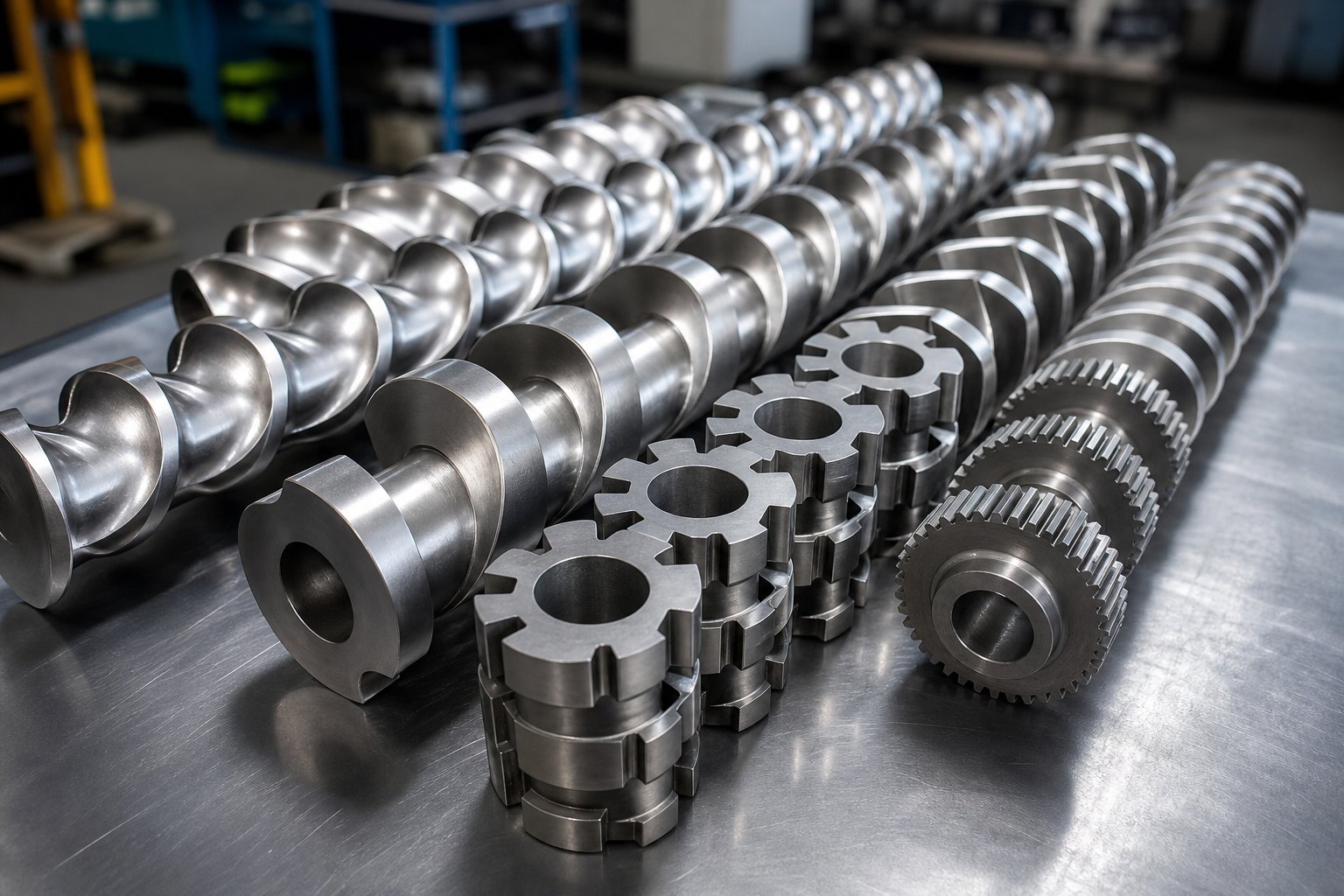
Screw elements in a twin screw extruder are modular, interchangeable components mounted onto splined shafts. Each element is engineered to perform a specific processing function - conveying, melting, mixing, venting, or pressure build-up - and can be rearranged, swapped, or replaced to tailor the extruder to virtually any material or application.
Defining Screw Elements in Modular Extrusion
Twin screw extruder screw elements are identified by their diameter, pitch, flight thickness, and channel depth. As NC State Extension explains, these elements are assembled on the screw shaft, and the shaft size is dictated by the extruder's scale. Different pitches, depths, and shapes allow each segment to handle a distinct task - from gently moving raw pellets forward to applying intense shear that breaks down agglomerates in a filled compound.
Why Modularity Changes the Engineering Equation
A conventional single-screw extruder uses a monolithic screw machined from one piece of steel. You get one fixed geometry. If your process changes, you order an entirely new screw. Twin screw extruder elements, by contrast, slide on and off splined shafts like beads on a rail. Need more shear in the melting zone? Swap in aggressive kneading blocks. Processing a heat-sensitive resin that degrades under excess energy? Replace those blocks with gentler conveying segments. This modularity turns the screw profile into a tunable instrument rather than a static tool - and it is the reason element selection sits at the center of every twin screw extrusion engineering decision.
Co-Rotating vs Counter-Rotating Element Considerations
Not all twin screw extruder elements are interchangeable across machine types. Co-rotating extruders use self-wiping, intermeshing geometry - known as Erdmenger profiles - where both screws turn in the same direction and continuously wipe each other's surfaces. Counter-rotating machines, on the other hand, mesh with a calendering action that creates enclosed C-shaped chambers for positive pumping. Element geometry, stagger angles, and even material grades differ between these two architectures. Many suppliers gloss over this distinction, offering generic element recommendations that ignore whether you're running a co-rotating compounder or a counter-rotating profile line.
Understanding the broad categories of these modular components - and the parameters that make each one unique - is what separates a well-optimized screw profile from a costly guess.
The Three Foundational Screw Element Categories Explained
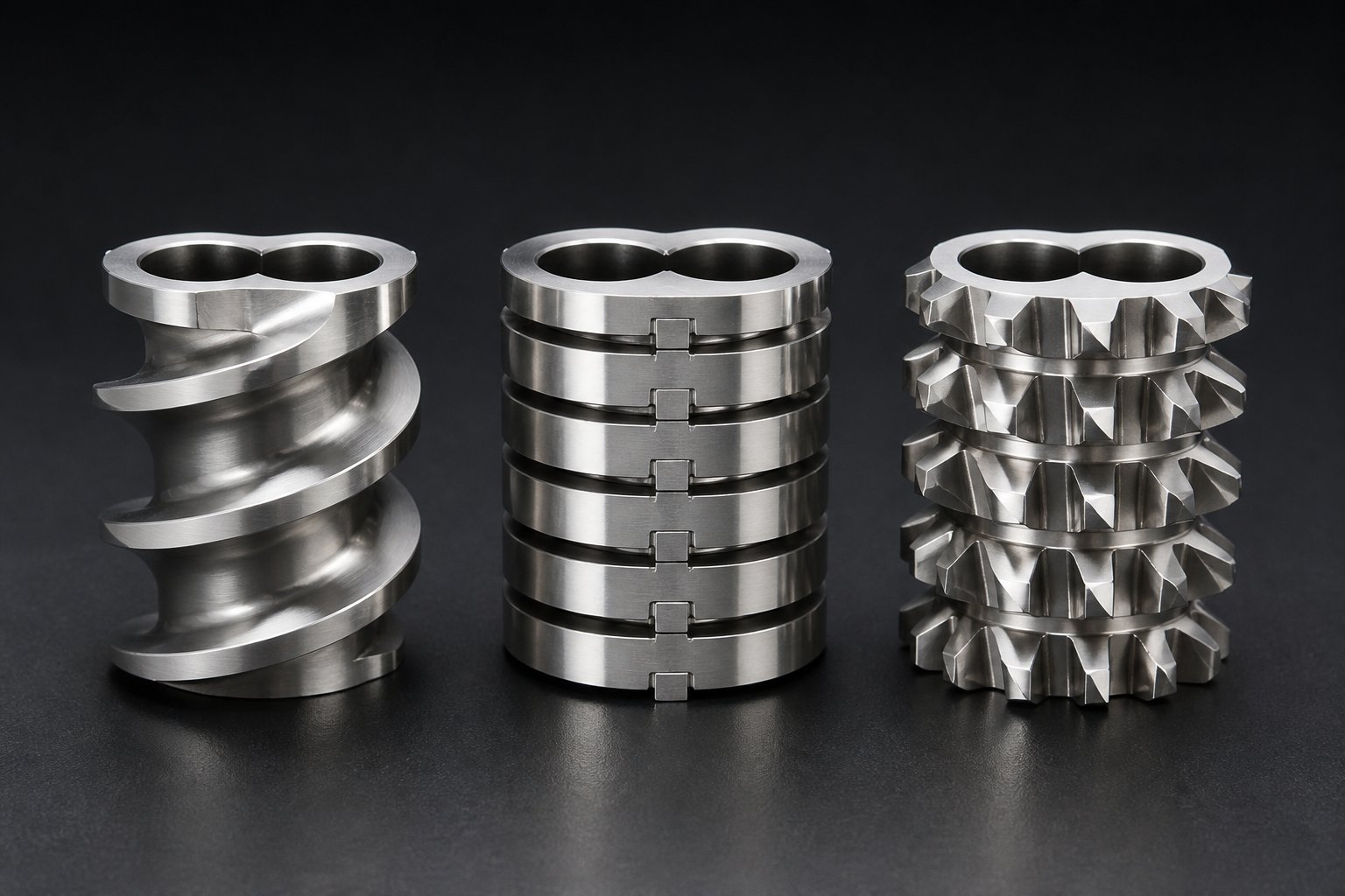
Every twin screw extruder screw element you will ever encounter falls into one of three foundational families: conveying elements, kneading blocks, or mixing elements. Each family handles a different part of the processing puzzle, and the geometric parameters within each family determine how aggressively - or gently - that job gets done. Grasping these three categories is the fastest path to reading any screw profile like an open book.
Conveying Elements and Pitch Geometry
Twin screw extruder conveying elements are the workhorses that move material from the feed throat toward the die. They look like helical flights wrapped around the shaft bore, and their behavior is governed by three key variables: pitch direction, pitch length, and the number of flight tips (also called thread starts).
Pitch direction is the most binary choice. Forward-pitch elements push material toward the discharge end. Reverse-pitch elements do the opposite - they push material backward, acting as restrictive dams that increase fill level, residence time, and local pressure upstream. Engineers place reverse elements strategically before vent ports or after kneading zones to create melt seals and intensify mixing upstream.
Pitch length controls how quickly the material travels. Imagine a staircase: a large pitch is like taking the stairs two at a time - fast movement, low fill, maximum free volume. A small pitch is like short, deliberate steps - slower conveying, higher fill, and greater pressure build-up. In practical terms, large-pitch elements (roughly 1.5 to 2 times the screw diameter) dominate the feed zone and vent zones where open volume matters, while small-pitch elements (around 0.25 to 0.75 times the diameter) sit near the die to pump melt against back pressure.
Thread starts add another layer of control. Single-flighted elements offer wide channels and maximum suction, making them ideal for starve-fed intake. Double-flighted designs are the standard for most conveying tasks. Triple-flighted elements have shallow channels and generate the highest shear of any conveying geometry, so they sometimes appear in melting transitions where extra energy input is helpful.
Kneading Blocks and Stagger Angle Effects
If conveying elements are the highway, kneading blocks are the intersections where real transformation happens. Each kneading block consists of a series of lobe-shaped discs stacked along the shaft, and the way those discs are arranged determines everything from gentle blending to aggressive dispersion.
Four geometric parameters define a kneading block's personality:
- Stagger angle - the angular offset between consecutive discs. A 30-degree stagger maintains strong forward conveying with mild mixing. A 45-degree angle increases mixing while reducing conveying. A 60-degree offset delivers strong shear with minimal forward push. And a 90-degree (neutral) kneading block has zero conveying ability, creating 100% fill and the most intense mixing possible.
- Disc count - more discs in a given length mean more shearing events per unit of barrel length. A five-disc block packs more mixing action into the same space than a three-disc block.
- Disc width - wider discs (full-width, often designated KBW) generate stronger dispersive shear because they expose material to longer tip-to-wall contact. Narrower discs (half-width, often designated KP) favor distributive spreading with less energy input.
- Advance direction - forward-staggered blocks convey material downstream while mixing. Reverse-staggered blocks push material backward, maximizing restriction and shear. Neutral blocks simply hold material in place, forcing it to endure repeated kneading cycles.
You'll notice that every parameter involves a trade-off between mixing intensity and material residence time. Cranking up the stagger angle or switching to wider discs boosts shear, but it also raises melt temperature and can degrade heat-sensitive polymers. That balance is exactly why kneading block selection is often the most debated decision in profile design.
Mixing Elements and Their Hybrid Role
Twin screw extruder mixing elements occupy a unique middle ground. Unlike kneading blocks - which rely on disc-to-disc shearing - mixing elements use features like grooves, teeth, or slotted flights to split, recombine, and redistribute melt streams. This makes them especially effective at distributive mixing: spreading minor components (pigments, additives, low-concentration fillers) evenly throughout the melt without hammering the material with excessive shear.
Toothed mixing elements are a common example. As documented by NC State Extension, these elements convey forward while mixing ingredients evenly, and they are frequently placed before the compression zone to blend solid and liquid streams. Their shear effect is near zero compared to kneading blocks, yet their distributive mixing capability is significant.
Some mixing element designs intentionally combine distributive and dispersive functions within a single piece. They achieve this by alternating open-channel sections (distributive) with tight-clearance tips (dispersive), giving engineers a way to accomplish both mixing types without stacking multiple element families back to back. This hybrid capability is particularly valuable in space-constrained profiles or when processing formulations that need uniform color dispersion alongside filler deagglomeration.
The table below consolidates every foundational category, its defining parameters, its primary processing role, and where you will typically find it along the barrel. This single view is designed to serve as a quick-reference guide when you are reading - or building - a screw profile.
| Element Category | Key Geometric Parameters | Primary Function | Typical Zone Placement |
|---|---|---|---|
| Forward Conveying Elements | Pitch length (large to small), number of flight tips (1, 2, or 3), flight depth | Transport material downstream; control fill level, residence time, and pressure build-up | Feed zone (large pitch), melt conveying between functional zones (medium pitch), pressure build-up / die discharge zone (small pitch) |
| Reverse Conveying Elements | Reverse pitch direction, short segment length (typically less than 1x screw diameter) | Restrict forward flow, increase upstream fill and pressure, create melt seals for venting | Immediately before vent ports; after kneading sections to intensify upstream shear |
| Kneading Blocks (Forward) | Stagger angle (30°, 45°, 60°), disc count, disc width (KP half-width / KBW full-width) | Melting, dispersive and distributive mixing with forward material advance | Plastication / melting zone; primary mixing zone |
| Kneading Blocks (Neutral, 90°) | 90° stagger angle, disc count, disc width | Maximum shear and mixing intensity with zero conveying; 100% barrel fill | High-intensity mixing zone; end of kneading sequence for full melt homogenization |
| Kneading Blocks (Reverse) | Reverse stagger direction, disc count, disc width | Push material backward, creating maximum restriction and dispersive shear | End of kneading sequence for melt seal; before vacuum vent zones |
| Mixing Elements (e.g., Toothed) | Number of teeth, number of tooth rows, segment length | Distributive mixing with gentle or zero dispersive shear; forward conveying maintained | Before compression zone; after primary kneading to homogenize without added shear |
These three element families cover the vast majority of standard screw profiles. Yet certain applications - reactive extrusion, temperature-sensitive biopolymers, high-filler-loading compounds - push beyond what conveying elements, kneading blocks, and basic mixing elements can achieve on their own. That is where a less-discussed category of specialized elements enters the picture.
Specialized Screw Elements Beyond the Basic Three
Conveying elements, kneading blocks, and standard mixing elements handle the bulk of everyday compounding work. But what happens when you are processing a heat-sensitive biopolymer that degrades under kneading-block shear, or need a gas-tight melt seal upstream of a vacuum port without choking throughput? That is where specialized twin screw extruder element designs earn their place on the shaft - and where most supplier catalogs go frustratingly quiet.
Gear and Toothed Mixing Elements for Advanced Configurations
Gear mixing elements - often labeled TME (toothed mixing element) or ZME (Zahnmischelement) depending on the manufacturer - represent one of the most significant departures from the classic Erdmenger self-wiping profile. Instead of continuous helical flights, these elements feature rows of intermeshing teeth that repeatedly split, redirect, and recombine melt streams as material passes through. The result is outstanding distributive mixing with dramatically lower shear stress than kneading blocks of comparable length.
How significant is the difference? 3D CFD simulations with particle tracking conducted at Paderborn University showed that the ZME achieved the best distributive mixing index (MQ) of all elements tested - outperforming 90-degree kneading blocks and conveying elements alike. At 400 rpm, the ZME reached an MQ value of approximately 0.9, while a short kneading block (KB12) could only manage around 1.34 under identical conditions. In dispersive mixing, the ZME also stood out: it exposed particles to a broader and more uniform range of high shear stresses, generating a flat plateau in the frequency distribution rather than the sharp, narrow peak typical of kneading blocks. This means a ZME simultaneously distributes minor components evenly and breaks down agglomerates more consistently.
Toothed elements are particularly valuable in twin screw extruder TSE series screw element configurations designed for temperature-sensitive materials. Because their open tooth geometry allows frequent melt-stream splitting without prolonged high-shear contact, they add far less frictional heat than kneading blocks. Imagine compounding a color masterbatch with an organic pigment that discolors above a narrow thermal window - a toothed element delivers the homogeneity you need without pushing the melt over the edge.
Screw Mixing Elements and Blister Rings
Screw mixing elements (SMEs) take a different design approach. They retain the helical flight geometry of conveying elements but introduce strategically machined slots, grooves, or bypass channels cut into the flights. Material flows forward through the main channel while a portion continuously leaks through these openings, creating gentle folding and recombination. The net effect is mild distributive mixing layered on top of positive conveying - ideal for blending liquid additives into a melt stream or homogenizing color concentrates without disrupting an already-established thermal profile.
Blister rings, by contrast, serve a purely functional rather than mixing-oriented purpose. A blister ring is a cylindrical disc with a tight radial clearance against the barrel wall - typically just a few tenths of a millimeter. It creates a near-complete melt seal across the barrel cross-section, forcing the polymer to squeeze through the narrow annular gap. Engineers place blister rings immediately upstream of atmospheric or vacuum vent ports to prevent gas from traveling backward along the screw channel. Without this seal, volatiles pulled by vacuum would simply migrate upstream rather than exiting through the vent.
Here is a concise breakdown of each specialized twin screw extruder element and its core function:
- Gear / Toothed Mixing Elements (TME / ZME) - Intermeshing tooth rows split and recombine melt streams repeatedly, delivering superior distributive mixing and consistent dispersive stress with significantly less heat generation than kneading blocks.
- Toothed Elements for Sensitive Formulations - Open-channel tooth geometry minimizes residence time under high shear, protecting heat-sensitive or shear-sensitive polymers from degradation while still achieving thorough blending.
- Screw Mixing Elements (SME) - Slotted or grooved flight geometry layered onto a conveying-element base, combining forward transport with gentle distributive mixing for liquid injection zones or low-intensity blending tasks.
- Blister Rings - Tight-clearance cylindrical seals that block gas migration along the screw channel, enabling efficient devolatilization at atmospheric or vacuum vent ports without adding shear or mixing.
When to Deploy Specialized Elements Over Standard Ones
A common mistake is defaulting to kneading blocks for every mixing challenge. Kneading blocks excel at melting and high-shear dispersion, but they are a blunt instrument when the goal is gentle homogenization or melt sealing. Specialized elements exist precisely to handle tasks where standard categories over-deliver on shear or under-deliver on sealing. If your SAM10 screw element layout or similar twin screw extruder element configuration relies exclusively on conveying segments and kneading blocks, you may be leaving performance on the table - or worse, degrading your product by applying more mechanical energy than the formulation can tolerate.
The real engineering question is never just what type of element to use, but how each element's geometry translates into the specific mixing mechanism your formulation demands. That relationship between shape and function - distributive versus dispersive mixing - is where most technical resources fall short.
How Element Geometry Controls Distributive and Dispersive Mixing
You can memorize every screw element category on the market, but if you cannot connect a specific geometry to the mixing mechanism it produces, your screw profile is still a guess. Most technical resources define distributive and dispersive mixing in the abstract and leave engineers to figure out the rest on their own. Here, we close that gap by mapping real element configurations to each mixing type - so every segmented screw element choice on your twin extruder ties directly to a measurable processing outcome.
Understanding Distributive and Dispersive Mixing
Picture a handful of blue pigment granules tossed into a bucket of white polymer pellets. Two separate problems must be solved before the final compound looks uniformly blue.
Distributive mixing is the spatial rearrangement of those pigment particles so they spread evenly throughout the polymer matrix. Think of it as stirring sugar into coffee - you are repositioning particles, not changing their size. In a twin screw extruder, distributive mixing splits and recombines melt streams so that minor components end up uniformly distributed across the entire cross-section. Kenneth Russell of Optimized Compounds illustrates this clearly: a material can be distributed evenly yet still contain large agglomerates, producing a blotchy, non-uniform product.
Dispersive mixing solves the other half of the equation. It applies mechanical stress - shear or elongation - to break down cohesive domains such as agglomerates, liquid droplets, or fiber bundles into their smallest achievable size. Carbon black is a textbook case: individual aggregates are fused together during combustion and then held in loose agglomerates by weak forces. Only dispersive shear can break those agglomerates apart so the black color develops fully and uniformly.
A high-quality compound demands both mechanisms working in sequence. Dispersing particles to their ultimate size is pointless if they remain clustered in one region of the melt. Distributing large agglomerates across the melt simply spreads the problem around without solving it. The challenge is selecting screw elements for a twin screw extruder that deliver exactly the right ratio of each.
Mapping Element Geometry to Mixing Mechanism
So which elements drive which mechanism? The answer lies in disc width, stagger angle, and overall element architecture.
Dispersive mixing demands high shear stress concentrated at element tips. Wide kneading block discs (full-width KBW type) at steep stagger angles - 60 degrees or 90 degrees - force polymer through tight clearances between the disc tip and barrel wall. As the wide disc rotates, it plows through the melt, smearing and compressing the material rather than letting it flow around the edge. Research using 3D CFD flow simulation with particle tracking confirms that higher stagger angles and wider discs shift the shear-stress frequency distribution toward higher values, meaning more particles experience the intense forces needed to rupture agglomerates. Adding a neutral (90-degree) or reverse kneading block at the end of a sequence ensures the mixing section stays highly filled, which makes the shearing action far more efficient than a loosely filled channel.
Distributive mixing relies on melt-stream splitting and recombination rather than brute-force shear. Narrow kneading block discs (half-width KP type) at shallow stagger angles - typically 30 degrees - slice through the polymer in a scissoring action. Material is divided by one disc and folded over by the next, redistributing minor components without generating excessive heat. Gear mixing elements (ZME/TME) take this principle even further: their intermeshing tooth rows continuously split and recombine melt streams, achieving the lowest mixing-quality index (MQ) values recorded in CFD studies - roughly 0.9 at 400 rpm compared to 1.34 for a short kneading block under identical conditions.
Certain configurations achieve both simultaneously. A practical approach is to sequence narrow forward-staggered kneading blocks (distributive) followed by wider blocks at 60 to 90 degrees (dispersive), then cap the section with a neutral or reverse element to maintain barrel fill. This progressive ramp - sometimes called a graduated mixing section - lets the melt experience increasing shear intensity without a sudden thermal spike.
The table below maps each mixing type directly to the twin screw extruder kneading block elements and specialized geometries best suited for it, along with a real-world application where that pairing matters most.
| Mixing Type | Preferred Element | Stagger Angle or Geometry | Application Example |
|---|---|---|---|
| Dispersive | Wide kneading blocks (KBW, full-width discs) | 60° to 90° stagger angle | Breaking down carbon black agglomerates in polyethylene masterbatch |
| Dispersive | Reverse kneading blocks | Reverse stagger direction (any angle) | Deagglomerating mineral fillers (CaCO3, talc) in high-loading PP compounds |
| Distributive | Narrow kneading blocks (KP, half-width discs) | 30° forward stagger angle | Spreading liquid stabilizers or low-concentration additives through a melt |
| Distributive | Gear / toothed mixing elements (ZME / TME) | Intermeshing tooth rows, no stagger angle | Color homogenization in temperature-sensitive biopolymer or PLA compounds |
| Both (sequential) | Graduated kneading block sequence + ZME | 30° → 60° → 90° kneading blocks, followed by ZME | Glass-fiber-reinforced nylon requiring fiber-bundle breakup and even distribution |
| Both (single element) | Screw mixing elements (SME) with slotted flights | Helical flights with bypass channels | Blending recycled flake with virgin resin where gentle dispersion and redistribution are both needed |
Notice a pattern: dispersive mixing screw elements in a twin screw always trade higher shear stress for higher melt temperature. Every degree of additional stagger and every millimeter of extra disc width adds mechanical energy that converts to heat. That is why material selection for the elements themselves becomes the next critical variable - choosing the wrong steel grade in a high-shear, abrasive-filler environment can destroy an element in a fraction of its expected service life.
Screw Element Materials and Metallurgy Selection
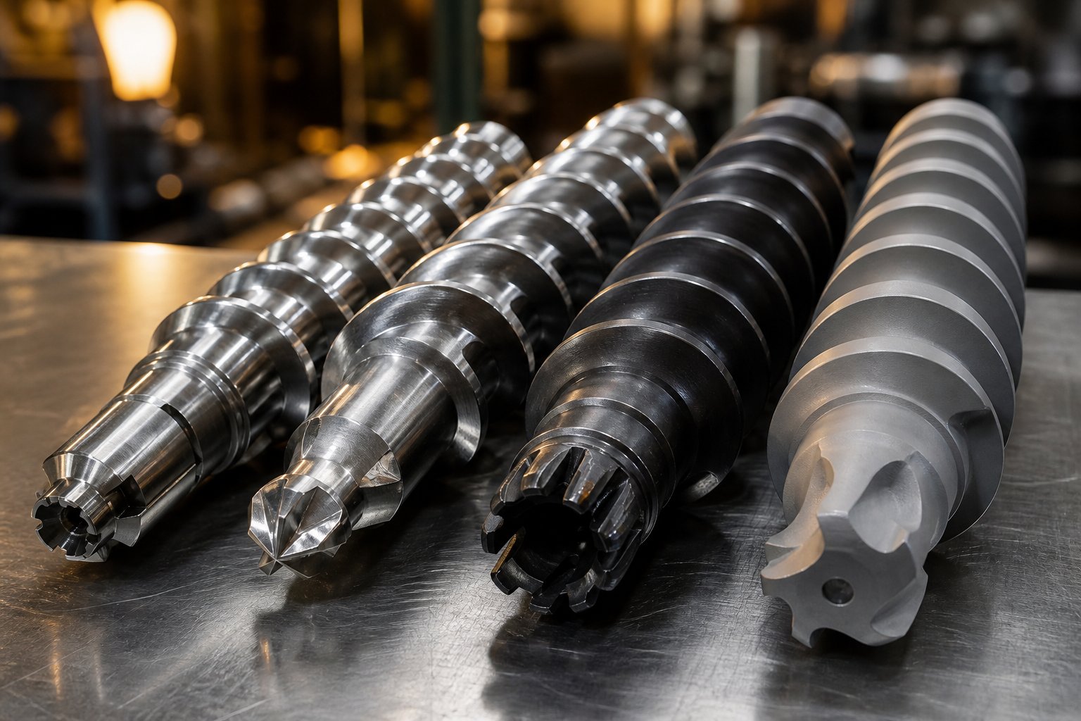
A perfectly designed screw profile means nothing if the elements themselves cannot survive the processing environment. Every plastic twin screw extruder screw element faces a relentless combination of abrasion, corrosion, heat, and mechanical torque - and the steel grade you choose determines whether that element lasts 8,000 hours or 800. Yet most supplier spec sheets list a material name without explaining what it resists, why it costs more, or when a cheaper option is genuinely adequate. Here is what the metallurgy actually involves.
Steel Grades and Surface Treatments for Screw Elements
Twin screw extruder element material choices fall along a clear performance-cost spectrum, from basic nitrided steels to advanced powder metallurgy composites. Each grade trades off hardness, toughness, corrosion resistance, and price.
Nitrided steel (e.g., 38CrMoAlA) is the entry point. The base alloy is placed in an ammonia atmosphere at 500-570 degrees Celsius, allowing nitrogen atoms to diffuse into the surface and form a hard nitride layer - typically reaching 65-72 HRC at the surface with a case depth of 0.3 to 0.6 mm. As KY Extruder's materials guide notes, nitrided steel offers good machinability and lower cost, making it suitable for general compounding where abrasive fillers are absent or present only in low concentrations.
Through-hardened tool steel and high-speed steel (HSS) - such as Cr12MoV or W6Mo5Cr4V2 (the M2 equivalent) - contain elevated levels of carbon, chromium, tungsten, molybdenum, and vanadium. After quenching and tempering, these grades achieve bulk hardness of 58-65 HRC, meaning the entire cross-section resists wear rather than just a thin surface skin. They are the workhorse choice for medium-to-high wear conditions: think calcium carbonate at 40% loading or talc-filled polypropylene.
Powder metallurgy HIP (PM-HIP) steels push the boundary further. Pre-alloyed metal powders are consolidated under hot isostatic pressing, producing an exceptionally uniform carbide distribution that eliminates the segregation found in conventionally cast steels. The result is a screw element for plastic twin screw extruder applications involving heavy glass-fiber reinforcement or aggressive mineral fillers - environments where conventional tool steel wears through in weeks. Grades like CPM 9V or CPM 10V achieve hardness in the 60-64 HRC range with toughness values that conventional steels at the same hardness simply cannot match.
Tungsten carbide composites and high-wear HIP alloys (WR5, WR13, WR14) sit at the top of the spectrum. These materials incorporate ultra-high concentrations of strong carbide-forming elements - vanadium, tungsten - that generate massive volumes of hard carbide particles (such as VC) within the steel matrix. Wear resistance can be five to ten times that of standard HSS, and they survive the most punishing formulations: 60% glass fiber, heavily filled flame-retardant compounds, or recycled streams contaminated with metal fragments.
Beyond base material, surface treatments add another layer of defense:
- Gas nitriding - Diffuses nitrogen into the surface to form a hard case (900-1,200 HV). Most cost-effective for nitriding-grade steels; limited benefit on already-hard tool steels.
- Hard chrome plating - Deposits a corrosion-resistant chromium layer electrochemically. Once widely used, it is declining in high-end applications because the coating can peel under heavy mechanical load and raises environmental concerns during deposition.
- HVOF thermal spray coatings - High-velocity oxy-fuel spraying bonds a dense tungsten carbide or ceramic coating to the element surface. Delivers exceptional abrasion and corrosion resistance, making it a practical alternative to replacing the entire element with a premium base material.
Matching Metallurgy to Processing Environment
Choosing the right twin screw extruder element material is not about picking the hardest grade available - it is about matching the dominant wear or corrosion mechanism in your specific process.
Abrasive fillers like glass fiber, calcium carbonate, and talc cause adhesive and erosive wear at element tips and flight edges. The harder the filler and the higher its loading percentage, the further up the material spectrum you need to move. Standard polyolefin compounding with less than 10% mineral filler may do fine on nitrided 38CrMoAlA. Jump to 30-40% glass fiber in nylon 66, and you are looking at PM-HIP steels or tungsten carbide composites to achieve acceptable element life.
Corrosive polymers demand a completely different approach. PVC releases hydrochloric acid during processing; fluoropolymers generate hydrofluoric acid. Hardness alone will not help - you need nickel-based alloys or high-chromium corrosion-resistant grades that form stable passivation layers against chemical attack. Skipping this step means waking up to pitted, cratered elements after just a few production runs.
Standard unfilled or lightly filled polyolefins are the least demanding environment. Nitrided steel delivers a perfectly adequate service life at the lowest cost tier, and upgrading to tool steel in this scenario adds expense without meaningful return.
| Material Grade | Hardness Range | Best Suited Processing Conditions | Relative Cost Tier |
|---|---|---|---|
| Nitrided Steel (38CrMoAlA) | 65-72 HRC (surface) | Unfilled or lightly filled polyolefins, general-purpose compounding | $ (Low) |
| Tool Steel / HSS (W6Mo5Cr4V2, Cr12MoV) | 58-65 HRC (through-hardened) | Medium filler loading (CaCO3, talc up to 40%), masterbatch, recycled plastics | $$ (Medium) |
| PM-HIP Steel (CPM 9V, CPM 10V) | 60-64 HRC | High glass-fiber loading (30-50%), aggressive mineral fillers, high-output lines | $$$ (High) |
| High-Wear HIP Alloy (WR5, WR13, WR14) | 62-68 HRC | Extreme abrasion: 50-60% glass fiber, metal-contaminated recycle streams, heavy flame retardants | $$$$ (Very High) |
| Nickel-Based Corrosion-Resistant Alloy | 35-45 HRC | PVC, fluoropolymers, reactive extrusion with corrosive by-products | $$$$ (Very High) |
| HVOF-Coated Element (any base) | 1,000-1,400 HV (coating) | Retrofit upgrade for abrasive or corrosive conditions without changing base geometry | $$-$$$$ (varies with base) |
Understanding OD to ID Ratio and Torque Implications
You will see the OD/ID ratio - also written as Do/Di - listed on nearly every extruder datasheet, yet few sources explain what it actually controls. The outer diameter (Do) is the tip-to-tip measurement of the screw element. The inner diameter (Di) is the bore diameter that mates with the splined shaft. Their ratio directly governs two competing engineering priorities: free volume and torque capacity.
A higher OD/ID ratio (for example, 1.55, 1.66, or 1.80) means deeper screw channels relative to shaft diameter. Deeper channels translate to more free volume inside the barrel - useful for processing low-bulk-density powders, high-filler formulations, or materials that need extended dwell time. However, a deeper channel comes at the cost of a thinner shaft, which reduces the maximum torque the drive can transmit through the spline connection before mechanical failure.
A lower OD/ID ratio (for example, 1.45 or 1.50) produces a sturdier, thicker shaft with superior torque-carrying capability - critical for high-viscosity engineering plastics or reactive extrusion processes that demand sustained high torque at low screw speed. The trade-off is shallower channels and less free volume.
In practical terms, the OD/ID ratio is not something you choose independently - it is set by the extruder platform. But understanding it helps you evaluate whether a machine (and its elements) can handle your target formulation. If you are processing 60% glass fiber in a high-viscosity nylon at low RPM, a machine with a 1.80 OD/ID ratio may not deliver enough shaft torque, no matter how premium the element metallurgy. Conversely, running a low-bulk-density wood-fiber compound on a 1.45 ratio machine may starve the barrel simply because the channels are too shallow to accept enough feed material.
Metallurgy and mechanical design are two sides of the same coin. Selecting the right steel grade protects the element surface, while the OD/ID ratio ensures the element and shaft assembly can handle the torque load demanded by your formulation. Both decisions feed directly into how you sequence those elements along the barrel - a zone-by-zone engineering exercise where every position matters.
Building a Screw Profile Zone by Zone
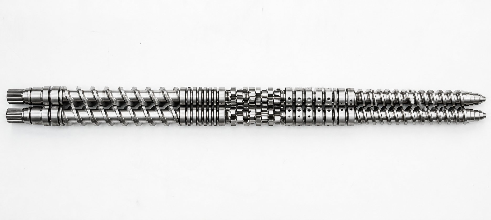
Knowing which elements exist and what they are made of is only half the equation. The real engineering challenge - and where twin screw extruder screw profile design separates experienced compounders from everyone else - is deciding where each element sits along the barrel and why it belongs there. A screw profile is not a random assembly of parts. It is a deliberate sequence of functional zones, each engineered to transform the material one step further on its journey from raw pellets to finished melt. As NC State Extension puts it, configuring a screw for extrusion is a blend of art and science - and no gold standard exists because every material exhibits unique flow properties under different thermal and shear conditions.
Here is the zone-by-zone sequence an engineer follows when building a complete screw element configuration for a twin screw extruder, from the feed throat to the die face:
- Solids Conveying Zone - Large-pitch, deep-flight forward conveying elements (typically 1.5x to 2x screw diameter pitch) positioned directly beneath the feed port. Their job is simple: accept incoming pellets, powders, or fibers and move them downstream without restriction. Large lead elements create maximum free volume in the screw channels, accommodating low-bulk-density materials and preventing bridging or feed-port backup.
- Melting and Plastication Zone - A transition from small-pitch conveying elements to a progressive kneading block sequence. The conveying elements compress the material and build initial pressure, then kneading blocks take over. A proven strategy starts with 30-degree forward-stagger kneading blocks to ease material into the melting process, followed by 60-degree blocks that deliver stronger shear input, and finishing with 90-degree neutral blocks that act as a melt dam - forcing full barrel fill to guarantee complete melting.
- Melt Mixing Zone - A combination of kneading blocks and specialized mixing elements tailored to the required mixing type. Dispersive-dominant formulations (carbon black deagglomeration, filler breakup) lean on wide-disc kneading blocks at 45-degree to 60-degree stagger angles. Distributive-dominant tasks (pigment spreading, additive homogenization) call for gear mixing elements or narrow-disc kneading blocks at 30-degree stagger. Many profiles intersperse short conveying element segments between kneading sequences to relieve pressure and distribute energy input over a longer barrel length rather than concentrating it in a single, continuous block.
- Venting Zone - A melt seal created by reverse-pitch conveying elements or blister rings, positioned immediately upstream of the vent port, followed by large-pitch forward conveying elements directly beneath the vent opening. The melt seal blocks gas from migrating backward, while the large-pitch elements create a low fill level and thin melt layer that maximize the exposed free surface for efficient moisture, air, or volatile removal.
- Pressure Build-Up Zone - Tight-pitch forward conveying elements (0.5x to 0.75x screw diameter pitch) that generate the head pressure needed to push melt through the die. Some engineers also introduce single-flighted or wide-flighted elements in this final section to enhance pumping stability and prevent melt from surging or pulsating at the die exit.
Feed Zone Through Melting Zone Design Logic
The transition from solids conveying to melting is where most screw profile mistakes happen. An overly aggressive melting section - such as jumping straight from feed elements into reverse kneading blocks - can spike melt temperature far beyond the setpoint and degrade heat-sensitive polymers. As detailed in melting section configuration research, the best approach for most formulations uses a graduated ramp: 30-degree kneading blocks transition material gently from the conveying section, 60-degree blocks initiate substantial melting through controlled shear, and 90-degree neutral blocks ensure residence time is long enough to guarantee every particle is fully molten. For crystalline polymers with sharp melting points, adding a reverse kneading block at the end of this sequence increases restriction and prevents unmelted solids from sneaking past.
An alternative strategy separates kneading blocks with short conveying element segments - imagine two or three kneading blocks followed by a forward conveying element, then another kneading group, repeated down the melting zone. This spreads total energy input over a greater barrel length, keeping melt temperature lower and more uniform. Screw elements for plastic twin screw extruder melting zones should always be selected with the polymer's thermal sensitivity in mind: what works for a robust polyethylene compound can easily scorch a PLA or EVOH formulation.
Mixing and Venting Zone Configuration
Downstream of the melting zone, the melt enters the mixing section - and this is where screw element configuration on a twin screw extruder becomes most application-specific. A masterbatch line blending 50% TiO2 into a carrier resin needs intense dispersive kneading. A flexible PVC compound with heat-sensitive stabilizers requires the gentlest distributive mixing achievable. The choice between kneading blocks, gear elements, toothed elements, and screw mixing elements in this zone determines both product quality and melt temperature.
One practical principle applies across nearly all formulations: avoid clustering too many kneading blocks in an unbroken sequence. Excessive back-to-back kneading overshears the melt, drives temperature up unpredictably, and can even cause extruder surging from uneven flow. Interspersing conveying elements between kneading groups - a practice emphasized in twin screw combination principles - keeps material moving, redistributes energy, and gives barrel cooling zones a chance to extract excess heat.
The venting zone follows a strict logic. Reverse-pitch elements or blister rings upstream create a pressurized melt seal. Immediately downstream at the vent port, large-lead conveying elements drop fill level dramatically, creating a thin melt film with maximum surface exposure. After the vent, smaller-pitch elements recompress the melt and re-establish forward pressure. Getting this sequence wrong - using too-short a reverse element or too-small a pitch under the vent - leads to either vent flooding or insufficient volatile removal.
Pressure Build-Up and Die Discharge Optimization
The final barrel section is often overlooked, but it directly governs die stability and product dimensional consistency. Tight-pitch forward conveying elements progressively compress the melt and build the pressure head needed to force material through the die or pelletizer. Gradually reducing the lead - rather than jumping to the smallest pitch in one step - prevents sudden pressure spikes that can cause melt fracture or inconsistent strand diameters.
For twin and single screw extruder screw elements alike, the pressure zone is where the OD/ID ratio discussed earlier becomes critical. High-viscosity engineering resins demand sustained torque at low speed, and the shaft must withstand this load over the entire final section. Running shallow-channel, tight-pitch elements on a machine with marginal torque capacity can stall the drive or twist the shaft.
Every element position in this zone-by-zone framework represents a controllable variable. Swapping a single kneading block for a conveying element in the melting zone reduces melt temperature by several degrees. Adding one additional reverse element before the vent port deepens the melt seal and improves volatile extraction. Shortening the pressure build-up section by removing a tight-pitch segment lowers back pressure and increases throughput - but risks die instability. These adjustments are small, targeted, and measurable, which is exactly what makes modular screw elements for a plastic twin screw extruder so powerful: the ability to iterate without starting from scratch.
Of course, even the most carefully sequenced profile will deteriorate over time. The real-world challenge is recognizing when element wear has shifted your carefully tuned geometry out of spec - and knowing exactly what to inspect before a subtle dimensional change becomes a costly quality failure.
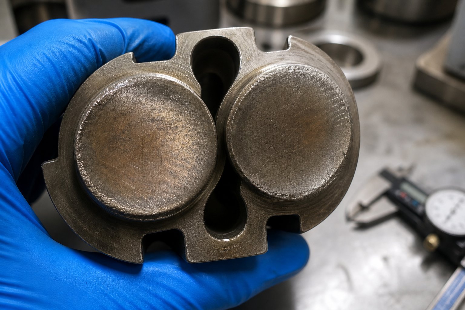
Screw Element Wear Patterns and Maintenance Strategies
A screw profile that ran flawlessly during commissioning does not stay that way forever. Hard fillers grind down flight edges, corrosive polymers eat into polished surfaces, and metal-to-metal contact scores element tips - all while the extruder keeps turning. The trouble is that wear rarely announces itself with a dramatic failure. Instead, it creeps in as a slow, quiet shift: a few percent less throughput, a slightly higher melt temperature, a pigment dispersion that used to be perfect and now shows faint streaks. Recognizing what is wearing, where it is happening, and when to act is the difference between a planned 30-minute element swap and an unplanned two-day shutdown.
Common Wear Patterns and Root Causes
Not all wear looks the same, and each pattern points to a different root cause. Understanding the mechanism tells you which elements to inspect first - and which metallurgy upgrade might be warranted.
Adhesive wear on kneading block tips is among the most common damage modes in abrasive-filler compounding. When hard particles like glass fiber or calcium carbonate are trapped between a kneading disc tip and the barrel wall, they act like sandpaper under pressure. Over time, the disc tip radius rounds off and the radial clearance between element and barrel grows. As industry maintenance guidance notes, the effect is strongest in feeding, melting, and glass-fiber addition zones - precisely where kneading blocks do their heaviest work. In severe cases, metal-to-metal contact develops between intermeshing screws when original clearances are consumed, leading to scoring, abnormal noise, and torque fluctuation.
Erosive wear on conveying element flights follows a different pattern. Glass-fiber-filled compounds act like a liquid abrasive stream flowing across the leading edge of each flight. The flight tips lose their sharp, squared geometry and become rounded - reducing conveying efficiency and allowing more melt to slip backward over the worn edge. You will notice this as a gradual drop in output at the same screw speed, often accompanied by unstable die pressure.
Corrosive pitting from halogenated polymers is the most chemically aggressive failure mode. PVC releases hydrochloric acid during processing; fluoropolymers generate hydrofluoric acid. These acids attack the element surface at a molecular level, creating pits, surface roughness, and localized material loss that accelerates further mechanical wear. As one practical guide emphasizes, a chemically damaged surface becomes far more vulnerable to abrasive friction - meaning corrosion and abrasion often compound each other in a destructive cycle.
Inspection Criteria and Measurement Methods
Catching wear before it reaches a critical threshold requires a consistent, measurement-driven inspection routine. Relying on visual checks alone leaves too much to chance - dimensional losses of just a few tenths of a millimeter can shift process performance noticeably. Here are the key checkpoints every twin screw extruder element wear inspection should cover:
- Outer diameter measurement - Use a flight micrometer to measure the OD at multiple points along each element. Compare results to the original design diameter. A clearance increase of less than 30% from the original value may allow continued operation with process adjustments; a flight height reduction exceeding 50% of the original dimension signals that conveying and mixing functions are compromised and the element should be replaced.
- Flight edge sharpness - Place a smaller screw element on a precision granite block or flat reference surface to visually inspect rounding of the flight edges. As Graham Engineering's maintenance guidance notes, screw flights should maintain their squared edges - rounding indicates progressive abrasive wear and reduced sealing between flight tip and barrel wall.
- Screw-to-barrel and screw-to-screw clearance - Measure the gap between the element OD and barrel ID using feeler gauges or bore gauges. In the intermeshing zone, increased screw-to-screw clearance degrades the self-wiping function and raises the risk of material stagnation and degradation.
- Spline bore inspection - Use go/no-go gauges to check the internal spline profile of each element. A worn spline bore introduces play between the element and shaft, causing rocking, uneven load distribution, and potential shaft damage under high torque.
- Visual inspection for cracking, pitting, or surface damage - Look for cracks along kneading disc faces, corrosive pitting on element surfaces, chrome plating that is flaking or peeling, and any discoloration patterns that suggest localized overheating or chemical attack.
Recording every measurement in a maintenance log - and trending values over time - transforms raw numbers into actionable intelligence. A single reading tells you where you stand today; a trend line tells you when you will hit a replacement threshold.
Replacement Strategies for Minimum Downtime
Two fundamentally different philosophies govern twin screw extruder screw element replacement: reactive and preventive. Each carries distinct risks and costs.
Reactive replacement means running elements until a quality problem, throughput loss, or mechanical failure forces a shutdown. It minimizes upfront spare-parts inventory but maximizes unplanned downtime. When a kneading block fails mid-run on a 24/7 production line, you are not just paying for the replacement element - you are paying for lost output, scrapped off-spec material, and emergency freight to get the part on-site.
Preventive scheduled replacement flips the equation. Elements are pulled and measured at fixed intervals - typically every 3,000 to 5,000 operating hours, or sooner after processing highly abrasive formulations. When measured dimensions cross a predefined threshold (for example, OD loss exceeding a set percentage), the element is retired regardless of whether production symptoms have appeared yet. This approach costs more in spare-parts inventory but virtually eliminates surprise failures.
A practical middle ground combines both: run a preventive measurement schedule, but stock critical spare elements - especially kneading blocks and reverse elements in the highest-wear zones - so that any element flagged during inspection can be swapped immediately during the same planned maintenance window. As maintenance best practices emphasize, treating the screw-and-barrel as a system matters too. Replacing only a worn screw element while ignoring a mating barrel segment that has also opened up may not restore full performance - you could end up chasing the same throughput loss with a brand-new part.
Knowing when to replace is only half of the maintenance equation. The other half - knowing exactly how to specify and source the right replacement element so it arrives on time and fits perfectly - is where procurement decisions can either save a production run or extend the downtime you were trying to avoid.
How to Specify and Source Screw Elements Effectively
A worn kneading block sits on your workbench, measured and flagged for replacement. You know the geometry, the material grade, and exactly where it goes on the shaft. But turning that knowledge into a correctly manufactured replacement - one that arrives on time, fits the spline, and matches the original tolerances - is where many procurement efforts stall. Ordering screw elements for a twin screw extruder is not like ordering fasteners from a catalog. Each element is defined by a unique combination of dimensional, metallurgical, and geometric parameters, and getting any one of them wrong means the part either does not fit or does not perform.
Whether you are replacing a single element after a wear inspection or specifying a complete set for a new build, three proven sourcing methods cover virtually every scenario you will encounter.
Three Methods for Specifying Screw Elements
Method 1: Ordering by OEM part number. If your extruder came from a major manufacturer - Coperion, KraussMaffei, Leistritz, JSW, or similar - every element on the shaft has an assigned part number tied to that machine's engineering documentation. Providing this number to a supplier is the fastest path to an accurate replacement because the part number encodes element type, pitch, stagger angle, disc count, length, material grade, and dimensional tolerances in a single reference. The catch? OEM-sourced elements typically carry premium pricing and longer lead times, especially if the manufacturer routes orders through regional distributors rather than shipping direct from the factory.
Method 2: Supplying engineering drawings or CAD files. When OEM part numbers are unavailable - or when you are working with a custom screw profile that deviates from the original machine configuration - detailed engineering drawings become the primary specification tool. A proper drawing should include all critical dimensions (OD, ID, length, pitch, number of tips or discs, stagger angle), material callouts, surface treatment requirements, and geometric tolerances. CAD files in STEP or IGES format are even better because they eliminate ambiguity around complex features like tooth profiles on gear mixing elements or the helical geometry of slotted SMEs. Many China twin screw extruder element manufacturers are fully equipped to work from customer-supplied drawings and produce elements that meet or exceed OEM specifications at significantly shorter lead times.
Method 3: Reverse-engineering from physical samples or measured dimensions. This is the fallback when no part number exists and no drawing was ever created - a surprisingly common situation with older machines, second-hand equipment purchases, or extruders that have been modified over decades of production. The process is straightforward: you send a physical sample element (new or worn, though new is obviously preferred) to the manufacturer, who measures every dimension using CMM equipment, replicates the spline profile, and produces a matching replacement. Alternatively, you can supply your own measured dimensions - OD, bore diameter, spline tooth count and profile, element length, pitch, and stagger angle - and the manufacturer machines to those specs. Suppliers like NANHAIYA produce modular screw segments, kneading blocks, and screw elements from drawings, samples, or measured dimensions, covering applications across compounding, pelletizing, masterbatch, and recycling lines. This reverse-engineering capability is especially valuable when sourcing replacements for discontinued machine models or proprietary screw designs where the original manufacturer no longer supports the product.
Critical Data Points for Accurate Procurement
Regardless of which method you use, the supplier needs a specific set of data points to manufacture the element correctly. Missing even one parameter can result in a part that slides onto the shaft but fails to deliver the expected processing function - or worse, does not fit at all. Before contacting any supplier, prepare the following:
- Element type - Conveying element, kneading block, gear mixing element, screw mixing element, blister ring, or other specialized geometry.
- Shaft diameter and spline profile - The bore diameter, number of spline teeth, tooth pitch, and engagement depth. This is the single most critical fit parameter - a mismatch here means the element cannot mount on the shaft.
- Outer diameter (OD) - Must match the barrel bore with correct radial clearance. Specify the nominal OD and the tolerance band.
- Element length - Measured along the shaft axis. Even a 1 mm error can create gaps or interference in a tightly packed profile.
- Pitch (for conveying elements) - The axial distance per full revolution of the flight. Specify forward or reverse direction.
- Number of tips or flight starts - Single-flighted, double-flighted, or triple-flighted for conveying elements; bilobal or trilobal for kneading blocks.
- Disc count and stagger angle (for kneading blocks) - The number of individual discs and the angular offset between each pair. Also specify forward, neutral, or reverse advance direction.
- Material grade - The specific steel designation (38CrMoAlA, W6Mo5Cr4V2, CPM 10V, etc.) or a performance-based specification describing the required hardness and wear or corrosion resistance.
- Surface treatment - Gas nitriding, ion nitriding, hard chrome plating, HVOF coating, or none. Include the target case depth or coating thickness if applicable.
- Quantity and identification - Number of pieces required and any position-specific marking or labeling convention used on your production floor.
Sounds like a lot of detail? It is - and that is the point. A China twin screw extruder element factory that does not ask you for this level of specification data before quoting is either making assumptions or planning to ask later, which delays delivery. Suppliers who request these parameters upfront, confirm them in a formal drawing review, and issue a dimensional inspection report with the finished parts are the ones whose elements fit right the first time.
Evaluating Suppliers for Quality and Lead Time
The specification data gets the geometry right. Supplier selection determines whether that geometry arrives in the correct material, at the correct hardness, within an acceptable timeframe.
Lead time varies dramatically across the market. OEM replacements from European or Japanese manufacturers commonly require 8 to 16 weeks, depending on the element type and current production backlog. Independent manufacturers - particularly experienced China twin screw extruder elements suppliers - often deliver in 3 to 6 weeks for standard geometries, and some maintain inventories of common element blanks (popular shaft diameters and OD sizes) that can be finish-machined and shipped even faster. If your production line cannot tolerate multi-month waits for critical spare parts, working with a manufacturer who stocks semi-finished blanks is a significant operational advantage.
Quality verification separates reliable suppliers from risky ones. At minimum, demand the following from any prospective source:
- Material test certificates (EN 10204 Type 3.1 or equivalent) confirming the chemical composition and mechanical properties of the steel used.
- Hardness test reports at multiple points on each element - flight tip, disc face, and bore - verifying uniform heat treatment.
- Dimensional inspection records comparing finished dimensions against the drawing tolerances you specified.
- Surface treatment documentation confirming nitriding depth, coating thickness, or plating adhesion test results as applicable.
As the SKR supplier evaluation framework emphasizes, verifying raw material quality through spectrometer testing and reviewing metallographic analysis reports are essential steps that distinguish qualified manufacturers from assemblers who simply purchase and resell. Checking whether the supplier holds ISO 9001 certification - and whether that certification scope actually covers screw element manufacturing rather than just trading - adds another layer of confidence.
Compatibility expertise is the final filter. The best element suppliers do not just machine metal to a drawing - they understand how different element geometries interact with specific extruder platforms. They can flag potential issues such as spline profile mismatches between generation variants of the same machine, or material grade substitutions that change wear characteristics in your specific processing environment. This kind of application knowledge turns a parts vendor into a genuine technical partner - and it is worth prioritizing during supplier qualification, especially if your operation runs multiple extruder brands or processes a wide range of formulations.
With the right specification data prepared and a qualified supplier selected, procurement shifts from a reactive scramble into a repeatable, controlled process - one that supports the inspection-driven maintenance strategy discussed earlier and keeps your screw profiles performing at the level they were designed to deliver.
Turning Screw Element Knowledge into Better Extrusion Results
Specification data submitted, supplier qualified, replacement elements on order - the procurement cycle closes, but the engineering cycle never really stops. Every concept covered in this article feeds into a single objective: making screw element decisions that improve product quality, protect equipment, and reduce unplanned downtime. The difference between a compounder who guesses at element selection and one who engineers it comes down to a handful of principles applied consistently.
Key Engineering Principles to Remember
Strip away the complexity, and the twin screw extruder screw element selection guide you have just worked through rests on four pillars:
- Match element geometry to the processing function required in each zone. Deep-flight, large-pitch conveying elements belong in the feed section - not the pressure build-up zone. Wide-disc kneading blocks at 60- to 90-degree stagger angles belong where dispersive deagglomeration is needed - not where a heat-sensitive resin is barely melted. Gear mixing elements deliver superior distributive mixing with minimal thermal penalty - making them the right tool when homogeneity matters more than particle breakup. Every element has a job, and placing it in the wrong zone wastes energy, degrades product, or both.
- Select materials based on the actual wear and corrosion environment, not default assumptions. Nitrided steel is perfectly adequate for unfilled polyolefins. It is a liability in a 40% glass-fiber nylon compound. PM-HIP steels and tungsten carbide composites cost more upfront but can extend element life by five to ten times in abrasive applications - a net savings when you factor in downtime, scrap, and emergency shipping. Corrosive polymers like PVC and fluoropolymers demand nickel-based alloys regardless of filler loading. Defaulting to the cheapest grade is not frugal; it is expensive in disguise.
- Design screw profiles as integrated systems, not collections of isolated elements. A kneading block does not operate in isolation - its performance depends on what sits upstream (conveying pitch, fill level, melt state) and downstream (pressure relief, venting, further mixing). Swapping one element changes the behavior of every element around it. Graduated kneading sequences, strategic conveying spacers between mixing groups, and properly sealed venting zones all reflect this systems-level thinking.
- Establish inspection-driven maintenance schedules to catch wear before it becomes failure. Measuring OD reduction, checking flight edge sharpness, inspecting spline bores with go/no-go gauges, and trending those values over operating hours transforms maintenance from guesswork into data. A preventive schedule based on throughput-hours or measured dimensional thresholds virtually eliminates surprise shutdowns - and stocking critical spares for high-wear positions ensures flagged elements can be swapped during planned windows rather than emergency stops.
Turning Knowledge into Better Screw Configurations
These principles only create value when they translate into action on your production floor. Start by auditing your current screw profiles against the zone-by-zone framework: is every element positioned where its geometry delivers the most benefit? Are your material grades aligned with the fillers and polymers you actually process today - not the ones you processed five years ago when the elements were originally specified? Are you measuring wear at consistent intervals, or waiting for quality complaints to trigger inspection?
Equally important is working with suppliers who can support this engineering-driven approach. Manufacturers that produce modular screw segments, kneading blocks, and elements from drawings, samples, or measured dimensions - such as NANHAIYA's segment screw program - give compounding, pelletizing, masterbatch, and recycling teams the flexibility to iterate on screw configurations without being locked into a single OEM's pricing or lead-time constraints. That flexibility, combined with the technical framework outlined here, puts screw element optimization squarely within your control.
The best screw profile is not the one with the most expensive elements - it is the one where every element is matched to its zone function, built from the right material for the processing environment, and replaced before wear compromises the performance it was designed to deliver.
Frequently Asked Questions About Screw Elements for Twin Screw Extruders
1. What are the main types of screw elements used in a twin screw extruder?
Twin screw extruders use three foundational element categories: conveying elements that transport material forward or backward using helical flights with varying pitch lengths; kneading blocks made of stacked lobe-shaped discs with adjustable stagger angles (30, 45, 60, or 90 degrees) for melting and mixing; and mixing elements such as toothed or gear designs that split and recombine melt streams for distributive blending. Beyond these, specialized elements like blister rings for melt sealing and screw mixing elements (SMEs) with slotted flights address tasks where standard categories fall short.
2. How does stagger angle on kneading blocks affect mixing performance?
Stagger angle is the angular offset between consecutive discs in a kneading block and directly controls the balance between conveying and mixing intensity. A 30-degree stagger maintains strong forward conveying with mild, mostly distributive mixing. A 45-degree angle increases shear while reducing forward push. A 60-degree offset delivers strong dispersive shear with minimal conveying. A 90-degree (neutral) block has zero conveying ability, creating 100% barrel fill and the most intense mixing. Higher stagger angles generate more mechanical energy, which raises melt temperature - a critical trade-off when processing heat-sensitive polymers.
3. What is the difference between distributive and dispersive mixing in twin screw extrusion?
Distributive mixing spatially rearranges and redistributes minor components - pigments, additives, or fillers - evenly throughout the polymer melt without changing particle size. Dispersive mixing applies mechanical stress to break down cohesive domains such as agglomerates, droplets, or fiber bundles into smaller sizes. Effective compounding requires both: dispersive mixing reduces particles to their target size, and distributive mixing ensures those particles are spread uniformly. Narrow kneading blocks at 30-degree stagger and gear mixing elements (ZME/TME) favor distributive mixing, while wide kneading blocks at 60 to 90 degrees drive dispersive action.
4. How do I choose the right material grade for twin screw extruder screw elements?
Material selection should match the dominant wear or corrosion mechanism in your process. Nitrided steel (e.g., 38CrMoAlA) suits unfilled or lightly filled polyolefins at the lowest cost. Through-hardened tool steels (e.g., W6Mo5Cr4V2) handle medium filler loadings like 40% CaCO3 or talc. PM-HIP steels (CPM 9V, CPM 10V) are needed for high glass-fiber loading above 30%. Tungsten carbide composites (WR5, WR13) survive extreme abrasion from 50-60% glass fiber or metal-contaminated recycle. Corrosive polymers like PVC or fluoropolymers require nickel-based corrosion-resistant alloys regardless of filler content. Suppliers like NANHAIYA can manufacture elements in specified material grades from drawings or samples.
5. When should twin screw extruder screw elements be inspected and replaced?
A preventive inspection schedule every 3,000 to 5,000 operating hours is recommended, with more frequent checks after processing highly abrasive formulations. Key inspection points include measuring outer diameter reduction with a flight micrometer (replace when flight height loss exceeds 50%), checking flight edge sharpness for rounding, verifying screw-to-barrel clearances with feeler gauges, and inspecting spline bores with go/no-go gauges. Trending measurements over time helps predict when elements will reach replacement thresholds, allowing planned swaps during scheduled maintenance windows rather than costly emergency shutdowns.
Written by
Nanhaiya Technical Team
Zhoushan Nanhaiya Plastic Machinery Co., Ltd.
The Nanhaiya technical team supports screw and barrel manufacturing projects through application review, technical communication, custom manufacturing coordination, and production and quality control.
Discuss Your Application
Related Articles
More insights on screw barrel technology and plastics processing.
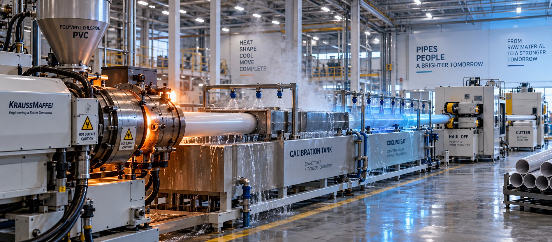
PVC Pipe Making Machine: What No Supplier Will Tell You First
Oct 21, 2026
Learn what a PVC pipe making machine really includes, how each component works, extruder types compared, maintenance schedules, defect fixes, and buying tips.
Read Article
What Your Film Extrusion Machine Datasheet Won't Tell You
Oct 20, 2026
Film extrusion machine guide covering blown vs cast processes, multilayer configurations, screw specs, resin selection, and supplier evaluation for production engineers.
Read Article
Raw Scrap to Perfect Pellets: Plastic Pelletizing Machine Guide
Oct 19, 2026
Learn how a plastic pelletizing machine converts scrap into uniform pellets. Covers cutting methods, extruder types, quality control, costs, and maintenance.
Read ArticleLooking for something else?
Search by material, symptom or product and jump straight to the relevant page.
These are navigation suggestions based on keyword matching — not a quotation, not a delivery commitment, and not a substitute for engineering review. Final specification is confirmed by our engineers against your drawings and processed material.
Need help with screw barrel selection?
Share your machine model, processed material and application. Our team can help with pricing and technical support.