

Why Screw Barrel Replacement Is the Most Critical Maintenance Decision You Make
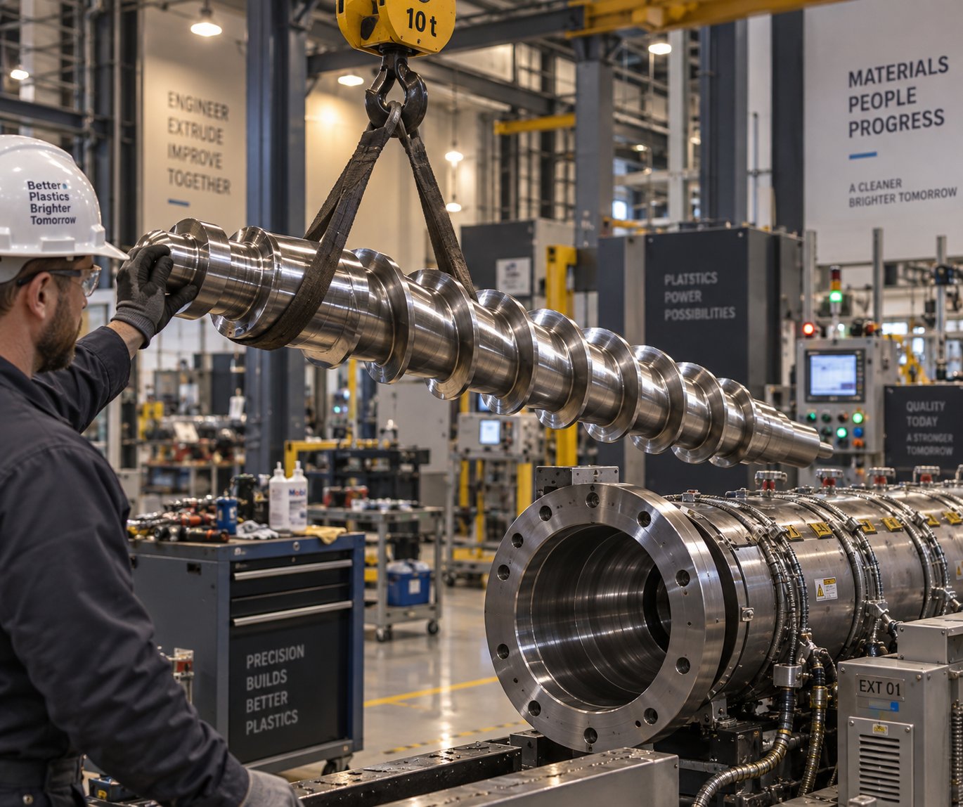
Screw barrel replacement is the process of removing a worn extruder screw and barrel — or injection molding plasticating assembly — and installing new or refurbished components to restore original melt quality, output rates, and energy efficiency. It sounds straightforward, yet the timing, specification, and execution of this single decision ripple through every metric a plastics processor tracks: part quality, cycle time, scrap rate, and electricity spend.
Defining Screw Barrel Replacement in Plastics Processing
Think of the screw barrel as the heart of every plasticating machine. The extruder screw conveys, compresses, and shears raw polymer, while the extruder feed barrel provides the bore surface and heat zones that turn solid pellets into a uniform melt. Together, these components govern how efficiently resin converts into sellable product. When clearances between the screw flight outside diameter and the barrel bore grow beyond acceptable limits, leakage flow increases, melt temperature climbs, and throughput drops — often so gradually that operators compensate with small parameter tweaks without realizing the true root cause.
A worn screw barrel does not fail suddenly — it degrades gradually, silently raising scrap rates and energy costs long before a catastrophic shutdown.
Who This Guide Serves and How to Use It
This playbook is built for two audiences. If you are a hands-on technician pulling screws and aligning barrels, you will find step-by-step measurement and installation procedures. If you are a maintenance manager or plant engineer approving capital spend, you will find the diagnostic frameworks and cost-comparison tools needed to justify — or defer — a replacement purchase with data rather than gut feel.
The chapters ahead walk through the full lifecycle: identifying the specific wear type damaging your screw barrel, reading machine symptoms before they become emergencies, measuring clearances with precision, choosing between replacement and repair, specifying the right component, executing the physical swap safely, and validating results after startup. Each section builds on the last, so the guide functions as both a cover-to-cover resource and a quick-reference tool you can revisit at each stage of the process.
The real cost of a worn plasticating unit rarely shows up on a single invoice. It hides inside rising energy bills, climbing scrap percentages, and the slow erosion of throughput that operators mask with incremental adjustments. Understanding exactly how that wear develops — and what it looks like on a removed component — is where smart replacement planning begins.
Identifying the Four Types of Screw and Barrel Wear
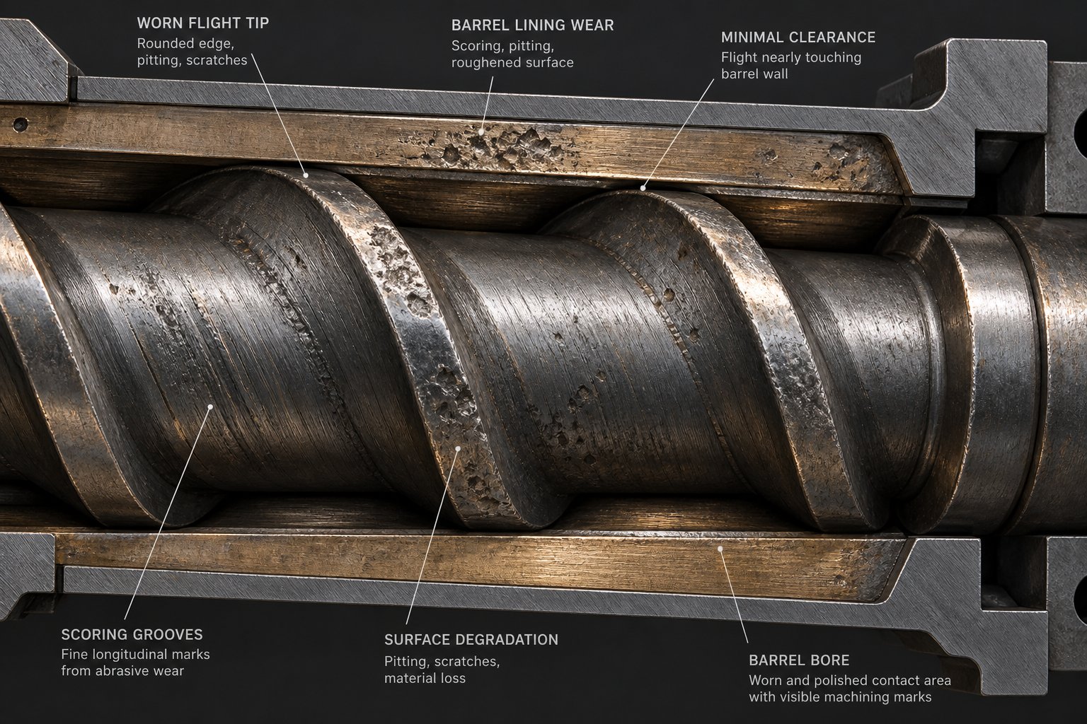
Every degraded screw barrel tells a story — but only if you know how to read it. The wear patterns etched into extruder screws and barrels fall into four distinct categories, each driven by a different physical mechanism. Recognizing which type is at work on your components shapes every downstream decision: the urgency of your screw barrel replacement, the metallurgy you specify for the new part, and the process changes you make to extend service life. Skipping this diagnostic step is like replacing a tire without checking alignment — you will burn through the new component just as fast.
Adhesive and Abrasive Wear Explained
Adhesive wear occurs when two metal surfaces slide against each other under load without adequate separation. Picture what happens inside a plasticating barrel when the polymer film between the screw flight tip and the bore thins out — microscopic high points on each surface bond momentarily, then shear apart. Material literally transfers from one surface to the other. You will notice galling, smearing, or material buildup on removed screws, often concentrated in the transition zone where pressure is highest and the melt film is not yet fully developed.
Several processing conditions accelerate adhesive wear. Running at high screw speeds with resins that have low melt viscosity reduces the lubricating polymer layer. Poor barrel-to-gearbox alignment causes the screw to ride against the bore unevenly, creating localized metal-to-metal contact. Glass-filled polyamides at 40-50% loading are especially problematic — uncompressed solids can deflect the screw into the barrel wall, triggering direct contact between the flight tip and bore surface.
Abrasive wear is the more familiar culprit, and it works differently. Hard particles — glass fibers, mineral fillers, ceramic microspheres, or metal powders — act like sandpaper dragged between the screw and barrel surfaces. Each reinforcement particle gouges a tiny channel, and millions of those channels add up to measurable diameter loss. Visually, abrasive wear leaves distinct scoring, grooves, and a roughened surface finish on both extruder barrels and flight tips. The damage tends to be distributed along the full bore length, though it concentrates wherever shear rates peak.
Glass-filled nylons, highly loaded PBT compounds, and recycled resins containing contaminants are the worst offenders. Even modest filler levels — 10-15% glass — dramatically shorten component life on standard nitrided surfaces.
Corrosive and Fatigue Wear Patterns
Corrosive wear introduces chemistry into the equation. Certain polymers release aggressive acids during melt processing: PVC generates hydrochloric acid, acetals produce formic acid, and fluoropolymers release hydrofluoric acid — one of the most destructive substances a barrel bore will ever encounter. Flame retardants and foaming agents create additional corrosive byproducts. These acids dissolve protective oxide layers on metal surfaces, leaving pitting, discoloration, and roughened textures that are easy to distinguish from mechanical scoring. Standard bimetallic, nitrided, or tool-steel barrels can be severely damaged by fluoropolymers in a very short time.
Corrosive wear rarely acts alone. It weakens surfaces and accelerates adhesive or abrasive mechanisms already in play, creating a compounding degradation cycle. Processing conditions that intensify it include extended residence times at melt temperature, poor venting that traps corrosive off-gases, and frequent startups that expose hot metal surfaces to condensation.
Fatigue wear is the least visible — and often the most dangerous. Extruder screws endure continuous cyclic loading: fluctuating torque, alternating bending stresses from barrel misalignment, and pressure pulsations during surging. Over thousands of operating hours, microscopic cracks nucleate below the surface, propagate through repeated stress cycles, and eventually cause surface spalling, flight cracking, or even catastrophic screw fracture. Fatigue signatures include surface spalling, subsurface cracking, and pitting that appear without the scoring or chemical discoloration associated with other wear types.
High-torque operations, frequent cold starts, and thermal cycling between production runs all accelerate fatigue. Because fatigue cracks grow invisibly, this wear type often progresses undetected until a sudden failure stops the line.
Matching Wear Type to Replacement Material Selection
Identifying the dominant wear mechanism on your removed components is not an academic exercise — it directly dictates the metallurgy and surface treatment you should specify for the replacement. Swapping a corroded barrel for another standard nitrided bore while still running PVC is simply buying the same failure on a new part.
For abrasive applications, bimetallic barrels with tungsten-carbide-rich linings paired with tool-steel or cobalt-hardfaced flight tips deliver the best resistance. Corrosive resins demand nickel-based alloys — Hastelloy, Inconel, or HIP (hot isostatic pressing) barrels — that resist chemical attack where standard alloys fail. Adhesive wear responds to improved surface hardness and better lubricity coatings, while fatigue resistance calls for high-quality base steels with controlled heat treatment and stress-relieved flight roots.
The table below summarizes the relationship between each wear type and the replacement specification it demands:
| Wear Type | Root Cause | Visual Signature | Typical Resins Involved | Recommended Replacement Metallurgy |
|---|---|---|---|---|
| Adhesive | Metal-to-metal contact from insufficient melt-film separation or misalignment | Galling, smearing, material transfer on flight tips and bore | Low-viscosity resins; heavily filled compounds causing screw deflection | Through-hardened or nitrided steel with enhanced surface hardness; ensure barrel alignment |
| Abrasive | Hard filler particles (glass fiber, mineral, metal powder) scouring surfaces | Scoring, grooves, roughened bore and reduced flight OD | Glass-filled nylons, PBT, filled polyolefins, recycled resins with contaminants | Bimetallic barrel with tungsten-carbide lining; tool-steel or Colmonoy 83 hardfaced flights |
| Corrosive | Acid attack from off-gassing polymers, flame retardants, or foaming agents | Pitting, discoloration, surface roughening without mechanical scoring | PVC, acetals, fluoropolymers, flame-retardant compounds, PLA bioplastics | Nickel-based alloys (Hastelloy, Inconel); HIP barrels; stainless steel components |
| Fatigue | Cyclic stress from torque fluctuation, thermal cycling, and pressure pulsation | Subsurface cracking, spalling, flight root fractures with no chemical discoloration | Any resin under high-torque, frequent start-stop, or thermally cycled conditions | High-quality alloy steel base with controlled heat treatment; stress-relieved flight geometry |
Keep in mind that real-world components rarely show a single pure wear type. A screw running glass-filled PVC, for instance, will face abrasive and corrosive attack simultaneously, demanding a replacement that addresses both mechanisms. The key is to identify the dominant pattern, then cross-check for secondary damage before finalizing your specification.
Knowing what destroyed the old component points you toward the right replacement material — but it does not yet tell you when to act. The next critical skill is reading the machine itself: translating subtle shifts in output, melt temperature, and part quality into an early warning that wear has crossed the line from tolerable to costly.
Warning Signs Your Extruder or Injection Machine Needs Attention
A worn extrusion screw or extruder barrel rarely announces itself with a dramatic failure. Instead, it whispers — through incremental drops in output, a few extra degrees of melt temperature, or a slow uptick in rejected parts that operators attribute to resin variability or ambient temperature swings. The challenge is not whether your machine will send these signals, but whether your team recognizes them early enough to plan a screw barrel replacement on your schedule rather than the machine's.
Connecting specific performance shifts to wear locations and types turns vague suspicion into actionable intelligence. Equally important, though, is ruling out problems that look like screw or barrel degradation but originate somewhere else entirely.
Machine Symptoms That Signal Screw or Barrel Degradation
Imagine you are running a familiar product on a line that has been stable for months. One week, you notice the operator has bumped screw speed up a few RPM to hold rate. The following week, discharge temperatures are running 5-8 degrees higher than the historical baseline. Scrap bins are filling a little faster. None of these shifts alone trigger an alarm — but together, they paint a clear picture of increasing flight clearance and reduced pumping efficiency.
Here are the key symptoms worth monitoring, and what each one typically points to:
- Declining output at constant RPM. When the clearance between the screw flight tip and the barrel bore widens, polymer leaks backward over the flights instead of being conveyed forward. You need higher screw speeds to maintain the same throughput — a hallmark of advancing wear. As Plastics Technology notes, a worn 100-mm screw running PE at constant rate required steadily increasing screw speeds, and once flight clearance grew large enough, a 13% rate reduction became unavoidable.
- Rising melt temperature or energy consumption. Higher screw speeds generate more shear heat. Simultaneously, the thicker polymer film in a worn clearance zone reduces heat-transfer efficiency at the barrel wall, pushing discharge temperatures higher even without any change to barrel heater setpoints.
- Inconsistent part weight or wall thickness. Leakage flow over worn flights creates pressure instability in the metering zone. In injection molding screws and barrels, this translates directly to shot-to-shot weight variation. In extrusion, you will see machine-direction gauge fluctuation in film, sheet, tubing, or pipe.
- Increased scrap, burn marks, or degradation. Elevated melt temperatures push heat-sensitive resins past their processing window. Residence time in dead spots created by worn geometries compounds the problem, producing discoloration, black specks, or reduced mechanical properties.
- Visible unmelts or gel streaks. Worn feed-zone flights lose their ability to compact and convey solids efficiently. Unmelt pellets or partially plasticized gel particles pass through the barrel and show up as inclusions in the finished product or as debris captured on screen packs.
- Excessive barrel-zone temperature overrides. When operators keep raising zone temperatures to compensate for poor melting or low output, it is a strong indicator that the screw is no longer doing its mechanical work effectively. The heaters are asked to make up for lost shear energy — a costly and thermally inefficient trade-off.
The diagnostic matrix below maps each symptom to the most likely wear location, probable wear type, and urgency level. Use it as a first-pass filter before pulling the screw for inspection:
| Observable Symptom | Likely Wear Location | Probable Wear Type | Urgency Level |
|---|---|---|---|
| Declining output at constant RPM | Metering zone flights; barrel bore in metering section | Abrasive or adhesive | Moderate — plan measurement within 2-4 weeks |
| Rising melt temperature at same rate | Transition and metering zone flights | Abrasive (clearance-driven) | Moderate — monitor weekly |
| Inconsistent part weight or wall thickness | Metering zone; check ring (injection); barrel bore | Abrasive or adhesive | High — quality impact is immediate |
| Burn marks, discoloration, or degradation | Metering zone dead spots; worn barrel bore near discharge | Corrosive accelerated by thermal exposure | High — product and safety risk |
| Unmelts or gel streaks in product | Feed zone flights; transition zone compression area | Abrasive (flight tip loss reducing solids conveying) | Moderate to high — depends on product criticality |
| Frequent barrel-zone temperature overrides | Feed and transition zones (compensating for lost shear) | General wear — multiple types possible | Moderate — investigate root cause promptly |
| Pressure surging or fluctuating head pressure | Transition zone (solids-bed breakup); feed zone | Abrasive or adhesive (solids wedging) | High — downstream quality and safety concern |
Ruling Out Upstream and Downstream Component Issues
Here is where experienced maintenance teams save their plants thousands of dollars: not every symptom on the list above proves that the screw or barrel is the problem. Several upstream and downstream conditions produce nearly identical performance signatures — and ordering a replacement before checking these items means spending capital on a component that was never the root cause.
Consider these common mimics:
- Worn or overheated feed throats. A feed throat that has lost its cooling efficiency allows pellets to soften and bridge prematurely, restricting material flow into the screw. The result — reduced output and erratic feeding — looks exactly like feed-zone screw wear. Check the cooling water flow and throat bore condition before blaming the screw.
- Damaged or failing heater bands. A partially shorted or aged heater band can create cold spots or uncontrolled hot zones along the extruder barrel. As one equipment analysis found, poor contact between the heating element and barrel surface alone can produce temperature deviations of 10-15 degrees Celsius, which easily mimics the melt-quality issues caused by barrel bore wear.
- Faulty thermocouples. An aged or improperly seated thermocouple can feed inaccurate readings to the temperature controller, causing the system to over- or under-heat a zone. If the displayed temperature reads 230 degrees but the actual barrel surface sits at 250 degrees, you will see degradation symptoms that have nothing to do with mechanical wear.
- Worn thrust bearings. A degraded thrust bearing allows the screw to float axially, changing flight-to-bore clearances dynamically during operation. The inconsistent output and pressure fluctuations this produces are virtually indistinguishable from distributed bore wear — until you inspect the bearing itself.
- Screen pack loading or adapter restrictions. A clogged screen pack steadily raises head pressure, reduces output, and increases melt temperature — a combination that mirrors the progressive symptoms of screw wear. Trending differential pressure across the filtration device isolates this cause quickly.
A practical approach is to treat diagnosis as a two-stage filter. First, verify all ancillary components — heaters, thermocouples, feed throat, thrust bearing, screen pack, and drive system — are functioning within specification. Second, if symptoms persist after those checks, proceed to the quantitative screw and barrel measurement procedures that convert suspicion into hard numbers. That measurement data, not a hunch, should be the basis for every screw barrel replacement decision.
How to Measure Screw and Barrel Wear with Precision
Suspicion is free — but acting on suspicion is expensive. The symptoms discussed in the previous section tell you something is wrong, yet they cannot tell you how much wear exists or whether you have weeks, months, or minutes of usable life remaining. That answer comes from physical measurements of screw and barrel dimensions, compared against known tolerance limits. These numbers turn a vague hunch into a defensible capital decision, whether you are the technician pulling the screw or the maintenance manager approving the purchase order.
Bore Gauge and Micrometer Measurement Procedures
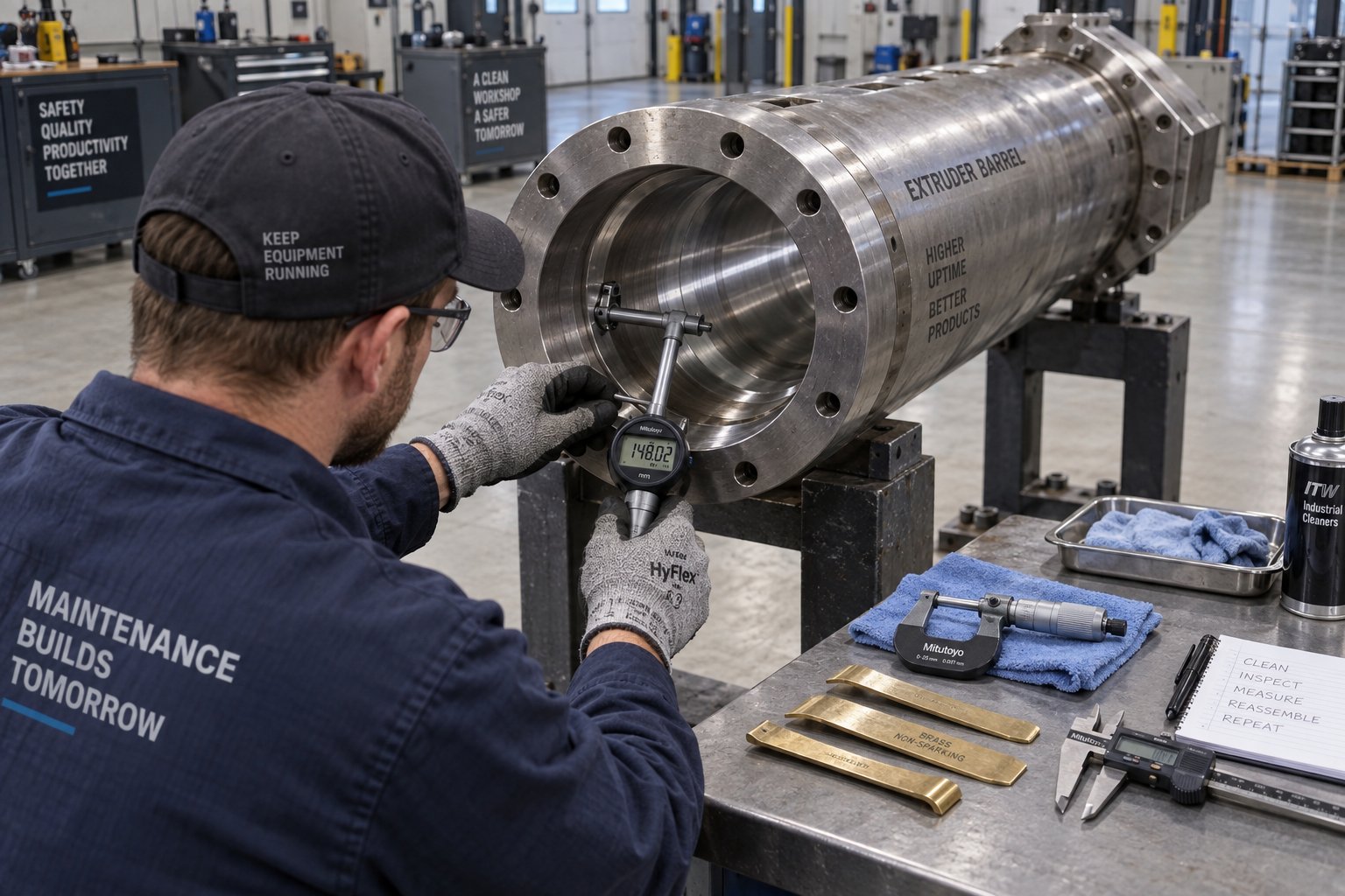
Two instruments do the heavy lifting here: a bore gauge for the barrel's internal diameter and an outside-diameter (OD) micrometer for the screw flight tips. The goal is to measure both components at multiple points along their length, then calculate the gap between them — the diametral clearance that governs pumping efficiency, leakage flow, and melt quality.
Before you pick up a gauge, preparation matters. All solidified resin must be cleaned from the screw surface — but never use a steel wire brush or aggressive abrasive material, as these can damage the flight surfaces and distort your readings. Brass scrapers and copper gauze are the standard cleaning tools. Place the screw on a clean, flat work surface — a granite inspection table is ideal for simultaneously checking straightness by rolling the screw and watching for bowing.
Follow this step-by-step procedure to capture reliable data from both the screw and barrel:
- Clean the screw thoroughly. Remove all plastic residue from flight tips, root diameter, and shank using brass tools and copper gauze. For stubborn buildup, dry ice blasting or an econ blast system works well without risking surface damage.
- Inspect for visible damage. Before measuring, examine the screw for cracks, pitting, galling, or broken flight edges. Note any damage and its location — these observations add context to the dimensional data.
- Measure the screw flight OD. Using an OD micrometer — ideally one modified with a bar that spans across the flights — measure the outside diameter of the screw at evenly spaced intervals along its entire length. Record each reading alongside its distance from the screw tip, covering the feed, transition, and metering zones.
- Record the measurement location. Use a tape measure to reference each reading's position along the screw length. Consistency in location is essential for trend comparison over time.
- Measure the barrel bore ID. Insert a calibrated bore gauge as far down each end of the barrel as you can safely reach. Take readings at multiple points — a minimum of every two to three diameters of length — and at two orientations (0 degrees and 90 degrees) at each point to check for ovality.
- Calculate diametral clearance. At each measurement station, subtract the screw flight OD from the barrel bore ID. This difference is the diametral clearance — the single most important number for evaluating screw and barrel condition.
- Compare to baseline. Measure each value against the original OEM specification or the last documented reading to quantify wear progression.
Understanding Diametral Clearance Thresholds
So you have a set of clearance numbers — what do they mean? Every extrusion screw barrel or injection unit ships with a designed clearance between flight tips and bore, typically a few thousandths of an inch per side depending on screw diameter. As wear progresses, this gap widens, and polymer leaks backward over the flights instead of being pumped forward.
Industry guidelines, such as the SPI Dimensional Guidelines referenced by plasticizing component specialists, categorize diametral wear into threshold levels. A common framework breaks it into three bands:
| Wear Level | What It Means | Recommended Action |
|---|---|---|
| Low | Early-stage wear; slight output decline may become noticeable at constant RPM | Continue running; document and re-measure at next scheduled interval |
| Medium | Measurable clearance increase; output loss, rising melt temperature, or quality drift becoming evident | Monitor closely; begin planning rebuild or replacement to avoid reactive downtime |
| High | Clearance well beyond design tolerance; significant throughput loss, energy waste, and quality defects | Rebuild or replace immediately — continued operation causes escalating cost |
Keep in mind that these thresholds vary by screw diameter, machine type, and application. A 2.5-inch extrusion screw barrel processing unfilled HDPE tolerates a different clearance than a 6-inch unit running 40% glass-filled nylon. Always consult your OEM manual for the specific limits that apply to your equipment. High-work barrier screws, for example, limit acceptable wear to 75 percent of the barrier flight clearance — a much tighter threshold than general-purpose designs.
Documenting Measurements for Long-Term Trend Analysis
A single set of measurements tells you where you stand today. A series of measurements taken at regular intervals tells you where you are headed — and that predictive power is what separates reactive maintenance from proactive planning.
Measurement without documentation is wasted effort — every reading should be logged with date, location along the barrel, and machine hours for trend analysis.
Set up a simple tracking log — a spreadsheet works well — with these fields for every barrel and screw measurement event:
- Machine ID and component serial number
- Date of measurement
- Total machine hours (or screw hours) at time of measurement
- Measurement location along the barrel length (distance from feed end)
- Barrel bore ID and screw flight OD at each station
- Calculated diametral clearance at each station
- Resin type and filler content being processed
- Notes on any visible damage, discoloration, or anomalies
Over two or three inspection cycles, you will have enough data to plot a wear-rate trend. A straightforward chart — machine hours on the x-axis, diametral clearance on the y-axis — reveals the slope of wear progression. That slope lets you project when clearance will reach the threshold requiring action, giving your team enough lead time to source a replacement, schedule downtime, and avoid a panic purchase at premium cost.
How often should you measure? Making screw and barrel measurement part of a planned preventive maintenance program is the industry best practice. For lines running abrasive or corrosive resins, quarterly inspections are a reasonable starting point. Less aggressive applications — unfilled polyolefins, general-purpose PS — may justify semi-annual or annual intervals. High-criticality production lines, where unplanned stops cost tens of thousands per hour, warrant the tighter schedule regardless of resin type.
Precise clearance data and a documented wear trend give you the confidence to answer the most consequential question in the entire replacement process: should you replace, repair, refurbish, or re-nitride? That decision framework — and the cost, risk, and service-life trade-offs behind each option — is where measurement data becomes financial strategy.
The Replace Versus Repair Decision Framework
Your clearance data is on the table. The wear trend chart slopes upward. The question is no longer if your barrel screws need attention, but what kind of attention delivers the best return on downtime and dollars. Jumping straight to a full screw barrel replacement feels decisive — but it is not always the smartest financial move. Conversely, patching a component that belongs in the scrap bin wastes money twice: once on the repair and again on the replacement you needed all along.
Four distinct paths exist, each suited to a different combination of wear severity, component condition, and production urgency. Choosing correctly hinges on matching the data you collected during measurement to the cost, risk, and longevity profile of each option.
Replace, Repair, Refurbish, or Re-Nitride — Defining Each Path
Full replacement means ordering a brand-new screw, barrel, or both — manufactured to the original OEM specification or, better yet, upgraded to a metallurgy that addresses the wear mechanism that consumed the previous component. This is the cleanest reset: you get factory-new dimensions, verified metallurgy, and a fresh service-life clock. It is also the highest upfront cost and may carry lead times of several weeks for custom extrusion barrels or specialized bimetallic bores.
Repair targets localized damage rather than full-length wear. A typical repair involves weld buildup on worn screw flight tips using PTA (plasma transferred arc) powder welding, followed by precision grinding back to the original flight OD. PTA welding fuses a dual-alloy composition — nickel, tungsten, cobalt — directly into the parent metal, creating a bond that can more than double the service life compared to a nitrided screw prior to the repair. Repair makes sense when wear concentrates in one or two zones while the rest of the screw remains within tolerance.
Refurbishment is a broader restoration intended for structurally sound components that have lost surface performance across their full length. On the barrel side, refurbishment typically involves boring the inner diameter back to true roundness, then honing to a controlled oversize and re-chroming or re-coating to restore the working surface. Screw refurbishment may include surface hard chrome plating to improve flowability and dimensional accuracy, straightening to correct any bowing, and full-length polishing. As experienced refurbishment specialists note, not all components benefit from this process — excessive damage or deep metallurgical degradation can render refurbishment ineffective or even counterproductive.
Re-nitriding is the lightest intervention. It restores surface hardness on a barrel extruder bore or screw surface that still retains adequate base dimensions but has lost its original case depth through normal operational wear. The component is cleaned, inspected for cracks, and run through a nitriding cycle to rebuild the hardened surface layer. This path only works when dimensional wear is minimal and the underlying steel is metallurgically sound — think of it as refreshing a surface coating rather than rebuilding a structure.
Decision Factors That Drive the Right Choice
No single variable makes this decision for you. Instead, six factors interact, and your measurement data feeds directly into each one:
- Remaining wall thickness. For barrels, the bore-to-OD wall must retain enough structural integrity to withstand operating pressures after any boring or honing. If refurbishment would thin the wall below safe limits, replacement is the only responsible path.
- Extent and distribution of wear. Localized damage — a worn transition zone or a scored feed section — favors repair. Uniform wear across the full length points toward refurbishment or replacement, depending on severity.
- Metallurgical condition. Deep corrosion pitting, fatigue cracking below the surface, or heat-check patterns in the barrel bore compromise the base metal itself. No surface treatment or weld overlay can restore a metallurgically compromised substrate. When inspection reveals these conditions, full replacement is the only sound option.
- Cost comparison against new components. A repair or refurbishment that costs 60-70% of a new part while delivering only 50% of new-part service life is a poor investment. Run the math using your documented wear rate to project how many operating hours each option buys.
- Lead time constraints. If your production line cannot tolerate the weeks required to manufacture a custom replacement, a well-executed repair or refurbishment completed in days may bridge the gap — provided the component condition supports it.
- Production criticality. A barrel extruder feeding a 24/7 automotive compound line carries a different risk calculus than a secondary line running commodity resins intermittently. Higher criticality pushes the decision toward the lower-risk option — which is almost always full replacement.
The comparison table below consolidates these trade-offs into a decision-support reference:
| Option | Best Suited When | Typical Cost Range Relative to New | Expected Service Life After Treatment | Risk Level |
|---|---|---|---|---|
| Full Replacement | Wear is widespread, metallurgy is compromised, or an upgrade to better-suited material is justified | 100% | 100% of original design life (or longer with metallurgy upgrade) | Low — factory-new dimensions and verified material |
| Repair (Weld and Regrind) | Wear is localized to specific zones; base material remains sound; lead time is short | 30-50% | 50-100%+ depending on weld alloy and wear zone coverage | Low to Moderate — depends on weld quality and extent of damage |
| Refurbishment (Re-chrome / Re-coat / Bore and Hone) | Uniform surface wear on a structurally intact component; wall thickness supports re-boring | 40-60% | 50-75% of original, depending on base condition | Moderate — hidden subsurface defects may limit restored life |
| Re-Nitriding | Minimal dimensional wear; case hardness depleted but base dimensions remain within tolerance | 15-30% | 30-50% of original nitrided life | Low to Moderate — only effective on sound base steel with minor wear |
When Full Replacement Is the Only Sound Option
Certain conditions remove repair, refurbishment, and re-nitriding from the conversation entirely. If your bore gauge readings show wall thickness approaching minimum safe limits, a new barrel is non-negotiable — no amount of re-coating can add structural steel back. Similarly, if the screw root diameter has worn below the point where weld buildup can reliably bond, grinding back to a true flight profile becomes impossible without compromising the core.
Deep corrosive pitting — the kind you see after running aggressive resins like PVC or fluoropolymers through standard nitrided bores — penetrates below any surface treatment. Fatigue cracks radiating from flight roots signal metallurgical failure that no thermal process reverses. And when your wear-trend data shows a component consuming clearance at a rate that means a repaired part will be back at threshold within a single production quarter, the economics clearly favor investing in new barrel screws with the right metallurgy rather than cycling through short-lived repairs.
The decision should never rest on a single person's gut feel. Use the measurement data from your bore gauges and micrometers, cross-reference it against the factors and cost ratios above, and document the rationale. That documentation protects the maintenance team when budgets are questioned — and it builds the institutional knowledge that makes the next decision faster and more confident.
Choosing the right path is half the equation. The other half is translating that decision into a precise component specification that a supplier can manufacture correctly — covering dimensions, geometry, metallurgy, and the subtle design differences between single-screw extrusion, twin-screw extrusion, and injection molding applications.
How to Correctly Specify a Replacement Screw Barrel
A well-founded decision to replace is only as good as the specification that follows it. Order the wrong length, mismatch the compression ratio, or overlook a drive-end configuration detail, and the brand-new component either will not fit your machine or will underperform the moment it starts turning. Surprisingly, specification errors are among the most common — and most preventable — causes of screw barrel replacement delays and costly re-orders.
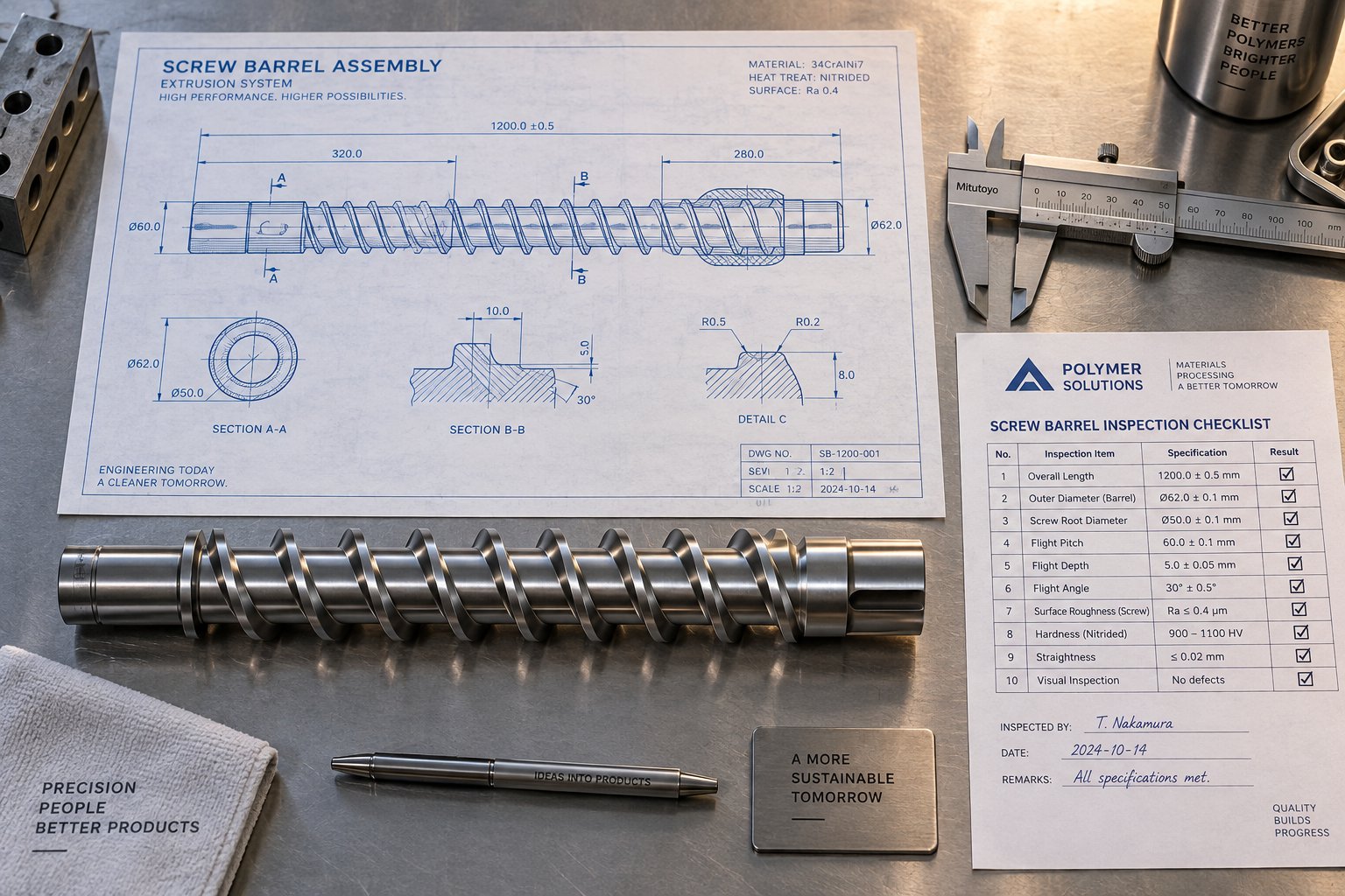
Whether you are duplicating the existing design or upgrading to better-suited metallurgy based on the wear patterns identified earlier, every replacement begins with a precise set of dimensional, geometric, and material parameters communicated clearly to the supplier. Think of this section as your translation layer — converting machine knowledge into a purchase specification that eliminates ambiguity.
Critical Dimensions and Geometry Parameters
Screw and barrel geometry governs how resin is conveyed, compressed, melted, and metered. Getting these numbers right ensures the replacement component delivers at least the same — and potentially better — performance as the original.
Start with the parameters that define fit:
- Overall length and outside diameter (OD). These are the non-negotiable physical envelope dimensions. A barrel that is 3 mm too long will not seat properly in the machine frame; a screw OD that exceeds the bore by even a few thousandths creates immediate interference.
- Inside diameter (ID) of the barrel bore. This sets the nominal screw size and must match within tight tolerance. Standard new-screw clearance falls between 0.005 and 0.010 inches (0.125 to 0.25 mm) per side, as Plastics Today notes — less for small-diameter machines, slightly more for large ones.
- L/D ratio. The length-to-diameter ratio — typically 24:1 for general-purpose extruders, ranging up to 30:1 or more for applications that demand extra melting, mixing, or venting capacity. A higher L/D gives the resin more residence time and shear history, which benefits difficult-to-melt polymers but can degrade heat-sensitive resins if not matched carefully.
- Compression ratio. This is the volume ratio of the first flight to the last, often approximated by the ratio of feed-zone channel depth to metering-zone channel depth. Most general-purpose screws fall between 2:1 and 4:1. A ratio that is too low for a given resin leads to poor melting and air entrapment; too high creates excessive shear heat and degradation risk. As screw design authority Allan Griff explains, compression ratio is a useful number, but it cannot properly describe a screw unless at least one channel depth is also known.
- Flight geometry. Pitch (the axial distance between adjacent flights), flight depth in each zone, flight width (typically around 10% of barrel diameter), and the number of flights all shape conveying and melting behavior. Square-pitch designs — where the pitch equals the diameter — remain the most common configuration, making it straightforward to estimate L/D by counting turns.
- Shank and drive-end configuration. The connection between the screw and the gearbox output shaft varies widely across OEMs. Splined shanks, keyed shanks, and proprietary drive-end profiles must match exactly, or the screw simply will not couple to the machine. Always measure or photograph the existing drive end rather than relying on memory.
- Heater band compatibility. The barrel's outer diameter and zone-break locations must align with existing heater bands, thermocouples, and cooling-fan placements. A barrel with zone lengths that differ from the original forces a full re-wiring of the heating system — an unnecessary cost if caught at the specification stage.
When you have a choice between simply duplicating the old component and making a performance upgrade, the parameters above become design levers rather than just reference numbers. For example, a plant switching from unfilled polypropylene to a 30% glass-filled nylon on a Davis Standard extruder might benefit from a deeper feed zone for improved solids conveying and a longer transition zone to handle the higher melting energy demand — changes that a knowledgeable supplier can recommend based on your resin family and throughput targets.
Use the following checklist when contacting any supplier to ensure no critical detail is missed:
- Machine make, model, and serial number
- Barrel overall length, outside diameter, and bore diameter
- Screw overall length, nominal diameter, and shank/drive-end configuration (drawing or photograph)
- L/D ratio and compression ratio (or feed, transition, and metering zone depths)
- Flight pitch, width, and number of flights
- Mixing-section type if applicable (Maddock, barrier, pin mixer)
- Metallurgy and surface treatment of the original component
- Desired metallurgy upgrade (if wear analysis justifies a change)
- Heater band zone lengths and thermocouple locations
- Resin types and filler content to be processed
- Target throughput rate and typical operating RPM range
Metallurgy and Surface Treatment Selection
Dimensions get the part into the machine. Metallurgy determines how long it stays there. Your earlier wear analysis — abrasive, adhesive, corrosive, or fatigue — directly dictates which base steel, surface treatment, and liner material belong on the replacement specification.
Standard nitrided barrels, with a case depth of roughly 0.45-0.7 mm and surface hardness around HV 850-1000, handle unfilled commodity resins well. Step up to glass-filled engineering plastics or mineral-loaded compounds, and bimetallic barrels become the better investment. Bimetallic linings with alloy hardness in the HRC 50-65 range and alloy depth of 0.8-2.0 mm can extend service life two to three times compared to nitrided alternatives in abrasive service — and while the initial cost runs roughly 25% higher, total cost of ownership over a three-year horizon can drop by approximately 50% thanks to fewer replacements and less unscheduled downtime.
For corrosive resins — PVC, fluoropolymers, flame-retardant compounds — nickel-based alloys or stainless-steel-lined bores resist chemical attack where iron-based metallurgies fail. On the screw side, flight-tip hardfacing with cobalt or nickel-tungsten alloys protects the highest-wear surfaces, while chrome plating the root and flanks improves resin release and corrosion resistance.
Communicating metallurgy requirements clearly to your supplier shortens the quotation cycle and eliminates back-and-forth. Factory-direct manufacturers like NANHAIYA, which serves plastic processors, equipment builders, and maintenance teams with custom and replacement screw barrels for both extrusion and injection molding, can simplify this conversation considerably. Working directly with the manufacturer's engineers means your wear data and resin profile translate into a material recommendation without passing through intermediary sales layers — reducing the risk of specification miscommunication that plagues multi-tier supply chains.
Specification Differences Across Machine Types
A screw barrel replacement for a single-screw extruder, a twin screw barrel for a compounding line, and an injection molding plasticating assembly share the same general parameter categories — but the priorities within those categories shift significantly. Overlooking these differences is a common ordering mistake, especially in facilities that run multiple machine types.
In single-screw extrusion, the screw design does the lion's share of melting and mixing work. L/D ratio, compression ratio, and barrier or mixing-section design dominate the specification because they directly control melt quality and output stability. Flight geometry decisions — whether to include a Maddock mixing section, barrier flights, or wave-screw elements — are process-critical choices that can dramatically improve performance when matched to the resin family.
Twin screw and barrel assemblies for co-rotating or counter-rotating twin-screw extruders introduce a different design vocabulary entirely. Instead of a single continuous screw, you are specifying modular screw elements — conveying elements, kneading blocks, and mixing discs — assembled on a splined shaft. The barrel segments are also modular, with individual heated and cooled sections, and include vent ports, side-feed openings, and vacuum connections. Wear patterns in twin-screw systems concentrate at kneading block tips and barrel bore transitions, making element-level replacement and bore-liner specifications the priority rather than whole-screw geometry.
Injection molding screws add yet another layer. The screw must not only plasticize resin but also function as a plunger during injection, which introduces axial load, check-ring wear, and shot-to-shot consistency as specification concerns. As industry data indicates, roughly 90% of injection molding machines use single-screw designs, but the screw geometry must be tuned more precisely to the specific resin: shallow flights for low-viscosity PP to prevent backflow, deeper flights for high-viscosity PC to ensure efficient material delivery, and flight-tip hardness ratings of HRC 60 or higher for glass-reinforced compounds.
The comparison table below highlights how specification priorities shift across these three machine categories:
| Specification Parameter | Single-Screw Extrusion | Twin-Screw Extrusion | Injection Molding |
|---|---|---|---|
| L/D Ratio | Primary performance driver (commonly 24:1 to 30:1+) | Defined by total barrel-segment count; modular design allows length changes | Typically 20:1 to 26:1; balanced against shot size and residence time |
| Compression Ratio | Critical — must match resin melt behavior (2:1 to 4:1 range) | Controlled by kneading-block and element sequencing rather than channel depth | Important for plasticating quality; tuned to resin viscosity and filler content |
| Flight / Element Geometry | Continuous flights; barrier, Maddock, or wave sections for mixing | Modular elements (conveying, kneading, mixing discs) assembled on splined shaft | Continuous flights; check ring and nozzle-seat geometry are additional concerns |
| Metallurgy Priority | Barrel liner and flight-tip hardness matched to filler abrasiveness | Kneading-block wear surfaces and barrel-segment liners are primary wear points | Flight-tip and check-ring hardness critical; corrosion resistance for engineering resins |
| Drive-End Configuration | OEM-specific shank; single drive coupling | Splined shafts for element stacking; torque rating per shaft is critical | Shank must handle both rotational and axial (injection) loads |
| Key Replacement Concern | Whole-screw and whole-barrel replacement or refurbishment | Element-level replacement; individual barrel-segment liners | Screw, barrel, check ring, and nozzle seat often replaced as a system |
Getting the specification right eliminates the most frustrating delays in the replacement process — parts that arrive and do not fit, metallurgy that does not match the application, or geometry that underperforms the old design. For multi-machine facilities, consolidating your specifications through a single factory-direct source reduces qualification effort and ensures consistent quality across orders. Manufacturers like NANHAIYA that cover both extrusion and injection molding product lines allow maintenance teams to standardize their sourcing, simplify engineering communication, and maintain traceability from raw steel through finished component — advantages that compound with every replacement cycle.
With the right specification locked down and a supplier aligned, the focus shifts to the physical work itself: safely removing the worn components, installing the new ones without damaging them, and bringing the machine back online with confidence.
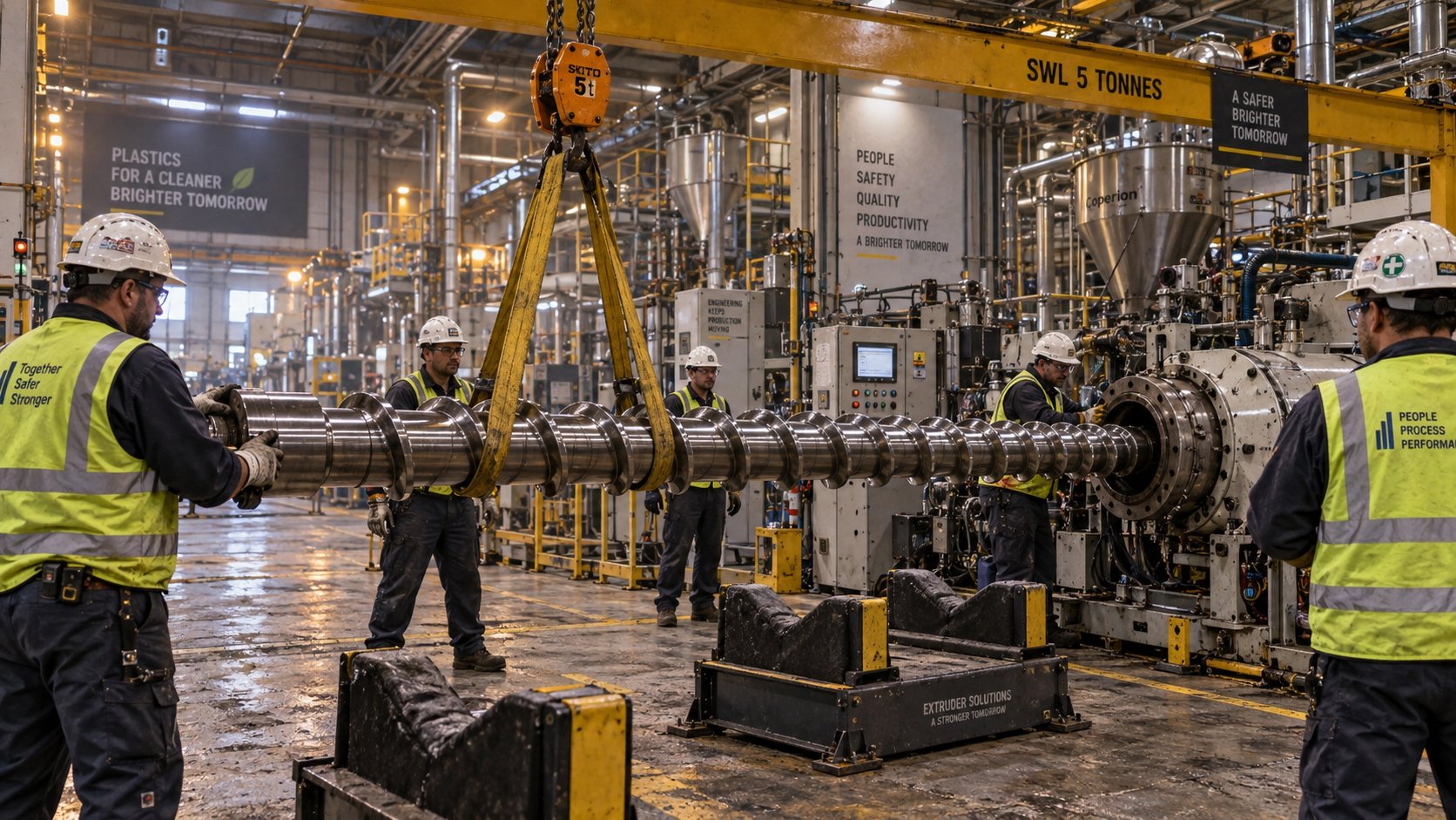
Step-by-Step Screw Barrel Replacement Procedure
Specifications are on the purchase order. The new components have arrived, been inspected, and match your documentation. The only thing standing between a worn-out screw extruder assembly and restored production is the physical swap itself — and this is exactly where avoidable mistakes happen most often. A misaligned barrel forced into position, a cold start that warps a brand-new bore, or a seized screw yanked out with a forklift can turn a planned maintenance event into an equipment catastrophe.
The procedure below applies broadly to single-screw extrusion and injection molding machines. Twin-screw systems share the same safety framework but introduce additional phasing, element-sequencing, and synchronized support requirements covered briefly at the end. Regardless of machine type, treat every step as a quality gate — rushing through one to save twenty minutes can cost you the full value of the new component.
Pre-Replacement Safety and Preparation Steps
Every screw barrel replacement begins long before anyone touches a wrench. The preparation phase protects people first and equipment second.
Never rely on an emergency stop alone during a screw barrel swap — heaters and hydraulic pressure can remain active even when the drive is off. Full energy isolation under your plant's lockout/tagout procedure is non-negotiable.
Start by purging the barrel while the screw can still rotate. Select a purge compound or transition resin compatible with the production material and processing temperature range — PVC, engineering plastics, and highly filled compounds each demand different purge strategies. The goal is to evacuate as much residual polymer as possible before shutdown, because cooled resin locks screws in place and dramatically increases extraction difficulty.
With the barrel purged, shut down the drive and execute a full lockout/tagout covering electrical, hydraulic, pneumatic, and thermal energy sources. Verify a zero-energy state before proceeding. Workers should don heat-resistant gloves, steel-toed boots, and eye protection rated to ANSI Z87.1 — molten polymer splashes and hot metal surfaces remain hazards well after the machine stops running.
While the machine cools to a safe handling temperature, gather everything you will need: wrenches and torque tools sized for your barrel bolts, a calibrated torque wrench, brass scrapers and copper brushes for cleaning, an approved hoist or overhead crane with rated lifting straps, padded V-blocks or screw stands, alignment markers, and your bore gauge and micrometer set for baseline measurements of the new components. Having these staged and ready prevents mid-procedure delays that extend exposure time near hot equipment.
Finally, review the manufacturer's manual for your specific machine. Torque specifications, disassembly sequences, and alignment tolerances vary across OEMs — assuming one machine's procedure applies to another is a common source of installation errors.
Screw Extraction and Barrel Removal Procedure
With energy isolated and the workspace prepared, follow this sequence to remove the old components safely:
- Remove covers, guards, and front-end components. Take off all protective covers and barrel guards. Remove the die head, adapter, breaker plate, and any tooling blocking the screw's extraction path. Protect exposed thermocouple wires, threads, and sealing surfaces as you work. Label and store all fasteners in a marked container — you will thank yourself during reassembly.
- Disconnect heater bands and thermocouples. Loosen and slide heater bands off the extrusion barrel carefully. Disconnect each thermocouple and electrical lead, labeling every wire with its zone number and position. Photographs of the wiring layout before disconnection serve as an invaluable reassembly reference.
- Unbolt and support the barrel assembly. Locate and remove the bolts securing the barrel to the machine frame. The barrel is heavy — always support it with a hoist, crane, or sturdy stands before removing the final fasteners. Never allow the barrel's full weight to hang unsupported from the feed-section connection.
- Disconnect the screw drive end. Remove the gearbox coupling, retaining nut, spline key, cooling union, and any other drive-end hardware per the machine manual. Mark the original positions and photograph the sequence before disassembly. Confirm no retainer or cooling connection remains before applying extraction force.
- Extract the screw. The preferred method is to push the screw out through the discharge end using controlled axial force — either the machine's built-in extraction system or a hydraulic screw puller. Apply force gradually along the screw centerline. Place padded supports beneath the screw as each section emerges, keeping it level with the barrel bore to prevent bending. Never hammer, pry, or push the screw with a forklift — these methods damage flight crests, score the barrel bore, and can wreck gearbox alignment.
- Handle a seized screw. If the screw resists extraction, stop and diagnose before increasing force. Common causes include cold polymer, carbon buildup, abrasive filler deposits, or a hidden retaining fastener. Warm the barrel gradually using the installed heaters — never an open flame — and allow heat to soak evenly before re-applying moderate axial pressure. If force rises sharply, metal scraping sounds appear, or the screw begins to bend, stop immediately. Forcing a stuck screw risks barrel bore damage that turns a component replacement into a machine rebuild.
- Remove the barrel. With the screw extracted and set on padded V-blocks, slide the barrel away from the machine using the hoist. Clean all mounting surfaces on the machine frame with brushes and cloths, removing debris, old lubricant, and any corrosion. Inspect the mounting area, feed throat, and gearbox output for wear or damage — any issues found here must be corrected before installing the new barrel.
For a screw plastic extruder with a long barrel, you will need several support points along the extraction path. Long screws sag under their own weight, and an unsupported flight crest resting on concrete or steel creates an instant nick that compromises performance from the very first revolution.
Installing the New Screw Barrel and Initial Startup
Installation is where the most expensive mistakes happen — because they happen to brand-new parts. Three errors account for the majority of premature component damage during installation:
- Misalignment forcing. Sliding a new barrel into position and tightening bolts before verifying centerline alignment with the gearbox and feed section can impose bending stresses that accelerate wear from day one. The total out-of-alignment error must remain less than half the clearance between the screw flight tip and barrel bore. Use dial indicators or laser alignment tools to confirm before torquing fasteners.
- Cold-starting without a heat soak. Energizing the drive before the barrel reaches processing temperature forces the screw to rotate against solidified resin — essentially grinding new metal surfaces against a plug of cold plastic. Always bring the barrel up to its full temperature profile and hold it there for a minimum soak period (consult the OEM manual, but 20-30 minutes is a common guideline) before engaging the drive.
- Skipping thrust bearing inspection. Installing a factory-new screw into a machine with a worn thrust bearing recreates the axial float problem that may have contributed to the old screw's demise. Check the bearing for play and replace it if needed — this small investment protects the far larger one you just made in new plasticating components.
With those pitfalls in mind, follow this installation sequence:
- Install the new barrel. Slide the barrel into position using the hoist, aligning it carefully with the machine frame, feed throat, and gearbox housing. Insert and hand-tighten mounting bolts, then verify alignment before applying final torque. Use a calibrated torque wrench and follow a star or cross tightening pattern to distribute clamping force evenly — over-torquing distorts the bore, while under-torquing allows movement during operation.
- Insert the new screw. Coat the screw lightly with a compatible anti-seize or assembly lubricant recommended by the manufacturer. Slide it into the barrel from the feed or discharge end (per OEM instructions), supporting its weight along the full length. Engage the drive-end coupling, reinstall the retaining hardware, and verify that the screw rotates freely by hand without binding.
- Reconnect heater bands, thermocouples, and guards. Reinstall heater bands in their correct zone positions, ensuring full contact with the barrel surface — poor contact creates hot spots that mimic process problems and shorten band life. Reconnect thermocouples to their labeled zones, double-checking each connection for a secure fit. Reinstall all guards and protective covers.
- Heat soak and verify temperature profiles. Power up the heating system and bring all zones to their target setpoints. Allow the barrel to soak at temperature until readings stabilize. Verify that each zone holds its setpoint without excessive overshoot or oscillation — anomalies here point to wiring errors or damaged heater bands.
- Perform a controlled startup. Engage the drive at low RPM with no material in the hopper. Listen for unusual noises — scraping, knocking, or vibration — that indicate misalignment or contact. If the machine sounds clean, introduce material gradually and monitor torque, melt pressure, and discharge temperature as throughput increases toward the normal operating range.
- Run test product and inspect. Produce a short run of parts or extrudate and check for dimensional consistency, surface quality, and absence of defects. Compare melt temperature and output rate to historical baselines. These initial readings become your post-replacement reference point for future wear monitoring.
Twin-screw systems add complexity at several of these stages. Both screws must maintain correct phase alignment and intermeshing orientation throughout extraction and reinsertion — rotating or pulling one independently risks damaging intermeshing flight geometry. Modular barrel segments are removed and installed individually, with each segment's liner condition and O-ring seals verified before reassembly. The core safety principles remain identical, but the sequencing demands closer attention to the machine manual's specific twin-screw procedure.
A successful physical installation, however, is only the starting line. The real proof comes from validating that the new components actually deliver the performance improvements your data predicted — and from building the monitoring schedule that ensures you catch the next wear cycle early rather than late.
Post-Replacement Validation and Maintenance Planning
The new injection screw is turning, the barrel zones have stabilized, and the first extrudate or molded parts look clean. It is tempting to call the job done, hand the machine back to production, and move on. That temptation is exactly how plants lose the advantage a fresh screw barrel replacement should deliver. Without a structured validation step and a forward-looking inspection schedule, you have no baseline to measure future wear against — and no early warning system to prevent the next swap from becoming another emergency.
Validating Performance After Replacement
Validation answers a simple question: did the replacement actually restore the performance your wear data said was missing? Gut feel will not cut it here. You need numbers recorded under controlled conditions within the first hours of production — numbers that become the reference point for every future inspection.
Start with the mechanical baseline. Using the same bore gauge and micrometer procedures described earlier, measure the new barrel bore ID and injection molding feedscrew flight OD at the same axial stations you used during your pre-replacement inspection. Record the initial diametral clearances. These readings represent your "time zero" — the tightest clearances the components will ever have — and every future measurement will be compared against them.
Then capture the process baseline. Run the machine at your standard operating conditions — the same RPM, temperature profile, and resin that the line was processing before the old components were pulled. Record melt temperature at the discharge, head pressure, motor load or torque draw, and throughput rate in kg/h or lb/h. Compare these values to your historical data. You should see melt temperature drop back toward its original range, output recover at the same or lower screw speed, and energy consumption per kilogram decrease — all direct consequences of restored pumping efficiency.
Finally, validate product quality. Run test parts or a short production sample and measure dimensional consistency (part weight, wall thickness, or gauge), surface quality, and absence of defects like unmelts, gel streaks, or burn marks. For injection molding screws, shot-to-shot weight variation is the most sensitive indicator — it should tighten immediately with new clearances and a fresh check ring.
Use this checklist to confirm nothing gets overlooked during the validation window:
- Record new barrel bore ID and screw flight OD at each measurement station
- Calculate and document initial diametral clearance at every station
- Log melt temperature at discharge under standard operating conditions
- Confirm output rate recovery at the same RPM as pre-replacement baseline
- Record motor load, torque draw, and head pressure at standard rate
- Run test parts and measure dimensional consistency (weight, thickness, gauge)
- Inspect product surface quality for defects, streaks, or discoloration
- Verify all barrel zone temperatures hold setpoints without excessive override
- Confirm no unusual noise, vibration, or torque spikes during operation
If any metric falls short of expectations — output does not recover, melt temperature stays elevated, or part quality does not improve — do not assume the new components are defective. Revisit the upstream and downstream checklist from earlier in this guide: feed throat condition, heater band contact, thermocouple accuracy, thrust bearing play, and screen pack loading can all mask or offset the gains a new screw and barrel should deliver.
Building a Proactive Wear-Monitoring Schedule
Your validation data is the first point on a wear-rate trend chart — and maintaining that chart is the single most valuable habit a maintenance team can adopt. Periodic measurements plotted against machine hours reveal the slope of wear progression, and that slope tells you when clearance will reach your action threshold months before symptoms appear on the production floor.
The concept is straightforward. At each scheduled inspection, measure barrel bore ID and injection screw flight OD at the same axial stations. Calculate diametral clearance, plot it on a chart with cumulative operating hours on the x-axis, and connect the dots. A steeper slope means faster wear. A sudden change in slope signals that something in the process has shifted — a new filler, a resin lot with higher contamination, or a mechanical issue like misalignment developing. As industry best practice recommends, repeating measurements at the same locations allows maintenance teams to calculate wear rate and plan the next inspection before performance becomes critical.
How often should you inspect? There is no universal interval — it depends on three variables:
- Resin abrasiveness and corrosiveness. Lines running glass-filled nylons, mineral-loaded compounds, or corrosive PVC should be inspected every 2,000-3,000 operating hours — roughly quarterly on a two-shift schedule. Unfilled polyolefins and general-purpose polystyrene wear components far more slowly, making semi-annual or annual inspections a reasonable starting point.
- Historical wear rate. Once you have two or three data points on the trend chart, let the data drive the interval. If clearance is growing 0.02 mm per 1,000 hours, you can calculate exactly how many hours remain before reaching the medium or high wear threshold — and schedule the next measurement accordingly.
- Production criticality. A line feeding a 24/7 automotive or medical production schedule carries far more downtime cost than a secondary line running intermittent commodity jobs. High-criticality lines justify tighter inspection intervals regardless of resin type because the cost of a surprise failure dwarfs the cost of an extra measurement event.
A practical framework, adapted from guidance published by Reiloy USA's preventive maintenance handbook, recommends inspecting every six months when running reinforced resins until wear trends are established, and annually for unfilled materials. Shorten the interval whenever the trend chart shows acceleration.
Documenting Replacement History for Future Planning
Measurements and trend charts protect the current replacement cycle. A complete replacement history protects every cycle that follows. Each time a screw or barrel is replaced, repaired, or refurbished, record the following details in a centralized maintenance log — whether that is a CMMS system, a dedicated spreadsheet, or even a well-organized paper file:
- Machine ID, make, model, and serial number
- Component serial number and supplier name
- Date of installation and machine hours at installation
- Measured initial clearances at all inspection stations
- Metallurgy and surface treatment of the installed component
- Resin types and filler content processed on this machine
- Reason for replacement (wear data, failure mode, or upgrade)
- Warranty terms and expiration date
- Cost of the component and any associated labor
This record serves multiple purposes. It establishes warranty traceability — if a component fails prematurely, having the installation date, initial clearance data, and operating conditions documented strengthens your claim. It feeds long-term cost-of-ownership analysis, letting you compare the actual service life of different metallurgies, suppliers, or design modifications. And it builds institutional knowledge that survives staff turnover, ensuring the next maintenance manager inherits data rather than guesswork.
Treating post-replacement validation and wear monitoring as permanent disciplines — not one-time tasks — transforms screw barrel replacement from a reactive expense into a predictable, budgetable maintenance event. The data you collect after every installation feeds directly into the next replace-versus-repair decision, the next specification, and the next supplier conversation. That closed loop is what separates plants that manage their plasticating components strategically from those that simply react when the machine forces their hand.
Turning Screw Barrel Replacement into a Strategic Advantage
Every chapter in this playbook reinforces one principle: the plants that treat an extruder screw barrel swap as a managed lifecycle event — rather than a fire drill — spend less, produce better product, and suffer fewer surprises. The data loop is straightforward. Watch for symptoms. Measure clearances. Let the numbers drive the replace-versus-repair decision. Translate that decision into a precise specification. Execute the physical work without damaging new components. Validate results against a documented baseline. Then keep measuring so the next cycle starts from knowledge, not panic.
The Complete Replacement Lifecycle at a Glance
Whether you are a technician responsible for pulling a worn barrel screw assembly or a maintenance manager defending a capital request, this checklist captures the critical actions from each stage of the process:
- Monitor machine symptoms continuously — declining output, rising melt temperature, inconsistent part weight, and excessive zone overrides are early signals, not background noise.
- Rule out ancillary causes first — verify heater bands, thermocouples, feed throat, thrust bearings, and screen packs before attributing problems to the screw or barrel.
- Measure with bore gauges and micrometers at defined intervals — log every reading with date, axial location, and machine hours to build a wear-rate trend.
- Decide data-driven — compare remaining wall thickness, wear distribution, metallurgical condition, and cost-to-life ratios across replace, repair, refurbish, and re-nitride options.
- Specify with precision — document every dimension, geometry parameter, metallurgy requirement, and drive-end configuration before contacting a supplier.
- Execute safely and methodically — follow lockout/tagout, verify alignment, heat-soak before startup, and inspect thrust bearings before installing a new plastic extruder screw.
- Validate immediately after startup — baseline new clearances, confirm output recovery, and run test parts to establish the reference point for all future inspections.
- Plan proactively — plot wear trends, set inspection intervals based on resin abrasiveness and line criticality, and document every replacement for warranty and cost-of-ownership tracking.
When screw barrel replacement becomes a planned lifecycle discipline instead of an emergency reaction, it stops being a cost center and starts functioning as a quality and productivity investment — one that pays dividends in lower scrap, reduced energy consumption, and predictable maintenance budgets.
Choosing a Reliable Screw Barrel Supplier
The best measurement program and decision framework still depend on one practical reality: receiving the right component, built to your exact specification, within a lead time that fits your maintenance window. Supplier selection deserves the same rigor you apply to the technical work. Look for manufacturers who control their own metallurgy, heat treatment, and machining — that traceability from raw steel to finished bore protects you when questions arise about premature wear or warranty claims.
Factory-direct sourcing eliminates the communication layers that introduce specification errors. NANHAIYA is one such resource, providing plastic processors, equipment builders, and maintenance teams with custom and replacement screw barrels for both extrusion and injection molding applications. Working directly with their engineering team means your wear data, resin profile, and machine dimensions translate into a finished component without passing through intermediary interpretations — shortening lead times and ensuring the metallurgical traceability that this entire playbook has emphasized.
Screw barrel replacement will always be part of plastics processing. The only variable is whether you manage it — or it manages you. Invest in the measurement discipline, build the documentation habit, and choose suppliers who treat your specifications as seriously as you do. That combination turns a routine maintenance event into a genuine competitive advantage.
Frequently Asked Questions About Screw Barrel Replacement
1. How do I know when my extruder screw and barrel need replacing?
Key warning signs include declining output at constant RPM, rising melt temperatures without setpoint changes, inconsistent part weight or wall thickness, increased scrap or burn marks, and visible unmelts in finished products. Before attributing these symptoms to the screw and barrel, rule out ancillary issues such as worn feed throats, faulty thermocouples, damaged heater bands, and clogged screen packs. Confirm wear by measuring diametral clearance with bore gauges and micrometers — once clearance exceeds OEM-recommended thresholds, replacement or repair should be planned promptly.
2. What is the difference between replacing, repairing, and refurbishing a screw barrel?
Full replacement involves ordering a brand-new screw, barrel, or both to OEM or upgraded specifications, providing factory-new dimensions and maximum service life. Repair targets localized damage through weld buildup (such as PTA welding) and precision regrinding of specific zones, costing roughly 30-50% of a new part. Refurbishment restores a structurally sound component across its full length via boring, honing, re-chroming, or re-coating, typically running 40-60% of new-part cost. Re-nitriding is the lightest option, refreshing surface hardness on components with minimal dimensional wear at 15-30% of replacement cost. The right choice depends on remaining wall thickness, wear distribution, metallurgical condition, and production urgency.
3. How often should screw and barrel wear be measured?
Measurement frequency depends on resin abrasiveness, historical wear rate, and production criticality. Lines processing glass-filled nylons, mineral-loaded compounds, or corrosive PVC benefit from inspections every 2,000-3,000 operating hours — roughly quarterly on a two-shift schedule. Unfilled polyolefins and general-purpose polystyrene wear components more slowly, making semi-annual or annual inspections reasonable. High-criticality production lines justify tighter intervals regardless of resin type. Once you have two or three data points on a wear-rate trend chart, let the measured slope of clearance growth determine when to schedule the next inspection.
4. What specifications do I need when ordering a replacement screw barrel?
Provide the machine make, model, and serial number along with barrel overall length, outside diameter, and bore diameter. Include screw overall length, nominal diameter, shank or drive-end configuration (ideally a drawing or photograph), L/D ratio, compression ratio, flight pitch, width, number of flights, and any mixing-section details. Specify the original metallurgy and any desired upgrade based on your wear analysis, heater band zone lengths, thermocouple locations, resin types being processed, and target throughput. Factory-direct suppliers like NANHAIYA (nhyscrews.com/products) streamline this process by letting you work directly with manufacturing engineers who translate your wear data and resin profile into the correct material and geometry recommendation.
5. What are common mistakes to avoid during screw barrel installation?
Three errors cause the most premature damage to new components. First, forcing a misaligned barrel into position imposes bending stresses that accelerate wear from day one — always verify centerline alignment with dial indicators or laser tools before torquing fasteners. Second, cold-starting the machine without a proper heat soak forces the screw to rotate against solidified resin, grinding new metal surfaces against a plug of cold plastic. Allow the barrel to reach full processing temperature and soak for at least 20-30 minutes before engaging the drive. Third, skipping thrust bearing inspection before installing a new screw recreates the axial float that may have worn out the previous component.
Written by
Nanhaiya Technical Team
Zhoushan Nanhaiya Plastic Machinery Co., Ltd.
The Nanhaiya technical team supports screw and barrel manufacturing projects through application review, technical communication, custom manufacturing coordination, and production and quality control.
Discuss Your Application
Related Articles
More insights on screw barrel technology and plastics processing.

What Nobody Tells You About Screw Barrel For Plastic Machine Design
Oct 10, 2026
Learn how screw barrel for plastic machine design affects melt quality, throughput, and wear life. Covers geometry, resin matching, troubleshooting, and sourcing.
Read Article
Single Screw Extruder for Sheet: Stop Guessing, Start Specifying
Oct 9, 2026
Learn how to specify a single screw extruder for sheet production. Covers screw geometry, resin-specific processing, troubleshooting, and maintenance best practices.
Read Article
PE Pipe Extruder Machine: What Datasheets Won't Tell You
Oct 9, 2026
Learn how a PE pipe extruder machine works, key specs explained, material grade selection, maintenance tips, and buyer guidance beyond the datasheet.
Read ArticleLooking for something else?
Search by material, symptom or product and jump straight to the relevant page.
These are navigation suggestions based on keyword matching — not a quotation, not a delivery commitment, and not a substitute for engineering review. Final specification is confirmed by our engineers against your drawings and processed material.
Need help with screw barrel selection?
Share your machine model, processed material and application. Our team can help with pricing and technical support.