

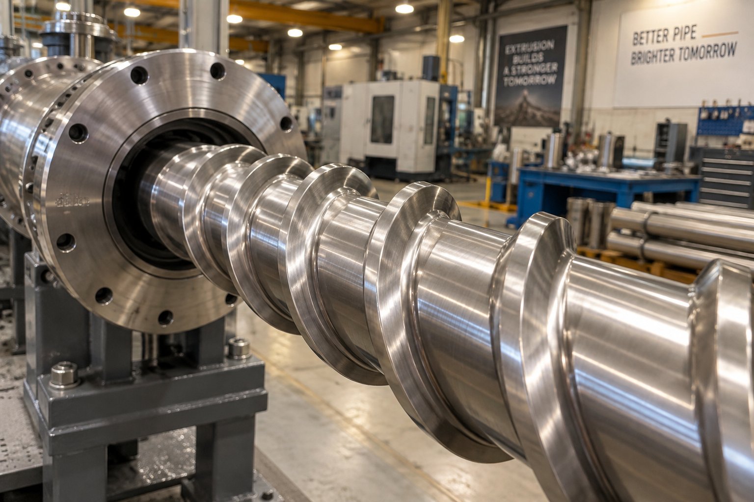
What Is a Screw Barrel for HDPE Pipe Extrusion
Imagine feeding raw plastic pellets into one end of a machine and pulling out a perfectly formed, pressure-rated pipe from the other. The component that makes that transformation possible is the screw barrel — and when the polymer in question is HDPE, getting its design right becomes far more critical than most equipment catalogs suggest.
A screw barrel for HDPE pipe extrusion is the central processing assembly of a plastic extrusion line. It consists of a helical-flighted rotating screw housed inside a heated cylindrical barrel. Together, they melt, mix, pressurize, and convey high-density polyethylene resin into a continuous, uniform melt stream that is shaped into pipe by a downstream die head.
Every stage of pipe formation — wall thickness consistency, surface smoothness, pressure rating — traces back to how well the extruder screw barrel handles the resin before it ever reaches the die. That makes the screw and barrel the single most influential hardware choice on your entire extrusion line.
What a Screw Barrel Does in HDPE Pipe Extrusion
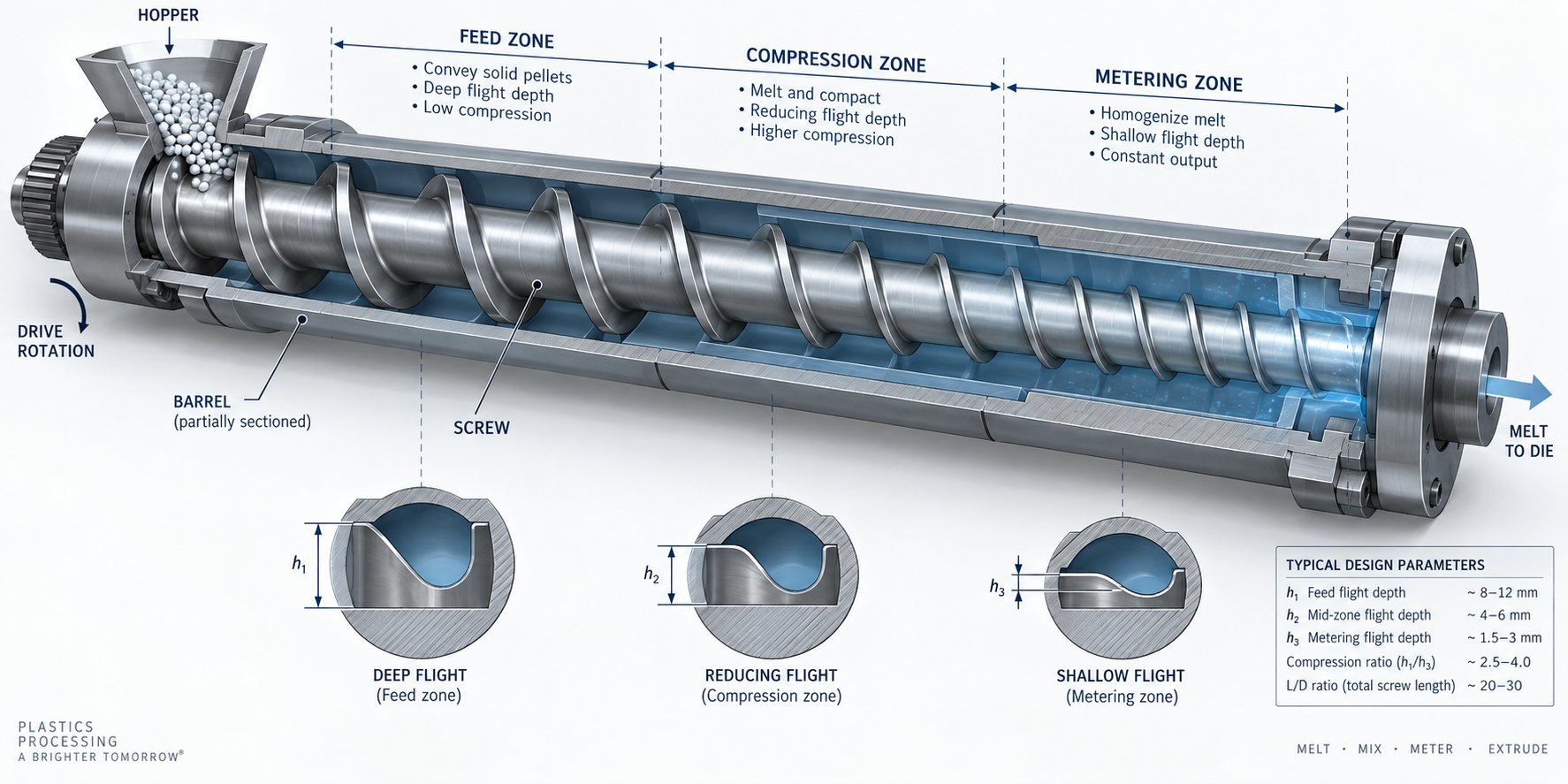
At a high level, the screw barrel performs three jobs simultaneously. First, it accepts solid HDPE pellets from a hopper and conveys them forward through friction and drag forces. Second, it converts those pellets into a homogeneous molten state using a combination of conducted heat from barrel heaters and frictional (shear) heat generated by the rotating screw. Third, it meters that melt at stable pressure and temperature so the die head can produce a pipe with consistent dimensions.
These functions happen across distinct zones along the screw's length — feed, compression, and metering — each engineered with different flight depths and geometries. The structure and parameters of the screw directly influence plasticization quality, throughput rate, and energy efficiency. Barrel temperature profiles, typically ranging from 150-180 degrees Celsius at the feed end up to 210-230 degrees Celsius at the metering section, must complement the screw geometry to avoid both under-melting and thermal degradation.
Why Generic Screw Barrels Fall Short for HDPE
Here is where most general-purpose extruder screws and barrels run into trouble. HDPE is a semi-crystalline polymer, which means its molecular chains pack tightly into ordered crystal structures. Melting those crystals demands a significant energy input — known as the heat of fusion — that amorphous plastics simply do not require. On top of that, HDPE exhibits high melt viscosity. It resists flow even after melting, placing heavy demands on screw geometry to generate adequate pressure without overheating the resin.
The processing window is narrow, too. Push barrel temperatures too high or allow excessive shear, and you risk thermal degradation — chain scission that weakens the finished pipe. Run too conservatively, and unmelted particles called "gels" end up embedded in the pipe wall, creating weak points that can fail under pressure. As NC State Extension research on screw profile design underscores, a shear-sensitive material often fails to form a stable product when processed with a mismatched screw configuration.
A generic all-purpose screw barrel simply cannot balance these competing demands. Feed zone depth, compression ratio, and metering channel precision all need to be calibrated specifically for HDPE's melt behavior. This guide is built for processors, plant engineers, and procurement professionals who need to understand exactly how those calibrations work — and where the overlooked design gaps can quietly erode pipe quality, throughput, and profitability.
The starting point for any informed specification decision is a clear understanding of the material properties driving these requirements — properties that dictate every dimension of the screw geometry itself.
Why HDPE Demands Specialized Screw Barrel Geometry
HDPE does not behave like most other plastics inside an extruder. Its molecular architecture creates a unique set of processing challenges, and each one leaves a fingerprint on how the extrusion screw barrel must be designed. Ignore these material-level realities, and you end up chasing pipe defects that no amount of temperature adjustment or line speed tweaking will fix.
HDPE Material Properties That Drive Screw Design
Picture the molecular chains inside an HDPE pellet. Unlike amorphous polymers such as polystyrene — where chains tangle randomly like a bowl of spaghetti — HDPE is semi-crystalline. Its linear, low-branching chains fold into tightly packed crystalline regions interspersed with disordered amorphous zones. This ordered structure gives HDPE its excellent strength and chemical resistance, but it also means you need significantly more energy to break those crystal lattices apart during melting. That extra energy demand is called the heat of fusion, and for HDPE it is substantially higher than for amorphous resins processed at similar temperatures.
In practical terms, a screw and barrel extruder running HDPE must deliver more thermal and mechanical energy per kilogram of resin than one running polystyrene or ABS. If the feed zone is too shallow, pellets compact prematurely and starve the compression zone. If compression is too aggressive, the sudden channel depth reduction generates excessive frictional heat — pushing the melt past its degradation threshold before the crystals have fully dissolved.
HDPE's high melt viscosity compounds this challenge. Even after melting, the polymer resists flow far more than lower-viscosity materials like LDPE. That viscous resistance raises internal shear stresses, which in turn generate more heat. The result is a feedback loop: higher viscosity creates more shear heating, which can push the melt temperature into a range where chain scission — the literal breaking of polymer chains — begins to occur. Chain scission weakens the finished pipe's long-term pressure rating, sometimes invisibly.
There is also HDPE's sensitivity to residence time. Spend too long at elevated temperatures inside the barrel, and oxidative degradation accelerates. A groove feed screw barrel configuration, commonly specified for HDPE, helps address part of this problem by increasing solids conveying efficiency in the feed zone so the resin moves through the system faster at any given screw speed. However, that faster conveyance demands matching adjustments in the compression and metering zones downstream — a design interplay that generic screws rarely accommodate.
All of these properties — high heat of fusion, high melt viscosity, shear sensitivity, and residence-time sensitivity — converge to create a narrow processing corridor. The screw geometry has to thread the needle between delivering enough energy to fully melt every pellet and avoiding the thermal overshoot that degrades the polymer. Feed zone depth, compression ratio, and metering zone channel dimensions each play a distinct role in maintaining that balance.
Essential Technical Terms Defined
Before diving into zone-by-zone design specifics, you will encounter several engineering terms repeatedly. Here is a plain-language glossary to keep as a reference:
- L/D Ratio (Length-to-Diameter Ratio): The functional length of the screw divided by its outer diameter. A common L/D for HDPE pipe extrusion falls between 24:1 and 33:1. As extrusion specialist Allan Griff notes, more length may mean more output when heating, melting, or mixing are the limiting factors. Higher ratios give the resin more time and barrel surface area for heat transfer and homogenization.
- Compression Ratio: The ratio of the channel volume in the first flight of the feed zone to the channel volume in the last flight of the metering zone. For constant-pitch screws, it is often simplified to the ratio of feed depth to metering depth. Typical values for HDPE range from about 2.5:1 to 4:1. This ratio controls how aggressively the resin is compacted and melted as it moves forward.
- Flight Depth (Channel Depth): The distance from the screw root to the top of the flight. Deep channels in the feed zone allow efficient intake of bulky pellets, while shallow channels in the metering zone create the high pressure needed for uniform die filling. Flight width — the thickness of the flight itself — is typically around 10% of barrel diameter.
- Helix Angle: The angle of the screw flight relative to a plane perpendicular to the screw axis. Most standard screws use a square pitch, meaning the distance from one flight to the next equals the screw diameter, producing a helix angle near 17.66 degrees. Adjusting this angle changes how quickly material advances per revolution.
- Shear Rate: A measure of how rapidly layers of melt slide past one another inside the screw channel. Higher screw speeds and shallower channels increase shear rate. For HDPE, excessive shear rate generates destructive heat, while insufficient shear rate leaves the melt poorly mixed and thermally inconsistent.
- Clearance (Screw-to-Barrel Gap): The gap between the outer edge of the screw flight and the inner barrel wall. On new screws, this clearance typically measures between 0.005 and 0.010 inches (0.125 to 0.25 mm). Too tight increases frictional heat and manufacturing cost; too loose allows backflow (leakage flow) that reduces pumping efficiency and melt consistency.
These parameters do not operate in isolation. Changing the L/D ratio, for instance, shifts how much melting can occur before the resin enters the metering zone, which in turn affects the compression ratio needed to avoid unmelted gels. Similarly, the clearance between screw and barrel directly influences leakage flow, which interacts with metering zone depth to determine output stability. Understanding these interdependencies is what separates a well-specified extrusion screw barrel from a catalog part that merely fits the machine.
With these definitions in hand, the logical next step is to see exactly how each screw zone applies them — from the moment pellets drop into the feed throat to the instant homogeneous melt exits toward the die.
Screw Zones Explained From Feed to Metering
Drop a handful of HDPE pellets into your palm. They are hard, slippery, and cool — about as far from a molten, pressure-ready melt stream as you can get. Transforming those pellets into a flawless pipe wall happens across three carefully sequenced zones inside the extruder screw and barrel, each with a distinct geometry and a distinct job. Get any single zone wrong, and the other two cannot compensate. Here is how each one works, what design choices matter most for HDPE, and where the hidden trade-offs live.
- Feed Zone — Solids Intake and Conveying
- Compression (Transition) Zone — Melting and Compaction
- Metering Zone — Pressure Stabilization and Output
Feed Zone Design for HDPE Solids Conveying
The feed zone is where raw pellets enter the screw channel from the hopper throat. Its primary job is deceptively simple: grab the pellets and push them forward as fast and as consistently as possible. The geometry that accomplishes this features deep, constant-depth flights — deep enough to accept a full bed of bulky HDPE pellets without bridging or starving the downstream zones.
Why does depth matter so much? HDPE pellets are slippery. Their low coefficient of friction against polished steel makes it easy for pellets to spin in place rather than advance. A deeper channel increases the volume of material in contact with the barrel wall, which is the primary friction surface responsible for dragging solids forward. As Allan Griff's extrusion fundamentals guide explains, the frictional forces between the barrel and the solid bed create forward conveying — a higher frictional force means more efficient solids transport.
For HDPE specifically, many modern barrel screw extruder setups go a step further by using a grooved feed section. Instead of a smooth bore, the barrel's inner wall in the feed zone features machined axial or helical grooves, housed within a separately water-cooled jacket. These grooves mechanically lock the pellets against the barrel wall, dramatically increasing the friction-driven conveying force. The payoff is substantial. Case studies comparing groove feed versus smooth bore extruders processing high-viscosity HDPE showed that a smaller 90 mm groove feed extruder matched the output of a larger 114 mm smooth bore machine — while achieving lower melt temperatures and reduced energy consumption.
There is an important catch, though. A grooved feed section pushes solids forward so aggressively that it fundamentally changes the pressure profile along the entire screw. The downstream compression and metering zones must be re-engineered to handle the higher solids conveying rate. As the same case study data indicates, groove feed designs typically require a shallower feed zone depth and a deeper metering zone compared to smooth bore screws — sometimes with little to no traditional compression at all. Pair a grooved barrel with a standard screw and barrel designed for smooth bore operation, and you risk surging, excessive pressure spikes, or premature wear.
Compression Zone and Melt Quality
Once the solid bed advances past the feed zone, it enters the compression — or transition — zone. Here, the channel depth gradually decreases, squeezing the pellets tighter against each other and against the barrel wall. This controlled reduction in volume does two things simultaneously: it forces trapped air backward toward the feed throat (preventing voids in the finished pipe), and it generates the frictional and conducted heat needed to melt those tightly packed crystalline structures.
For HDPE, the rate of this compression is critical. Imagine tightening a vise slowly versus slamming it shut. An overly aggressive compression — where the channel depth drops too quickly over too few screw turns — creates a sudden spike in shear heating. HDPE's high melt viscosity amplifies this effect, because a viscous material generates more frictional heat per unit of deformation than a low-viscosity one. The result? Localized hot spots where the melt temperature overshoots the safe processing window, triggering chain scission and thermal degradation that silently weakens the pipe's long-term pressure rating.
Swing too far in the other direction, and the compression is too gradual. The solid bed never fully consolidates before entering the metering zone. Unmelted particles — commonly called gels — survive the transition and end up embedded in the pipe wall. These gels act as stress concentrators under internal pressure, creating potential failure points that no amount of downstream cooling or calibration can fix.
The practical sweet spot for HDPE pipe extrusion typically involves a moderate compression ratio — often in the range of 2.5:1 to 4:1 — spread over a compression zone that occupies roughly 25% to 30% of the screw's functional length. This gives the high heat of fusion enough time and mechanical work to fully convert every crystalline domain into melt, without the thermal violence of a short, steep transition.
Optional barrier flights can further improve melt quality in this zone. A barrier screw introduces a secondary flight that separates the remaining solid bed from the already-molten polymer. Melt formed in the solids channel flows over the barrier into a dedicated melt channel, while unmelted pellets stay contained and continue to receive shear energy. As Griff details, the pellets in the solids channel are "drained of excess melt and, thus, generate more frictional heat as they rub against one another," making melting more efficient per revolution. For demanding HDPE pipe grades like PE100, barrier screw designs can noticeably reduce gel counts and improve wall thickness uniformity.
Metering Zone for Uniform Output
By the time resin reaches the metering zone, it should be entirely molten. This final zone features a constant, shallow channel depth — much shallower than the feed — designed to build and stabilize the melt pressure that pushes the polymer through the die head. Consistency here is everything. Any fluctuation in pressure or temperature at the screw tip translates directly into variations in pipe wall thickness, outside diameter, or surface finish.
The shallow channel depth serves a dual purpose. It increases shear rate — layers of melt sliding past one another at close quarters — which homogenizes temperature differences between the hotter melt near the barrel wall and the cooler melt near the screw root. At the same time, the restricted channel volume generates the back-pressure needed for stable die filling.
However, there is a balancing act even here. If the metering depth is too shallow, shear rates climb to a point where HDPE starts to experience melt fracture — a surface instability that produces a rough, sharkskin-like texture on the pipe's outer wall. If the metering depth is too deep, the screw barrel extruder loses pumping efficiency against the head pressure of the die, leading to output surges (pulsation) that cause dimensional inconsistencies.
Many HDPE pipe screws incorporate a Maddock mixing section — sometimes called a fluted mixer — within or just before the metering zone. This element features paired inlet and outlet flutes separated by a barrier ridge with a clearance of roughly 0.020 to 0.030 inches (0.50 to 0.75 mm). Melt enters the inlet flutes and must pass over the barrier to exit. Any remaining unmelted particles are sheared and flattened against the ridge until they finally pass through as melt. Critically, cooler melt stays in the high-shear zone longer than hotter melt, which further narrows the temperature spread — a significant advantage for HDPE, where even a few degrees of thermal inconsistency can show up as visible flow lines on the pipe surface.
Grooved feed configurations add another wrinkle to metering zone design. Because a groove feed system delivers solids so efficiently, the metering zone often needs to be deeper than in a smooth bore screw and barrel setup — sometimes with additional mixing hardware downstream or a static mixer in the adapter — to compensate for the reduced mixing intensity of a deeper metering channel.
Each zone in the screw barrel is a link in a chain: the feed zone sets the conveying rate, the compression zone determines melt quality, and the metering zone locks in output stability. For HDPE pipe, the margin for error in any single link is narrower than for most other polymers.
Understanding what happens inside each zone is essential, but the real engineering challenge lies in quantifying the parameters — L/D ratio, compression ratio, flight geometry, and screw diameter — that control how these zones perform. Those numbers, and the trade-offs between them, define whether a screw barrel delivers consistent PE100-grade pipe or generates an endless cycle of quality complaints.
Key Design Parameters That Control HDPE Pipe Quality
Knowing what each screw zone does is one thing. Putting hard numbers on the geometry — and understanding why those numbers matter — is where pipe quality is won or lost. Every dimension on a barrel and screw specification sheet represents an engineering trade-off, and for HDPE pipe, the margin between a good trade-off and a costly one is thinner than you might expect.
Choosing the Right L/D Ratio for HDPE
The L/D ratio — the screw's effective flighted length divided by its outer diameter — is the first parameter most engineers reach for, and the one most often oversimplified. A common assumption is that longer is always better. In reality, L/D is a deliberate compromise between melting capacity, mixing quality, residence time, and machine economics.
For HDPE pipe extrusion, industry data places the typical L/D range at 25:1 to 30:1 for standard single-screw lines. Within that band, the differences are meaningful:
- 25:1 — Adequate for smaller pipe diameters and lower throughputs. Shorter residence time reduces degradation risk, but leaves less screw real estate for mixing sections. Best suited for clean, single-grade runs with well-characterized resin.
- 30:1 — The workhorse ratio for most production HDPE pipe lines. Provides enough length for a proper barrier section or mixing element without excessive energy consumption. Output stability at moderate-to-high screw speeds is noticeably better than at 25:1.
- 33:1 to 38:1 — Reserved for high-output lines, large-diameter pipe (above 630 mm), or situations requiring a vent zone — for example, when processing recycled HDPE with residual moisture. These longer ratios improve melt homogeneity, but they come with higher capital cost, greater barrel deflection risk, and increased specific energy use. Beyond roughly 36:1, screw deflection and shaft stress become significant design constraints in single-screw machines.
A useful rule of thumb from experienced screw designers: add L/D only when you can assign a specific process function — mixing, venting, additional compression — to the extra length. If the added barrel section would just contain passive metering flights, the cost is not justified.
Compression Ratio and Flight Geometry
Compression ratio defines how aggressively the screw compacts and melts resin as it moves from the deep feed channel to the shallow metering channel. For HDPE pipe applications, compression ratios typically fall between 2.5:1 and 4:1, depending on the feed system and resin grade.
Why such a wide range? The answer lies in the feed section. A smooth bore barrel paired with a conventional screw needs a higher compression ratio — closer to 3.5:1 or 4:1 — because solids conveying is less forceful, and the compression zone must do more mechanical work to consolidate the pellet bed. A grooved feed barrel, on the other hand, drives solids forward so efficiently that a lower compression ratio of 2.5:1 to 3:1 is often sufficient, and going higher risks overshearing the melt.
Flight geometry ties directly into this balance. Key dimensions include:
- Flight width: Generally around 10% of the screw diameter. Wider flights provide more bearing surface and reduce localized wear, but they also reduce the open channel area available for resin flow.
- Channel depth — feed zone: Typically ranges from 10% to 15% of screw diameter for HDPE. Deeper channels improve pellet intake but reduce the mechanical energy transferred per revolution.
- Channel depth — metering zone: Usually 3% to 6% of screw diameter. This shallow depth generates the back-pressure and shear needed for a uniform melt, but if sized too aggressively, it triggers melt fracture on the pipe surface.
- Helix angle: Standard square-pitch designs (helix angle near 17.66 degrees) work well for most HDPE pipe screws. Variable-pitch designs can improve solids conveying in the feed zone at the cost of more complex manufacturing.
The clearance between screw and barrel deserves particular attention because it directly controls leakage flow — the backward seepage of melt over the flight tips into the upstream channel. On a new barrel and screw, this radial clearance typically sits between 0.075 mm and 0.25 mm (per side), depending on screw diameter. Tighter clearances improve pumping efficiency and output consistency. However, as wear progresses and clearances open, leakage flow increases, degrading both throughput and melt pressure stability. Monitoring screw and barrel wear tolerances is therefore not just a maintenance item — it is a quality control checkpoint. A clearance that has doubled from its original specification can reduce effective output by 10% to 15% before any visible defect appears on the pipe.
Screw Diameter and Throughput Matching
Screw diameter is the parameter that connects your design intent to your production reality. Larger diameters move more material per revolution, but they also require proportionally larger drives, heavier gearboxes, and more floor space. The goal is to match the screw diameter to both your target pipe size range and your required throughput — without oversizing the machine, which wastes energy, or undersizing it, which forces the screw to run at maximum RPM and accelerates wear.
Imagine you are producing 110 mm SDR 11 water pipe at 250 kg/hr. A 60 mm screw barrel would need to spin near its maximum rated speed just to keep up, generating excessive shear heat and shortening component life. A 120 mm system, on the other hand, would idle along at low RPM with poor mixing and inconsistent melt temperatures. A 75 mm to 90 mm screw running at 60% to 75% of rated speed hits the sweet spot — delivering target throughput with headroom for process variation.
The following table provides general parameter ranges across typical HDPE pipe extrusion categories. These are starting-point guidelines; final values should always be validated against your specific resin grade and production targets.
| Parameter | Small Pipe (16–110 mm OD) | Medium Pipe (110–400 mm OD) | Large Pipe (400–1600 mm OD) |
|---|---|---|---|
| Screw Diameter | 45–65 mm | 60–90 mm | 90–150 mm |
| L/D Ratio | 25:1 – 30:1 | 28:1 – 33:1 | 30:1 – 38:1 |
| Compression Ratio | 2.5:1 – 3.5:1 | 3.0:1 – 3.5:1 | 3.0:1 – 4.0:1 |
| Metering Depth (approx.) | 2.0 – 3.0 mm | 3.0 – 4.5 mm | 4.0 – 6.0 mm |
| Typical Throughput | 50 – 250 kg/hr | 200 – 600 kg/hr | 500 – 1500+ kg/hr |
| Screw Speed (operating range) | 50 – 120 RPM | 40 – 100 RPM | 30 – 80 RPM |
Notice the trend: as pipe diameter and throughput increase, so do L/D ratio and screw diameter — but screw speed actually decreases. Larger screws generate more shear per revolution at any given RPM, so running them slower keeps melt temperature within HDPE's safe processing window. This inverse relationship between diameter and speed is one of the most frequently overlooked aspects of screw barrel specification for HDPE pipe.
These parameters, however, define performance in isolation — within a single polymer. The picture shifts dramatically when you compare HDPE's requirements against those of PVC, PP, or LDPE, where compression ratios, temperature profiles, and even screw flight configurations follow fundamentally different rules.
HDPE vs PVC vs PP vs LDPE Screw Barrel Comparison
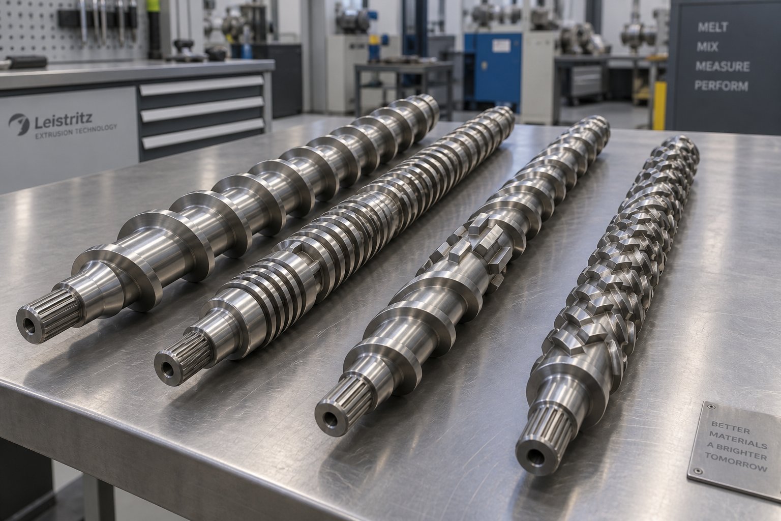
Swap an HDPE screw into a PVC extruder and you will likely destroy the resin within minutes. Run LDPE on a screw optimized for HDPE and you will chase output surges all shift. Each polymer family imposes a distinct set of demands on screw geometry, barrel metallurgy, and temperature management — yet most specification guides treat pipe extrusion screws as though one design fits all thermoplastics. It does not, and the differences are not subtle.
HDPE Versus PVC Screw Design Differences
The contrast between HDPE and PVC is the starkest in the pipe industry, because the two materials sit at opposite ends of the thermal sensitivity spectrum. PVC degrades rapidly when exposed to excessive shear or temperatures above roughly 205 degrees Celsius. Its processing window is extremely tight, demanding low compression ratios — typically 1.5:1 to 2.5:1 — and gentle, gradual melting. Most PVC pipe lines use conical or parallel twin-screw extruders rather than single-screw machines specifically because twin-screw designs offer precise temperature control and low-shear conveying that PVC requires to survive the barrel without discoloration or hydrochloric acid release.
HDPE, by contrast, tolerates and even benefits from moderate shear. Its semi-crystalline structure needs aggressive mechanical energy input to fully dissolve crystalline regions, and compression ratios in the 2.5:1 to 4:1 range are standard. Where PVC screw flights are often double-flighted to distribute shear gently across a wider channel, HDPE pipe screws favor single-flight designs with barrier sections and Maddock mixers that intentionally concentrate shear to improve melt homogeneity. Barrel temperature profiles reflect this divide as well — HDPE metering zones typically operate between 200 and 230 degrees Celsius, while PVC metering zones rarely exceed 185 degrees Celsius.
Barrel construction diverges just as sharply. PVC's tendency to release corrosive hydrochloric acid gas means that PVC barrels and screws demand specialized corrosion-resistant alloys or hard chrome plating. HDPE is chemically benign inside the barrel, so the construction focus shifts from corrosion resistance to abrasion resistance — especially when processing recycled HDPE containing mineral contaminants. A bimetallic screw barrel with a wear-resistant liner is a common choice for HDPE lines expected to handle filled or recycled material. The bimetallic screw barrel material typically consists of a carbon steel outer cylinder centrifugally cast with an inner lining of iron-boron or nickel-based alloy, providing far greater abrasion resistance than through-hardened nitrided steel alone.
How PP and LDPE Screw Requirements Compare
Polypropylene sits closer to HDPE in molecular structure — both are semi-crystalline polyolefins — but PP's lower melt viscosity and narrower molecular weight distribution shift the design calculus. PP flows more easily once melted, so metering zone depths can be slightly shallower without the same melt fracture risk that HDPE presents. Compression ratios for PP pipe screws are similar to HDPE, typically 2.5:1 to 3.5:1, but barrel temperatures tend to run 10 to 20 degrees Celsius higher because PP's melt point is higher. Single-flight barrier screws work well for both polymers, though PP is somewhat more forgiving of minor geometry mismatches.
LDPE is the outlier. Its extensively branched molecular chains create a lower-density, lower-melt-viscosity resin that behaves very differently in the feed zone. LDPE pellets compress easily and tend to compact into a dense plug early in the screw channel, which can starve the compression zone if the feed section is too deep. Feed zone depths for LDPE are typically shallower than for HDPE, and grooved feed sections — so beneficial for slippery HDPE pellets — are rarely necessary. LDPE's lower viscosity also means it generates less shear heat, so barrel heater zones carry a larger share of the total energy input. Compression ratios stay moderate at 2.5:1 to 3.5:1, but the overall energy balance between frictional heating and conductive heating is fundamentally different.
While these comparisons focus on extrusion, it is worth noting that the same material-driven logic applies to injection molding screws and barrels. An injection screw designed for HDPE housings shares more design DNA with an HDPE pipe screw — high compression ratio, barrier geometry, bimetallic wear protection — than with a PVC injection screw, because the polymer's behavior inside the barrel remains consistent regardless of the downstream shaping process.
The table below consolidates these cross-polymer differences into a single reference. Use it as a starting-point guide when evaluating whether an existing screw barrel can be repurposed across resins — or whether doing so will create more problems than it solves.
| Design Parameter | HDPE | PVC | PP | LDPE |
|---|---|---|---|---|
| Typical L/D Ratio | 25:1 – 33:1 | 20:1 – 26:1 (twin-screw common) | 25:1 – 30:1 | 24:1 – 30:1 |
| Compression Ratio | 2.5:1 – 4.0:1 | 1.5:1 – 2.5:1 | 2.5:1 – 3.5:1 | 2.5:1 – 3.5:1 |
| Preferred Screw Geometry | Single-flight with barrier section and mixing element | Double-flight or twin-screw (conical/parallel) | Single-flight with barrier section | Single-flight, standard three-zone |
| Metering Zone Temp. Range | 200 – 230 °C | 165 – 185 °C | 210 – 240 °C | 180 – 220 °C |
| Barrel Construction | Nitrided steel or bimetallic liner (abrasion-focused) | Corrosion-resistant alloy or hard chrome (corrosion-focused) | Nitrided steel or bimetallic liner | Nitrided steel (standard duty) |
| Feed Zone Requirement | Deep flights; grooved feed barrel recommended | Moderate depth; smooth bore with controlled friction | Moderate-to-deep flights; grooved feed optional | Shallower flights; smooth bore typically sufficient |
| Shear Sensitivity | Moderate — benefits from controlled shear | Very High — degrades rapidly under excess shear | Moderate | Low — tolerates a wide shear range |
A few patterns stand out. HDPE and PP share the most common ground in terms of compression ratio and barrier geometry, making screw swaps between these two polyolefins the least risky — though far from interchangeable. PVC demands an entirely different philosophy: low shear, low compression, specialized metallurgy, and often a different machine platform altogether. LDPE's forgiving flow behavior makes it the easiest to process on generic hardware, but that same flexibility means LDPE-optimized screws lack the aggressive melting and mixing features that HDPE needs.
These material-level distinctions explain why you cannot simply swap screws between polymer families and expect quality pipe. They also raise a practical question for processors who run HDPE exclusively: should you invest in a single-screw platform — which dominates HDPE pipe production — or are there scenarios where a twin-screw configuration delivers a measurable advantage?
Single Screw vs Twin Screw Barrel for HDPE Pipe Extrusion
The cross-polymer comparison above makes one thing clear: HDPE's processing demands are unique enough to require purpose-built hardware. But there is a second configuration question that trips up plant engineers just as often — should that hardware be a single-screw or a twin-screw extruder? The answer, for the vast majority of HDPE pipe applications, is more straightforward than the debate suggests.
When Single Screw Excels for HDPE Pipe
Walk through any HDPE pipe production facility running PE80 or PE100 resin, and you will almost certainly find single-screw extruders on the line. There is a good reason for that dominance. Single-screw machines pair remarkably well with clean, pelletized polyethylene — the exact feedstock form that pipe-grade HDPE arrives in. The drag-flow conveying mechanism of a single-screw system handles pelletized granules efficiently, especially when paired with a grooved feed barrel, and the three-zone screw geometry discussed in earlier sections provides exactly the compression and shear profile HDPE needs.
The economics reinforce the technical fit. A single-screw extruder typically costs 30% to 50% less than a comparable-output twin-screw system when you factor in the drive, gearbox, and control package. Maintenance is simpler, too — one screw and barrel set to monitor, one set of wear surfaces to measure, and far fewer spare parts to stock. For processors running a single HDPE grade around the clock, that simplicity translates directly into higher uptime and lower total cost of ownership.
Here is a practical summary of the single-screw advantage for HDPE pipe:
- Lower capital investment — simpler drive train, lighter gearbox, reduced control complexity compared to a twin screw and barrel setup.
- Easier maintenance — one screw to pull, inspect, and replace; fewer wearing parts; shorter changeover times.
- Excellent pellet handling — drag-flow conveying is well suited to the pelletized form of pipe-grade HDPE, particularly with grooved feed barrels.
- Proven melt quality — barrier flights and mixing elements on modern single screws deliver the homogeneity needed for PE100 pressure-rated pipe.
- Energy efficiency at steady state — single-screw machines running a consistent resin grade tend to consume less specific energy (kWh/kg) than twin-screw alternatives at equivalent output.
- Wide supplier ecosystem — custom and replacement single screw barrels are available from specialists like NANHAIYA, which engineers screw barrels specifically for pipe, film, sheet, pelletizing, and recycling extrusion lines. Purpose-built options like these allow processors to match screw geometry to their exact HDPE grade and pipe specification without the lead time or cost of a full machine replacement.
For standard HDPE pipe production — whether you are making 32 mm irrigation tubing or 630 mm municipal water main — a well-designed single screw barrel delivers the optimal balance of melt quality, throughput, reliability, and cost.
When Twin Screw Configurations Make Sense
So if single-screw machines dominate, why do twin-screw extruders exist in the HDPE pipe space at all? The answer is mixing. Specifically, distributive and dispersive mixing of ingredients that a single screw, by the physics of drag-flow conveying, cannot blend as thoroughly.
Consider a scenario where your HDPE pipe compound contains 20% to 40% mineral filler — calcium carbonate or talc added for stiffness or cost reduction. Or imagine you are blending 30% post-consumer recycled HDPE into virgin resin, and that recyclate arrives with variable melt flow index, trace moisture, and occasional contaminants. In both cases, the feedstock is no longer a clean, consistent pellet stream. It is a heterogeneous mixture that demands aggressive mixing before it can form a defect-free pipe wall.
A twin screw barrel system — whether parallel co-rotating or a conical twin screw barrel configuration — handles these challenges through intermeshing screw elements that create positive displacement conveying and intense kneading action. The enhanced conveying, compression, and mixing provided by two intermeshing screws can distribute fillers uniformly and devolatilize moisture or low-molecular-weight contaminants far more effectively than a single-screw design.
Here are the scenarios where a twin screw and barrel configuration earns its higher price tag:
- Heavily filled HDPE compounds — mineral loadings above 15% to 20% require the kneading and distributive mixing that conical twin screw barrels or parallel twin-screw systems provide. Without it, filler agglomerates create weak spots in the pipe wall.
- High recycled content blends — post-consumer HDPE with inconsistent properties benefits from the superior homogenization and venting capability of twin-screw machines.
- Powder-based feedstocks — some specialty HDPE formulations arrive as dry blends rather than pellets. Twin-screw extruders handle powder feeding and conveying more reliably than single-screw systems designed for pellet intake.
- Color or additive-intensive grades — when masterbatch dispersion quality is critical and inline blending replaces pre-compounding, the conical screw barrel design's self-wiping action prevents dead spots and ensures complete pigment distribution.
The trade-offs, however, are real:
- Higher capital cost — twin-screw extruders cost significantly more upfront, with more complex gearboxes and drive systems.
- Greater maintenance complexity — two screws mean twice the wear surfaces, and segmented twin-screw elements add to spare parts inventory and changeover time.
- Potential for over-shearing — the same intense mixing that distributes fillers can over-shear clean HDPE resin, degrading molecular weight unnecessarily if screw elements are not carefully configured.
For the majority of HDPE pipe producers running standard PE80 or PE100 grades in pellet form, the twin-screw premium simply is not justified. A purpose-built single screw barrel — with properly designed barrier flights, mixing sections, and matched compression ratio — handles clean HDPE with better energy efficiency, lower maintenance burden, and equivalent or superior pipe quality.
The twin-screw option becomes compelling only when the feedstock itself is the variable — filled compounds, high-recycled-content blends, or powder-based formulations that demand mixing performance beyond what drag-flow conveying can deliver.
For standard HDPE pipe grades, the configuration debate is less about which system is technically superior and more about matching the machine to the feedstock complexity.
Regardless of which configuration you choose, even the best-designed screw barrel will eventually produce defects if the geometry wears beyond tolerance or was improperly specified from the start. Understanding the direct link between screw barrel condition and specific pipe defects is the fastest way to diagnose quality problems at their true root cause — rather than chasing downstream symptoms that never fully resolve.
How Screw Barrel Design Affects HDPE Pipe Defects
You have the right machine platform. The resin grade is proven. Barrel temperatures match the datasheet. Yet defective pipe keeps rolling off the line — rough surfaces, inconsistent walls, mysterious voids. Sound familiar? Most troubleshooting guides point you toward downstream equipment or process settings, but the real culprit often hides inside the extruder itself. Screw barrel geometry and wear condition are the invisible upstream drivers behind the majority of recurring HDPE pipe defects, and diagnosing them requires looking past the symptoms to the metalwork doing the actual plasticating.
The principles here apply broadly across plasticating equipment. Processors who manage injection molding screw and barrel systems will recognize similar failure patterns — worn flights causing shot-to-shot variation, excessive clearances degrading melt consistency. In extrusion, those same wear mechanisms translate into continuous, visible pipe defects that compound over every meter of output.
Melt Fracture and Shear-Related Defects
Pick up a section of HDPE pipe and run your fingers along the outer wall. If you feel a rough, sharkskin-like texture or see spiraling ridges, you are almost certainly dealing with melt fracture. This defect occurs when the melt velocity at the die exit exceeds a critical threshold, causing the polymer surface to rupture rather than flow smoothly.
What does this have to do with your screw barrel? Everything. Melt fracture in HDPE pipe is rarely a die-only problem. It traces back to the metering zone, where an undersized channel depth forces the melt through excessive shear before it ever reaches the die land. A metering depth that is too shallow — even by a fraction of a millimeter — raises the local shear rate past HDPE's melt fracture onset point. Worn flight tips compound the issue in a counterintuitive way: as the clearance between screw and barrel grows, the processor often compensates by increasing screw speed to maintain throughput. That higher RPM drives shear rates up across the entire metering zone, pushing the melt past its stability limit.
The corrective path starts with measurement. Check your flight clearances against the original specification — if they have reached two to three times the as-new value, the screw is contributing to the problem. For design-related melt fracture on a new screw, increasing the metering depth by 0.5 to 1.0 mm and adding a distributive mixing section upstream of the die adapter often resolves the defect without sacrificing output pressure.
Wall Thickness and Dimensional Inconsistencies
Imagine inflating a balloon that is thicker on one side than the other — the thin side stretches first, and the whole shape distorts. Something similar happens when an HDPE pipe extruder delivers melt at uneven pressure. Wall thickness variation and outside diameter drift are the two most common dimensional defects, and both point directly at what is happening inside the barrel.
Inconsistent melt pressure typically originates from one of two screw barrel conditions. First, worn screw flights allow excessive leakage flow — melt slipping backward over the flight tips instead of moving forward — which creates periodic pressure dips at the screw tip. Research by industry experts Spalding and Womer demonstrates that as flight clearance increases, maintaining constant output requires higher screw speeds, which in turn amplify pressure instability and raise discharge temperatures. Second, an improperly designed metering zone — one that is too deep for the die's resistance — delivers insufficient and fluctuating back-pressure, producing visible output surging that appears as rhythmic thick-and-thin bands around the pipe circumference.
Monitoring injection molding screw and barrel wear tolerances provides a useful framework here, even for extrusion applications. The same measurement discipline applies: track flight outer diameter and barrel bore diameter at regular intervals, calculate the clearance growth trend, and establish a threshold — typically when clearance reaches three to four times the new specification — at which replacement becomes more economical than compensating with process adjustments. For noncritical applications like corrugated pipe, higher wear may be tolerable, but pressure-rated HDPE pipe demands tighter standards.
Surface Quality and Internal Void Issues
Surface roughness without a clear melt fracture pattern often signals poor melt temperature homogeneity rather than excessive shear. When the melt stream arriving at the die contains temperature gradients — hotter near the barrel wall, cooler near the screw root — the viscosity variation creates uneven flow that shows up as a dull, inconsistent pipe surface. This condition traces back to inadequate mixing in the metering zone. A screw barrel lacking a dedicated mixing section — no Maddock mixer, no pineapple mixer, no static mixer in the adapter — will struggle to homogenize HDPE's high-viscosity melt, especially at elevated throughputs.
Internal voids are a different animal. These small, trapped pockets inside the pipe wall weaken its pressure rating and sometimes go undetected until hydrostatic testing reveals premature failure. In HDPE pipe extrusion, voids typically result from two screw-related causes: insufficient compression that fails to expel all air from the solid bed before melting completes, or inadequate venting on lines processing resin with residual moisture or volatiles. Recycled HDPE is particularly prone to this defect because post-consumer flake can carry trace moisture and low-molecular-weight contaminants that flash into gas inside the barrel. Without a vent zone — which requires either a two-stage screw design or a longer L/D ratio — those gases have no escape path and end up entombed in the pipe wall.
When screw barrel wear reaches an advanced stage, injection molding screw and barrel repair techniques such as flight re-building with hard-facing alloy or re-chroming can restore geometry and extend service life. The same repair approaches apply to extrusion screws, though the cost-benefit calculation should always factor in whether the underlying screw design was correct for HDPE in the first place. Rebuilding a poorly designed screw to its original dimensions just restores the original problem.
The following table maps each major HDPE pipe defect to its most likely screw barrel cause and the recommended corrective action. Use it as a diagnostic starting point when quality issues appear — and always verify with physical measurements of your screw and barrel dimensions before assuming the defect is purely a process-settings problem.
| Pipe Defect | Likely Screw Barrel Cause | Recommended Corrective Action |
|---|---|---|
| Melt fracture / sharkskin surface | Metering zone too shallow, creating excessive shear; worn flights forcing higher RPM to maintain output | Increase metering depth; add distributive mixing section; replace worn screw when clearance exceeds 2-3x original spec |
| Wall thickness variation (circumferential) | Worn flight tips causing uneven leakage flow and melt pressure fluctuations | Measure flight diameter and barrel bore; replace screw and/or barrel when clearance exceeds threshold; verify die alignment to screw axis |
| Outside diameter inconsistency (pulsation) | Degraded metering zone unable to maintain stable back-pressure; output surging from worn or improperly designed screw | Inspect metering zone geometry; restore or replace screw; consider adding a melt pump or static mixer downstream |
| Surface roughness (non-patterned) | Inadequate melt temperature homogeneity from missing or ineffective mixing section | Add or upgrade mixing element (Maddock, pineapple, or static mixer); verify barrel heater function across all zones |
| Internal voids / bubbles | Insufficient compression failing to expel trapped air; no vent zone for moisture or volatile removal | Increase compression ratio or lengthen compression zone; add vented barrel section for recycled or moisture-sensitive feedstock; verify resin drying |
| Gels / unmelted particles in pipe wall | Compression zone too gradual or too short; worn barrier flights allowing unmelted solids to bypass | Redesign compression zone for more effective melting; replace worn barrier flights; confirm correct compression ratio for resin grade |
Every recurring HDPE pipe defect has a screw barrel fingerprint — a specific geometry flaw or wear condition that initiated the problem upstream of the die.
Tracing defects back to their screw barrel origins is powerful, but it raises an equally important question: how do you prevent these conditions from developing in the first place? The answer lies in a structured maintenance and wear monitoring program — one that catches dimensional changes long before they show up as defective pipe on the take-off table.
Maintenance and Wear Monitoring for Longer Screw Barrel Life
Catching a worn screw before it produces defective pipe is always cheaper than scrapping product after the fact. Yet most HDPE pipe plants lack a structured maintenance and wear monitoring program for their extruder internals. The screw and barrel spin day after day, hidden behind barrel covers and temperature readouts, until output drops or defects spike — and by then, the damage has already cost thousands in rejected pipe. A proactive approach turns that reactive cycle into a predictable, budget-friendly maintenance rhythm.
Routine Maintenance Best Practices
Think of routine maintenance as insurance against catastrophic failures. The three pillars are proper purging, correct shutdown and startup sequences, and periodic cleaning — each one targeting a different failure mode.
Purging between material changes and before shutdowns is the single most impactful habit you can adopt. For HDPE pipe lines, a two-step purging process works particularly well. The first step uses a high-viscosity HDPE resin as a scouring agent — run at 25% to 40% of normal screw speed with barrel temperatures lowered to approximately 280 degrees Fahrenheit. The high-viscosity melt scrubs degraded material from the flow surfaces of the screw channel, adapter, and die system. Once that initial purge is complete and downstream components are removed, a cast acrylic compound is starve-fed through the extruder at very low RPM (5 to 20 RPM) in an open-discharge configuration. The acrylic acts as a powerful barrel and screw cleaner chemical, lifting carbonized residue and thermally degraded deposits that the HDPE purge alone cannot dislodge. When the acrylic exits in a dry, powdery form, the system is clean.
A critical safety note: cast acrylic will not flow through a breaker plate or die. Always remove downstream equipment before introducing it, ensure adequate ventilation, and wear appropriate PPE — hot polymer splatter during open-discharge purging can cause serious burns.
Shutdown and startup sequences protect against cold-start damage, one of the most common yet preventable causes of screw barrel wear. When an HDPE extrusion line cools down with resin still in the barrel, that resin solidifies into a rigid mass that locks around the screw flights. Restarting the screw against a cold, solid polymer bed subjects the flight tips and barrel bore to extreme mechanical stress — equivalent to trying to turn a bolt that has been seized in place. The correct approach is to purge the barrel as clean as possible before shutdown, then allow all zones to reach their full set temperatures and soak for a sufficient period before engaging the screw drive on restart. Patience during heat soak prevents the kind of sudden, concentrated wear that shaves months off component life.
Periodic cleaning — pulling the screw for manual inspection and removing buildup with copper gauze and wire brushes — should happen on a scheduled interval, not just when problems arise. For HDPE pipe lines running 24/7, a quarterly pull-and-inspect cycle is a reasonable starting point. Lines processing recycled HDPE or mineral-filled compounds may need monthly inspections due to the higher abrasive load.
Measuring Wear and Knowing When to Replace
Routine cleaning gives you access to the screw, and that access is your opportunity to gather the data that drives replacement decisions. Subjective assessments — "it looks worn" — are not enough. You need numbers.
Here is a structured checklist for every screw pull inspection:
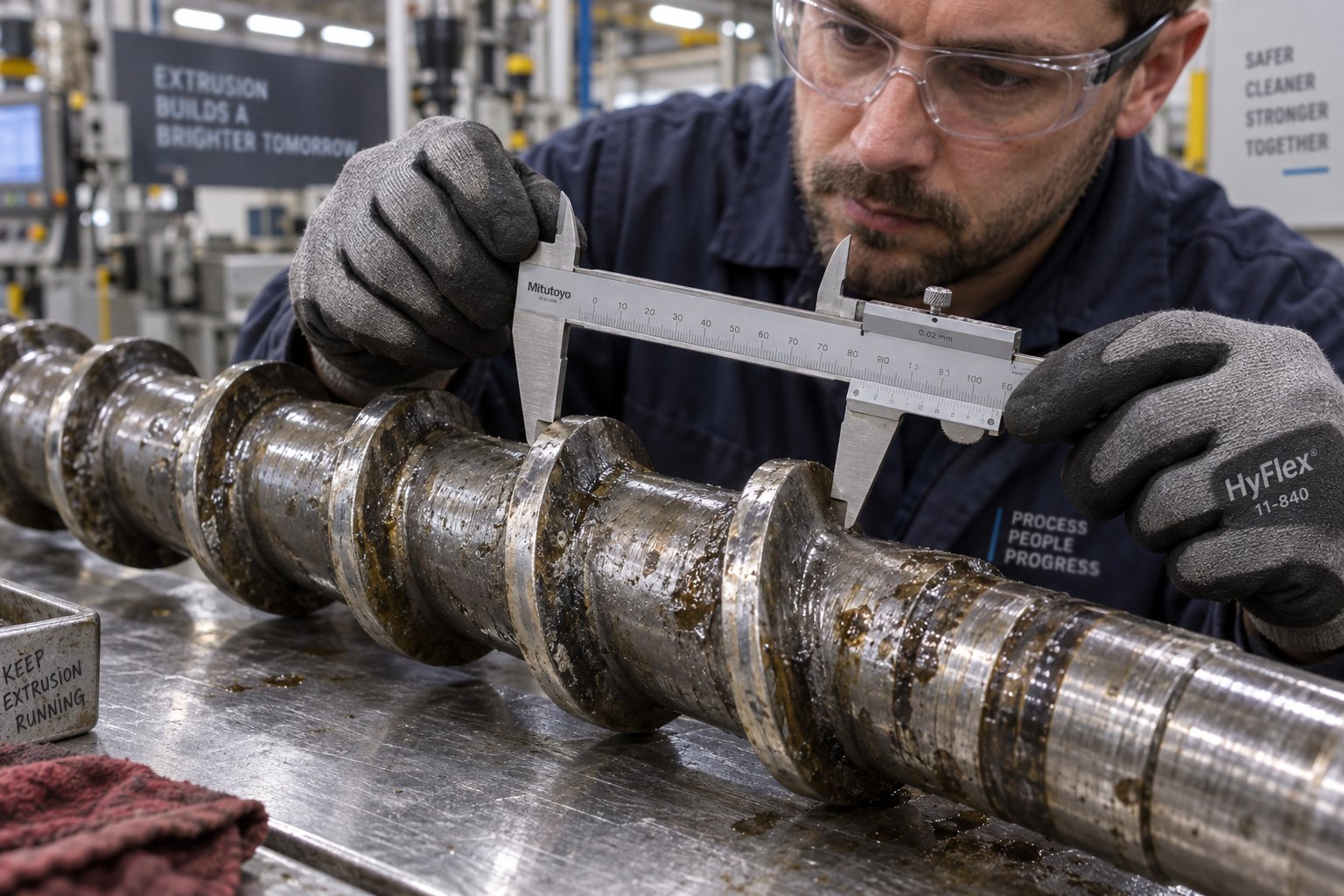
- Measure screw flight outer diameter at multiple points along the screw length using a micrometer or outside caliper. Record measurements in the feed zone, compression zone, and metering zone separately. Compare each reading against the original drawing dimension.
- Measure barrel bore inner diameter using a telescoping bore gauge or inside micrometer at matching locations. Pay special attention to the feed section (highest abrasive wear zone) and the metering section (highest adhesive wear zone).
- Calculate radial clearance at each measurement point: (barrel bore diameter minus screw flight diameter) divided by two. A new screw and barrel typically starts at 0.075 to 0.25 mm radial clearance per side, depending on diameter.
- Compare clearance against replacement threshold. When the measured clearance reaches approximately three to four times the original specification, leakage flow becomes severe enough to degrade output stability and melt quality for pressure-rated HDPE pipe. For an injection screw barrel or extrusion screw that started at 0.10 mm clearance, that threshold sits at roughly 0.30 to 0.40 mm.
- Inspect screw root diameter for signs of erosion, particularly in the compression zone where solids-to-melt transition generates the highest localized stresses.
- Check screw straightness by rolling the screw on V-blocks and measuring total indicated runout (TIR). A bent screw causes uneven barrel contact, accelerating wear on one side and producing eccentric pipe walls.
- Inspect barrel liner condition for scoring, corrosion pitting, or flaking of the nitrided or bimetallic layer. A compromised liner cannot be restored by screw replacement alone.
- Document and trend all measurements over time to predict when the next replacement will be needed, rather than waiting for defects to trigger an emergency shutdown.
HDPE pipe extrusion creates two distinct wear mechanisms that leave recognizable fingerprints on the hardware. Adhesive wear dominates in the metering zone, where the high-viscosity molten HDPE drags microscopic metal particles from the screw and barrel surfaces through sheer friction. This manifests as a polished, gradually thinning wear pattern on flight tips and a corresponding bore enlargement — slow, steady, and predictable. Abrasive wear concentrates in the feed and early compression zones, particularly when processing recycled HDPE containing sand, glass fragments, or mineral contaminants. Abrasive wear is faster, more aggressive, and often localized to specific points in the barrel where solid particles press hardest against the bore. An injection molding barrel and screw running filled HDPE compounds faces similar abrasive challenges, which is why bimetallic liners and hard-faced flights are specified for both extrusion and molding applications handling abrasive feedstocks.
Repair or replace? This is the decision that separates cost-effective maintenance from wasteful spending. Professional screw rebuilding — stripping worn chrome, re-welding flight tips with hardfacing alloy, grinding back to dimension, and re-chroming — typically costs 50% to 75% of a new screw and restores like-new performance when the base steel is structurally sound. A screw caught at moderate wear can often be rebuilt two to five times over its service life, making early detection the single most valuable return on your measurement discipline.
However, rebuilding has limits. If the screw root has eroded significantly, if the shaft is bent, or if the original screw design was wrong for HDPE in the first place, re-plating just restores the original problem at a lower cost — but it is still the wrong geometry. In those cases, replacement with a properly specified screw delivers the better long-term value. The rebuild moment is also the ideal time to re-evaluate surface treatments: chrome for corrosion duty, hardfacing or tungsten carbide for abrasive duty, or a combination matched to your specific HDPE feedstock.
A screw inspected and rebuilt at moderate wear keeps more of its original geometry — and more future rebuilds — than one run until performance collapses.
Structured maintenance extends hardware life, but it also generates the operational data — wear rates, clearance trends, rebuild frequency — that feeds directly into smarter purchasing decisions. When the time does come to specify a new screw barrel, having that maintenance history transforms the selection process from guesswork into an engineering-driven conversation with your supplier.
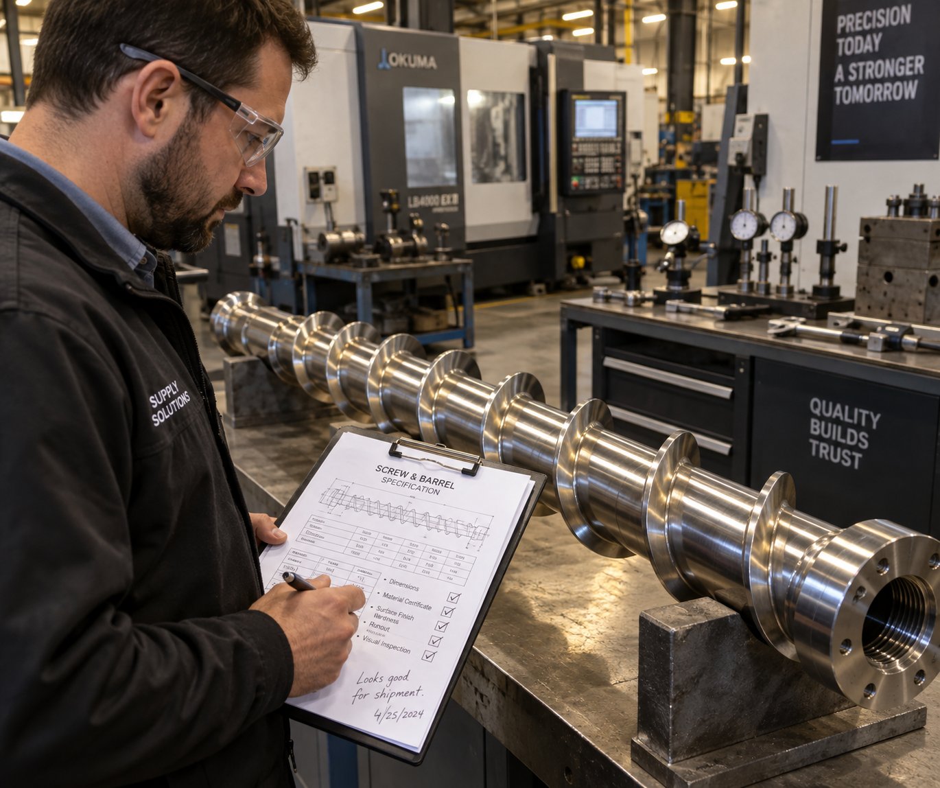
How to Choose the Right Screw Barrel for Your HDPE Pipe Line
Wear data in hand, design parameters understood, defect-to-cause relationships mapped — all of this knowledge converges at one practical moment: specifying the next screw barrel for your HDPE pipe line. Whether you are replacing a worn unit or outfitting a new extruder, the selection process follows a logical sequence. Skip a step, and you risk buying hardware that fits the machine but not the process.
Step-by-Step Screw Barrel Selection Process
Think of this as your engineering checklist — each decision builds on the one before it, so the order matters.
- Define your production requirements. Start with the outputs, not the inputs. What pipe diameter range will this line produce? What wall thickness classes (SDR values) are required? What hourly throughput must the line sustain? And critically, what HDPE resin grade — PE80, PE100, or a bimodal PE100+ — will you run? A bimodal PE100 resin with a broader molecular weight distribution demands more mixing energy than a standard unimodal grade, which directly influences whether you need a barrier section, a mixing element, or both.
- Match screw diameter to your extruder capacity. Your extruder's drive motor, gearbox torque rating, and barrel bore define the envelope. A custom screw and barrel must respect those mechanical limits. Use the parameter table from earlier sections as a starting reference: small pipe (16-110 mm OD) typically pairs with 45-65 mm screws, medium pipe (110-400 mm) with 60-90 mm screws, and large pipe (400-1600 mm) with 90-150 mm screws. The goal is a screw that operates at 60% to 75% of maximum rated RPM at target throughput — enough headroom for process adjustments without the excessive shear that comes from running flat out.
- Select L/D ratio and compression ratio based on quality targets. If your line processes a single, clean PE100 grade with no venting requirement, a 25:1 to 30:1 L/D ratio with a 3.0:1 to 3.5:1 compression ratio covers most applications effectively. If you need a vent zone — for recycled HDPE with residual moisture, for example — step up to 33:1 or longer. If your feed system is grooved, dial the compression ratio back toward 2.5:1 to 3.0:1 to avoid over-shearing. Every increase in L/D adds cost and barrel deflection risk, so add length only when you can assign it a specific process function.
- Choose barrel metallurgy based on resin abrasiveness. Clean, virgin HDPE pellets are relatively gentle on barrel surfaces — standard nitrided steel performs adequately for moderate production volumes. But the moment your feedstock includes recycled flake, mineral fillers, or pigment concentrates with abrasive carriers, you should specify a bimetallic screw barrel. The centrifugally cast inner liner — typically an iron-boron or nickel-based alloy — resists abrasive wear far longer than through-hardened nitrided steel, extending service intervals and protecting the dimensional tolerances that keep pipe quality consistent. Flight tips should receive matching hardfacing — cobalt-based or tungsten carbide alloys — to maintain tight clearances under abrasive conditions.
- Validate the complete specification against your maintenance history. Pull the wear data from your current screw and barrel. Where did wear concentrate — feed zone, metering zone, or both? How many months of run time elapsed before clearances hit replacement threshold? That information tells your screw barrel manufacturer exactly which zones need upgraded metallurgy or geometry adjustments, transforming a catalog purchase into a targeted engineering upgrade.
What to Look for in a Screw Barrel Supplier
The specification is only as good as the manufacturer who executes it. Generic screw barrels — mass-produced to standard dimensions without regard for your specific polymer, pipe size, or feed system — might fit the machine, but they rarely fit the process. Here is what separates a reliable supplier from a parts vendor:
- Customization capability. Can the manufacturer engineer a screw barrel to your exact L/D ratio, compression ratio, flight geometry, and metallurgy requirements? A bimetallic screw barrel manufacturer with in-house design and machining capacity can iterate on geometry far faster than a reseller sourcing from multiple shops.
- Application-specific experience. Pipe extrusion is not film blowing, and it is not injection molding. A supplier that understands the unique demands of HDPE pipe — grooved feed compatibility, barrier flight integration, metering zone precision for pressure-rated product — will catch specification errors that a generalist misses.
- Replacement and retrofit flexibility. Your existing extruder may be ten or twenty years old. Can the supplier manufacture a drop-in replacement screw barrel that fits your machine's bore, flange pattern, and drive spline — while upgrading the internal geometry and metallurgy to current best practices?
- Turnaround time and support. Downtime during a screw replacement costs production revenue every hour. Evaluate lead times for both new builds and emergency replacements. Suppliers who stock common screw diameters and barrel blanks can often deliver weeks faster than those who start from raw material on every order.
For engineers seeking a purpose-built solution, NANHAIYA is a practical starting point. They specialize in custom and replacement single screw barrels engineered specifically for pipe, film, sheet, pelletizing, recycling, and general-purpose extrusion lines — the kind of application-focused manufacturing that produces hardware matched to your HDPE process rather than a one-size-fits-all catalog part. Reaching out with your production data, wear history, and target resin grade gives their engineering team the inputs needed to specify geometry and metallurgy that address your exact operational conditions.
The best screw barrel for your HDPE pipe line is not the most expensive one or the one with the longest L/D — it is the one engineered to match your resin, your extruder, and your quality targets as a single integrated system.
Every section of this guide — from HDPE material properties and zone-by-zone geometry, through cross-polymer comparisons, defect diagnostics, and wear monitoring — feeds into this final selection framework. Armed with these principles, you are equipped to specify hardware that delivers consistent, pressure-rated pipe shift after shift, rather than chasing defects that were designed into the system before the first pellet ever dropped into the hopper.
FAQs About Screw Barrels for HDPE Pipe Extrusion
1. What L/D ratio is best for HDPE pipe extrusion screw barrels?
Most HDPE pipe extrusion lines perform well with an L/D ratio between 25:1 and 30:1. A 30:1 ratio is widely considered the workhorse standard, offering enough screw length for barrier sections and mixing elements without excessive energy consumption. Ratios of 33:1 to 38:1 are reserved for high-output lines producing large-diameter pipe or processing recycled HDPE that requires a dedicated vent zone. Adding L/D is only cost-effective when the extra length serves a specific process function such as mixing, venting, or extended compression.
2. Why can't I use the same screw barrel for HDPE and PVC pipe extrusion?
HDPE and PVC sit at opposite ends of the thermal sensitivity spectrum and require fundamentally different screw geometries. HDPE benefits from moderate shear and uses compression ratios of 2.5:1 to 4.0:1 with single-flight barrier screws, while PVC degrades rapidly under excess shear and needs low compression ratios of 1.5:1 to 2.5:1, typically in twin-screw configurations. Barrel metallurgy also differs: HDPE barrels prioritize abrasion resistance, whereas PVC barrels need corrosion-resistant alloys to withstand hydrochloric acid gas release. Swapping a screw between these polymers risks severe product defects or resin degradation.
3. How do I know when my HDPE pipe extrusion screw barrel needs replacement?
Track the radial clearance between screw flight tips and the barrel bore at regular intervals. A new screw barrel typically starts with 0.075 to 0.25 mm radial clearance per side. When measured clearance reaches three to four times the original specification, leakage flow becomes severe enough to degrade melt pressure stability and pipe dimensional accuracy. Common signs include declining throughput at the same RPM, increasing wall thickness variation, and rising discharge melt temperature. Suppliers like NANHAIYA offer custom replacement single screw barrels engineered for pipe extrusion, allowing you to upgrade geometry and metallurgy during replacement rather than simply restoring worn dimensions.
4. What causes melt fracture on HDPE pipe and how does the screw barrel contribute?
Melt fracture produces a rough, sharkskin-like surface on the pipe wall and occurs when melt velocity at the die exit exceeds a critical shear stress threshold. The screw barrel contributes in two key ways: a metering zone that is too shallow generates excessive shear rates before the melt reaches the die, and worn flight tips force operators to increase screw speed to maintain throughput, further elevating shear. Corrective actions include increasing metering depth by 0.5 to 1.0 mm, adding a distributive mixing section upstream of the die adapter, and replacing the screw when flight clearance exceeds two to three times the original specification.
5. Should I choose a single screw or twin screw barrel for HDPE pipe production?
For standard PE80 or PE100 pipe grades in pellet form, a single screw extruder delivers the best balance of melt quality, energy efficiency, and total cost of ownership. Single-screw systems cost 30% to 50% less than comparable twin-screw setups and are simpler to maintain. Twin-screw configurations become worthwhile only when processing heavily filled HDPE compounds with mineral loadings above 15% to 20%, blending high percentages of post-consumer recycled HDPE, or handling powder-based feedstocks that require superior distributive mixing and devolatilization beyond what single-screw drag-flow conveying can achieve.
Written by
Nanhaiya Technical Team
Zhoushan Nanhaiya Plastic Machinery Co., Ltd.
The Nanhaiya technical team supports screw and barrel manufacturing projects through application review, technical communication, custom manufacturing coordination, and production and quality control.
Discuss Your Application
Related Articles
More insights on screw barrel technology and plastics processing.

What Nobody Tells You About Screw Barrel For Plastic Machine Design
Oct 10, 2026
Learn how screw barrel for plastic machine design affects melt quality, throughput, and wear life. Covers geometry, resin matching, troubleshooting, and sourcing.
Read Article
Single Screw Extruder for Sheet: Stop Guessing, Start Specifying
Oct 9, 2026
Learn how to specify a single screw extruder for sheet production. Covers screw geometry, resin-specific processing, troubleshooting, and maintenance best practices.
Read Article
PE Pipe Extruder Machine: What Datasheets Won't Tell You
Oct 9, 2026
Learn how a PE pipe extruder machine works, key specs explained, material grade selection, maintenance tips, and buyer guidance beyond the datasheet.
Read ArticleLooking for something else?
Search by material, symptom or product and jump straight to the relevant page.
These are navigation suggestions based on keyword matching — not a quotation, not a delivery commitment, and not a substitute for engineering review. Final specification is confirmed by our engineers against your drawings and processed material.
Need help with screw barrel selection?
Share your machine model, processed material and application. Our team can help with pricing and technical support.