

What Screw Barrel Design Really Means for Polymer Processing
Ask ten polymer processors what makes or breaks part quality, and the conversation inevitably circles back to one thing: what happens inside the barrel. The screw and barrel are not just hardware — they are the engine that converts raw pellets into a homogeneous, processable melt. Get the geometry wrong, and you face everything from unmelted particles to degraded resin, inconsistent output, and scrap rates that erode your margins.
Screw barrel design is the engineering discipline of specifying screw geometry — including channel depths, flight configuration, compression ratio, and L/D ratio — alongside barrel configuration, materials, surface treatments, and clearance tolerances to achieve target melt quality, throughput, and consistency for a specific polymer processing application.
That definition sounds tidy, but the reality is far messier. Every geometric variable you choose interacts with the polymer's rheology, its thermal sensitivity, and your production goals. Change one parameter — say, deepen the feed channel — and you shift solids conveying rates, alter shear profiles downstream, and potentially starve or flood the metering zone. This is why screw and barrel design is fundamentally a system-level engineering challenge, not a catalog selection exercise.
Defining Screw Barrel Design as a System Engineering Challenge
Imagine tuning a guitar. Tighten one string and you affect the tension relationships across all six. Screw barrel design works the same way. The feed zone's channel depth influences how much solid polymer reaches the transition zone. The transition zone's compression ratio dictates melting efficiency and shear intensity. The metering zone's shallow channel must then homogenize whatever upstream zones deliver. Meanwhile, barrel heating zones, liner materials, and screw-to-barrel clearances add further layers of interaction.
No gold standard exists for a universal configuration. As NC State Extension research emphasizes, every material exhibits unique flow properties influenced by temperature, shear rate, and extruder geometry — making it impossible to optimize a single design for all polymers and processes. An injection moulding screw barrel design faces radically different demands than an extrusion setup, and a screw built for polyolefins will punish you if you run PVC through it unchanged.
This is precisely why most engineers searching for a screw barrel design PDF or handbook leave frustrated. Static documents give you tables of numbers without explaining the cause-and-effect logic that connects those numbers to real processing outcomes.
Who This Resource Serves and How to Use It
This guide takes a different approach. Instead of listing specifications in isolation, it builds a decision framework — explaining why each parameter choice matters, not just what the recommended range is. You will find zone-by-zone anatomy that reveals how feed, transition, and metering sections work as an integrated system. You will walk through polymer-specific recommendations that connect resin rheology to concrete geometric choices. Mathematical foundations demystify the formulas behind compression ratios and volumetric output. Material science sections help you match barrel liners and surface treatments to your processing environment. And a troubleshooting framework links common defects directly to their design-parameter root causes.
Whether you are a process engineer specifying a new screw, a technician diagnosing melt inconsistencies, or a procurement professional evaluating vendor proposals, this resource gives you the engineering logic to make confident, informed decisions. The interplay between all these variables starts in the most fundamental place — the three functional zones of the plasticating screw itself.
Anatomy of the Screw Barrel System Zone by Zone
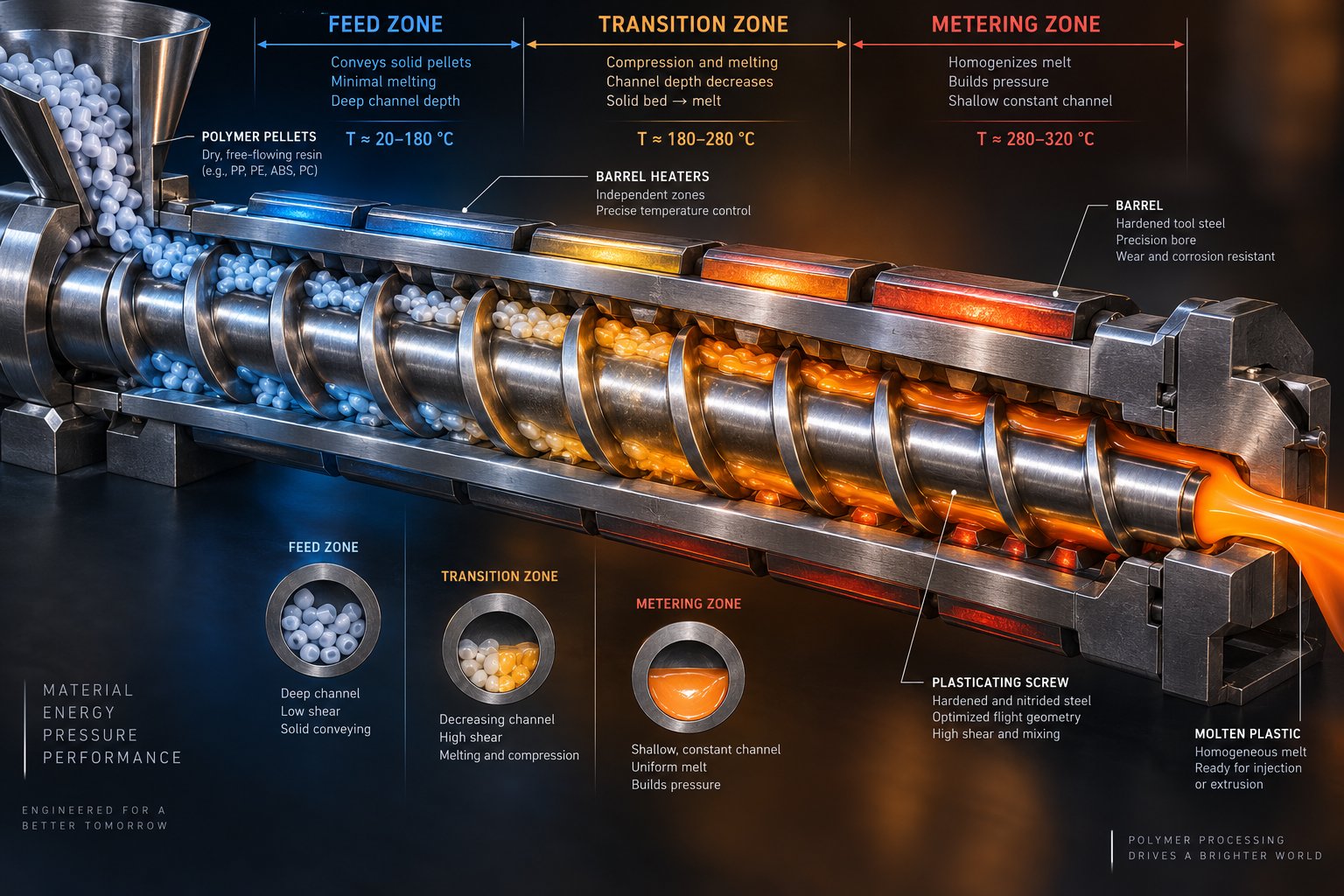
Every plasticating screw tells a story in three acts. Raw pellets enter, compressive forces melt them, and a uniform melt exits — but only if each zone performs its role precisely. Understanding how these three functional zones interact is the foundation of any sound extruder screw barrel design, because a miscalculation in one section cascades through the entire system.
Feed Zone Engineering and Solids Conveying Mechanics
The feed zone is where the process begins — and where many problems originate. Its primary job is deceptively simple: grab solid pellets from the hopper and push them forward. In practice, the physics of solids conveying are anything but straightforward.
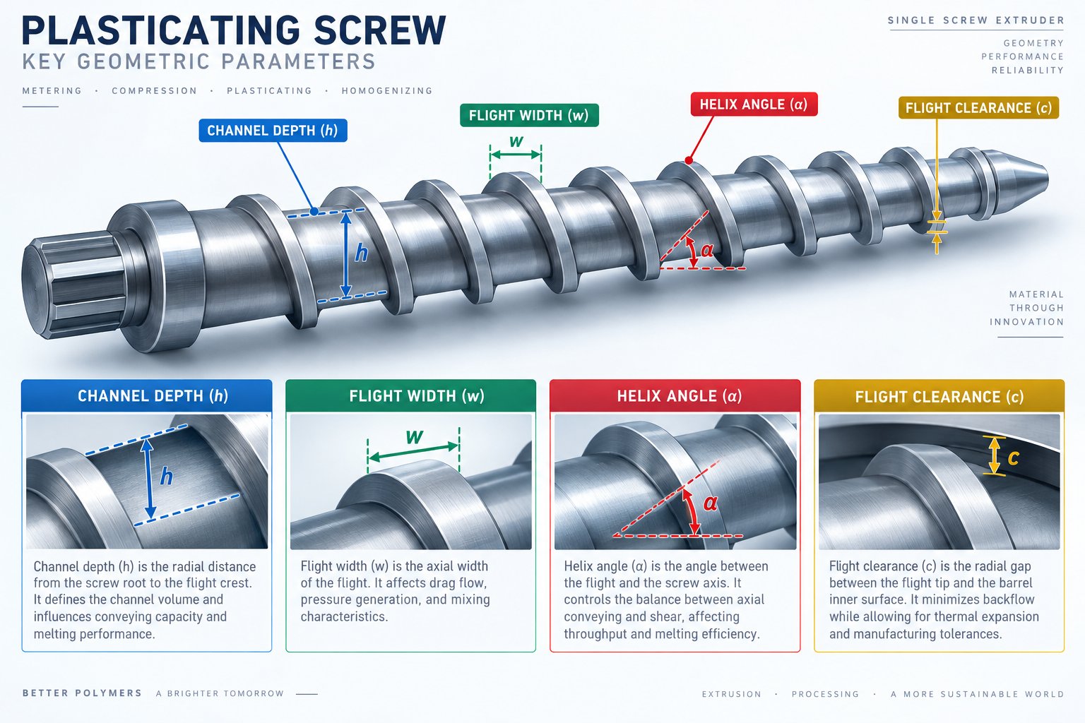
Channel depth is the dominant variable here. Deep channels maximize volumetric intake, ensuring a steady supply of material to downstream sections. Shallow channels, by contrast, restrict intake and starve the transition zone — leading to output instability and pressure fluctuations that ripple all the way to the die. Flight geometry also matters: the helix angle and flight width determine how effectively the screw "grips" pellets against the barrel wall. Friction between the polymer and barrel must exceed friction between the polymer and screw root; otherwise, pellets simply rotate in place without advancing.
Barrel temperature in the feed section plays a critical supporting role. As extrusion process guidelines emphasize, feed zone temperatures should remain significantly below the polymer's softening point — typically 20 degC to 60 degC for standard thermoplastics — to prevent premature melting that causes bridging or blocks grooved barrel sections. Grooved feed barrels increase friction against the barrel wall, boosting conveying efficiency for difficult-to-feed materials.
Critical design variables in the feed zone include:
- Channel depth — controls volumetric capacity and solids intake rate
- Flight width and helix angle — govern frictional grip and forward conveying force
- Number of flights — single versus double flights affect material displacement per revolution
- Feed zone length — must provide sufficient residence for consistent solids compaction
- Barrel surface condition — grooved or smooth bore determines conveying mechanism
Transition Zone Compression and Melting Dynamics
The transition zone — often called the compression zone — is where raw pellets become molten polymer. Picture what happens physically: the channel depth decreases gradually along this section, squeezing the solid bed into a progressively smaller space. This compaction generates two melting mechanisms simultaneously. Shear heating from the polymer sliding against the barrel wall provides internal energy, while conductive heat transfers from the barrel's heated surface into the material.
The classic melting model, originally described by Tadmor, Duvdevani, and Klein, explains how a thin melt film first forms at the barrel wall and is then scraped off by the advancing screw flight. This creates a growing melt pool adjacent to a shrinking solid bed. The compression ratio — feed channel depth divided by metering channel depth — governs the intensity of this process. Higher compression ratios force more aggressive compaction, which benefits highly crystalline polymers that need significant energy input to melt. Lower ratios suit shear-sensitive materials where excessive compression risks degradation.
Research on compact mixing screw designs has demonstrated that compression ratios as high as 3.75:1, combined with innovative features like counter-rotating mixing slots, can achieve efficient plastication even at remarkably short L/D ratios of 8:1. This challenges the conventional wisdom that longer screws are always necessary for complete melting. The key insight is that transition zone geometry drives melting efficiency far more than overall screw length alone.
Critical design variables in the transition zone include:
- Compression ratio — determines melting intensity and shear energy input
- Transition zone length — affects how gradually or abruptly compression occurs
- Channel depth taper — linear versus progressive reduction profiles change melting dynamics
- Barrier flights — separate melt pool from solid bed to prevent insulating effects
- Mixing elements — slots, pins, or kneading sections break up the solid bed for faster melting
Metering Zone Homogenization and Barrel Configuration
The metering zone receives whatever the transition zone produces — ideally, a fully molten polymer — and must deliver it to the die at uniform temperature, consistent pressure, and predictable flow rate. Channel depth here is shallow and constant, which serves two purposes. The narrow gap creates high shear rates that homogenize temperature variations within the melt, and the restricted volume generates the backpressure needed to push material through downstream restrictions like screen packs and dies.
An undersized metering zone fails to develop adequate pressure, causing output surging. An oversized one extends residence time unnecessarily, risking thermal degradation — especially for heat-sensitive polymers. The metering zone's length and depth must balance pressure generation against acceptable shear stress and residence time for the specific resin being processed.
Critical design variables in the metering zone include:
- Channel depth — controls shear rate, melt homogeneity, and pressure generation capacity
- Metering zone length — determines residence time and pressure-building capability
- Flight clearance — the gap between flight tip and barrel wall governs leakage flow
- Mixing heads — Maddock, pineapple, or other dispersive/distributive elements improve final melt uniformity
Yet the screw tells only half the story. Barrel screw design must account for the barrel's own engineering — an aspect many extrusion screw barrel design references gloss over entirely. Barrel segmentation determines how many independent heating and cooling zones you can control, directly influencing your ability to shape the temperature profile along the process length. As practical guidelines from extrusion troubleshooting experts point out, most modern extruders feature four to six independently controlled zones, and each zone's set temperature may differ substantially from the actual melt temperature depending on sensor placement and heat transfer dynamics.
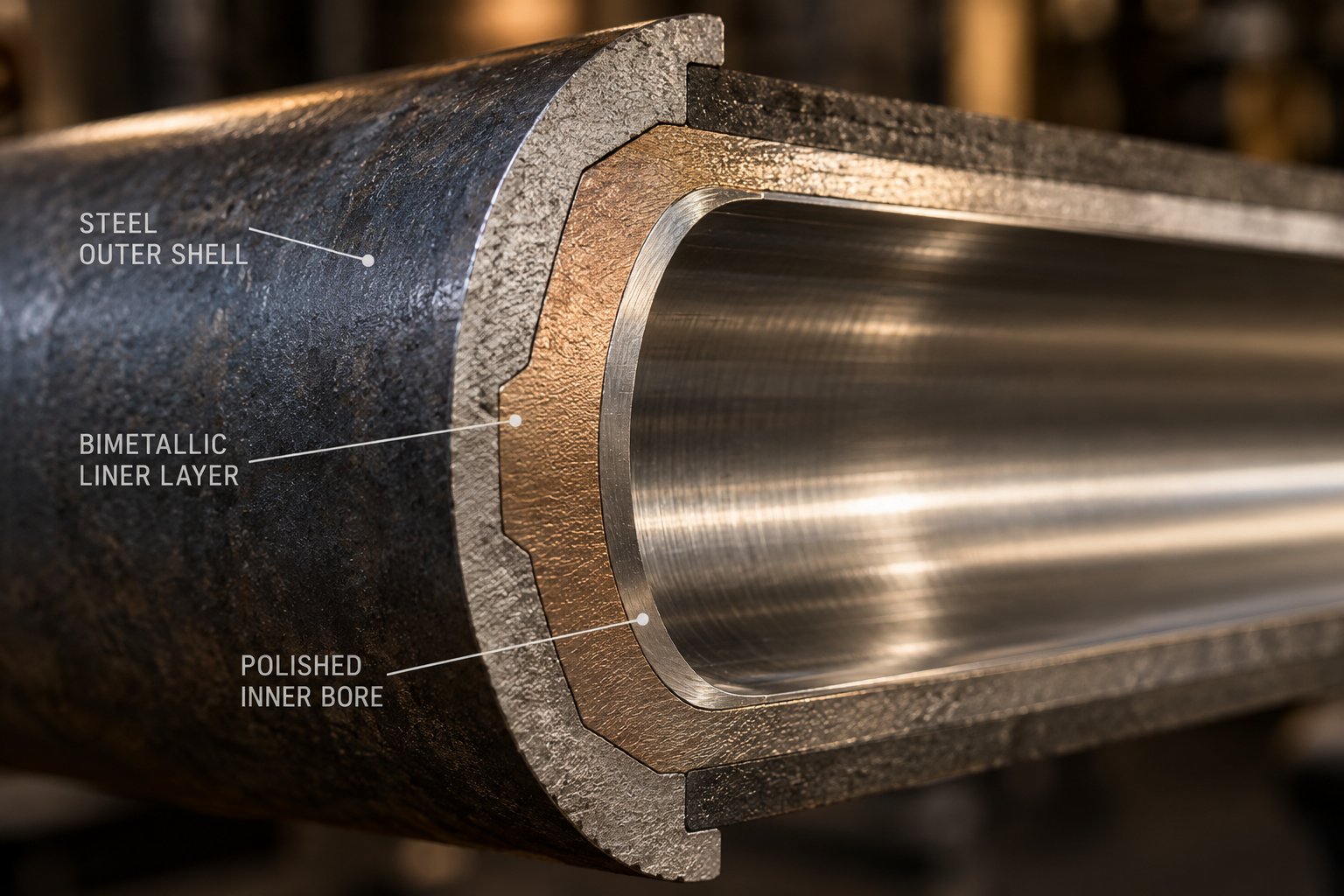
Barrel-screw clearance is another critical tolerance. Too tight, and metal-to-metal contact accelerates wear. Too loose, and excessive leakage flow across the flight tips reduces volumetric efficiency, undermines pressure generation, and degrades mixing quality. Typical diametral clearances run at roughly 0.1% to 0.2% of screw diameter for new assemblies. Barrel liner selection — whether nitrided steel, bimetallic centrifugally cast alloys, or specialized wear-resistant coatings — must match the abrasiveness and corrosiveness of the resins being processed.
These three zones and their barrel-side counterparts do not operate in isolation. Starve the feed zone, and the transition zone cannot develop sufficient shear to melt the polymer. Over-compress in the transition, and the metering zone receives degraded material. Misalign barrel temperatures, and even a perfectly designed screw geometry underperforms. This interdependence is precisely what transforms a simple screw/barrel design PDF specification into a multi-variable optimization problem — one where quantifying each parameter's effect on processing outcomes becomes essential.
Key Design Parameters and Their Processing Effects
Knowing what each zone does is one thing. Knowing exactly how a single geometric change in one zone ripples across output rate, melt temperature, and part quality is something else entirely. This is where screw barrel design shifts from descriptive anatomy to predictive engineering — and where most references fall short. They list parameters without connecting them to measurable processing consequences.
What you actually need is a cause-and-effect framework: change variable X, and here is what happens to outcomes Y and Z. That framework turns a screw barrel design for extruder applications — or any polymer process — from guesswork into structured decision-making.
Geometric Variables and Their Processing Impact
Six geometric variables define the behavior of any plasticating screw. Each one pulls multiple processing levers simultaneously, which is precisely why adjusting a single parameter in isolation often creates new problems while solving old ones.
L/D ratio sets the stage. A longer screw relative to its diameter provides more barrel length for heat transfer, shear work, and mixing. General-purpose thermoplastics typically run at 24:1 to 30:1, while filled compounds and specialty applications push toward 32:1 or even 36:1 for devolatilizing configurations. But length comes at a cost — literally. Longer screws demand higher torque, stiffer shafts to resist deflection, and more expensive barrel assemblies. They also extend residence time, which benefits slow-melting polymers but punishes thermally sensitive ones.
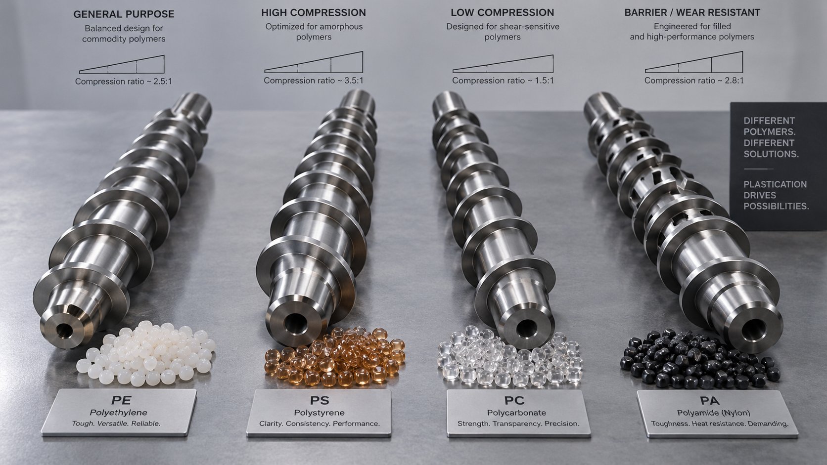
Compression ratio — feed channel depth divided by metering channel depth — controls how aggressively the screw works the material. The range spans roughly 1.5:1 to 4.5:1 across common thermoplastics. Low ratios (1.5:1 to 2.5:1) protect heat-sensitive materials like PVC and PVDF from shear-induced degradation. Medium ratios (2.5:1 to 3.5:1) suit general-purpose polyolefins, ABS, and PS. High ratios (3.5:1 to 4.5:1) deliver the intense compaction that crystalline polymers like nylon and PET require for complete melting. As Essentra Components notes, the higher the compression ratio, the greater the shear heat imparted to the resin — and the greater the potential for creating internal stresses in sensitive materials.
Channel depth in the feed zone determines volumetric intake capacity. Deeper channels accept more material per revolution, but excessive depth weakens the screw root and reduces the compressive force available for solids conveying. In the metering zone, channel depth governs output rate and backpressure. A shallow metering channel generates higher pressure and better mixing but increases shear stress — a critical balance for any barrel screw design.
Helix angle for a standard square-pitch screw sits at approximately 17.7 degrees, where pitch equals the screw's outer diameter. Opening the helix angle improves solids conveying efficiency by changing the force vector acting on pellets, but it reduces the number of effective flights along the barrel length. Modified helix angles appear in specialty configurations for powder processing and high-throughput film lines.
Flight width affects both the structural integrity of the screw and the leakage flow path. Wider flights provide more mechanical strength and a longer seal against the barrel wall, reducing leakage. Narrower flights maximize open channel area for higher volumetric capacity but sacrifice sealing effectiveness.
Flight clearance — the radial gap between the flight tip and the barrel bore — is one of the most underappreciated variables. Tight clearance minimizes backward leakage flow, preserving pumping efficiency. But as screws wear, this gap grows, and the resulting leakage reduces output while simultaneously raising melt temperature through additional shear work on the material flowing backward over the flight.
Design Trade-Offs Engineers Must Navigate
Every parameter adjustment in screw barrel design involves a trade-off — sometimes an obvious one, sometimes a hidden interaction that only reveals itself in production. Consider a few practical examples.
Increasing the L/D ratio gives you more residence time, better melting, and improved mixing thoroughness. Sounds like a win across the board. But that extended residence time becomes a liability for thermally sensitive resins that degrade when held at processing temperatures too long. You also pay for a longer barrel, higher motor torque to overcome increased drag, and a stiffer screw shaft to prevent deflection. Engineers evaluating screw barrel design software often discover that simulation reveals diminishing returns beyond a certain L/D threshold for their specific resin and throughput target.
Raising the compression ratio improves melt consistency for crystalline polymers that need aggressive energy input — but apply that same ratio to a shear-sensitive PVC compound, and you generate mechanical heat that no barrel temperature adjustment can remove. As one industry principle puts it: barrel heaters add heat that controllers can regulate, but shear heat from an overly aggressive screw geometry is baked into the design itself.
Deepening the feed channel boosts intake capacity, which seems straightforward for high-output applications. Yet a deeper feed zone paired with an unchanged metering depth raises the effective compression ratio — potentially overshooting what the polymer can tolerate. Meanwhile, reducing flight clearance improves pumping efficiency in a new screw, but specifying clearances that are too tight accelerates wear and shortens the interval before output quality begins to deteriorate.
These interconnections explain why experienced engineers rarely change one parameter without modeling the cascade effects on every other variable. The barrel screw design on knife-edge tolerances can mean the difference between consistent production and chronic defect chasing.
Quick-Reference Parameter Effects Table
The table below maps each geometric variable to its directional effect on six key processing outcomes. Use it as a quick-reference tool when evaluating an existing screw specification or specifying a new one. Arrows indicate the effect of increasing the parameter value.
| Geometric Parameter | Output Rate | Melt Temperature | Shear Stress | Residence Time | Mixing Quality | Pressure Generation |
|---|---|---|---|---|---|---|
| L/D Ratio (typical range: 20:1–36:1) | Moderate increase | Increases (more shear history) | Slight increase | Increases significantly | Improves substantially | Increases |
| Compression Ratio (typical range: 1.5:1–4.5:1) | Minimal direct effect | Increases (higher shear heat) | Increases significantly | Minimal direct effect | Improves melt uniformity | Increases in transition zone |
| Feed Channel Depth | Increases (more intake volume) | Minimal direct effect | Decreases in feed zone | Slight increase | Minimal direct effect | Minimal direct effect |
| Metering Channel Depth | Increases (more melt volume) | Decreases (lower shear) | Decreases significantly | Increases | Decreases (less shear mixing) | Decreases |
| Helix Angle (standard: ~17.7°) | Increases solids conveying | Minimal direct effect | Minimal direct effect | Slight decrease (fewer flights) | Slight decrease | Varies with zone |
| Flight Width | Slight decrease (less open channel) | Slight increase (more shear at tip) | Increases at flight land | Slight increase | Slight improvement (better seal) | Increases (reduced leakage) |
| Flight Clearance | Decreases (more leakage flow) | Increases (leakage shear heating) | Increases locally at flight tip | Increases (recirculation) | Decreases (back-mixing) | Decreases (pressure loss) |
A few patterns jump out of this table. Metering channel depth is the single most influential variable for output rate and pressure generation — which is why it appears in nearly every screw specification discussion. Compression ratio dominates shear stress and melt temperature effects, making it the critical variable for material-sensitive applications. And flight clearance, often treated as a maintenance metric rather than a design parameter, directly impacts four of the six processing outcomes.
Notice, too, that no single parameter improves all six outcomes simultaneously. Higher compression ratios improve melt uniformity but raise shear stress. Deeper metering channels increase output but sacrifice pressure and mixing. This is the fundamental reality of screw geometry: every design choice is a deliberate trade-off, and the right balance depends entirely on the polymer being processed and the application it serves.
That application dependency is exactly what makes the next question unavoidable — how do these parameter selections shift when you move from injection molding to single-screw extrusion, twin-screw compounding, or blow molding?
How Screw Barrel Design Differs Across Applications
A screw geometry optimized for continuous film extrusion will struggle inside an injection molding machine — and vice versa. The reason is simple: each process imposes fundamentally different demands on how polymer is melted, pressurized, and delivered. Cycle timing, output mode (batch versus continuous), melt homogeneity requirements, and shear sensitivity all shift depending on the application. Understanding these distinctions prevents costly mismatches and reveals why injection molding screw and barrel design follows a different logic than configurations built for extrusion or blow molding.
Injection Molding Screw Barrel Requirements
Injection molding operates in discrete cycles. The screw must plasticate a precise volume of polymer, build shot pressure, then act as a ram to inject melt into the mold cavity. This dual role — rotating plasticator and linear injector — creates requirements you won't find in any continuous process.
The reciprocating screw sits at the heart of this. During the plasticating phase, it rotates and retracts as melt accumulates ahead of it. During injection, it drives forward, pushing the shot through the nozzle. A non-return valve (check ring) at the screw tip prevents backflow during injection — and its design directly affects shot-weight consistency. A floating check ring rather than a ball check is generally recommended for smoother flow and less material hang-up.
Because the cycle is batch-based and speed matters, injection molding screws tend to be shorter than their extrusion counterparts. L/D ratios typically fall between 18:1 and 24:1, with zone proportions often split at roughly 50% feed, 25% compression, and 25% metering. Compression ratios between 2:1 and 3:1 suit the broad range of commodity and engineering thermoplastics processed on general-purpose machines. The shorter overall length reflects the fact that rapid plasticating — not extended melting residence — drives productivity.
Barrel configuration mirrors these priorities. Fewer heating zones (typically three to four) align with the shorter barrel, and precise temperature control near the nozzle prevents drool or freeze-off between shots.
Extrusion and Blow Molding Design Distinctions
Single-screw extrusion flips the priorities. Continuous output stability, not cycle speed, dominates. Longer L/D ratios — commonly 24:1 to 30:1, sometimes reaching 36:1 for specialty applications — provide the extended residence time needed for thorough, consistent melting at high throughput rates. Barrier screw designs, which add a secondary flight to physically separate the solid bed from the melt pool, significantly improve melting efficiency and reduce temperature variation in the extrudate.
Blow molding screw barrel specifications sit in their own category. Whether you're running extrusion blow molding (EBM) or injection blow molding (IBM), the end goal is a parison or preform with exceptionally uniform wall thickness and minimal thermal variation. Uneven melt temperature translates directly into weak spots, cloudy surfaces, or inconsistent bottle weight.
To achieve that homogeneity, blow molding screws often feature L/D ratios between 24:1 and 30:1 and compression ratios around 3.5:1 — higher than typical injection molding configurations. The longer geometry gives the polymer more time to melt and mix, while the elevated compression ratio builds the pressure needed for a smooth, bubble-free parison. Keeping shear relatively controlled remains critical, though, because excessive shear orientation in the melt can cause uneven stretching during the blowing phase.
Compared to the old screw on top barrel design concepts that treated all processes identically, modern blow molding configurations use deeper feed channels, gradual tapers, and dedicated mixing sections near the screw tip to deliver the melt uniformity these applications demand.
Single-Screw Versus Twin-Screw Architecture
Twin-screw extrusion represents an entirely different design philosophy. Instead of a monolithic screw with fixed zone geometries, twin-screw extruder barrel design relies on modular screw elements assembled on a common shaft. This modularity lets engineers reconfigure the screw profile for each formulation without machining a new screw.
Three element types form the building blocks, as detailed in NC State Extension research on screw profile design:
- Conveying elements — deep-flighted sections that move material forward with minimal shear input, ideal for feeding and transport zones
- Kneading elements — staggered disc blocks that perform dispersive mixing (breaking agglomerates) or distributive mixing (spreading additives evenly), depending on disc width and stagger angle
- Mixing and reverse elements — toothed elements for gentle blending and left-handed elements that push material backward, creating restriction points that increase shear and residence time locally
The arrangement logic follows a clear pattern. Conveying elements dominate the feed section, kneading blocks cluster around the melting and mixing zones, and narrower-pitch conveying elements handle final pressurization before the die. Forward kneading elements are less aggressive, neutral elements increase residence time, and reverse kneading blocks generate maximum shear restriction. By rearranging these modular pieces, a single twin-screw extruder can process anything from color masterbatch to glass-fiber-reinforced compounds — something no fixed single-screw geometry can match.
The comparison table below summarizes how these application-driven requirements translate into concrete parameter differences:
| Parameter | Injection Molding | Single-Screw Extrusion | Twin-Screw Extrusion | Blow Molding |
|---|---|---|---|---|
| L/D Ratio | 18:1 – 24:1 | 24:1 – 36:1 | 32:1 – 52:1 (modular) | 24:1 – 30:1 |
| Compression Ratio | 2:1 – 3:1 | 2.5:1 – 4:1 | N/A (element-based) | 3:1 – 3.5:1 |
| Output Mode | Batch (shot cycle) | Continuous | Continuous | Continuous or intermittent |
| Typical Screw Features | Non-return valve, general-purpose flights | Barrier flights, mixing heads (Maddock, pineapple) | Modular conveying, kneading, and reverse elements | Deep feed channels, gradual taper, mixing sections |
| Barrel Configuration | 3–4 heating zones, short barrel | 4–6+ zones, extended barrel with optional venting | Segmented barrel with individual zone control, side feeders, vent ports | 4–5 zones, tight temperature control for parison uniformity |
| Primary Design Priority | Fast plasticating, consistent shot weight | Stable continuous output, melt consistency | Flexible mixing intensity, formulation versatility | Melt homogeneity, low shear orientation |
One pattern stands out clearly: the polymer's journey through the barrel must be engineered to match not just the resin's properties, but the specific mechanical and thermal demands of the process itself. An injection mold demands speed and shot precision. An extruder demands steady-state stability. A blow molder demands thermal uniformity above almost everything else. And a twin-screw compounder demands the flexibility to reconfigure for entirely different formulations.
Yet even within a single application category, screw geometry cannot be finalized until you answer a more fundamental question — which polymer family are you processing? The rheological and thermal fingerprint of each resin type imposes its own set of non-negotiable constraints on compression ratio, channel depth, and special design features.
Polymer-Specific Screw Barrel Design Recommendations
The previous section showed that application type — injection molding, extrusion, blow molding — reshapes screw geometry requirements. But within any single application, the polymer you feed into the hopper rewrites the rules again. A screw barrel design for polyethylene follows different logic than one built for PVC, and running glass-filled nylon through a general-purpose polyolefin configuration is a recipe for premature wear and broken fibers. Polymer specific screw design recommendations must start with the resin's rheological and thermal fingerprint, then translate those characteristics into concrete geometric choices.
Polyolefin and Styrenic Screw Geometry Recommendations
Polyolefins and styrenics represent the highest-volume resin families in plastics processing, yet their melting behaviors diverge in ways that demand different screw configurations.
HDPE and LDPE are semicrystalline polymers with significant latent heat of fusion — LDPE, for example, requires roughly 293 J/g of melt enthalpy. That crystalline energy barrier means these resins benefit from moderately high compression ratios (typically 2.5:1 to 3.5:1) and barrier screw designs that separate the melt pool from the solid bed, ensuring complete plastication before the metering zone. HDPE's higher crystallinity and sharper melting point push it toward the upper end of that compression range, while LDPE's broader melting transition tolerates slightly lower ratios. Both benefit from L/D ratios of 24:1 to 30:1 in extrusion applications, providing sufficient barrel length for the energy-intensive melting these polymers require.
Polypropylene behaves similarly to HDPE in many respects — semicrystalline, requiring substantial melt energy — but its lower melt viscosity at processing temperatures means metering zone channel depths can be slightly deeper without sacrificing pressure generation. PP also responds well to barrier flights and distributive mixing elements for applications demanding tight color dispersion or additive uniformity.
Styrenics (PS, HIPS, ABS) are amorphous, which fundamentally changes the melting equation. Without a crystalline phase transition, these materials soften gradually rather than melting sharply. Compression ratios for PS and HIPS typically land around 2.5:1 to 3.0:1 — industry convention often cites approximately 3.0 for HIPS. ABS, with its rubber-modified structure, benefits from slightly lower ratios and gentler compression transitions to avoid excessive shear that can degrade the rubber phase and compromise impact properties. Experimental data comparing general-purpose and fractal screw designs have shown that HIPS produces roughly 30% higher mass flow rates than LDPE at equivalent screw speeds, driven largely by its higher melt density — a factor engineers should account for when sizing metering zones.
PVC and Heat-Sensitive Polymer Design Constraints
If polyolefins and styrenics are forgiving, PVC is anything but. Screw barrel design for PVC processing must respect an unusually narrow thermal window where the material is processable but not yet degrading. PVC's high melt viscosity and pronounced thermal sensitivity make it prone to degradation during extrusion, releasing hydrochloric acid that corrodes metal surfaces and generates black specks in the product.
These characteristics impose several non-negotiable design constraints:
- Low compression ratios — typically 1.5:1 to 2.5:1 — minimize shear-generated heat that pushes temperatures past the degradation threshold. Research on twin-screw PVC extrusion has confirmed that lower compression ratios enhance throughput while reducing melt temperature, directly lowering degradation risk.
- Controlled barrel temperatures — PVC processing often uses a declining temperature profile from the kneading section toward the die. ANSYS Polyflow simulations of counter-rotating twin-screw PVC extrusion maintained barrel temperatures at 200 degrees C in the kneading zone and 160 degrees C in the compressing and mixing sections to prevent thermal runaway.
- Corrosion-resistant metallurgy — the HCl released during any localized degradation attacks standard tool steel, demanding chrome or nickel-alloy barrel liners and hardened screw coatings.
- Streamlined flow paths — dead spots in screw geometry trap material, extending local residence time and virtually guaranteeing degradation. Screw tip designs must avoid recesses where PVC can stagnate.
Other heat-sensitive polymers — PVDF, certain TPUs, and bioplastics like PLA — share PVC's intolerance for excessive shear and residence time, though none match its corrosive behavior. For these materials, the guiding principle remains the same: minimize mechanical energy input through conservative compression ratios and move material through the barrel quickly.
Engineering Plastics and Filled Compound Considerations
Engineering thermoplastics like nylon (PA6, PA66), POM, and PEEK occupy the opposite end of the thermal spectrum. Their high melting points, elevated melt viscosities, and — for semicrystalline grades — sharp crystalline transitions demand aggressive energy input during plastication.
Nylon typically processes well with compression ratios from 3.0:1 to 4.0:1 and L/D ratios of 20:1 to 24:1 in injection molding, or 24:1 to 28:1 in extrusion. Its strong moisture sensitivity requires proper drying before processing, but from a screw geometry standpoint, the primary challenge is delivering enough shear energy to fully melt the crystalline structure without creating excessive melt temperature that causes oxidation or yellowing. PEEK, with processing temperatures exceeding 380 degrees C, demands not only high compression ratios but also barrel and screw materials rated for sustained high-temperature operation.
Filled and reinforced compounds introduce a completely different design challenge. When you add glass fibers, mineral fillers, or carbon fiber to a base polymer, the abrasive particles act like sandpaper on flight surfaces and barrel walls. Screw design for glass filled compounds must address two simultaneous problems: protecting the hardware from accelerated wear and protecting the fibers from excessive breakage.
Research presented at the 37th International Conference of the Polymer Processing Society demonstrated that compression ratio has a significant and direct effect on fiber length degradation in glass-fiber-reinforced polypropylene. Higher compression ratios produced measurably shorter fibers — and since mechanical properties like tensile strength and impact resistance correlate directly with retained fiber length, this finding has real engineering consequences. The researchers developed an optimized screw with adjusted zone lengths, modified flight depths, and tuned pitch that reduced fiber breakage compared to standard three-zone designs, demonstrating that gentler plasticating configurations preserve fiber integrity.
For filled compounds, the practical guidelines are clear:
- Use moderate compression ratios (2.0:1 to 2.5:1) to reduce shear forces on fibers
- Specify deeper channels in the metering zone to lower shear rates
- Consider downstream side-feeding on twin-screw extruders so fibers enter the already-molten polymer rather than being subjected to the full compression cycle
- Select bimetallic barrel liners and hardened flight surfaces rated for abrasive service
The table below consolidates polymer specific screw design recommendations across these resin families:
| Polymer Family | Compression Ratio Range | L/D Ratio Guidance | Channel Depth Considerations | Special Design Features |
|---|---|---|---|---|
| HDPE / LDPE | 2.5:1 – 3.5:1 | 24:1 – 30:1 (extrusion); 20:1 – 24:1 (injection) | Deep feed for high bulk density pellets; moderate metering depth | Barrier flights for melting efficiency; distributive mixing heads |
| PP | 2.5:1 – 3.5:1 | 24:1 – 28:1 (extrusion); 20:1 – 24:1 (injection) | Slightly deeper metering zone tolerable due to lower melt viscosity | Barrier screws; mixing elements for color/additive dispersion |
| PS / HIPS | 2.5:1 – 3.0:1 | 24:1 – 30:1 | Standard depths; amorphous melting requires less aggressive compression | General-purpose or barrier designs; avoid excessive shear on HIPS rubber phase |
| ABS | 2.0:1 – 2.8:1 | 22:1 – 26:1 | Moderate depths; gradual taper to protect rubber phase | Low-shear transitions; vented barrels for moisture-sensitive grades |
| PVC | 1.5:1 – 2.5:1 | 16:1 – 24:1 | Shallow metering to limit shear heat; streamlined flow paths | Corrosion-resistant metallurgy; no dead spots; declining temperature profiles |
| Nylon (PA6/PA66) | 3.0:1 – 4.0:1 | 20:1 – 28:1 | Standard feed; shallow metering for pressure and shear energy | High-compression transitions for crystalline melting; vented barrels recommended |
| PEEK | 2.5:1 – 3.5:1 | 24:1 – 30:1 | Moderate depths; high-temperature-rated screw metallurgy required | High-temp barrel liners; controlled residence time to prevent degradation |
| Glass-Filled Compounds | 2.0:1 – 2.5:1 | 20:1 – 26:1 | Deeper metering channels to reduce shear on fibers | Wear-resistant bimetallic liners; downstream fiber feeding; gentle compression taper |
A pattern emerges from this mapping. Crystalline polymers push compression ratios higher. Heat-sensitive resins pull them lower. Filled compounds demand a parallel conversation about metallurgy and fiber preservation that goes beyond geometry alone. And that metallurgy conversation — which materials the screw and barrel themselves are made from, and what surface treatments protect them — is exactly where many screw specifications succeed or fail in the field.
Material Selection and Surface Treatment Strategy
You can perfect every geometric parameter — nail the compression ratio, dial in channel depths, specify the ideal L/D — and still watch your screw barrel system fail prematurely if the metallurgy cannot handle the resin you are running. This is the uncomfortable truth that separates a specification on paper from one that survives in production. A screw barrel material selection guide must address three distinct layers: the base metal that provides structural integrity, the liner or coating that protects working surfaces, and the surface treatments that fine-tune wear and corrosion resistance for specific processing environments.
Screw Base Metal and Barrel Liner Options Compared
Think of base metal selection as choosing the skeleton of your system. It needs to resist bending under torque, maintain dimensional stability at processing temperatures, and provide a suitable foundation for whatever protective layer sits on top.
Nitrided steel is the workhorse for general-purpose applications. Standard 4140 or 4340 alloy steel, nitrided to produce a hard case layer (typically 55–70 HRC surface hardness), offers a cost-effective solution for processing clean commodity resins like unfilled polyolefins, styrenics, and standard ABS. Nitrided screw barrel specifications typically call for a case depth of 0.3 to 0.5 mm — enough to resist abrasion from non-filled polymers over reasonable service intervals, but insufficient for heavily loaded compounds.
Tool steels step up when demands intensify. D2, a high-carbon, high-chromium cold-work steel, delivers excellent abrasion resistance and moderate corrosion protection — useful for mineral-filled compounds. H13, a hot-work tool steel, maintains hardness and toughness at elevated temperatures, making it the preferred choice for engineering plastics processed above 300 degrees C. Both carry a significant cost premium over nitrided alloy steels but extend service life considerably in demanding applications.
High-alloy steels and specialty grades — including Hastelloy and Inconel variants — target the most aggressive environments: halogenated polymers that release corrosive gases, fluoropolymers processed at extreme temperatures, or recycled streams with unpredictable contamination profiles.
On the barrel side, the liner is what takes the beating. Three primary options dominate:
- Nitrided barrels — the economical baseline for non-abrasive resins, offering surface hardness comparable to nitrided screws but limited depth of protection
- Bimetallic centrifugally cast liners — a wear-resistant alloy (typically iron-boron or nickel-based) is spun into the barrel bore, creating a protective layer 1.5 to 3 mm thick that dramatically extends service life for abrasive compounds. As practical bimetallic selection guidance emphasizes, the alloy choice should be matched to whether the primary threat is abrasion, corrosion, or both
- Tungsten carbide coatings — applied via thermal spray processes, these offer extreme hardness for the most abrasive applications but at a premium cost and with limitations on repairability
The useful distinction in bimetallic barrel liner design is not just the alloy composition — it is whether the protection addresses abrasion resistance, corrosion resistance, or a balanced combination. Iron-boron alloys excel at resisting mineral and glass-fiber abrasion. Nickel-based alloys provide superior corrosion resistance for PVC and fluoropolymer processing. Specifying the wrong alloy family leaves your barrel vulnerable to the exact failure mode you were trying to prevent.
Surface Treatment Selection Criteria
Beyond base metals and liners, surface treatments add a final layer of targeted protection. These are not alternatives to proper base metal selection — they are complements that address specific failure mechanisms.
- Chrome plating — provides a smooth, corrosion-resistant surface that also reduces polymer adhesion. Commonly applied to screws processing PVC or other corrosive resins, chrome plating improves cleanability and resists the HCl attack that degrades unprotected steel. However, chrome offers limited abrasion resistance, so it is not a substitute for harder base metals in filled-compound applications.
- PVD (Physical Vapor Deposition) coatings — thin-film coatings like TiN, CrN, or DLC (diamond-like carbon) deliver hardness values exceeding 2000 HV in layers just a few microns thick. These screw barrel surface treatment options reduce friction, resist adhesive wear, and can be applied to complex geometries. Their thin profile means they don't alter screw-to-barrel clearances significantly — an advantage during retrofits.
- Specialized corrosion-resistant alloys — weld-overlay techniques using Stellite or nickel-chromium alloys protect high-wear areas like flight tips and check-ring seats. These targeted applications concentrate expensive material only where it is needed most, balancing cost against protection.
Matching Materials to Processing Conditions
The real challenge is not knowing that these options exist — it is knowing which combination to specify for your particular processing scenario. The decision depends on four variables: how abrasive your resin is, how corrosive it is, what temperature you are processing at, and how many hours per year the system will run.
The decision matrix below maps common processing scenarios to recommended material combinations:
| Processing Scenario | Primary Threat | Recommended Screw Material | Recommended Barrel Solution | Surface Treatment |
|---|---|---|---|---|
| General-purpose commodity resins (unfilled PE, PP, PS) | Mild abrasion | Nitrided 4140/4340 steel | Nitrided barrel | Optional chrome for easier cleaning |
| Abrasive filled compounds (glass fiber, mineral fillers, GF-PP) | Severe abrasion | D2 tool steel or bimetallic flight facing | Bimetallic liner (iron-boron alloy) | Stellite flight-tip overlay |
| Corrosive halogenated polymers (PVC, PVDF, fluoropolymers) | Chemical corrosion | H13 tool steel with chrome plating | Bimetallic liner (nickel-based alloy) | Chrome plating or nickel alloy overlay |
| High-temperature engineering plastics (PEEK, PEI, high-temp nylon) | Thermal fatigue and wear | H13 or high-alloy steel | Bimetallic liner rated for sustained high temps | PVD coating for friction reduction |
| Recycled streams with contamination | Abrasion and scoring from unknowns | D2 tool steel | Bimetallic liner (iron-boron or balanced alloy) | PVD or chrome depending on resin type |
The cost-performance trade-offs become clear when you look at this matrix through an economic lens. Nitrided barrels and standard alloy screws cost the least upfront and perform perfectly well for unfilled commodity resins that impose minimal wear. Running those same components on 30% glass-filled nylon, however, might cut service life from 18 months to as little as 3–4 months — meaning frequent replacements quickly eclipse the initial savings. A bimetallic liner with hardened flight surfaces costs more at purchase but may deliver three to five times the operational life in abrasive service, making it the lower total-cost option over a multi-year production run.
Similarly, chrome plating a screw for general-purpose PE processing is overkill — it adds cost without meaningful benefit. But skip that same chrome plating on a PVC line, and corrosion-driven degradation introduces black specks and dimensional loss that compromise both product quality and barrel longevity.
Matching these material decisions to your specific polymer, filler package, temperature profile, and production schedule is precisely where specialized manufacturers add value. NANHAIYA's custom screw design services exemplify this approach — tailoring not just screw geometry and barrel configuration but also material selection and surface treatment to each processor's specific resin, output targets, and operational conditions. Rather than defaulting to a generic upgrade, this kind of application-matched specification ensures that every dollar spent on metallurgy addresses a real processing need.
Still, even the best material combination cannot rescue a screw geometry built on faulty calculations. The mathematical relationships that underpin compression ratios, volumetric output, and shear rates form the quantitative backbone of every specification decision — and understanding their structure separates informed engineering from educated guessing.
Screw Barrel Design Calculations: The Math Behind the Geometry
Every parameter discussed so far — compression ratio, channel depth, L/D ratio — ultimately reduces to a number. And that number is not arbitrary. It comes from a mathematical relationship that connects screw geometry to polymer behavior. Understanding these formulas does not require advanced calculus, but it does require knowing what each calculation actually tells you and how shifting one input variable cascades through the result. These screw barrel design calculations form the quantitative backbone that separates a reasoned specification from a guess.
Compression Ratio and L/D Ratio Calculations
Two ratios define the broadest strokes of any screw specification. The compression ratio formula in screw design is straightforward:
Compression Ratio (C) = Feed Channel Depth (Hf) / Metering Channel Depth (Hm)
A feed depth of 8 mm paired with a metering depth of 3 mm yields a compression ratio of approximately 2.67:1. Simple division — but the engineering significance runs deep. This single number governs how aggressively the screw compacts and shears the polymer during melting. Experimental extrusion research by Dow Inc. demonstrated that for LLDPE pellets, a compression ratio of 2.8 proved optimal — screws at 2.0 could not develop adequate channel pressure at low speeds, while screws at 3.2 and 3.6 produced solid polymer fragments in the extrudate at higher screw speeds due to excessive solids conveying overwhelming the melting capacity.
A closely related metric, the compression rate, accounts for how quickly that compression happens across the transition section:
Compression Rate (R) = (Hf - Hm) / (Number of Turns in Transition Section x Hm)
Why does this matter separately from the compression ratio itself? Because two screws with identical compression ratios but different transition lengths will apply that compression at very different rates — one gradually, the other abruptly. Abrupt compression can fracture the solid bed prematurely, while too-gradual compression fails to generate the pressure needed for efficient melting.
The L/D ratio screw barrel calculation is equally direct:
L/D Ratio = Flighted Length of Screw / Nominal Screw Diameter
A 90 mm diameter screw with 2,250 mm of flighted length gives a 25:1 L/D ratio. This number tells you how much barrel real estate is available for melting, mixing, and pressure development. Increase it, and you extend residence time and improve homogenization — but you also raise torque requirements and capital cost. Decrease it, and you shorten the thermal and mechanical history the polymer experiences, which benefits heat-sensitive materials but risks incomplete melting for crystalline resins.
Output and Shear Rate Mathematical Models
Where compression and L/D ratios describe static geometry, the screw barrel volumetric output formula describes dynamic performance — how much polymer actually moves through the system. The classical model decomposes metering zone throughput into three competing components:
Qtotal = Qdrag - Qpressure - Qleakage
Drag flow (Qdrag) is the forward-pumping action created by screw rotation against the barrel wall. It is proportional to screw speed, channel width, channel depth, and the velocity component along the channel helix. Pressure flow (Qpressure) works in opposition — the backpressure imposed by the die and screen pack pushes melt backward through the channel, reducing net output. Leakage flow (Qleakage) represents material escaping backward over the flight tips through the radial clearance gap.
In practical terms, this means output is not simply a function of screw speed. Increase die restriction, and the pressure-flow term grows, reducing net throughput even at constant RPM. Let flight clearance widen through wear, and the leakage term increases, further eroding pumping efficiency. This three-component model explains why worn screws produce less output at the same speed — the leakage pathway has expanded.
Shear rate in the metering channel connects screw speed and geometry to the mechanical forces acting on the polymer. The first-order estimate, as detailed in TA Instruments' technical analysis, follows a drag-flow approximation:
Shear Rate (ȳ) = Vbz / H
Here, Vbz is the barrel velocity component in the down-channel direction and H is the metering channel depth. The barrel surface speed itself is calculated as V = piDN/60, where D is barrel diameter in meters and N is screw speed in RPM. That velocity is then projected along the channel helix angle to yield Vbz.
Consider what this relationship reveals. Shear rate is inversely proportional to channel depth — halve the metering depth, and you double the shear rate at the same screw speed. For shear-sensitive polymers, this interaction is critical: an overly shallow metering channel does not just increase pressure; it imposes mechanical stress that can degrade the resin. TA Instruments' worked example for a 60 mm barrel at 100 RPM with a 5 mm channel depth and 17-degree helix angle produces a shear rate of approximately 60 s-1 — a moderate value typical for many metering-section operations and substantially lower than what the same melt would experience in a restrictive die land or small gate.
From Hand Calculations to Design Specifications
These formulas are not academic exercises. They form the starting point for every screw specification. An engineer sizing a new screw begins by selecting a target compression ratio based on the polymer family, choosing an L/D ratio that balances melting needs against residence time limits, and then verifying that the resulting shear rates and output predictions align with production targets. The volumetric output model identifies whether the proposed geometry can deliver the required throughput against the expected die backpressure. The shear rate calculation flags whether the metering channel will overstress a sensitive resin.
What hand calculations cannot do is account for the full complexity of non-Newtonian flow behavior, temperature-dependent viscosity changes along the barrel, and the interaction between melting dynamics and pressure development. That is where computational tools take over — refining the initial design envelope these formulas establish. But without sound hand calculations as a starting point, simulation has nothing meaningful to optimize.
These mathematical relationships also serve a diagnostic role. When a running process shows symptoms — output falling short of predictions, melt temperature running higher than expected, or pressure profiles deviating from targets — the same formulas help trace those symptoms back to their geometric root causes.
Troubleshooting Processing Defects Through Screw Barrel Design
Here is something most troubleshooting guides won't tell you: many persistent processing defects are not process problems at all — they are design problems wearing a process mask. You can adjust barrel temperatures, tweak screw speed, and fine-tune backpressure all day, but if the screw geometry itself is the root cause, those adjustments only paper over symptoms. A true screw barrel design troubleshooting guide traces each defect backward through the physics until it lands on a specific geometric parameter that needs to change.
That is exactly what this section delivers — a defect-to-design framework that connects what you see at the die to what is happening inside the barrel.
How Design Parameters Create Processing Defects
Imagine running a production line where melt temperature swings by 10 to 15 degrees between samples, even though your barrel heater controllers show rock-steady setpoints. You replace thermocouples. You recalibrate controllers. The variation persists. Why? Because the temperature inconsistency is not coming from the heaters — it is coming from insufficient residence time in a screw with an L/D ratio too short for the polymer's melting requirements. The melt exits the metering zone before temperature has fully homogenized across the channel cross-section.
This pattern repeats across every common defect category. The visible symptom appears downstream — at the die, in the part, or on the product surface — but the geometric cause lives upstream in the screw channel. Consider the most frequent offenders:
- Inconsistent melt temperature — often traced to an inadequate L/D ratio that does not provide enough barrel length for thermal equalization, or an incorrect compression ratio that generates uneven shear heating across the channel width
- Unmelted particles or gels — typically caused by insufficient shear in the transition zone, excessive channel depth that allows solid polymer to bypass the melt film, or an absence of barrier flights that would separate solids from the melt pool
- Polymer degradation and black specks — linked to excessive residence time from oversized channels, dead spots in flight geometry where material stagnates, or flight clearances so worn that recirculating leakage flow subjects polymer to repeated shear cycles
- Surging output — frequently rooted in improper metering zone design that fails to generate adequate pressure, or feed zone geometry that creates inconsistent solids conveying
- Poor color or additive dispersion — the direct result of insufficient mixing capability, whether from the absence of distributive mixing elements or a metering zone too short to homogenize the melt
Each of these links follows a clear cause-and-effect chain grounded in the physics discussed throughout this article. The transition zone's compression ratio determines melting intensity. The metering zone's channel depth governs shear rate and pressure. The L/D ratio sets the total time available for heat transfer and mixing. When any of these parameters mismatches the polymer's requirements, defects emerge — and no amount of process-parameter tweaking will eliminate them permanently.
Defect-to-Design Root Cause Mapping
The table below functions as a screw barrel design defects solutions reference. For each common defect, it identifies the most probable geometric root causes and the corrective design modifications that address them. Use it as a diagnostic starting point: when a defect persists despite process adjustments, look to these design parameters for the underlying explanation.
| Processing Defect | Probable Design Root Cause | Recommended Design Modification |
|---|---|---|
| Inconsistent melt temperature | L/D ratio too short for polymer; compression ratio mismatched to resin crystallinity; insufficient barrel heating zones | Increase L/D ratio for extended thermal history; adjust compression ratio to match polymer's melting behavior; add barrel zones for finer temperature profiling |
| Unmelted particles / gels | Transition zone too short or too gradual; excessive channel depth in compression zone; no barrier flights to separate solids from melt | Steepen compression taper or extend transition zone length; reduce channel depth to increase shear; add barrier flights to prevent solid bed bypass |
| Polymer degradation / black specks | Oversized channels extending residence time; dead spots in screw tip or check valve geometry; excessive flight clearance causing recirculating shear | Reduce channel depths to shorten residence time; redesign screw tip to eliminate stagnation zones; replace worn screw to restore proper flight clearance |
| Output surging | Metering zone too shallow or too short to build stable pressure; feed zone geometry causing inconsistent solids conveying; improper feed section temperature control due to screw or barrel design | Lengthen or deepen metering zone for stable pressure generation; optimize feed zone channel depth and barrel surface condition (grooved bore); ensure screw cooling passages extend through entire solids conveying section |
| Poor color / additive dispersion | No dispersive or distributive mixing elements; metering zone too short for adequate melt homogenization; flight clearance too tight for cross-channel mixing | Add mixing sections (Maddock, pineapple, or kneading elements); extend metering zone length; consider mixing-head retrofit at screw tip |
| Excessive melt temperature | Compression ratio too high for resin's shear sensitivity; metering channel too shallow, driving shear rate beyond acceptable range | Reduce compression ratio; deepen metering channel to lower shear rate; consider barrier design that reduces shear while maintaining melting efficiency |
| Short shots / incomplete filling (injection molding) | Check valve wear allowing backflow; metering zone unable to generate sufficient injection pressure; feed zone starving downstream sections | Replace or redesign non-return valve; optimize metering depth for pressure generation; verify feed zone channel depth matches pellet bulk density |
Corrective Design Modifications for Common Problems
A few patterns in this mapping deserve closer attention because they reveal how melt quality screw barrel optimization actually works in practice.
Surging deserves special scrutiny because its root causes span all three screw zones — and even extend to barrel-side thermal management. As Mark Spalding of Dow Inc. documented in detailed case studies, the most common root cause of flow surging in smooth-bore extruders is improper temperature at the solids conveying surfaces. In one case involving an 8-inch two-stage extruder, surging occurred because the screw cooling passage was too short — extending only 4 diameters past the feed pocket when the solids conveying section was 7 diameters long. The screw ran too hot, disrupting the balance of forwarding and retarding frictional forces that drive stable solids conveying. The fix was a design change: extending the cooling bore to cover the full conveying length. In a second episode on the same machine, the feed casing cooling channels had occluded with mineral deposits, again overheating the solids conveying zone. Both cases illustrate a critical point — screw barrel design for consistent output must account for thermal management features, not just channel geometry.
Degradation and black specks follow a different but equally instructive pattern. As extrusion troubleshooting research confirms, high residence times cause polymer breakdown and gel formation — and residence time is fundamentally a design variable. Oversized channel volumes hold material in the barrel longer than necessary. Dead spots at flight transitions, in check-valve recesses, or behind mixing elements trap material indefinitely, subjecting it to continuous thermal exposure. The corrective approach targets both geometry (streamlining flow paths, eliminating recesses) and material selection (polished surfaces that prevent adhesion and stagnation).
Dispersion failures are perhaps the most straightforward to diagnose through this design lens. If your screw has no dedicated mixing section — no Maddock mixer, no pineapple head, no kneading blocks — then you are relying entirely on the shear field in the metering channel to distribute colorants and additives. For many resins and pigment loadings, that is simply not enough. Adding a dispersive or distributive mixing element near the screw tip can transform color uniformity without changing any other process parameter. In twin-screw configurations, this is where kneading element arrangement becomes critical — wider kneading blocks promote dispersive mixing that breaks down agglomerates, while narrower elements spread the dispersed phase more evenly.
The unifying principle across all these defect-design connections is that geometry is not neutral. Every channel depth, every flight angle, every clearance tolerance actively shapes how the polymer behaves — and misbehaves. When you view defects through this design lens rather than chasing process settings, you move from reactive troubleshooting to proactive engineering. And that proactive approach increasingly relies on computational tools that can predict these interactions before a single pellet enters the barrel.

Computational Tools and the Future of Screw Barrel Design Optimization
Predicting defects through geometry is powerful — but imagine verifying those predictions digitally before committing to steel. That is precisely what modern screw barrel design software tools and simulation platforms deliver. The era of machining a screw, running trial batches, discovering problems, and iterating through expensive physical prototypes is giving way to computational screw barrel design analysis that resolves geometry questions on screen rather than on the production floor.
Simulation and Computational Design Tools
CAE (Computer-Aided Engineering) flow simulation has matured dramatically for polymer processing. Dedicated platforms model the entire plasticating process — solids conveying, melting progression, melt pumping, and mixing — using the same fluid mechanics equations that govern real polymer behavior. Tools like Moldex3D, for instance, leverage the continuity, momentum, and energy equations combined with viscosity models such as the Cross-WLF model to predict how shear rate and temperature interact throughout the barrel. These are not simplified approximations; they capture the shear-thinning, temperature-dependent nature of real polymer melts.
What makes screw barrel design simulation optimization practical is the type of outputs these tools generate. Each output directly informs a specific design decision:
- Pressure profiles along screw length — reveal whether the transition zone builds sufficient compressive force for melting and whether the metering zone generates adequate die-entry pressure. A predicted pressure deficit at the screw tip signals the need for a shallower metering channel or extended metering length.
- Temperature distribution maps — expose hot spots caused by excessive shear and cold regions where melting is incomplete. These maps often uncover problems invisible to thermocouple readings, which measure barrel wall temperature rather than the melt core.
- Shear rate mapping — identifies zones where the polymer experiences mechanical stress beyond its processing tolerance. For shear-sensitive materials like PVC or rubber-modified ABS, this output is critical for validating that compression ratios and channel depths remain within safe limits.
- Residence time distribution (RTD) — quantifies how long different fractions of the melt spend inside the barrel. A broad RTD indicates that some material passes through quickly while other fractions linger — the exact condition that produces degradation and gels in heat-sensitive resins.
Finite element analysis (FEA) complements flow simulation by addressing the mechanical side of the design. FEA models predict screw deflection under torque loads, stress concentrations at flight roots, and thermal expansion that alters barrel-screw clearances at operating temperature. These structural insights prevent mechanical failures that no amount of flow optimization can foresee.
Research published in Polymers demonstrated just how impactful calibrated simulation can be. A study at National Cheng Kung University showed that by incorporating machine-response time constants into Moldex3D simulations, the error between simulated and experimental injection speed was reduced from 20% to just 6%, and V/P switchover point error dropped from 11% to 5%. These calibrated simulations enable what the researchers call "T0 mass production" — the ability to move from first trial to full-scale production without iterative mold trials. The same calibration logic applies to screw design: validated simulation parameters reduce the gap between predicted and actual screw performance.
Industry 4.0 Monitoring and Data-Driven Optimization
Simulation optimizes the design before it enters production. Industry 4.0 screw barrel monitoring optimizes the design during and after production — creating a feedback loop that no previous generation of polymer processing technology could achieve.
Sensor-equipped barrels now routinely capture real-time data on melt pressure, melt temperature, screw torque, and barrel-wall temperature at multiple points along the processing length. Pressure transducers like the Dynisco PT4656XL series — rated for pressures up to 30,000 psi and temperatures to 400 degrees C — install directly at the nozzle or along barrel segments, feeding continuous pressure curves into data acquisition systems.
What makes this data transformative is not the measurement itself — processors have monitored temperature and pressure for decades. The shift is in how that data is analyzed. A recent study at the Polytechnic University of Leiria demonstrated that LSTM (Long Short-Term Memory) neural networks trained on six months of continuous injection molding production data — approximately 280,000 cycles — could detect gradual rheological drift in polymer melt behavior minutes before defects emerged. The model achieved F1-scores of 0.94 and AUC values above 0.97 using just two torque-related features, confirming that screw torque is a highly sensitive proxy for melt viscosity changes. Crucially, the researchers found that melt instability manifests not in absolute sensor values but in their temporal evolution — slow drift in viscosity, gradual torque accumulation, and subtle pressure fluctuations that static threshold alarms completely miss.
This data-driven approach feeds directly back into screw design iteration. When monitoring reveals that melt temperature variance increases after a certain number of production hours, it quantifies the effect of flight clearance wear on mixing performance — data that informs the next screw's clearance specification. When torque trends upward over weeks, it may signal that the barrel liner's surface condition is degrading, guiding material selection decisions for the replacement. The result is a screw barrel design process that evolves with each production cycle rather than remaining fixed at the original specification.
Digital twin systems take this concept further by running real-time simulations alongside physical production, comparing predicted versus actual pressure and temperature curves to detect deviations as they develop. As recent research highlights, integrating deep learning with digital twin frameworks enables predictive fault detection in injection molding — anticipating process drift before it crosses quality thresholds. The trajectory is clear: screw barrel design is shifting from an empirical art, refined through years of trial and error, to a predictive engineering discipline where data replaces intuition.
Your Next Step in Screw Barrel Design Specification
Every section of this guide has built toward a single practical outcome: giving you the knowledge to specify or evaluate a screw barrel system with engineering confidence. Zone geometry determines melting and mixing behavior. Application type shapes parameter priorities. Polymer rheology constrains compression ratios and channel depths. Material selection protects your investment from wear and corrosion. Mathematical foundations validate your choices quantitatively. Defect-design mapping helps you diagnose existing problems. And computational tools let you verify the entire specification before cutting metal.
Putting all of this together into a systematic workflow ensures nothing falls through the cracks. Whether you are specifying a new screw, replacing a worn one, or troubleshooting persistent quality issues, follow this sequence:
- Define the polymer and its processing profile — identify the resin family, filler package, thermal sensitivity, and rheological characteristics that constrain your design envelope
- Establish application requirements — determine whether the screw serves injection molding, extrusion, blow molding, or compounding, and set output rate, cycle time, and melt quality targets accordingly
- Select initial geometric parameters — use polymer-specific guidance to set L/D ratio, compression ratio, zone proportions, and channel depths as starting values
- Validate with hand calculations — verify that predicted volumetric output meets throughput targets, shear rates fall within the polymer's safe processing range, and residence time stays below the degradation threshold
- Specify materials and surface treatments — match screw base metal, barrel liner alloy, and coatings to the abrasiveness, corrosiveness, and temperature demands of your resin system
- Refine through simulation — use CAE tools to model pressure profiles, temperature distribution, and mixing performance, iterating geometry until predictions align with targets
- Implement monitoring for continuous improvement — install pressure and temperature sensors at key barrel positions, capture production data, and use trend analysis to inform the next design iteration
This workflow transforms screw barrel specification from a one-time purchasing decision into an ongoing engineering process — each cycle of data collection and analysis sharpening the next design. Manufacturers who apply this systematic depth deliver measurably better results than those working from catalog defaults. NANHAIYA's custom screw design services embody this methodology — matching screw geometry, barrel configuration, material selection, and surface treatment to each processor's specific polymer, output targets, and production environment through the kind of application-matched engineering this guide describes.
The discipline of screw barrel design has evolved far beyond selecting a general-purpose screw from a chart. It is now a convergence of polymer science, mechanical engineering, materials science, and data analytics — and processors who treat it as such consistently outperform those who do not. Armed with the decision framework laid out in this guide, you have the tools to join them.
Frequently Asked Questions About Screw Barrel Design
1. What is the ideal compression ratio for a plasticating screw?
There is no single ideal compression ratio — it depends entirely on the polymer family being processed. Shear-sensitive resins like PVC require low ratios between 1.5:1 and 2.5:1 to prevent thermal degradation, while semicrystalline polymers such as nylon and HDPE need higher ratios from 3.0:1 to 4.0:1 to deliver enough energy to overcome their crystalline melting barrier. General-purpose polyolefins and styrenics typically perform well in the 2.5:1 to 3.5:1 range. The compression ratio is calculated by dividing the feed channel depth by the metering channel depth, and selecting the wrong value can cause defects ranging from unmelted particles to polymer degradation. Specialized manufacturers like NANHAIYA offer custom screw design services at nhyscrews.com that match compression ratios precisely to your resin and application requirements.
2. How does L/D ratio affect screw barrel performance in extrusion?
The L/D ratio — flighted screw length divided by nominal diameter — determines how much barrel real estate is available for melting, mixing, and pressure generation. A higher L/D ratio (28:1 to 36:1) extends residence time and improves melt homogeneity, which benefits crystalline or slow-melting polymers in continuous extrusion. However, longer screws increase capital cost, require higher drive torque, and extend thermal exposure, which can degrade heat-sensitive materials. Standard single-screw extrusion typically uses 24:1 to 30:1, injection molding runs shorter at 18:1 to 24:1, and twin-screw compounding extruders can reach 32:1 to 52:1 with modular element configurations. Selecting the right L/D is always a balance between melting completeness and thermal degradation risk.
3. What causes output surging in single-screw extruders and how does screw design fix it?
Output surging in single-screw extruders most often traces back to design-level root causes rather than simple process-setting issues. The most common culprits include a metering zone that is too shallow or too short to build stable discharge pressure, feed zone geometry that creates inconsistent solids conveying, and improper thermal management of the solids conveying section. In documented case studies, surging was resolved by extending the screw's internal cooling bore to cover the full solids conveying length, restoring the frictional balance needed for stable pellet transport. Corrective design modifications include lengthening or deepening the metering zone, optimizing feed channel depth for the pellet bulk density, and ensuring grooved feed barrel sections match the screw geometry.
4. How do you choose between nitrided barrels and bimetallic barrel liners?
The choice between nitrided barrels and bimetallic centrifugally cast liners hinges on what resin you process and how abrasive or corrosive it is. Nitrided barrels offer an economical baseline for non-abrasive commodity resins like unfilled PE, PP, and PS, providing adequate surface hardness at lower cost. Bimetallic liners — typically 1.5 to 3 mm thick wear-resistant alloy layers — justify their premium when processing abrasive glass-fiber or mineral-filled compounds, where they can deliver three to five times the operational life of nitrided alternatives. Iron-boron alloys resist abrasion, while nickel-based alloys target corrosion from halogenated polymers like PVC. NANHAIYA's custom screw design services help processors match barrel liner alloys and surface treatments to their specific resin chemistry and production volume for optimal total cost of ownership.
5. Can simulation software replace physical screw barrel prototyping?
Modern CAE simulation platforms have dramatically reduced — though not entirely eliminated — the need for physical prototyping in screw barrel design. Tools like Moldex3D model the full plasticating process using polymer-specific viscosity models and generate outputs including pressure profiles, temperature distribution maps, shear rate mapping, and residence time distributions. Calibrated simulations have demonstrated prediction errors as low as 5-6% compared to experimental results, enabling near-production-ready designs from the first physical screw. However, simulation works best when combined with validated material data and real-world monitoring feedback. Industry 4.0 sensor systems that capture melt pressure, temperature, and torque data during production create a feedback loop that refines simulation parameters for each subsequent design iteration.
Written by
Nanhaiya Technical Team
Zhoushan Nanhaiya Plastic Machinery Co., Ltd.
The Nanhaiya technical team supports screw and barrel manufacturing projects through application review, technical communication, custom manufacturing coordination, and production and quality control.
Discuss Your Application
Related Articles
More insights on screw barrel technology and plastics processing.
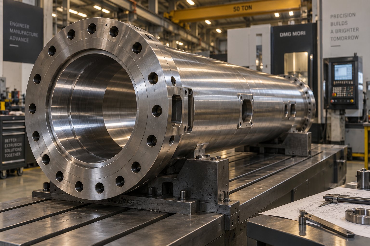
Inside an Extruder Barrel Manufacturer: From Raw Steel to Replacement
Oct 28, 2026
Learn how an extruder barrel manufacturer turns raw steel into precision barrels — covering materials, bimetallic vs nitrided linings, wear modes, and supplier evaluation.
Read Article
HDPE Pipe Extrusion Machine Decoded: From Resin to Finished Pipe
Oct 28, 2026
Learn how an HDPE pipe extrusion machine works — from extruder types and die heads to downstream equipment, specs by diameter class, and a buyer's checklist.
Read Article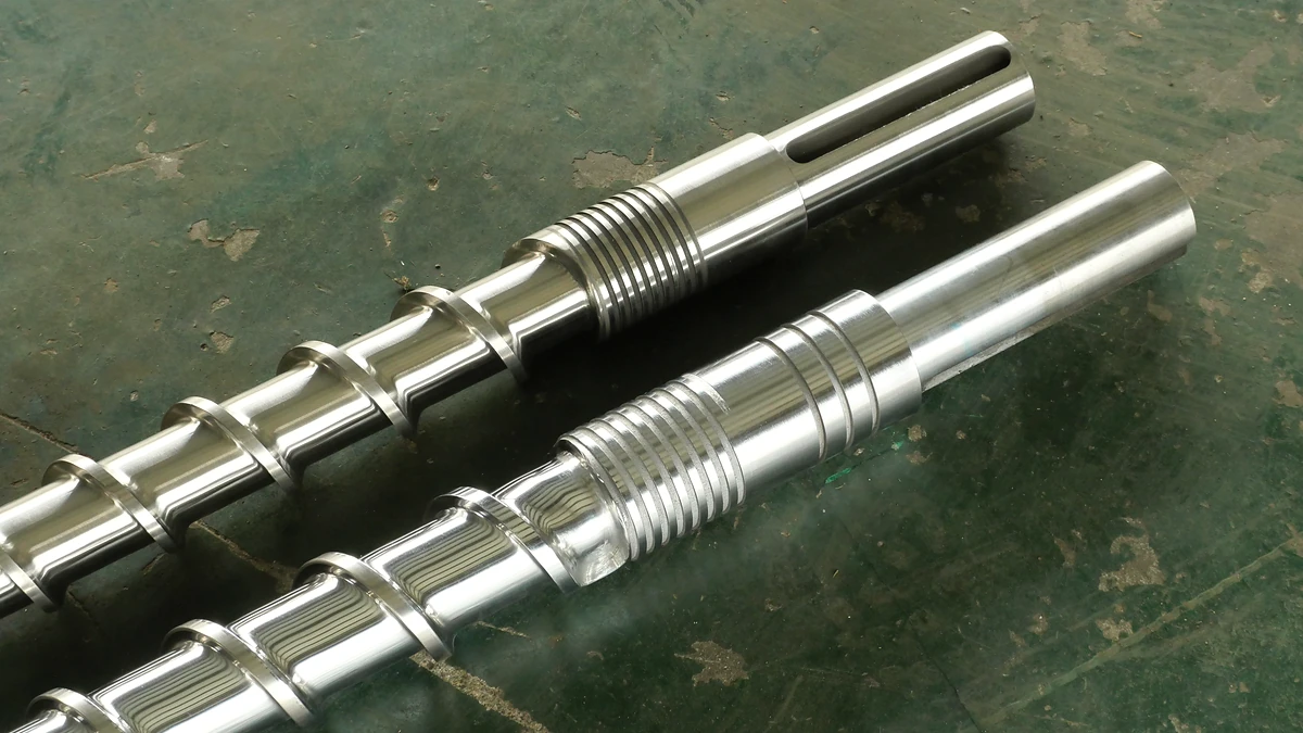
How The Wrong Extruder Screw Barrel For PP Ruins Your Melt
Oct 27, 2026
Learn why PP extrusion needs a purpose-built extruder screw barrel for PP — covering geometry, metallurgy, mixing elements, temperature profiles, and troubleshooting.
Read ArticleLooking for something else?
Search by material, symptom or product and jump straight to the relevant page.
These are navigation suggestions based on keyword matching — not a quotation, not a delivery commitment, and not a substitute for engineering review. Final specification is confirmed by our engineers against your drawings and processed material.
Need help with screw barrel selection?
Share your machine model, processed material and application. Our team can help with pricing and technical support.