

What Is an HDPE Pipe Extrusion Machine and Why It Matters
Imagine a system that takes tiny plastic pellets at one end and delivers fully formed, pressure-rated pipes at the other — continuously, around the clock. That is exactly what an HDPE pipe extrusion machine does, and it is far more than a single piece of equipment.
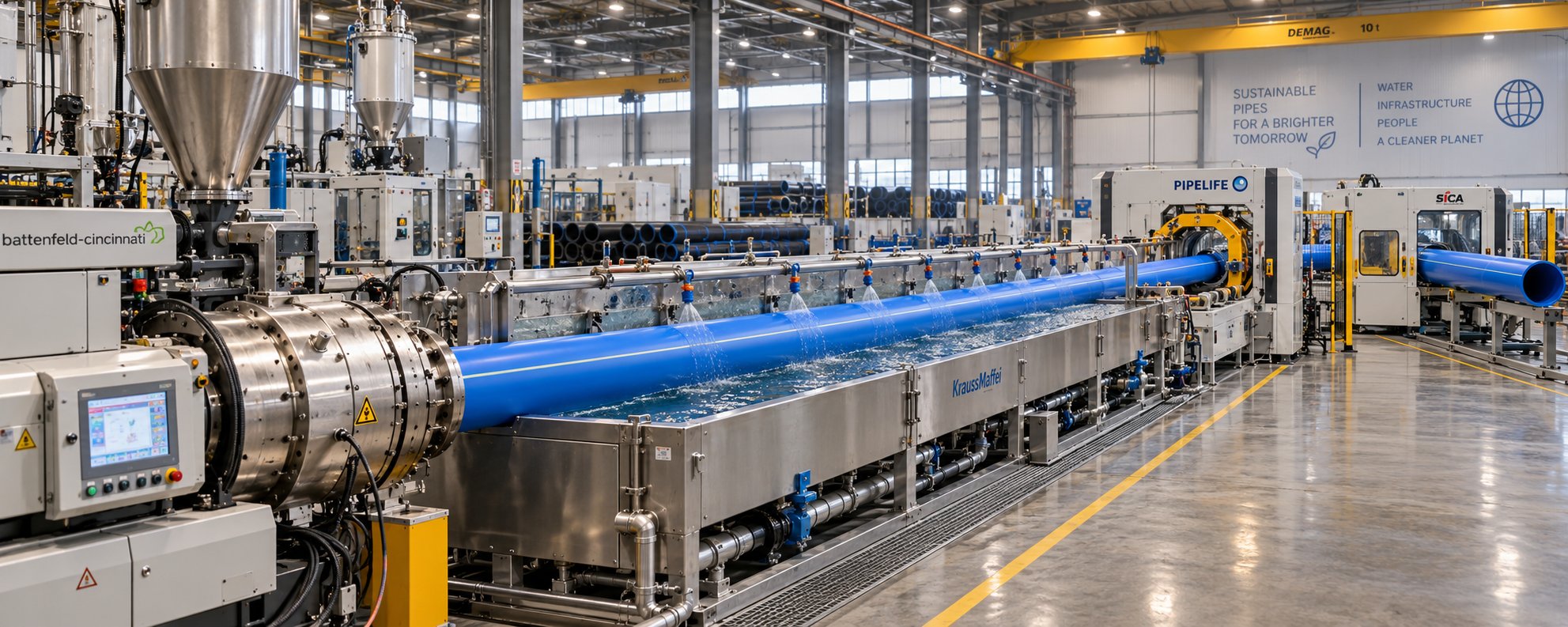
An HDPE pipe extrusion machine is an integrated production system — comprising an extruder, die head, vacuum calibration tank, cooling section, haul-off unit, and cutting station — that converts raw high-density polyethylene resin pellets into continuous, dimensionally precise hollow pipes.
Defining the HDPE Pipe Extrusion Machine
The term "machine" can be misleading here. In practice, you're looking at an entire production line where each station performs a distinct role: melting and homogenizing the resin, shaping the molten polymer through a die, locking in the pipe's outer diameter under vacuum, progressively cooling the wall, pulling the solidifying pipe at a controlled speed, and cutting it to length. Every station depends on the one before it and directly influences the one after it.
This systems-level perspective is what separates HDPE pipe extruders from other plastic pipe extrusion equipment. While PVC lines often rely on twin-screw extruders due to PVC's thermal sensitivity, HDPE lines typically center on a robust single-screw extruder optimized for polyethylene's higher melt temperatures and broader processing window. The screw geometry, barrel temperature profiles, and die head flow-channel design are all purpose-built for polyethylene extrusion, making the equipment distinct even from lines designed for PP or PEX pipes.
Why HDPE Pipe Demand Drives Equipment Innovation
Understanding the machine matters because the market it serves is enormous — and expanding. The global HDPE pipes market was valued at USD 24.44 billion in 2025 and is projected to reach USD 37.93 billion by 2034, growing at a CAGR of 5.0%. Municipal water supply and sewerage networks account for the largest share of demand, but agricultural irrigation, gas distribution, telecom ducting, and industrial fluid transport all contribute to steady growth worldwide.
Asia Pacific alone represented nearly 47% of global HDPE pipe consumption in 2025, driven by large-scale urbanization and infrastructure spending across China and India. In North America, aging pipeline rehabilitation and stormwater management projects keep demand strong. For engineers, plant managers, and procurement professionals evaluating new capacity or line upgrades, this growth translates into a practical question: which equipment configuration delivers the quality, throughput, and reliability your specific application demands?
This article answers that question from the machine side — not as a process overview or a product catalog, but as a detailed equipment resource. You'll walk through the complete anatomy of an HDPE extrusion line, compare extruder types, examine die head designs, explore downstream precision equipment, and finish with maintenance strategies and a buyer's evaluation checklist. The goal is to give you the technical depth needed to make informed decisions about HDPE extrusions and the production systems behind them.
Every high-performing pipe starts inside the extruder barrel — and that is exactly where the next section picks up, tracing the journey of a resin pellet from the hopper all the way to the stacking table.
Complete Anatomy of an HDPE Pipe Extrusion Line
A plastic pipe extrusion machine line looks deceptively simple from a distance — a long row of equipment stretching across the factory floor with resin going in one end and finished pipe coming out the other. Step closer, though, and you'll find nine distinct stations, each performing a precise task that the next station absolutely depends on. Treating this pipe extrusion line as a chain of isolated machines is a recipe for quality problems. The real advantage comes from understanding it as a single, unified system.
From Resin Hopper to Finished Pipe
Picture a resin pellet dropping into the hopper. Here is every station it passes through — and what happens at each stop — before it becomes part of a finished HDPE pipe.
Raw material handling and drying. HDPE pellets are stored in silos or bulk bags and conveyed to the extruder hopper via vacuum loaders. While HDPE is less moisture-sensitive than nylon or PET, consistent material temperature and clean handling conditions still matter. A gravimetric dosing system weighs material in real time, ensuring the extruder receives a constant, measured feed rate rather than a variable volumetric flow.
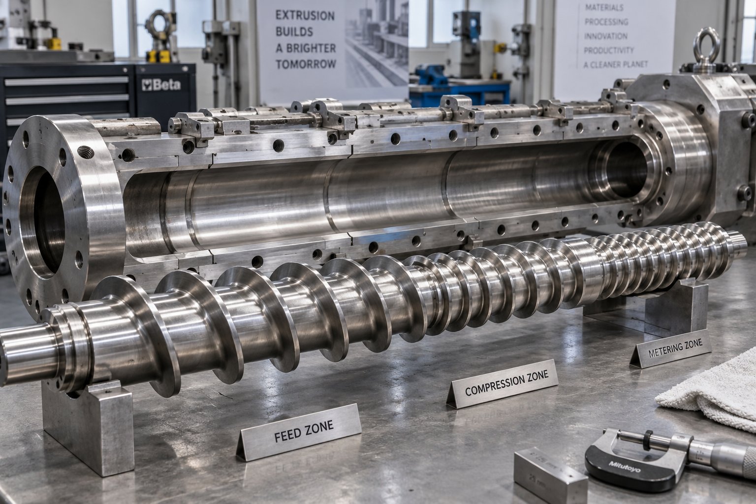
Extruder. This is the heart of the entire line. Inside a heated barrel, a rotating screw conveys, compresses, and melts the pellets across three functional zones — the feed zone, the compression zone, and the metering zone. The screw's length-to-diameter (L/D) ratio, typically 30:1 to 36:1 for HDPE, along with its compression ratio and flight depth, determines melt quality and throughput stability.
Screen changer and melt pump. Molten polymer passes through a screen pack supported by a breaker plate. This assembly filters contaminants — unmelted gels, metal particles, degraded material — and builds the back pressure needed for uniform melt homogeneity. A melt pump downstream further stabilizes pressure fluctuations, delivering a steady volumetric flow to the die.
Die head and mandrel assembly. The melt enters a die head where it is distributed evenly around a central mandrel and shaped into a hollow tube. Spiral mandrel dies are the most common design for polyethylene extrusion because their helical channels eliminate weld lines and produce excellent wall-thickness uniformity.
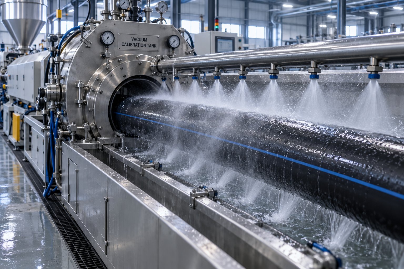
Vacuum calibration tank. The soft, hot pipe exits the die and immediately enters a vacuum calibration tank. Negative pressure inside the tank draws the pipe outward against a precision sizing sleeve, locking in the outer diameter and initial wall dimensions. Water jets simultaneously begin cooling the outer surface.
Spray cooling tanks. One or more additional cooling tanks progressively bring the pipe temperature down. Water temperature — commonly held between 15 and 20 degrees Celsius — and tank length directly influence crystallinity development and residual stress levels within the pipe wall.
Haul-off unit. A caterpillar-type or belt-type haul-off grips the solidified pipe and pulls it through the downstream section at a constant speed. This pulling speed must stay precisely synchronized with the extruder's output rate.
Cutting station. Planetary cutters rotate around the pipe to deliver chipless, burr-free cuts ideal for small and medium diameters. For large, thick-walled pipes, saw cutters provide the torque and blade rigidity needed for clean separation.
Stacking or coiling. Rigid pipes in larger diameters are lifted onto stacking racks or conveyor systems. Smaller, flexible pipes are wound onto coils by automatic winding machines for easier transport and installation.
| Component | Primary Function | Key Specification to Watch |
|---|---|---|
| Raw Material Handling & Drying | Stores, conveys, and doses resin pellets to the extruder | Dosing accuracy (gravimetric vs. volumetric) |
| Single-Screw Extruder | Melts, homogenizes, and pressurizes HDPE resin | Screw diameter, L/D ratio (30:1–36:1), motor power |
| Screen Changer & Melt Pump | Filters contaminants and stabilizes melt pressure | Screen mesh size, pump displacement volume |
| Die Head & Mandrel Assembly | Shapes molten polymer into a hollow pipe profile | Die type (spiral mandrel), gap adjustability |
| Vacuum Calibration Tank | Locks outer diameter via negative pressure and sizing sleeve | Vacuum pressure range (0.02–0.08 MPa typical) |
| Spray Cooling Tanks | Progressively solidifies pipe wall | Water temperature (15–20 °C), total tank length |
| Haul-Off Unit | Pulls pipe at constant, synchronized speed | Pulling force capacity, speed range, grip type |
| Cutting Station | Cuts pipe to specified lengths | Cutter type (planetary vs. saw), max wall thickness |
| Stacking / Coiling Unit | Organizes finished pipes for storage or shipping | Max pipe diameter for coiling, stacker capacity |
How Components Interact as a Unified System
Here is where a systems-thinking approach pays off. Each station in the HDPE extrusion line does not operate in isolation — it creates conditions that the next station must accommodate, and any mismatch ripples downstream.
Consider the most critical relationship: extruder output rate versus haul-off speed. If the haul-off pulls faster than the extruder delivers melt, the pipe wall stretches and thins beyond tolerance. Pull too slowly, and the pipe wall thickens while the line backs up, potentially causing sag or ovality before the calibration tank can compensate. Modern lines use closed-loop PLC control to keep these two speeds locked in ratio, but operators still need to understand the relationship when changing pipe sizes or resin grades.
Vacuum calibration pressure presents another interdependency. If vacuum is too low, the pipe doesn't contact the sizing sleeve firmly, resulting in undersized outer diameter and poor roundness. Too much vacuum, and the outer surface freezes against the sleeve while the inner wall is still molten — creating uneven residual stress that can lead to warpage after the pipe cools completely. The cooling water temperature and tank length downstream must then match the line speed so the pipe reaches a stable, uniform temperature before the haul-off grips it.
Even the screen changer plays a system role. As the screen pack accumulates contaminants, back pressure rises gradually. This shifts the extruder's operating point, altering melt temperature and output unless the control system compensates. Automatic screen changers that swap screens without interrupting flow help maintain stability, but the operator still needs to monitor pressure trends.
The takeaway? Optimizing a single station in isolation often shifts problems elsewhere. The best-run lines treat the entire pipe extrusion line as one process with many control points.
Optional Precision Add-Ons
Beyond the core stations, several upgrades can tighten quality control and reduce material waste on an HDPE extrusion line:
- Gravimetric dosing systems — Rather than feeding pellets by volume, these units measure by weight. As Rollepaal notes, saving just 1–2% of raw material through precise gravimetric control can deliver a payback period of less than one year, with additional savings from reduced reject rates.
- Ultrasonic wall-thickness measurement — Sensors mounted after the calibration tank measure wall thickness at multiple points around the circumference in real time. Feedback loops can automatically adjust die centering or haul-off speed to correct deviations before they produce out-of-spec pipe.
- Inline printing and marking — Inkjet or hot-stamp printers apply product identification — pipe size, material grade, manufacturer, production date, and meter markings — directly on the pipe surface as it moves through the line, eliminating a separate labeling step.
These add-ons are not luxuries on high-volume lines. They directly reduce scrap, speed up quality audits, and provide traceability data that many municipal and industrial buyers now require.
With the full layout of the line mapped out, one station deserves a much closer look: the extruder itself. The choice between a single-screw and a twin-screw configuration shapes everything from capital cost to the types of resin you can process — and the differences are more nuanced than most summaries suggest.
Single-Screw vs Twin-Screw Extruders for HDPE Pipe
Ask any seasoned plant engineer which extruder type runs their HDPE pipe line, and the answer is almost always the same: a single-screw machine. That dominance is not accidental — it reflects the specific way HDPE resin behaves during melting and conveying. Still, twin-screw configurations earn their place in certain production scenarios. Knowing exactly where each architecture excels — and where it falls short — prevents costly mismatches between your plastic pipe extruder and your production goals.
| Feature | Single-Screw Extruder | Twin-Screw Extruder |
|---|---|---|
| Throughput Range | Moderate to very high (scalable with screw diameter up to 150 mm+) | Moderate; excels at compounding rather than pure pipe output |
| Energy Efficiency | High for polyolefin pellets — drag-flow conveying aligns well with HDPE | Higher energy per kg due to intensive mixing action |
| Maintenance Complexity | Lower — fewer moving parts, straightforward screw and barrel replacement | Higher — two screws, more complex gearbox, tighter tolerances |
| Material Flexibility | Best for virgin pelletized resins (HDPE, PP, PE-RT) | Handles powders, high-filler blends, and mixed regrind streams |
| Capital Cost | Lower upfront investment for equivalent output capacity | Significantly higher, especially co-rotating parallel designs |
| Best-Use Scenarios | Standard HDPE water, gas, and sewer pipe production | Compounding, recycled-content processing, multilayer adhesive layers |
Single-Screw Extruders in HDPE Pipe Production
Single-screw extruders are the industry workhorse for HDPE pipe for a straightforward reason: HDPE arrives as uniform, pre-pelletized granules that respond exceptionally well to friction-based drag-flow conveying. The resin's consistent granule size and relatively high coefficient of friction against the barrel wall mean a well-designed single screw can move, compress, and melt material efficiently without the elaborate intermeshing action a twin-screw system provides.
Three screw geometry parameters determine melt quality and throughput stability in a single-screw HDPE extruder:
- L/D ratio (length-to-diameter). Most HDPE pipe screws fall between 30:1 and 36:1. As extrusion specialist Allan Griff explains, more length can mean more output when heating, melting, or mixing are the limiting factors. Longer screws give the polymer additional residence time for complete melting and homogenization — critical for thick-walled pressure pipes.
- Compression ratio. This ratio of the feed zone channel depth to the metering zone channel depth typically falls between 2.5:1 and 3.5:1 for HDPE. It controls how aggressively air is expelled from the pellet bed and how much shear heat is generated. A ratio that is too low leaves unmelted particles; too high, and excessive shear heat can degrade the polymer.
- Flight depth. The metering zone flight depth sets the shear rate and pumping capacity. Shallower flights increase shear but reduce throughput per revolution, while deeper flights improve output at the expense of mixing quality. Many modern HDPE pipe screws use barrier-flight designs that separate the melt from the remaining pellets, boosting melting efficiency per rpm without overheating the polymer.
Beyond geometry, flight-to-barrel clearance on a new screw typically sits between 0.125 and 0.25 mm. As this gap widens from wear, material leaks backward over the flights — a phenomenon called leakage flow. The result? You'll notice the screw must spin faster to maintain the same output, generating more heat and gradually degrading melt consistency and pipe wall-thickness control.
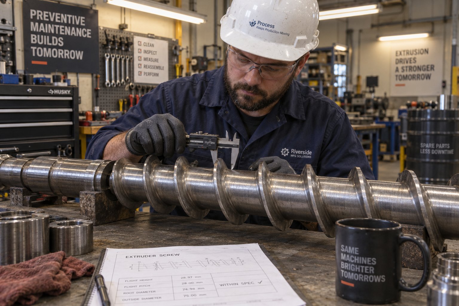
This makes the screw and barrel assembly the single most critical wear component on the entire plastic pipe extrusion line. Barrel liners are typically bimetallic alloy sleeves designed to resist abrasion, while screw flight tips receive hard-facing alloys to delay wear. Even so, every production hour adds incremental wear. Monitoring the clearance gap through regular dimensional audits — and replacing barrels before degradation reaches the point of unstable output — is essential for maintaining pipe quality and avoiding unplanned downtime.
From a procurement standpoint, having a reliable source for custom and replacement single screw barrels shortens maintenance windows considerably. Specialist manufacturers like NANHAIYA offer precision-machined, application-matched barrel assemblies for pipe extrusion lines, helping plant managers keep spare inventory on hand rather than waiting weeks for a factory-original part. Since barrel wear directly impacts melt consistency and throughput stability, a dependable barrel supplier is a practical investment in production uptime — not just a spare parts transaction.
When Twin-Screw Extruders Make Sense
Does a twin-screw hdpe extruder ever belong on a pipe production line? Absolutely — under specific conditions. Twin-screw configurations shine when the material itself demands intensive mixing that a single screw cannot deliver. Typical scenarios include:
- High percentages of recycled content. Post-consumer HDPE regrind varies widely in melt flow index, density, and contamination levels. A co-rotating twin-screw extruder's intermeshing, self-wiping screw elements deliver the dispersive and distributive mixing needed to homogenize inconsistent flake or pellet blends into a uniform melt — something a standard single screw struggles to achieve when regrind exceeds roughly 30% of the feed.
- Heavily filled compounds. Mineral fillers like calcium carbonate or titanium dioxide at high loading levels need the enhanced conveying and compounding action twin screws provide. Abrasive fillers also accelerate wear, demanding bimetallic barrel liners and hardened screw elements — a maintenance consideration that increases operating cost but is unavoidable for these recipes.
- Multilayer co-extrusion adhesive layers. In multilayer pipe lines, the thin adhesive or tie layer between dissimilar materials often requires a small twin-screw unit for precise, low-volume dosing and thorough melt blending of specialty resins.
- Dry-blend PVC formulations. While outside the HDPE scope of this article, it's worth noting that twin screws are the default choice for PVC pipe lines because PVC arrives as a heat-sensitive powder blend rather than stable pellets — a processing reality that single-screw friction-based conveying handles poorly.
For standard HDPE water, gas, and sewer pipe production using virgin PE80 or PE100 pellets, the economics and simplicity of a single-screw plastic pipe extrusion line remain hard to beat. The twin-screw option enters the picture only when material complexity — not pipe geometry — demands it.
Whichever extruder type feeds the line, the melt still must be shaped into a precise hollow profile. That job falls to the die head — and the differences between die designs influence pipe quality in ways that deserve their own close examination.
Die Head Types and Their Impact on HDPE Pipe Quality
The extruder does the heavy lifting of melting and pressurizing the resin, but it is the die head that ultimately decides whether you produce a precision-grade pressure pipe or a reject destined for regrind. Think of it this way: the extruder delivers a stream of homogeneous melt, and the die head must distribute that stream into a perfectly uniform hollow cylinder — all while the melt is moving continuously at high pressure. Even a small imbalance in flow distribution inside the die shows up immediately as a wall-thickness deviation in the finished pipe. That is why understanding the pipe extrusion process at the die level is essential for anyone evaluating or operating an HDPE pipe extrusion machine.
Three primary die-related elements shape the quality of every meter of pipe that leaves the line: the spiral mandrel die, the basket die, and the upstream screen-pack and breaker-plate assembly that conditions the melt before it ever reaches the die. Each plays a distinct role, and the choice between them depends on pipe diameter, production speed, and quality requirements.
Spiral Mandrel Dies and Why They Dominate
If you examine most HDPE pipe extrusion lines producing pipes from 16 mm up to roughly 800 mm, you'll find a spiral mandrel die at the center of the forming station. Its dominance is well earned.
Inside a spiral mandrel die, the incoming melt stream splits into multiple channels that wrap helically around a central mandrel. As these spiral channels progress toward the die exit, their depth gradually decreases while the gap between the mandrel and the outer die body increases. The result is an elegant overlap: melt from each channel spreads laterally and merges with the flow from adjacent channels, creating a seamless, homogeneous tubular melt curtain by the time it reaches the annular die lip.
Why does this matter? Because the spiral overlap geometry effectively eliminates weld lines — those visible or structural weak points that form wherever two separate melt fronts meet head-on. In older spider-type dies commonly used for PVC, the support legs that hold the mandrel in place physically split the melt flow, creating distinct weld lines that can reduce the pipe's burst pressure. Spiral mandrel dies avoid this problem entirely, which is a critical advantage for HDPE pressure pipes rated to PE80 or PE100 standards.
The even melt distribution also delivers tight wall-thickness tolerances. As Rollepaal's optimization guide highlights, die design is critical for pipe quality aspects like wall distribution and surface finish — and spiral mandrel dies consistently achieve the circumferential uniformity that municipal water and gas pipe standards demand. When the melt exits the die with balanced flow in every direction, the downstream vacuum calibration tank has a much easier job locking in dimensional accuracy.
Basket Dies and Large-Diameter Applications
Spiral mandrel dies work beautifully across most standard pipe sizes, but when diameters push above 800 mm, the physical size of the spiral channel system becomes impractical. The mandrel grows enormous, flow-path lengths increase dramatically, and residence time inside the die rises to a point where thermal degradation of HDPE becomes a genuine risk.
This is where basket dies — sometimes called screen-type or plate-type distributor dies — enter the picture. Instead of spiral channels, basket dies use a series of perforated plates or rings to distribute the melt radially outward from a central entry point. The melt is forced through progressively finer distribution screens, spreading it around the full circumference before it reaches the annular exit gap.
The trade-offs are real. Basket dies are simpler to manufacture at very large scales and handle the massive melt volumes required for extra-large-diameter pipes. However, they are more prone to subtle flow imbalances than spiral designs, meaning operators need to pay closer attention to temperature uniformity and die-gap adjustment. Surface finish can also be slightly less consistent compared to the smooth overlap pattern of a well-designed spiral mandrel. For manufacturers producing pipes in the 800 mm to 1600 mm range for industrial outfall lines or marine applications, basket dies remain the practical engineering choice — but they demand experienced process setup.
Die Gap Adjustment and Its Effect on Pipe Quality
Regardless of whether the line uses a spiral mandrel or basket die, one hands-on adjustment determines day-to-day pipe quality more than almost any other: die gap concentricity.
Every pipe die head is equipped with a set of centering bolts — typically four, arranged at 90-degree intervals — that allow operators to shift the position of the inner mandrel relative to the outer die ring. Adjusting these bolts changes the annular gap through which the melt exits. A wider gap on one side means more material flows there, producing a thicker wall. A narrower gap restricts flow and produces a thinner wall.
As detailed in a technical analysis by Wanplas, the recommended approach is small-amplitude, incremental fine-tuning — each adjustment limited to roughly 0.1 mm of gap change — followed by 3 to 5 minutes of trial extrusion and cross-sectional wall-thickness measurement. Overcorrecting in a single move frequently causes reverse eccentricity, forcing operators into a frustrating back-and-forth cycle.
Temperature also plays a hidden role. Uneven die temperature distribution causes the melt to flow faster through hotter zones and slower through cooler zones, mimicking the effect of a mechanical gap imbalance. Modern die heads feature multi-zone independent heater bands so operators can fine-tune thermal uniformity alongside mechanical centering.
When die alignment and temperature are both off, the defects compound. Here are the most common die-related pipe quality issues and what causes them:
- Uneven wall thickness (eccentricity): Misaligned centering bolts creating an asymmetric die gap, or localized die temperature differences causing faster flow on one side. This is the single most frequent die-related defect in HDPE pipe production.
- Weld lines: Visible seams or structurally weak zones where separate melt streams converge without fully bonding. Most commonly associated with spider dies, but can appear in poorly designed or damaged spiral dies where channel overlap has degraded.
- Melt fracture: A rough, shark-skin-like surface texture caused by excessive shear stress at the die lip. This typically results from a die gap that is too narrow for the given throughput rate, or from processing a resin at too low a temperature where its melt viscosity exceeds the die's flow capacity.
- Surface roughness and drag marks: Caused by carbon deposits, scratches, or burrs on the die land surface that drag across the melt as it exits. Regular cleaning and polishing of the die's inner surfaces — especially after extended production runs — prevents this defect from developing gradually.
Understanding how is HDPE manufactured at the die level gives engineers and operators a powerful diagnostic advantage. When a pipe defect appears, the die head is often the first place to investigate — and knowing whether the root cause is mechanical alignment, thermal imbalance, or surface contamination saves hours of blind troubleshooting.
Of course, even a perfectly tuned die head only creates a hot, soft tube of polymer. Turning that fragile extrudate into a rigid, dimensionally stable pipe depends entirely on what happens next — in the vacuum calibration tank and the cooling stations that follow.
Downstream Equipment That Defines Pipe Precision
A perfectly homogenized melt and a flawlessly centered die gap mean nothing if the soft, hot tube emerging from the die head is not immediately stabilized, cooled, pulled, and cut with equal precision. Downstream equipment rarely gets the attention it deserves — most equipment discussions focus almost exclusively on the extruder — yet it is these stations that ultimately determine whether a PE pipe extrusion line produces pipes that pass dimensional inspection or generates scrap by the meter.
Think of it this way: the extruder and die head create the pipe's potential quality. The downstream section locks that quality in — or destroys it. Every percentage point of ovality, every tenth of a millimeter of wall-thickness deviation, and every surface imperfection that appears on the finished product can usually be traced back to a downstream setting that was slightly off.
Vacuum Calibration and Spray Cooling Tanks
The moment the molten HDPE tube exits the die lip, gravity and its own weight begin pulling it out of shape. Without immediate intervention, the soft extrudate would sag, deform, and lose any resemblance to a round pipe within seconds. The vacuum calibration tank provides that intervention.
Inside the tank, a precision-machined sizing sleeve — typically chrome-plated stainless steel with a tolerance within plus or minus 0.02 mm — establishes the pipe's outer diameter. A controlled negative pressure environment, typically ranging from 0.02 to 0.06 MPa, creates a differential that pushes the hot pipe outward against the sleeve's inner surface. Simultaneously, high-velocity water spray manifolds operating at 0.2 to 0.35 MPa spray pressure deliver turbulent water contact around the pipe's circumference, rapidly freezing the outer skin in place.
Why does this two-part action — vacuum plus cooling — matter so much? Because HDPE is a semi-crystalline polymer. Unlike amorphous plastics that simply harden as they cool, HDPE undergoes a crystallization process that is highly sensitive to cooling rate. Cool the outer wall too quickly with excessively cold water, and you create a frozen skin while the inner wall remains molten — a recipe for locked-in residual stress that can cause warpage or long-term creep failures. Cool too slowly, and the pipe loses its round shape before the material solidifies enough to hold form.
Spray cooling tanks positioned after the vacuum calibration tank continue the solidification process progressively. Water temperature in these tanks is commonly held between 15 and 20 degrees Celsius, and the total tank length must be scaled to match line speed. Faster production rates demand longer cooling sections so the pipe reaches a stable, uniform temperature before it contacts the haul-off grips. In a well-configured hdpe plant, you might find two, three, or even more cooling tanks in series for large-diameter, thick-walled pipes where the thermal mass is substantial.
A subtle but important detail: the water temperature in the first calibration tank is often set slightly warmer than in subsequent spray tanks. This staged approach prevents thermal shock on the outer surface and encourages a more gradual crystallization front moving inward through the pipe wall — ultimately producing a pipe with more balanced mechanical properties and lower residual stress.
Haul-Off Units and Speed Synchronization
Once the pipe exits the cooling section, it needs to keep moving at a constant, precisely controlled speed. That job falls to the haul-off unit — and getting it right is more critical than it might sound.
Two main designs dominate. Caterpillar-type haul-offs use two opposing tracks of rubber-padded blocks — resembling a tank's treads — that grip the pipe from top and bottom and pull it forward. The upper caterpillar typically features a pneumatic flexible clamping mechanism that adapts contact pressure automatically based on pipe diameter and wall thickness, preventing crush marks on softer pipes while maintaining enough grip to avoid slippage. The lower caterpillar can be electrically adjusted to the required position for each pipe specification. Belt-type haul-offs use continuous rubber belts instead of individual pads, offering a longer contact area that distributes pulling force more evenly — an advantage for very large or thin-walled pipes that are sensitive to localized pressure.
Modern haul-off units integrate AC servo drives that synchronize pulling speed with extruder output in real time. Even small mismatches between these two speeds create visible quality problems. Pull too fast, and the pipe wall stretches and thins beyond tolerance — a defect that may not be obvious visually but shows up immediately during ultrasonic wall-thickness measurement. Pull too slowly, and material accumulates between the die and the calibration tank, causing sag and ovality before the vacuum can compensate. On advanced PE pipe extrusion lines, the haul-off and extruder share a closed-loop speed ratio controlled by the line's central PLC, automatically compensating for minor fluctuations in melt pressure or cooling conditions.
Versatility also matters for plants running multiple pipe sizes. Some haul-off units accommodate diameters ranging from as small as 5 mm to as large as 2800 mm, with configurations offering 2, 4, 6, 8, or even up to 16 caterpillar tracks for extra-large pipes. This adaptability reduces changeover time when switching between product sizes — a meaningful productivity factor in plants that produce a wide range of pipe diameters on the same pe pipe extrusion machine.
Cutting Systems and End-of-Line Handling
The pipe is cooled, dimensionally stable, and moving steadily — and it needs to be separated into precise lengths without damaging what the rest of the line worked so hard to produce. The choice of cutting system depends primarily on pipe diameter, wall thickness, and material rigidity.
Planetary cutters are the preferred choice for small to medium-diameter HDPE pipes. A circular cutting wheel orbits around the pipe's circumference on a rotating ring, gradually pressing inward and splitting the pipe apart cleanly — much like a plumber's hand-held pipe cutter, but automated and traveling with the moving pipe on a servo-controlled table. The key advantage is that planetary cutters are chipless: they displace material rather than removing it, producing zero dust or shavings and leaving square, distortion-free ends. For pipes feeding into automated assembly or socket-fusion joining processes, this particle-free cut eliminates contamination risks.
Saw cutters become necessary for large-diameter, thick-walled pipes where the cutting wheel of a planetary cutter simply cannot generate enough penetration force. Traveling saw cutters use a circular blade mounted on a servo-driven table that momentarily clamps to the moving pipe, matches its speed, and makes the cut while both travel together. The trade-off is that saw blades remove a narrow swath of material, generating plastic "sawdust" that requires a vacuum collection system. Cut-length precision on modern servo-controlled saw tables is excellent, but operators must monitor blade condition closely — a dull blade introduces burrs and can create cut-length variation as the blade drags through the material.
After cutting, automatic stacking systems receive rigid pipes and arrange them in bundles on tilting racks or conveyor cradles, ready for strapping and transport. For smaller-diameter pipes — typically under 110 mm — automatic coiling machines wind the pipe onto spools or into coils, dramatically simplifying logistics for plumbing and telecom ducting applications where continuous, jointless pipe lengths are preferred on the job site.
| Downstream Unit | Function | Typical Adjustment Parameters |
|---|---|---|
| Vacuum Calibration Tank | Locks outer diameter by drawing the hot extrudate against a sizing sleeve using negative pressure | Vacuum level (0.02–0.06 MPa), water spray pressure (0.2–0.35 MPa), water temperature (15–20 °C), sizing sleeve diameter |
| Spray Cooling Tanks | Progressively solidifies the pipe wall through controlled water spray contact | Water temperature per tank, total tank length relative to line speed, spray nozzle arrangement and flow rate |
| Haul-Off Unit (Caterpillar / Belt) | Pulls the solidified pipe at a constant speed synchronized with extruder output | Pulling speed (matched to extruder output ratio), clamping pressure, caterpillar pad or belt contact length, servo drive response time |
| Planetary Cutter | Chipless, orbital cutting for small and medium-diameter pipes | Cutting wheel feed rate, travel table speed (matched to line speed), wheel sharpness and replacement interval |
| Saw Cutter | Circular-blade cutting for large-diameter, thick-walled pipes | Blade RPM, travel table clamp pressure, blade type and tooth geometry, vacuum collection airflow |
| Automatic Stacker | Arranges rigid pipe lengths into organized bundles for storage and shipping | Stacking height, cradle spacing based on pipe diameter, tilt angle for gravity feed |
| Pipe Coiler / Winder | Winds flexible, smaller-diameter pipes onto spools or into coils | Coil diameter, winding tension, maximum pipe diameter for coiling (typically under 110 mm) |
Every parameter listed in that table interacts with the upstream stations. Raise the line speed at the extruder, and the cooling tanks may no longer provide enough residence time. Change the pipe diameter, and the haul-off clamping pressure, vacuum level, sizing sleeve, and cutter setup all need recalibration. This cascading interdependence is exactly why experienced operators treat the downstream section not as an afterthought, but as half of the production equation.
Dialing in these mechanical settings, however, is only part of the picture. The HDPE resin grade itself — its density, melt flow rate, and molecular weight distribution — dictates which temperature profiles, screw speeds, and vacuum pressures you should target in the first place. Getting that resin-to-machine match right, and leveraging modern automation to hold it steady, is where the next layer of production intelligence comes in.
Process Parameters, Resin Selection, and Smart Controls
Here is something most equipment guides overlook entirely: the same HDPE pipe extrusion machine, with the same screw, the same die head, and the same downstream configuration, will produce dramatically different results depending on which resin you feed it — and how you adjust the process to match. A PE100 pressure pipe grade and a PE80 distribution-class resin may look identical sitting in a bulk bag, but they behave very differently inside the barrel. Ignoring that difference leads to defects, wasted energy, and frustrated operators chasing problems that no mechanical adjustment can fix.
The connection between resin properties and machine parameters is the bridge between raw material science and extruded pipe manufacturing in practice. Modern automation systems make holding that bridge steady far easier than it was a decade ago — but only if the operator understands what the controls should be targeting in the first place.
Matching Resin Grade to Machine Parameters
HDPE resins are not a single material. They span a range of densities, molecular weights, and flow characteristics, and each variation demands its own processing window on the hdpe extrusion line. Two resin classifications dominate pipe production worldwide: PE80 and PE100. The numbers refer to the material's Minimum Required Strength — 8.0 MPa and 10.0 MPa respectively — and the differences in their molecular architecture translate directly into different barrel temperature profiles, screw speeds, and die pressures.
PE100 grades are the standard for high-pressure water and gas transmission pipes rated to SDR 7 through SDR 17. These resins have higher molecular weight and lower melt flow index (MFI) values — typically 0.20 to 0.40 g/10 min at 190 degrees Celsius and 2.16 kg load. That lower MFI means the melt is thicker and more viscous, requiring higher temperatures and greater back pressure to achieve uniform flow through the die. A typical PE100 barrel profile runs from 170-190 degrees Celsius in the feed zone, stepping up through 190-210 degrees in the compression zone, and reaching 210-230 degrees in the metering zone. Die temperatures climb further to 220-235 degrees at the lip.
PE80 grades, used for lower-pressure water distribution and non-pressure drainage applications, have higher MFI values — generally 0.30 to 0.70 g/10 min — and lower molecular weight. The practical result? PE80 melts more easily, flows more readily, and requires approximately 10-15 degrees Celsius less heat across every zone compared to PE100. Feed zone temperatures typically start at 160-175 degrees, and the die lip runs at 205-220 degrees. Pushing PE80 through a temperature profile designed for PE100 wastes energy and risks thermal degradation, while running PE100 at PE80 temperatures produces incomplete melting and poor pipe quality.
Within the PE100 family itself, further variation exists. Crack-resistant PE100-RC grades process at slightly lower temperatures than standard PE100, while high-stiffness PE100-HD resins designed for large-diameter applications may need metering zone setpoints as high as 235 degrees Celsius. You'll find the specific processing window for any grade on the resin supplier's technical datasheet — and treating that datasheet as your starting recipe is always smarter than relying on a generic temperature chart.
Beyond temperature, MFI directly influences screw speed selection. A low-MFI PE100 resin generates more shear heat per revolution because of its higher viscosity, so screw speed must be balanced against the risk of overheating. Running the screw too fast on a PE100 grade can push the actual melt temperature 10-20 degrees above the zone setpoint through viscous dissipation alone — a hidden heat source that barrel thermocouples do not directly measure. Conversely, a higher-MFI PE80 resin tolerates faster screw speeds without the same overheating risk, which is one reason PE80 lines often achieve higher throughput rates on the same equipment.
Automation and Control Systems in Modern Lines
Imagine trying to keep all those temperature zones, screw speed ratios, vacuum pressures, and haul-off speeds in balance manually — across a line that might run 20 or more hours per day. That is precisely why modern hdpe pipe extrusion lines have moved decisively toward centralized digital control.
PLC-based control forms the backbone of virtually every current-generation pe extrusion line. Programmable logic controllers from established platforms like Siemens S7-series or Allen-Bradley ControlLogix manage every parameter on the line — zone temperatures, screw RPM, melt pump speed, vacuum levels, haul-off velocity, and cutter timing — through a single integrated logic architecture. The PLC continuously reads sensor inputs, compares them against stored setpoints, and adjusts outputs in real time. When the extruder output fluctuates slightly, the PLC can compensate by adjusting haul-off speed within milliseconds, long before a human operator would even notice the deviation.
HMI touchscreen interfaces give operators a visual window into the entire process. Rather than reading dozens of individual analog gauges, the operator sees a graphical representation of the full line with live temperature readings, motor loads, pressure values, and production speed on a single screen. More importantly, modern HMIs support recipe storage — the operator selects a saved recipe for, say, "PE100 SDR11 110mm," and the system automatically loads the corresponding temperature profile, screw speed, haul-off ratio, vacuum setting, and cutter length. This eliminates manual entry errors during product changeovers and ensures repeatable quality from shift to shift.
SCADA integration takes visibility beyond the individual line. In plants running multiple hdpe pipe extrusion lines, a Supervisory Control and Data Acquisition system aggregates data from every line into a central dashboard. Plant managers can compare output rates, energy consumption, reject percentages, and uptime across lines — identifying bottlenecks or quality trends that would be invisible when looking at a single line in isolation. Production data is logged automatically, providing the traceability records that municipal and industrial pipe buyers increasingly require.
Servo-driven extruders represent a significant step forward in both precision and efficiency. Traditional AC induction motors paired with hydraulic gearboxes respond relatively slowly to speed commands and waste energy as heat in the drive system. Servo motors, by contrast, deliver instant torque response, precise speed control across a wide RPM range, and substantially lower energy losses. On an hdpe extrusion line, this translates to tighter melt pressure control — especially during startups and product changeovers — and measurably lower electricity bills per kilogram of pipe produced.
IoT-enabled monitoring is the newest layer. Sensors embedded in critical components — motor bearings, gearbox oil, barrel heater bands, cooling water pumps — feed continuous condition data to cloud-based analytics platforms. Rather than relying on calendar-based maintenance schedules, the system identifies early warning signs of component degradation: a bearing vibration signature that shifts upward, a heater band whose resistance is drifting, a vacuum pump whose performance is declining. Predictive maintenance alerts let plant teams schedule repairs during planned downtime windows rather than reacting to unexpected failures mid-production. For multi-shift operations, this shift from reactive to predictive maintenance can recover significant annual uptime.
Energy Efficiency and Consumption Patterns
Energy cost is the second-largest operating expense on any pipe extrusion line — right behind raw material. Understanding where energy goes, and how modern technology reduces waste, directly affects your cost per meter of finished pipe.
Two systems dominate the energy budget: the extruder drive motor and the barrel heater bands. Together, they typically account for 70-80% of the entire line's electricity consumption. The drive motor converts electrical energy into mechanical torque that turns the screw, while heater bands supply the thermal energy needed to reach and maintain the target barrel temperature profile. On a large-diameter pe extrusion line with a 90 mm or larger screw, the main drive motor alone might draw 150 to 400 kW depending on throughput and resin viscosity.
Several technologies chip away at this consumption:
- Servo motors and variable-frequency drives (VFDs). Replacing constant-speed AC motors with servo-driven systems cuts energy use by 20-40% in many installations. The savings come from eliminating the energy wasted when a constant-speed motor runs at less than full load — which is most of the time, since extrusion rarely demands maximum torque continuously.
- Optimized screw designs. Barrier-flight and high-performance mixing screws convert more of the motor's mechanical energy into useful polymer melting and less into wasted frictional heat. A well-designed screw can lower specific energy consumption (kWh per kg of output) by improving melting efficiency at lower screw speeds.
- Insulating barrel jackets. Without insulation, a significant portion of the heat generated by barrel heater bands radiates into the factory environment — wasted energy that also increases cooling loads on the plant's HVAC system. Insulating barrel covers reduce radiant heat loss and can cut heater energy consumption by 20-30%, paying for themselves within months.
- Efficient cooling systems. Variable-speed water pumps that adjust flow rate based on actual cooling demand consume far less energy than constant-flow systems. Tower-cooled or chiller-recirculated water loops also recover and redistribute thermal energy rather than simply discarding it.
The cumulative impact of these improvements is substantial. A modern, well-optimized hdpe pipe extrusion line can achieve specific energy consumption below 0.25 kWh per kilogram of pipe produced, compared to 0.35 kWh/kg or more on older lines with conventional drives and no insulation. Over a year of continuous operation producing hundreds of tons of pipe, that difference translates into meaningful cost savings — and a tangible reduction in the plant's carbon footprint.
Matching resin to process, automating for consistency, and squeezing waste out of every kilowatt — these are the variables that separate a profitable line from one that merely runs. Yet all of this discussion has focused on producing a single, solid HDPE wall. What happens when the market demands pipes with multiple layers — a recycled-content core, a colored identification stripe, or a peelable protective skin? That is where the equipment conversation shifts from standard extrusion to co-extrusion, and the machine configuration changes significantly.
Single-Layer vs Multilayer Co-Extrusion Machines
Most HDPE pipes buried beneath roads and running through buildings are single-layer products — one solid wall of extruded HDPE from inside surface to outside surface. For decades, that straightforward construction has been more than adequate for water supply, drainage, and irrigation. So why are an increasing number of manufacturers investing in multilayer co-extrusion capability? The answer lies in evolving market demands: recycled-content mandates, cost optimization through material layering, and application-specific functional requirements that a single-layer wall simply cannot address on its own.
Choosing between a single-layer and multilayer hdpe pipe production line is not a matter of one being "better" — it is a matter of matching equipment complexity to your actual product portfolio and commercial strategy.
Standard Single-Layer HDPE Pipe Extrusion
The vast majority of HDPE pipes for municipal water, gas distribution, and sewerage are still produced on single-layer lines. The configuration is elegant in its simplicity: one primary extruder melts and pressurizes the resin, feeds it through a single-channel die head, and the downstream section handles calibration, cooling, haul-off, and cutting exactly as described in previous sections of this article.
This simplicity brings tangible advantages. A single-layer pe pipe production line has fewer components to maintain, fewer process variables to coordinate, and a shorter learning curve for operators. Product changeovers — switching from one pipe diameter or SDR to another — involve changing the die tooling and sizing sleeve rather than rebalancing multiple melt streams. For plants producing standard PE80 or PE100 pipe against established specifications like ISO 4427, a single-layer line delivers the quality, throughput, and reliability the market requires at the lowest capital entry point.
From a process control standpoint, you are managing one melt temperature profile, one screw speed, one output rate, and one die pressure. Every control loop on the line governs a single material stream, which means troubleshooting is more straightforward and root-cause analysis is faster when defects appear. For many manufacturers — especially those entering the HDPE pipe market for the first time — this operational simplicity translates directly into faster ramp-up, lower scrap rates during commissioning, and more predictable production economics.
Multilayer Co-Extrusion Configurations
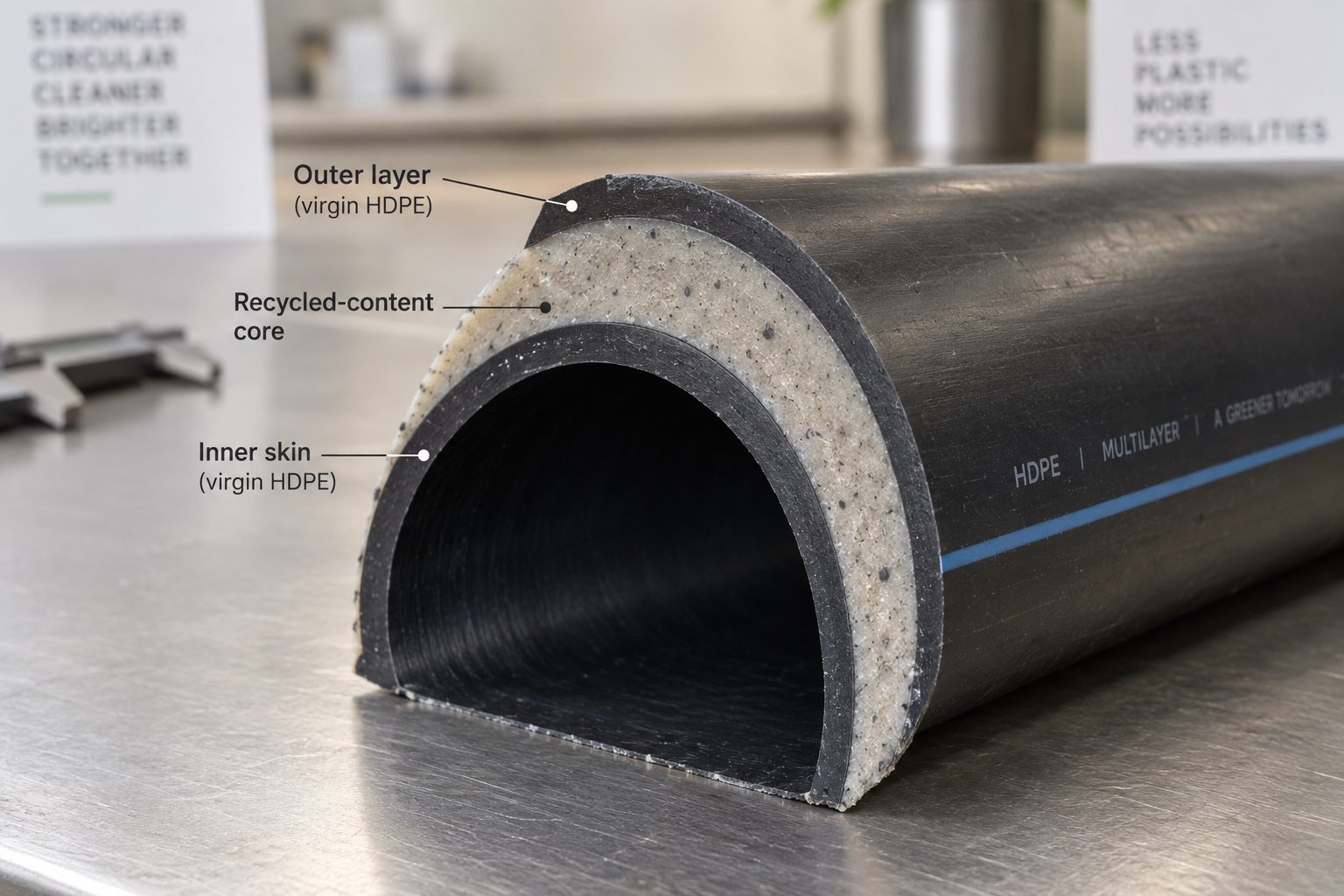
A multilayer line takes the same fundamental extrusion process and adds one or more secondary extruders — typically smaller single-screw units — that each deliver a separate melt stream into a specially designed multi-channel co-extrusion die. Inside this die, the individual streams are layered concentrically: an inner layer, a structural middle layer, and an outer skin layer, all bonded together while still molten to form a single, unified pipe wall.
What does each layer actually do? The applications are more varied than you might expect:
- Colored outer skin layers. A thin outer layer of pigmented HDPE identifies the pipe's application — blue stripes for water, yellow for gas — without altering the formulation of the structural core. This avoids dispersing expensive color masterbatch throughout the entire wall thickness.
- Recycled-content middle layers. The structural core of the pipe, which provides the bulk of wall thickness and mechanical strength, can incorporate post-consumer or post-industrial recycled HDPE. The virgin outer and inner skin layers protect against surface degradation and meet potable water contact requirements, while the recycled core reduces raw material cost. As the European Plastics Pipe Manufacturers Association (TEPPFA) has noted, co-extruded multilayer pipes that partially use recycled materials can achieve durability comparable to conventional single-layer products.
- Peelable protective layers. A sacrificial outer layer protects the pipe surface during transport, storage, and trenchless installation. Once the pipe is in place, the protective skin peels away, leaving a pristine surface for electrofusion or butt-fusion welding.
- Barrier and functional layers. Specialty applications — such as industrial process piping handling hydrocarbons — may incorporate an inner barrier layer that resists chemical permeation. PE100-RC (resistance to crack propagation) layers can also be co-extruded for enhanced slow crack growth performance in demanding buried installations.
The coordination demands increase significantly with each added layer. Every secondary extruder must deliver a stable output synchronized with the primary extruder. Melt temperatures across all streams must be compatible to ensure proper interlayer bonding. The multi-channel spiral die must distribute each stream uniformly around the full circumference — an uneven layer ratio can compromise pipe performance even if overall dimensions look acceptable. Extruder synchronization, temperature coordination, material compatibility, and die adjustment all become additional control points that demand stronger operator expertise and more sophisticated PLC recipe management.
The financial picture reflects this added complexity. A multilayer configuration typically adds 30-60% to the extrusion line's capital cost and approximately 10-20% to the per-meter production cost compared to an equivalent single-layer setup. The additional extruders, the co-extrusion die tooling, the more advanced control systems, and the increased quality-inspection requirements all contribute to that premium.
When to Invest in Co-Extrusion Capability
Neither configuration is automatically the right choice. The decision comes down to whether the commercial and technical benefits of multilayer pipe justify the added capital, complexity, and operational overhead. Here is a practical way to self-select.
A single-layer line is likely the right fit when:
- Your product portfolio consists of standard HDPE water, sewer, or irrigation pipe using one virgin resin formulation
- Your target markets and pipe standards do not require or incentivize multilayer construction
- Operational simplicity and faster operator training are priorities — especially for new production facilities
- Your production volumes do not justify the higher capital investment of co-extrusion equipment
- Pipe specifications call for weldability across the full wall thickness with a single, homogeneous material
A multilayer co-extrusion line makes sense when:
- You need to incorporate recycled HDPE content in the pipe core to meet sustainability mandates or reduce material cost — and the recycled layer's percentage is high enough to generate meaningful savings
- Customers require color-striped identification layers per regional utility standards, and full-wall pigmentation is cost-prohibitive at your production volumes
- Your target applications include gas distribution, industrial piping, or trenchless installation where functional barrier or peelable protective layers add genuine product value
- You are an established manufacturer seeking to differentiate your product line and enter higher-margin market segments
- Projected demand for multilayer pipe justifies the 30-60% capital premium and your operations team can manage the additional process complexity
One practical note: some multilayer lines can also run in single-layer mode by shutting down the secondary extruders and using only the primary unit through a compatible die setup — though you should confirm specific tooling and diameter-range compatibility with the equipment supplier before relying on this flexibility.
Whether you choose a single-layer or multilayer hdpe pipe extrusion machine, the next practical question is sizing: how large does the extruder need to be, how many cooling tanks are required, and how much factory floor space should you plan for? Those answers vary dramatically depending on the pipe diameter class you intend to produce — and a clear specification framework makes the selection process far more efficient.
Machine Specifications by Pipe Diameter Class
Every topic covered so far — extruder type, die head design, downstream configuration, resin matching, co-extrusion capability — shifts in practical terms the moment you specify the pipe diameter you intend to produce. A line built for 32 mm telecom ducting and a line built for 1200 mm municipal water mains share the same fundamental process steps, yet they differ enormously in extruder size, motor power, cooling section length, factory footprint, and capital investment. Selecting the wrong equipment class wastes money; undersizing it caps your throughput and quality ceiling before the first pipe rolls off the line.
The table below organizes general industry specifications into four diameter classes. Rather than citing a single brand's catalog, the ranges draw on published data from multiple PE pipe production line manufacturers and reflect the typical equipment configurations available across the market. Use this as a quick-reference framework for identifying which hdpe extruder machine class aligns with your production targets — then dig into the details that follow.
| Diameter Range | Typical Extruder Size (Screw Diameter) | Approximate Output Range | Number of Cooling Tanks | Typical Line Length | Common Applications |
|---|---|---|---|---|---|
| Small: 16-110 mm | 45-65 mm (L/D 33:1 to 38:1) | 150-360 kg/h | 1 vacuum tank + 1-2 spray tanks | 15-25 meters | Plumbing, telecom ducting, drip irrigation, cable conduit |
| Medium: 110-400 mm | 60-90 mm (L/D 33:1 to 38:1) | 360-800 kg/h | 1 vacuum tank + 2-3 spray tanks | 25-40 meters | Water distribution, gas mains, sewerage, stormwater |
| Large: 400-800 mm | 75-120 mm (L/D 33:1 to 40:1) | 640-1,200 kg/h | 1 vacuum tank + 3-4 spray tanks | 40-60 meters | Municipal trunk mains, industrial process piping, mining slurry |
| Extra-Large: 800-1,600 mm | 120-150 mm+ or dual extruders (L/D 36:1 to 40:1) | 1,200-2,400 kg/h | 1 vacuum tank + 4-6 spray tanks | 50-80+ meters | Major water transmission, marine outfalls, hydroelectric penstocks |
Small-Diameter Lines for Plumbing and Telecom
Lines producing pipes in the 16 to 110 mm range are the speedsters of the HDPE extrusion world. Because the pipe walls are thin and the cross-sectional mass is low, these hdpe extrusion machines can run at high line speeds — often exceeding 20 meters per minute for the smallest diameters — while still achieving complete cooling within a relatively compact downstream section. A single vacuum calibration tank of 6 meters plus one or two spray cooling tanks is typically sufficient to solidify the pipe wall before it reaches the haul-off.
Extruders in this class usually feature screw diameters between 45 mm and 65 mm with motor power ranging from roughly 45 to 90 kW. The L/D ratio commonly sits between 33:1 and 38:1, providing enough residence time for thorough melting while keeping the machine's physical footprint compact. Total line length — from hopper to stacking or coiling station — generally falls between 15 and 25 meters, making these setups feasible even in smaller factory buildings.
One feature that distinguishes small-diameter production is coiling capability. Pipes under roughly 110 mm OD retain enough flexibility to be wound onto large drums or into free coils by automatic winding machines. A single coil can contain 50 to 200 meters or more of continuous pipe, which is a significant logistics advantage for plumbing contractors and telecom installers who prefer jointless lengths on the job site. The coiler itself sits at the end of the line and adds only a few meters to the overall footprint, but it changes the product-handling workflow entirely — eliminating the need for stacking racks and bundling equipment.
These lines also lend themselves well to multi-strand extrusion, where a single extruder feeds a multi-cavity die to produce two or even four small-diameter pipes simultaneously. This multiplies output without doubling floor space, making it an efficient strategy for high-volume commodity pipe production.
Medium to Large Diameter for Municipal Infrastructure
Step up into the 110 to 800 mm range, and you enter the territory where most municipal water supply, gas distribution, and sewerage projects source their pipe. This is arguably the broadest and most commercially significant diameter class, and the equipment scales accordingly.
At the lower end — 110 to 315 mm — extruder screw diameters typically range from 60 to 75 mm with motor power between 90 and 160 kW, delivering output rates of roughly 360 to 640 kg/h. Moving up to 315 to 450 mm pipes, you'll find screw diameters in the 75 to 90 mm range with motors from 132 to 200 kW and throughput climbing to 500-800 kg/h. At the upper end — 450 to 800 mm — the hdpe pipe extruder machine requires screw diameters of 90 mm or larger, motor power reaching 200 to 355 kW, and output rates approaching 800 to 1,200 kg/h.
Cooling section length grows significantly as diameter increases. Thicker walls and greater pipe mass demand longer residence time in the spray tanks for complete solidification. Where a 110 mm pipe might need two spray cooling tanks totaling 12 meters, a 630 mm pipe could require three or four tanks extending 24 to 36 meters — plus the 6 to 9 meter vacuum calibration tank at the front. Add the extruder, die station, haul-off, cutting station, and stacker, and total line length for this class commonly reaches 25 to 60 meters.
Factory planning for mid-to-large diameter lines involves more than just linear floor space. You'll need to account for:
- Water recirculation systems. Cooling tanks consume substantial volumes of water. Closed-loop chiller systems or cooling towers recirculate and temperature-condition the water rather than running it to drain, reducing both water consumption and operating cost.
- Pipe handling after cutting. Rigid pipes in the 200 to 800 mm range are heavy and unwieldy. Flip-type stacking racks — where nylon rollers tilt cut lengths onto storage cradles — automate the process, but they require sufficient lateral clearance beside the line for pipe accumulation.
- Die and tooling storage. Running a broad diameter range means keeping multiple die heads, sizing sleeves, and calibration inserts organized and accessible. A dedicated tooling area adjacent to the line reduces changeover time.
Haul-off units in this class typically feature 4 to 8 caterpillar tracks. The clamping force must be high enough to pull thick-walled pipes without slippage, yet controlled precisely enough to avoid compressing softer pipe walls during the critical period between calibration and full cooling. Cutting transitions from planetary cutters — still feasible up to roughly 400-500 mm depending on wall thickness — to traveling saw cutters that can handle the mechanical demands of large, rigid pipe sections.
Extra-Large Diameter for Industrial and Marine Applications
Pipes above 800 mm OD enter a specialized domain where everything about the extrusion line scales to extremes. These are the pipes used for major water transmission trunk lines, deep-sea outfall systems, mining operations, and hydroelectric installations — applications where each individual pipe section can weigh hundreds of kilograms per meter.
Extruders for this class push screw diameters to 120 mm and beyond. At the upper boundary — 1,200 to 1,600 mm pipe — the resin throughput required often exceeds the capacity of a single extruder. Dual-extruder configurations become standard, where two large single-screw units feed a single co-extrusion die head simultaneously. Motor power requirements reflect this scale: a 1,600 mm line may draw 500 to 710 kW or more at the extruder drives alone, with total line electrical demand requiring heavy-duty transformer capacity and stable grid access.
The downstream section stretches dramatically. A complete line for 1,600 mm pipe can demand a linear footprint of 50 to 80 meters, with four to six spray cooling tanks needed to bring the massive polymer cross-section to a stable temperature. Internal pipe cooling (IPC) technology — drawing chilled or ambient air through the pipe's interior — becomes essential at these diameters because external spray cooling alone cannot penetrate deeply enough into the thick wall to prevent the inner surface from remaining semi-molten while the outer surface has already solidified.
Haul-off units for extra-large pipes feature 8 to 16 caterpillar tracks to distribute the enormous pulling force evenly without causing ovality or surface marking. Even the cutting station scales up: heavy-duty traveling saw cutters with reinforced clamping carriages are required to cleanly separate pipe sections that may have wall thicknesses exceeding 50 to 60 mm.
Factory layout planning for extra-large diameter lines goes well beyond measuring linear floor space. Consider these additional requirements:
- Overhead crane access. Finished pipe sections weighing several hundred kilograms each cannot be handled manually or by standard flip-type stackers. Gantry cranes or overhead bridge cranes running the length of the production area are necessary for lifting and transporting cut lengths to storage.
- Reinforced flooring. The combined weight of the extruder, fully loaded cooling tanks, and the heavy haul-off and cutting assemblies demands reinforced concrete foundations. Floor loading calculations should be part of the initial facility assessment.
- Utility infrastructure. Water cooling circuits for these lines consume 40 to 60 cubic meters per hour per 1,000 kg/h of output, plus compressed air at 1.5 to 2.0 cubic meters per minute at 6 to 8 bar for pneumatic controls and cutting units. Planning these utility connections before equipment arrives prevents costly retrofitting.
- Outdoor storage and logistics. Pipes at 800 mm and above cannot be stacked high or transported easily. Expansive outdoor storage yards — often as large as the factory building itself — with vehicle access for flatbed trailers are a practical necessity.
The capital investment for an extra-large diameter hdpe extrusion machine line reflects all of this complexity. Equipment cost alone can be several times that of a mid-range line, and when you factor in the building, utilities, handling equipment, and specialized tooling, the total project cost requires careful financial modeling against projected demand and contract backlog.
Sizing your line correctly at the outset — matching extruder capacity, cooling length, and factory infrastructure to your target diameter range — prevents the expensive problem of discovering mid-project that the building is too short, the transformer is undersized, or the floor cannot support the haul-off unit. With the right specification framework in hand, the final piece of the equipment puzzle becomes keeping it all running reliably: maintenance planning, defect troubleshooting, and the procurement criteria that separate a smart equipment purchase from a costly one.
Maintenance, Troubleshooting, and Smart Buying Decisions
A polyethylene pipe production line represents a significant capital investment — but the purchase price is only the beginning of the story. The real cost of ownership unfolds over years of daily operation, measured in uptime percentages, reject rates, energy bills, and spare parts spend. Plants that treat maintenance as a scheduled discipline rather than a reaction to breakdowns consistently outperform those that run equipment until something fails. Likewise, buyers who evaluate machines against a structured checklist avoid the painful discovery that a bargain-priced line cannot actually deliver on their production plan.
This closing section pulls both disciplines together: a preventive maintenance framework that protects your investment, a troubleshooting reference for the most common pipe defects, and a pipe extrusion machine buying checklist that captures the evaluation criteria experienced plant managers wish they had considered before signing the purchase order.
Preventive Maintenance Schedule and Wear Indicators
Every station along the extrusion line has its own wear pattern and inspection rhythm. The goal of a structured hdpe pipe maintenance guide is straightforward: convert hidden degradation into planned work before it becomes an emergency stop. As Jinxin Extruder's maintenance framework puts it, one reading tells you the current state — repeated readings show the direction of wear. That directional trend is what separates proactive maintenance from firefighting.
Organize your maintenance rhythm into four tiers:
- Daily checks (10-15 minutes per shift): Listen for abnormal motor or gearbox noise. Confirm barrel zone temperatures match setpoints. Record melt pressure at a fixed screw speed — rising pressure may indicate screen loading or die buildup, while sudden drops suggest feeding loss. Inspect the die lip for resin buildup or leakage. Verify cooling water temperature, spray coverage, and vacuum gauge readings. Check haul-off belt contact and clamping force. Confirm cutter blade condition and cut timing. Review alarm logs and confirm cabinet ventilation fans are running.
- Weekly tasks (during planned downtime): Check gearbox oil level and color — foaming or darkened oil signals internal wear. Inspect heater band terminals for discoloration or corrosion, which create resistance and eventual heater failure. Spot-check die bolt torque, since thermal cycling loosens fasteners progressively. Clean water circuit strainers, spray nozzles, and cooling filters. Inspect vacuum calibration tank seals and calibration sleeve surfaces for scoring. Measure haul-off belt wear and verify encoder feedback accuracy. Sharpen or replace cutter blades and check clamp alignment. Clean VFD heat sinks, tighten sample terminals, and inspect grounding connections inside electrical cabinets.
- Monthly inspections (trend-based): Measure screw and barrel clearance at feed, compression, and metering sections — track these measurements over time to predict replacement timing before output and melt quality collapse. Record gearbox oil temperature under stable load; a rising trend at the same output level indicates lubrication degradation. Test motor insulation resistance to detect moisture ingress. Compare vacuum pump ultimate vacuum against the commissioning baseline. Log cooling system delta-T and water quality parameters. Sample cut-length variation over 10 or more pieces to detect encoder or servo drift. Back up all PLC, HMI, and VFD parameters — a current backup prevents days of reprogramming if a controller fails.
- Annual overhauls: Pull the screw for full dimensional inspection and refurbishment or replacement. Inspect the barrel bore with a plug gauge and measure wear along its full length. Service or rebuild the gearbox per the manufacturer's schedule. Replace all rubber seals in the vacuum calibration system. Overhaul vacuum pumps — replace vanes, seals, and oil. Recalibrate all temperature, pressure, and speed sensors against reference standards. Inspect and test all safety interlocks and emergency stop circuits.
Among all these items, the screw and barrel assembly stands out as the highest-wear, highest-impact component on the entire line. As barrel bore diameter increases from wear, the clearance gap between screw flights and barrel wall widens — allowing molten polymer to leak backward over the flights. The result is declining output at any given screw speed, rising melt temperature from increased shear, and progressive loss of wall-thickness control in the finished pipe. Monitoring this clearance gap through regular dimensional audits is the single most valuable predictive measurement in your maintenance program.
When replacement time arrives — and it will, on every production line — having a reliable barrel supplier with fast turnaround reduces your maintenance window from weeks to days. Specialist manufacturers like NANHAIYA produce custom and replacement single screw barrels precision-machined to match your extruder's specifications, including bimetallic liner options for abrasion resistance. Keeping a spare barrel assembly on the shelf — or having a supplier who can deliver one on short notice — is one of those total-cost-of-ownership decisions that pays for itself the first time it prevents an extended unplanned shutdown.
Troubleshooting Common Pipe Defects
Even with disciplined maintenance, defects occasionally appear. When they do, rapid hdpe extrusion troubleshooting depends on knowing which machine station to investigate first. The table below maps the four most common pipe defects to their machine-related root causes and corrective actions — giving operators a structured starting point rather than a trial-and-error guessing game.
| Defect | Symptom | Machine-Related Root Cause | Corrective Action |
|---|---|---|---|
| Wall Thickness Variation | Uneven wall around the circumference or along the length; out-of-spec eccentricity readings | Die centering bolts misaligned; worn screw/barrel increasing output instability; haul-off speed not synchronized with extruder output; vacuum calibration pressure too low or uneven | Re-center die gap in 0.1 mm increments with trial cuts between adjustments. Check screw/barrel clearance. Verify haul-off speed ratio lock. Inspect vacuum tank seals and sizing sleeve condition. |
| Ovality | Pipe cross-section is elliptical rather than round; fails roundness gauge | Insufficient vacuum in calibration tank; sizing sleeve worn or undersized; cooling water temperature too high causing slow solidification; pipe sagging between die exit and calibration entry | Increase vacuum level within rated range. Replace worn sizing sleeve. Lower cooling water temperature. Reduce gap distance between die face and calibration tank entry. |
| Surface Roughness | Dull, scratched, or shark-skin texture on outer or inner pipe surface | Die land surface contaminated with carbon deposits or scratched; melt temperature too low increasing viscosity at die lip; excessive output rate for the die gap size; degraded resin from overheating in dead zones | Clean and polish die land surfaces. Raise melt temperature incrementally. Reduce screw speed or increase die gap. Purge system to remove degraded material; inspect for flow dead spots. |
| Melt Fracture | Severe, repetitive surface distortion — wavy or irregular texture visible to the naked eye | Shear stress at die lip exceeds the resin's critical threshold; die gap too narrow for the throughput rate; melt temperature too low for the resin grade being processed | Reduce throughput by lowering screw speed. Increase die lip temperature. Widen die gap if permissible within specification. Confirm the resin grade matches the line's processing window. |
A useful rule of thumb: if the defect is circumferential (varying around the pipe), look at the die head and vacuum calibration first. If it is longitudinal (varying along the length), investigate the extruder output stability, haul-off speed consistency, and screen changer condition. This simple distinction eliminates half the potential root causes before you pick up a wrench.
Machine Evaluation Checklist for Buyers
Whether you are purchasing your first hdpe pipe extrusion machine or adding capacity to an existing plant, a structured evaluation prevents expensive oversights. Sounds straightforward? You would be surprised how many buyers focus almost entirely on purchase price and maximum throughput — only to discover after installation that the line cannot produce their most important pipe size efficiently, or that replacement parts take three months to arrive.
Use this checklist to evaluate any line systematically before placing an order:
- Output capacity versus production plan. Request output data for your specific pipe size and wall thickness — not just the extruder's theoretical maximum. As the FLY Machinery buyer's guide emphasizes, a useful production proposal should clearly show output in kg/h, line speed in m/min, the pipe size used for the calculation, and the raw material grade assumed.
- Pipe size range. Confirm the full diameter and SDR range the line can produce with available tooling. Verify whether the quoted range requires only die and sleeve changes, or also downstream equipment swaps.
- Material compatibility. Ensure the screw design, barrel temperature capability, and die head flow channels are optimized for HDPE — and specifically for the PE80 or PE100 grades you plan to process. A line designed primarily for PP or PVC will not deliver optimal performance on polyethylene.
- Energy efficiency rating. Compare specific energy consumption in kWh per kilogram of pipe produced. Ask whether the line uses servo-driven motors, insulating barrel jackets, and variable-speed cooling pumps — features that directly reduce operating cost.
- Automation level. Assess PLC brand and capability, HMI recipe storage, ultrasonic wall-thickness feedback, gravimetric dosing, and SCADA readiness. Match the automation level to your operators' skill base and your plant's data requirements.
- After-sales support network. Evaluate the supplier's commissioning, training, remote technical support, and local service presence. Ask for references from existing customers running similar line configurations.
- Spare parts availability and lead time. This is the criterion buyers most frequently overlook — and the one that hurts most when a critical component fails. Confirm lead times for high-wear items: screw and barrel assemblies, die components, sizing sleeves, heater bands, haul-off belts, and cutter blades. Establish relationships with specialist suppliers for critical components — for example, sourcing replacement single screw barrels from NANHAIYA ensures you have a dependable pipeline for the line's most critical wear part, independent of the original equipment manufacturer's delivery schedule.
- Factory acceptance test. Request a witnessed trial run at the supplier's facility using your specified resin grade, pipe diameter, and wall thickness. Record actual output, dimensional measurements, surface quality, and energy consumption during the test — these become your commissioning benchmarks.
A dependable spare parts pipeline, realistic output verification, and honest assessment of your operational capabilities matter far more than headline specifications on a brochure. The best-performing polyethylene pipe production line is not the one with the most impressive maximum throughput number — it is the one that runs reliably, shift after shift, producing pipe that passes every quality check while keeping your cost per meter competitive. Evaluate the full picture, maintain what you buy with discipline, and your extrusion investment will deliver returns for years.
Frequently Asked Questions About HDPE Pipe Extrusion Machines
1. What are the main components of an HDPE pipe extrusion machine?
An HDPE pipe extrusion machine is a complete production system consisting of nine interdependent stations: a raw material handling and drying unit, a single-screw or twin-screw extruder, a screen changer with melt pump, a die head and mandrel assembly, a vacuum calibration tank, one or more spray cooling tanks, a haul-off unit, a cutting station (planetary or saw type), and a stacking or coiling unit. Each station performs a specific role in transforming HDPE resin pellets into finished pipes, and their precise synchronization determines the dimensional accuracy, surface quality, and mechanical properties of the final product.
2. Why are single-screw extruders preferred over twin-screw for HDPE pipe production?
Single-screw extruders dominate HDPE pipe manufacturing because HDPE arrives as uniform, pre-pelletized granules that respond exceptionally well to friction-based drag-flow conveying. They offer lower capital cost, simpler maintenance with fewer moving parts, and high energy efficiency when processing virgin polyethylene. Twin-screw extruders are only preferred in niche scenarios — such as processing high percentages of recycled content, heavily filled compounds, or multilayer co-extrusion adhesive layers — where intensive mixing is required. For standard PE80 or PE100 pipe production, the economics and operational simplicity of single-screw configurations remain hard to beat.
3. How does pipe diameter affect the size and layout of an HDPE extrusion line?
Pipe diameter dramatically changes equipment specifications and factory requirements. Small-diameter lines (16-110 mm) use 45-65 mm screw extruders and fit within 15-25 meters of floor space. Medium lines (110-400 mm) need 60-90 mm screws and 25-40 meters. Large lines (400-800 mm) require 75-120 mm screws spanning 40-60 meters. Extra-large lines (800-1600 mm) may use dual extruders with 120-150 mm+ screws, stretching 50-80+ meters with specialized infrastructure including overhead cranes, reinforced flooring, and cooling water circuits consuming 40-60 cubic meters per hour.
4. What is the most critical wear component on an HDPE pipe extrusion line?
The screw and barrel assembly is the highest-wear, highest-impact component on the entire line. As the barrel bore wears and the clearance gap between screw flights and barrel wall widens, molten polymer leaks backward over the flights, reducing output at any given screw speed and degrading melt consistency. This directly affects pipe wall-thickness control and overall production quality. Regular dimensional audits of the clearance gap are essential, and maintaining a reliable supply of precision-machined replacement barrels — from specialist suppliers like NANHAIYA (nhyscrews.com) — minimizes downtime during scheduled maintenance and prevents costly unplanned shutdowns.
5. When should a manufacturer choose a multilayer co-extrusion line over a single-layer HDPE pipe line?
A multilayer co-extrusion line is justified when the commercial benefits outweigh its 30-60% higher capital cost and 10-20% higher per-meter production cost. Key scenarios include incorporating recycled HDPE in a middle layer to reduce material cost while maintaining virgin-quality inner and outer skins, adding color-striped identification layers per utility standards, applying peelable protective layers for trenchless installations, or integrating barrier layers for chemical resistance. If your product portfolio consists of standard single-material water, sewer, or irrigation pipe, a single-layer line delivers equivalent quality at lower cost and operational complexity.
Written by
Nanhaiya Technical Team
Zhoushan Nanhaiya Plastic Machinery Co., Ltd.
The Nanhaiya technical team supports screw and barrel manufacturing projects through application review, technical communication, custom manufacturing coordination, and production and quality control.
Discuss Your Application
Related Articles
More insights on screw barrel technology and plastics processing.
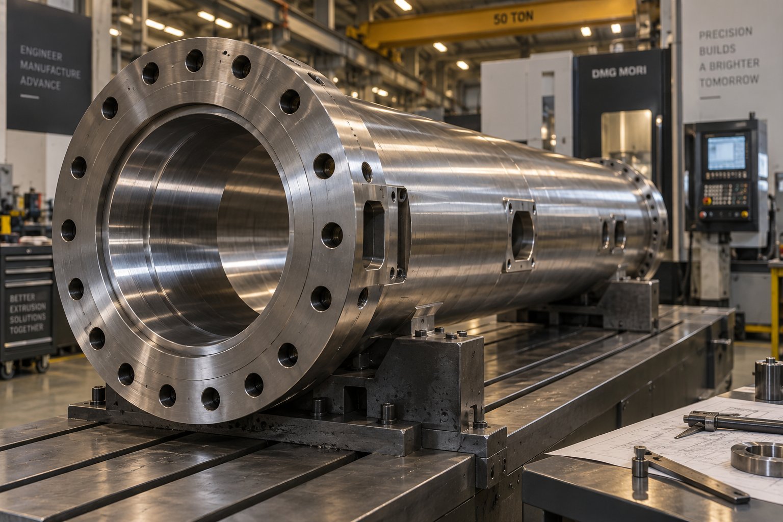
Inside an Extruder Barrel Manufacturer: From Raw Steel to Replacement
Oct 28, 2026
Learn how an extruder barrel manufacturer turns raw steel into precision barrels — covering materials, bimetallic vs nitrided linings, wear modes, and supplier evaluation.
Read Article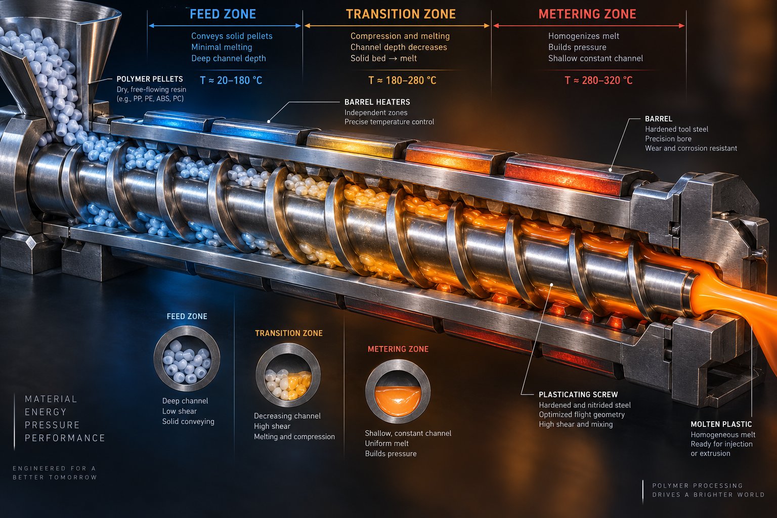
Screw Barrel Design Decoded: From Zone Geometry To Zero Defects
Oct 28, 2026
Master screw barrel design with this engineer's guide to zone geometry, polymer-specific parameters, material selection, defect troubleshooting, and simulation tools.
Read Article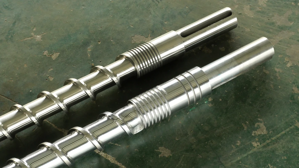
How The Wrong Extruder Screw Barrel For PP Ruins Your Melt
Oct 27, 2026
Learn why PP extrusion needs a purpose-built extruder screw barrel for PP — covering geometry, metallurgy, mixing elements, temperature profiles, and troubleshooting.
Read ArticleLooking for something else?
Search by material, symptom or product and jump straight to the relevant page.
These are navigation suggestions based on keyword matching — not a quotation, not a delivery commitment, and not a substitute for engineering review. Final specification is confirmed by our engineers against your drawings and processed material.
Need help with screw barrel selection?
Share your machine model, processed material and application. Our team can help with pricing and technical support.