

What Is a Screw Barrel and Why It Matters
Every plastic product you touch — from a water bottle cap to a car dashboard panel — began as raw pellets fed into a machine. The component responsible for transforming those pellets into a uniform, pressurized melt is the screw barrel. It is, without exaggeration, the heart of every extrusion and injection molding operation.
What Exactly Is a Screw Barrel
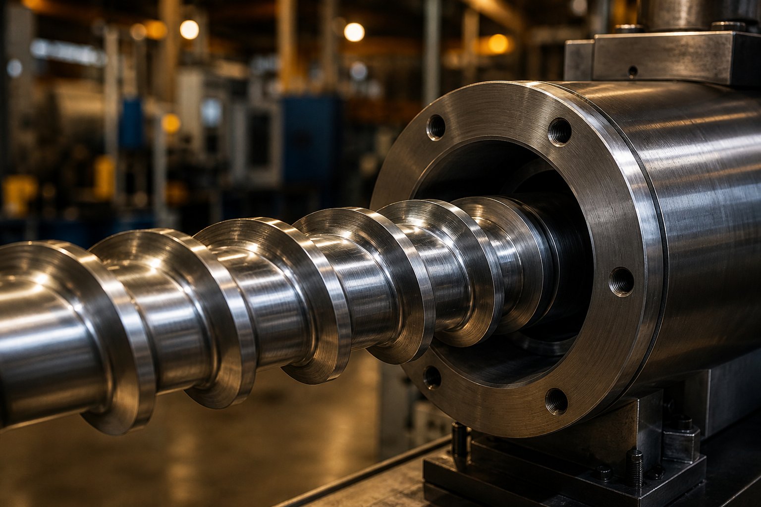
At its core, a screw barrel is a two-part assembly: a helical screw rotating inside a precision-machined cylindrical barrel. The screw features flights (the raised helical ridges), a root diameter (the central shaft), and channels (the spaces between flights) that convey material forward. The barrel — sometimes referred to informally as a screw tube — surrounds the screw with a hardened bore, multiple heating zones, and often a wear-resistant liner.
A screw barrel is the cylindrical assembly in which a helical screw rotates inside a precision-bored barrel to convey, melt, mix, and pressurize polymer material. It is the primary plasticating unit in injection molding machines and extruders, directly controlling melt quality, throughput, and energy efficiency.
Together, these two components generate roughly 80-90% of the mechanical energy needed to melt plastic — heater bands simply assist the process. That means the extruder screw barrel does far more than transport material; it actively creates the melt through shear, compression, and friction.
Why the Screw Barrel Matters to Your Operation
Imagine running a production line where cycle times creep upward, reject rates climb, and energy bills spike — yet no single alarm goes off. A worn or poorly matched set of extruder screws and barrels is often the invisible culprit behind these costly symptoms.
When a screw barrel performs well, the results are tangible:
- Melt quality — Consistent viscosity and temperature produce parts with uniform strength, clarity, and surface finish.
- Cycle times — Efficient plasticating means faster recovery and shorter overall cycles.
- Energy consumption — A properly designed screw tube assembly reduces drive load and heater compensation.
- Reject rates — Stable output minimizes short shots, black specks, and dimensional variation.
Performance, however, is never about a single variable. It depends on the interplay of three factors: the geometry of the screw and barrel, the metallurgy that resists wear and corrosion, and the operating conditions — temperature profiles, screw speed, back pressure — that the process demands every shift.
Understanding these fundamentals is the first step toward diagnosing problems before they drain your budget. The critical question, then, is which specific engineering parameters shape that geometry — and how do small changes in those numbers create large swings in output quality and throughput.
Key Technical Parameters That Control Screw Barrel Performance
Three numbers quietly dictate whether your screw barrel delivers flawless melt or sends you chasing rejects across the shop floor: L/D ratio, compression ratio, and metering depth. Sounds technical? It is — but the logic behind each one is surprisingly straightforward once you strip away the jargon.
L/D Ratio and Its Effect on Melt Quality
L/D ratio simply means the flighted length of the screw divided by its diameter. A 90-mm extruder screw with a flighted length of 2,700 mm has an L/D of 30:1. That single ratio tells you how long polymer stays inside the barrel and how much mixing energy it receives along the way.
For single-screw extruders, you'll typically see L/D values between 20:1 and 36:1. A longer L/D gives the melt more residence time and shear history, which generally improves homogeneity — especially important with color concentrates or additive-loaded formulations. The trade-off? A longer barrel costs more to manufacture, draws more drive energy, and increases the thermal load the cooling system must manage.
In injection molding, most general-purpose machines run an injection screw with an L/D between 20:1 and 25:1. That shorter ratio reflects the reciprocating action of an injection molding screw, where the screw both plasticates and injects, so residence time is partly controlled by cycle timing rather than barrel length alone.
Compression Ratio and Metering Depth Explained
Compression ratio is the feed-zone channel depth divided by the metering-zone channel depth. Imagine the channel between flights as a moving container: if it starts 9 mm deep at the feed throat and shrinks to 3 mm at the metering section, your compression ratio is 3:1.
That shrinking channel does three things simultaneously — it compacts pellets to squeeze out trapped air, presses polymer against the hot barrel wall for efficient heat transfer, and generates shear heat that completes melting. Research published by Dow found that for LLDPE pellet feedstocks, an optimal compression ratio of about 2.8 balances melting capacity against discharge quality, while ratios above 2.8 tend to produce higher discharge temperatures and increased flight wear.
The principle is intuitive: crystalline polymers like PE and PA need more shear energy to break through their ordered molecular structures, so they favor higher compression. Amorphous and heat-sensitive materials — PVC being the textbook case — demand lower compression to avoid scorching. Getting the compression ratio injection molding screw match right is just as critical as it is in extrusion, because excessive shear in a reciprocating barrel translates directly into degraded part properties.
Metering depth, the actual channel depth in the final metering zone, controls output rate and melt temperature independently of compression ratio. A deeper metering channel increases throughput but raises melt temperature due to greater shear volume; a shallower channel tightens temperature control at the expense of rate.
The table below shows typical starting-point values for common polymer families. Keep in mind that these are general ranges — always confirm against your material supplier's processing datasheet and your specific machine geometry.
| Polymer | Typical L/D Ratio | Compression Ratio | Metering Depth (mm)* |
|---|---|---|---|
| PE (HDPE / LDPE / LLDPE) | 24:1 – 30:1 | 2.8 – 4.0:1 | 2.5 – 4.0 |
| PP | 24:1 – 30:1 | 2.5 – 3.5:1 | 2.5 – 4.0 |
| PVC (rigid) | 20:1 – 24:1 | 2.0 – 2.5:1 | 3.0 – 4.5 |
| PA (Nylon) | 24:1 – 30:1 | 3.0 – 3.5:1 | 2.0 – 3.5 |
| PC | 22:1 – 28:1 | 2.0 – 2.8:1 | 2.5 – 4.0 |
| *Metering depths are approximate for mid-range screw diameters (50–90 mm). Larger-diameter screws scale proportionally. Confirm values against OEM and resin supplier recommendations. | |||
How Changing Parameters Affects Throughput
What happens when these parameters miss the mark? The failures follow a predictable pattern:
- Compression too high — Excessive shear heat degrades heat-sensitive resins, produces scorching and black specks, and accelerates screw flight wear near the transition zone. You may also see elevated discharge temperatures that narrow your processing window.
- Compression too low — The metering channel runs partially empty, causing output surging and pressure instability. Unmelted pellets pass through the injection screw or extruder screw tip, showing up as gels in film or weak spots in molded parts.
- Metering depth too shallow — Throughput drops and melt temperature rises, forcing longer cycles and higher energy costs.
- Metering depth too deep — Output increases but melt uniformity suffers, especially at high screw speeds where the melting flux cannot keep pace with conveying capacity.
The critical takeaway is that these parameters never work in isolation. Changing one shifts the balance of the others, which is why a screw barrel that performs brilliantly on polypropylene can produce disastrous results the moment you switch to polycarbonate without adjusting the geometry.
Geometry, however, is only half the equation. The configuration of the screw itself — whether a single-screw design or a modular twin-screw arrangement — determines which geometries are even possible and how flexibly you can adapt to different materials and process goals.
Single-Screw vs Twin-Screw Barrel Compared
A screw barrel optimized for steady polyethylene pipe extrusion will look nothing like one built to compound glass-fiber-reinforced nylon. The difference starts not with dimensions or metallurgy but with a more fundamental question: how many screws are rotating inside the barrel? That single decision — one screw or two — shapes every downstream choice about mixing intensity, maintenance budgets, and material flexibility.
Single-Screw Barrel Configurations
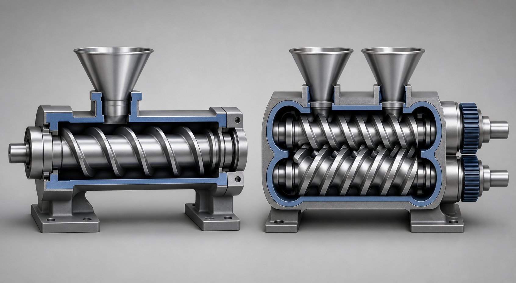
The single extruder screw is the workhorse of plastics processing. One helical screw rotates inside a smooth-bore barrel, relying on friction between the polymer and the barrel wall to drag material forward. The classic design divides the screw into three functional zones:
- Feed zone — Deep channels accept pellets or granules from the hopper and begin conveying them forward.
- Transition (compression) zone — Channel depth gradually decreases, compacting the material against the heated barrel wall to squeeze out air and initiate melting.
- Metering zone — A shallow, constant-depth channel homogenizes the melt and builds the pressure needed to push it through the die or nozzle.
This three-zone layout handles the vast majority of general-purpose extrusion and injection molding jobs. When a process demands better melting efficiency, barrier screws add a secondary flight in the transition zone that separates the solid bed from the melt pool, preventing solid-bed breakup — one of the leading causes of output surging.
Need even more mixing without switching to a twin-screw platform? Distributive and dispersive mixing sections — such as Maddock mixers, pineapple elements, or cavity-transfer designs — can be added to the metering zone. These elements improve color dispersion and additive distribution while keeping the simplicity and lower cost of a single-screw system. As one practical selection guide notes, for many pipe, tube, and profile lines using stable pellets, a single-screw setup is the more suitable architecture because it provides steady melting, pressure, and output with lower complexity.
Twin-Screw Barrel Configurations
Where a single screw extruder relies on friction-driven drag flow, a twin screw barrel uses two intermeshing screws that physically push material forward through positive displacement. That mechanical difference unlocks an entirely different level of mixing control — but it also introduces design complexity you need to understand before committing capital.
Twin-screw systems split into two families based on rotation direction:
- Co-rotating (screws turn the same way) — Fully intermeshing geometry creates a self-wiping action that virtually eliminates dead zones and stagnation. Material is forcibly handed from one screw flight to the next at the intermeshing region, generating intense shear fields ideal for compounding, reactive extrusion, and nanocomposite dispersion. The co-rotating configuration also keeps the residence time distribution narrow — critical when processing thermally sensitive polymers or running reactive chemistry inside the barrel.
- Counter-rotating (screws turn in opposite directions) — Material is drawn into the intermeshing zone and advanced under compression rather than high shear. A calendering effect at the nip point disperses additives gently, keeping shear heating low. This makes counter-rotating designs particularly well suited for rigid PVC, where the gap between processing temperature and degradation temperature is dangerously thin.
What really sets the twin screw and barrel apart from its single-screw counterpart is modularity. Instead of one monolithic screw, twin-screw systems use segmented screw elements — conveying elements, kneading blocks, reverse elements, and distributive mixers — that slide onto a common splined shaft. The barrel itself is segmented too, with individual sections that can include solid barrels, vented barrels, side-feed barrels for downstream filler addition, and liquid-injection ports. This modular architecture lets you reconfigure the same screw extruder for a different recipe without buying new hardware — just rearrange the elements.
Primary applications for twin-screw configurations include compounding (masterbatch, filled compounds, polymer alloys), reactive extrusion (grafting, polymerization), devolatilization (removing moisture, solvents, or monomers), and high-filler-loading processing where 40-80% mineral or fiber content would overwhelm a single-screw design.
Choosing the Right Configuration for Your Application
The table below puts both configurations side by side across the dimensions that matter most when specifying or replacing a screw barrel assembly. Use it as a starting framework — then validate against your specific material, throughput target, and budget constraints.
| Dimension | Single-Screw | Twin-Screw |
|---|---|---|
| Capital cost | Lower — simpler gearbox, single bore, fewer precision components | Higher — heavy-duty gearbox, dual-bore barrel, precision-intermeshing screws |
| Maintenance complexity | Straightforward — one screw to pull, one bore to measure, fewer wear parts | More involved — segmented elements to inspect, tighter tolerances to monitor, higher spare-parts inventory |
| Mixing capability | Low to moderate; improved with barrier flights and mixing sections | Moderate to high; kneading blocks and modular elements provide intense dispersive and distributive mixing |
| Throughput flexibility | Optimized for a narrower operating window; output closely tied to screw speed | Broader operating window; output can be decoupled from screw speed using starve-feeding |
| Feedstock suitability | Best with pellets and pre-compounded granules | Handles powders, fluff, recycled regrind, and variable-bulk-density feeds effectively |
| Polymer suitability | PE, PP, PS, PET, compounded PVC pellets, most thermoplastics from pellet form | PVC dry blends (counter-rotating), filled compounds, engineering alloys, bioplastics, recycled streams |
| Typical industries | Pipe, profile, sheet, blown film, injection molding | Compounding, masterbatch, automotive compounds, pharmaceutical, food-grade specialty processing |
The common mistake — and the most expensive one — is treating twin-screw as inherently "better." If your line runs pre-compounded PE pellets into pipe, a twin-screw system adds cost, cleaning time, and operator complexity without delivering proportional value. Conversely, trying to compound a 60% calcium-carbonate-filled masterbatch on a single-screw platform will produce poor dispersion, inconsistent filler distribution, and elevated scrap rates no matter how well the screw is designed.
Configuration choice should always follow the material and the process goal — not habit, brand loyalty, or assumptions about sophistication. Ask two questions first: Is the extruder expected to do the mixing, or has the material already been compounded? And can the feedstock generate enough barrel-wall friction to move forward on a single screw, or does it need positive displacement? Those answers will point you in the right direction far more reliably than any spec sheet.
Whichever configuration you choose, its service life depends heavily on what the screw and barrel are actually made of. The materials and surface treatments applied to these components determine how long they resist the abrasive fillers, corrosive off-gases, and relentless mechanical stress that every plastics process inflicts — shift after shift.
Screw Barrel Materials and Surface Treatments That Maximize Life
Geometry gets the design right. Metallurgy keeps it running. Two screw barrels with identical dimensions can deliver wildly different service lives depending on the steel grades, liner alloys, and surface treatments chosen during manufacturing. The problem is that material selection is often treated as a cost decision — pick the cheapest option that "should" work — when it is really an engineering decision that drives total cost of ownership for years after the purchase order is signed.
Base Metal Options for Screws and Barrels
Every extruder barrel and screw starts with a base steel, and three families dominate the industry. Each suits a different balance of strength, hardness, and operating temperature.
Nitrided alloy steels — grades like 4140 and 38CrMoAlA — are the most widely used base materials in screw barrel manufacturing. After gas nitriding, these steels develop a hardened surface layer (typically 65-72 HRC at the case) that resists moderate wear and mild corrosion. The underlying core remains tough enough to absorb the cyclic mechanical loads of extrusion and injection molding. For processing unfilled polyolefins, polystyrene, or pre-compounded pellets, a properly nitrided 38CrMoAlA screw barrel delivers reliable performance at the lowest upfront cost. That makes it the default starting point for the majority of general-purpose applications.
The catch? The nitrided layer is thin — only a few thousandths of an inch. Once abrasive fillers grind through it, or once you regrind a worn screw to restore dimensions, that hardened surface is gone and you are running on softer core steel.
Tool steels — H13 and D2 being the most common — step in when the demands exceed what nitrided alloy steel can handle. H13 maintains its hardness and toughness at elevated temperatures, making it a strong candidate for injection molding screws running engineering resins at high melt temperatures or for barrel extruder components subjected to intense thermal cycling. D2, a high-chromium cold-work steel, offers superior abrasion resistance and is sometimes used for screw elements in compounding applications. Hardness ranges of 48-62 HRC (depending on tempering) give tool steels a meaningful edge in abrasive environments, though their higher raw material and machining costs limit them to applications where nitrided steel falls short.
Stainless steels occupy a niche role — primarily in food-grade, pharmaceutical, and fluoropolymer processing — where corrosion resistance trumps all other considerations. They are softer than nitrided or tool steels, so they wear faster in abrasive service, but their resistance to chemical attack from aggressive resins and cleaning agents justifies the trade-off in corrosion-dominated environments.
Bimetallic Barrel Liners and Their Advantages
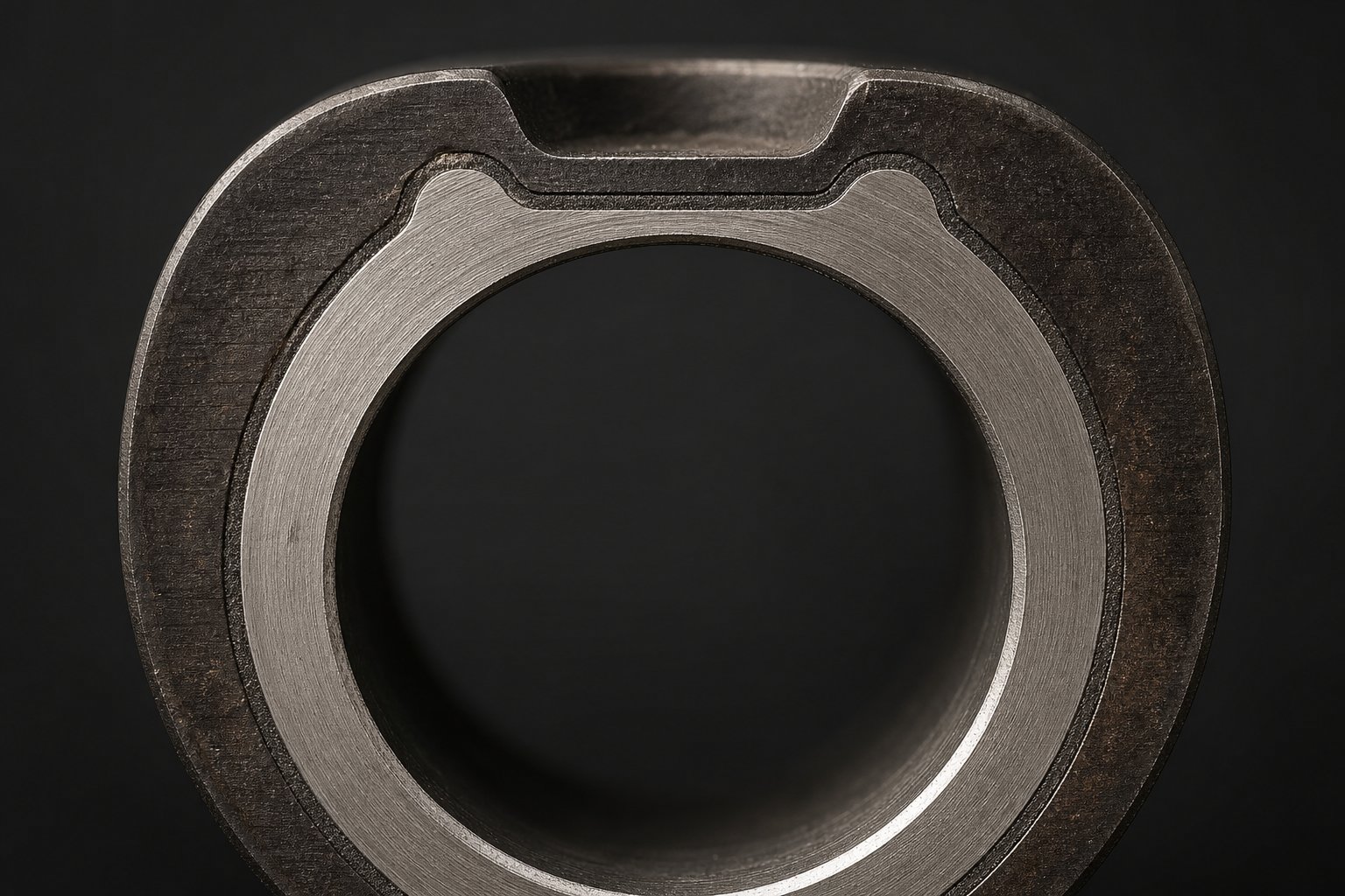
When you picture a standard extrusion barrel, you might imagine a solid tube of steel with a bored hole through the center. A bimetallic barrel looks the same from the outside, but its inner bore tells a different story. During manufacturing, a wear-resistant alloy is centrifugally cast inside the structural barrel body. The barrel spins at high speed while molten alloy is poured in, forcing the alloy outward against the bore wall where it solidifies into a metallurgically bonded liner — not a coating that can peel, but an integral layer fused to the base steel.
The liner alloy is where the real engineering happens, and the choice depends entirely on whether your primary enemy is abrasion, corrosion, or both:
- Nickel-based alloys — Provide a strong balance of wear resistance and corrosion resistance. They are the go-to choice for processing PVC (where hydrochloric acid attacks barrel surfaces), flame-retarded compounds, and mildly abrasive recycled streams. Industry guidance from Plastics Technology confirms that nickel-rich boron alloys can handle even aggressive fluoropolymers.
- Cobalt-based alloys (e.g., Stellite grades) — Offer excellent wear resistance and maintain hardness at high temperatures. They suit applications with metal-to-metal contact and moderate abrasion but provide less corrosion protection than nickel-based alternatives.
- Tungsten carbide blends — Deliver the highest abrasion resistance available in a barrel liner. These alloys embed hard carbide particles in a nickel or cobalt matrix, making them the standard specification for extruder barrels processing high-glass-fiber compounds, heavy mineral fillers, or contaminated recycled materials where abrasive particles would chew through a nitrided bore in a fraction of the expected service life.
The upfront cost of a bimetallic barrel typically runs higher than a standard nitrided barrel — sometimes significantly so. Yet for abrasive or corrosive applications, that premium is often recovered many times over. A bimetallic barrel that lasts three or four times longer than a nitrided alternative may cost far less per operating hour once you factor in reduced downtime, fewer screw pulls, and consistent output quality across a longer service window.
Surface Treatments and Coatings That Extend Life
Beyond base metal and liner selection, surface treatments add another layer of protection — sometimes literally. Each treatment targets a specific threat, and choosing the wrong one is a surprisingly common and expensive mistake. You would not wear a raincoat into a sandstorm; the same logic applies here.
- Gas nitriding — Diffuses nitrogen into the steel surface to create a hard case. Primary benefit: moderate wear and corrosion resistance at the lowest cost. Limitation: the thin hardened layer (typically a few thousandths of an inch) is consumed by aggressive fillers and cannot survive regrinding.
- Hard chrome plating — Electroplates a thin, hard, low-friction chromium layer onto screw surfaces. Primary benefit: excellent corrosion resistance and improved material release, making it a standard choice for PVC processing. Limitation: limited abrasion resistance — glass fibers and mineral fillers grind through the chrome layer relatively quickly.
- PVD (Physical Vapor Deposition) coatings — Deposit ultra-thin ceramic films (TiN, CrN, or similar) that provide high surface hardness and chemical inertness. Primary benefit: outstanding release properties and moderate wear resistance in a barrel extruder environment with sticky or thermally sensitive resins. Limitation: thin film thickness means PVD is best suited as a complement to, not a replacement for, robust base metallurgy.
- Tungsten carbide thermal spray (HVOF) — Applies a dense carbide coating using high-velocity oxygen fuel spraying. Primary benefit: extreme abrasion resistance, ideal for flight lands on screws running heavy glass-fiber or mineral-filled compounds. Limitation: carbide alone does not resist corrosive chemical attack — if your process generates acidic off-gases, carbide needs to be paired with corrosion-resistant alloy chemistry underneath.
- Hardfacing (Stellite / Colmonoy weld overlays) — Welds a wear-resistant alloy onto screw flight crests. Primary benefit: thick, re-weldable protection that survives multiple rebuilds — unlike nitriding, which is gone after one regrind. Limitation: requires skilled application to avoid heat-affected-zone distortion, and alloy selection must match the specific threat (cobalt-based Stellite for general wear, nickel-based Colmonoy for combined abrasion and corrosion).
The pattern across all these options is consistent: corrosion threats call for chrome or nickel-based chemistry, abrasion threats call for carbide or hardfacing, and combined threats demand a layered strategy — typically a bimetallic extruder barrel paired with a hardened or coated screw. Spending on the wrong axis — carbide for a corrosion problem, chrome for an abrasion problem — wastes money and leaves the real enemy unaddressed.
Material selection is not about finding the most expensive option and hoping it covers everything. It is about diagnosing whether your process attacks components through corrosion, abrasion, or both — then engineering the right combination of base steel, liner alloy, and surface treatment to match. That diagnostic thinking applies not just when specifying new equipment but also when evaluating wear on components already in service — a skill that separates reactive maintenance teams from proactive ones.
Screw Barrel Applications Across Plastics Processing
A perfectly engineered screw barrel sitting in the wrong application is just expensive steel. Metallurgy and coatings protect the hardware, but the real performance question is whether the design matches the demands of the specific process it serves. Those demands vary dramatically — from the rapid reciprocating action of injection molding to the continuous throughput of blown film, and from commodity polyolefins to FDA-regulated food packaging. Understanding how each application stresses the screw and barrel differently helps you specify smarter, maintain more effectively, and avoid costly mismatches.
Screw Barrels in Injection Molding Equipment
Injection molding places a unique set of demands on the screw barrel that no other plastics process replicates. Unlike continuous extrusion, the screw in an injection molding barrel performs double duty: it rotates to plasticize resin, then stops rotating and plunges forward like a piston to inject the melt into the mold cavity at pressures that can exceed 20,000 psi.
That reciprocating action means the screw must withstand both torsional stress during plasticating and high compressive loads during injection. As Michigan CNC Machining Parts explains, the reciprocating screw generates 60-90% of the heat needed to melt the polymer through friction and shear alone — heater bands merely supplement the process. Shot-to-shot consistency depends heavily on the check-ring assembly at the screw tip. When the screw plunges forward, the check ring seats against a thrust ring to seal off backflow, ensuring repeatable shot weights. A worn or damaged check ring allows melt to leak backward past the screw tip, producing short shots, inconsistent part weights, and dimensional variation that no amount of process adjustment can compensate for.
Injection molding screws also tend toward shorter L/D ratios (20:1 to 25:1) compared to extrusion screws because cycle timing — not barrel length — controls much of the residence time. Selecting the right injection molding screws and barrels for your resin and part geometry is one of the highest-leverage decisions an injection molder can make.
Screw Barrels in Extrusion Lines
Extrusion is a continuous process, and that changes everything about how the screw barrel is loaded. There is no injection stroke, no cycling between plasticating and packing — the screw simply rotates, melts, and pumps, hour after hour. The challenge shifts from shot-to-shot consistency to sustained output stability and melt uniformity over extended production runs.
Each extrusion application imposes its own geometry and thermal management requirements:
- Sheet and flat film — Demand tight melt-temperature uniformity across the die width. A plastic extrusion screw for sheet lines typically runs a longer L/D (28:1 to 34:1) with enhanced mixing sections to eliminate thermal gradients that would produce gauge variation.
- Pipe and profile — Require high and stable melt pressure to fill complex die geometries consistently. Barrier screws with grooved-feed barrels are common here, as they improve melting efficiency and reduce output surging.
- Blown film — As SpecialChem's extrusion guide details, the extruder pumps melt into an annular die to form a bubble that is air-cooled and collapsed. Any inconsistency in melt temperature or viscosity shows up immediately as thickness variation in the film. Screw design must prioritize melt homogeneity above raw throughput.
- Blow molding — The screw barrel feeds a parison die or accumulator head. Intermittent-extrusion blow molding creates cyclic loading similar to injection molding, so the plastic extruder screw must handle both continuous plasticating and periodic high-pressure surges.
In every case, barrel heating and cooling zones must be configured to match the screw geometry. A high-performance screw plastic extruder running the wrong thermal profile will still produce inconsistent melt — no matter how well the screw is designed.
Specialty and Food-Processing Applications
Beyond standard thermoplastics, screw barrels serve applications where material chemistry and regulatory requirements add layers of complexity. Rubber processing, for instance, subjects barrels to aggressive compounds with sulfur-based curatives that accelerate corrosive wear. Recycling operations feed contaminated, inconsistent-bulk-density regrind that can include metal fragments, paper labels, and abrasive particulates — all of which punish screws and barrels far more severely than virgin pellets.
Food-grade processing introduces an entirely different constraint set. Barrels and screws must be manufactured from FDA-compliant materials — typically stainless steel or barrels with food-safe coatings — and must be designed for thorough cleaning to prevent microbial contamination between runs. Non-toxic surface treatments replace conventional nitriding or chrome plating where direct food contact is possible.
Here is a quick-reference list matching application types to recommended screw barrel features:
- Injection molding (general-purpose) — Nitrided alloy steel screw, standard bimetallic barrel, precision check-ring assembly
- Injection molding (glass-filled engineering resins) — Tool-steel or hardfaced screw flights, tungsten carbide bimetallic barrel liner
- Sheet / film extrusion — High-L/D screw with barrier and mixing sections, multi-zone barrel with precision temperature control
- Pipe and profile extrusion — Barrier screw design, grooved-feed barrel section, bimetallic liner for long-run durability
- PVC processing — Low-compression screw, chrome-plated flights, nickel-alloy bimetallic barrel for corrosion resistance
- Food-grade / pharmaceutical — Stainless steel construction, FDA-compliant coatings, easy-disassemble design for cleaning validation
- Recycling — High-wear bimetallic barrel, hardfaced screw flights, vented barrel sections for devolatilization
Manufacturers like NANHAIYA offer application-specific screw and barrel solutions spanning injection molding, extrusion, and specialty configurations — helping plastic processors and equipment manufacturers source custom or replacement components engineered for their exact process requirements.
Matching the right screw barrel to your application is step one. Keeping it performing at that level requires something equally important — knowing exactly when wear begins stealing output quality, and having the measurement data to prove it before the losses show up in your reject bins.
Recognizing Screw Barrel Wear and When to Take Action
Wear never announces itself with an alarm. Instead, it creeps in — a slow, invisible widening of the gap between screw flight and barrel wall that quietly steals output, inflates energy bills, and degrades part quality long before anyone thinks to pull the screw and take a measurement. The difference between a reactive maintenance team and a proactive one comes down to two skills: recognizing how wear presents itself and knowing how to measure it accurately.
Common Wear Patterns and What They Reveal
Not all screw and barrel wear looks the same, and misidentifying the pattern leads you straight to the wrong fix. Three distinct mechanisms account for nearly every case you will encounter on the shop floor, and each one leaves a different fingerprint on the metal surfaces.
- Abrasive wear — Hard particles in the resin literally grind away metal surfaces. Glass fibers, calcium carbonate, silica, and mineral fillers are the primary offenders. You will notice relatively uniform bore enlargement along the barrel length, concentrated wherever channels carry high solids content. On the screw, flight outer diameters shrink evenly as the hard facing is slowly abraded away. As extrusion experts at Plastics Technology note, abrasive fillers cause particularly aggressive wear where solids wedge at the end of the melting section or at the entry to mixing elements, creating momentary blockages that push the screw into the barrel wall.
- Adhesive wear — This is metal-to-metal contact, and it happens when the screw physically touches the barrel bore. Causes include improper alignment, incompatible geometries, or a bent screw. The telltale signs are localized galling marks, scoring lines, and uneven wear concentrated on one side of the barrel or along specific flight crests. If you see bright, polished streaks on the screw OD opposite roughened patches on the barrel wall, adhesive wear is the culprit.
- Corrosive wear — Chemical attack from degraded resin off-gassing. PVC processing is the textbook example: hydrogen chloride released during thermal degradation reacts with barrel and screw surfaces, producing pitting and etching rather than smooth material removal. Fluoropolymers generate hydrofluoric acid, which is even more aggressive. Unlike abrasive wear's uniform pattern, corrosive damage concentrates near vent ports, at the transition zone where material temperature spikes, and at any dead spots where stagnant melt degrades over time.
In practice, most extruder screw and barrel assemblies experience a combination of these mechanisms. A glass-filled PVC compound, for instance, delivers abrasive and corrosive attack simultaneously — demanding both carbide-grade abrasion resistance and corrosion-resistant alloy chemistry in the barrel liner. Identifying which mechanism dominates tells you whether to invest in harder metallurgy, better corrosion protection, or improved alignment — rather than guessing.
How to Measure Screw and Barrel Wear
Visual inspection catches the obvious problems — pitting, scoring, cracked flights — but it cannot tell you whether you are 10% into the wear life or 90%. Only dimensional measurement does that. Fortunately, the process is straightforward if you follow a consistent method.
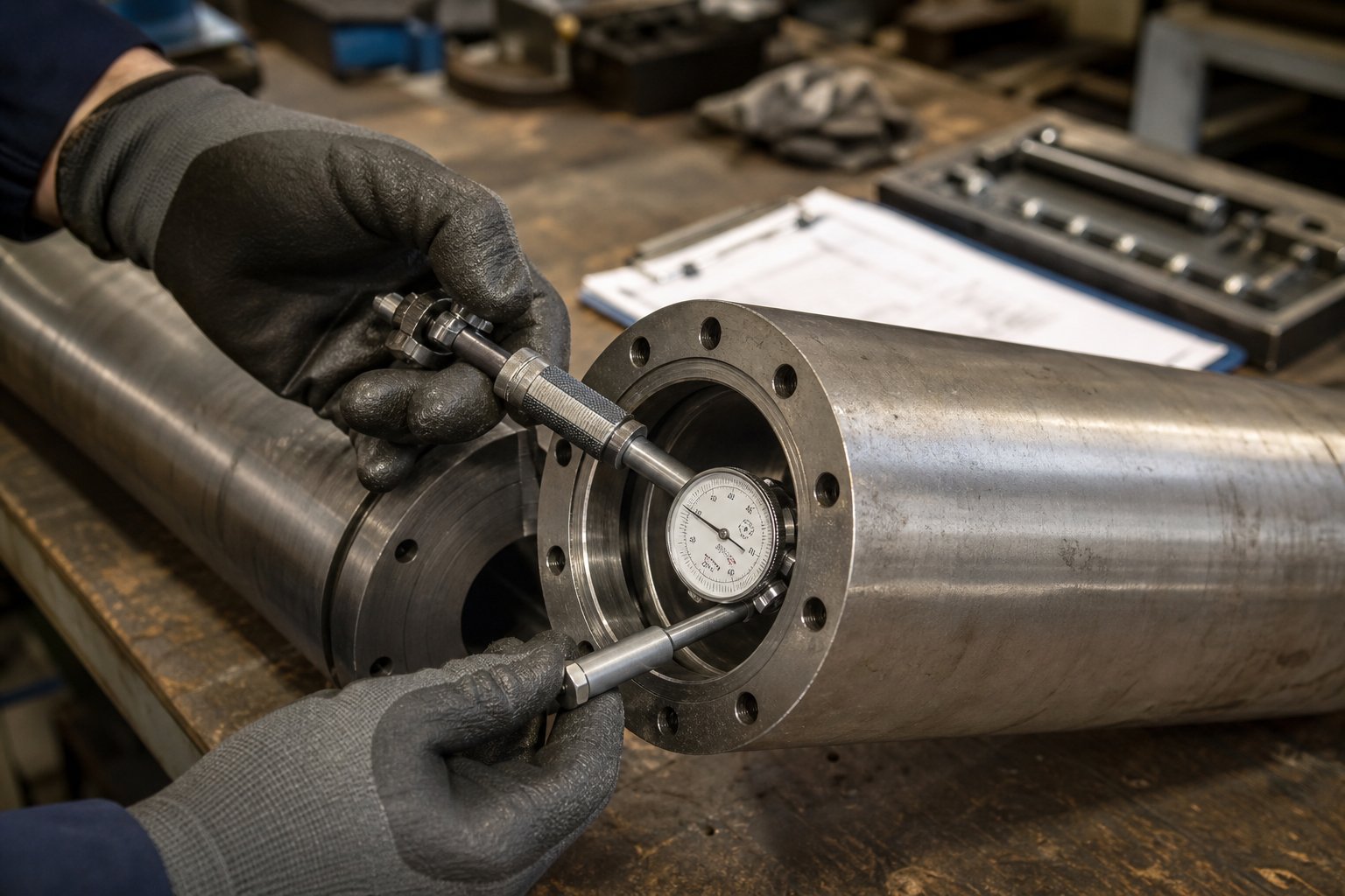
Measuring the barrel: Use a telescoping bore gauge (or an internal micrometer for larger bores) to measure the barrel inner diameter. Take readings at multiple points along the barrel length — every 2 to 4 diameters is a practical interval — and record both vertical and horizontal measurements at each station to detect ovality. Compare every reading against the original bore specification. As Davis-Standard's maintenance guidelines emphasize, measure as far down each end of the barrel as possible to capture wear near the feed throat and discharge, where conditions often differ.
Measuring the screw: Clean the screw thoroughly — brass tools and copper gauze only, never steel wire brushes or aggressive abrasives that could damage the surface. Place the screw on a clean, flat surface (a granite table is ideal for checking straightness by rolling the screw and watching for bowing). Use an OD micrometer with a parallel bar that spans across two flights to measure the outer diameter of the screw at each zone. Record measurements at intervals along the length and compare to the original flight OD specification.
The general guideline for new screws and barrels: flight clearance per side equals the nominal screw diameter divided by 1,000. A 3.5-inch screw, for example, starts with roughly 0.0035 inches of clearance per side. Anything beyond that original specification is wear.
The table below provides general tolerance thresholds for evaluating wear severity. Keep in mind that these are guidelines — specific tolerances vary by equipment manufacturer, screw design, and application criticality.
| Wear Zone | Flight Clearance (per side) | Condition | Recommended Action |
|---|---|---|---|
| Nominal (new) | Diameter / 1,000 | Within OEM specification | No action required — document baseline measurements |
| Acceptable wear | Up to 2x nominal clearance | Minor performance reduction possible; output still within spec | Continue monitoring at regular intervals; schedule next measurement |
| Caution zone | 2x to 4x nominal clearance | Noticeable output loss, rising discharge temperatures, possible surging | Plan rebuild or replacement; order spare screws and barrels to avoid emergency downtime |
| Replacement required | Beyond 4x nominal clearance or hard facing fully worn through | Significant rate reduction, poor melt quality, excessive energy draw | Replace immediately — continued operation risks further damage and scrap |
| Note: Critical-duty processes (e.g., medical, optical) may require action at lower wear thresholds. High-work barrier screws typically limit wear to 75% of barrier flight clearance. Always consult OEM specifications for your equipment. | |||
Interpreting Measurement Data for Action
A single set of measurements tells you where you stand today. Trending those measurements over time tells you where you are headed — and that is far more valuable.
Here is why the gap matters so much: as clearance between the screw flight OD and the barrel wall increases, polymer melt leaks backward over the flights instead of being pushed forward. This backflow — sometimes called "leakage flow" — directly reduces pumping efficiency. The extruder drive compensates by working harder, drawing more amperage and generating excess shear heat. You will see discharge temperatures climbing even though your barrel heater setpoints have not changed. Output drops at a given screw speed, so operators crank up RPM to maintain rate, which accelerates wear further in a self-reinforcing cycle.
Practical impact? Data from Dow's extrusion research showed that on a 100-mm screw running 1 MI polyethylene, increasing flight clearance from 0.005 inches (new) to 0.016 inches forced a screw speed increase that raised discharge temperature by roughly 10 degrees Celsius. At that point, the blown film line could no longer maintain bubble stability at the original production rate, forcing a throughput reduction of up to 13% — a direct hit to profitability and capacity.
By recording measurements at consistent intervals — every screw pull, every scheduled shutdown, or at a fixed number of operating hours — you build a wear curve specific to your machine, material, and process. That curve lets you predict when clearances will cross from the caution zone into replacement territory, transforming screw and barrel changes from emergency scrambles into planned events with spare components already on the shelf. A spare screw kept in proper storage means the worn one comes out, the fresh one goes in, and your line is back up in hours rather than weeks.
Measurement data also reveals whether wear is accelerating — a sign that the hard facing has worn through and the softer base metal underneath is eroding rapidly. When you see that inflection point in your trending data, the replacement clock is ticking much faster than the early wear phase suggested.
Knowing how to spot and measure wear puts you in control of the timeline. The next question is equally practical: what daily, monthly, and annual maintenance habits keep that timeline as long as possible — and prevent the kind of damage that no measurement program can reverse?
Preventive Maintenance That Extends Screw Barrel Service Life
Pulling a worn screw for measurement is reactive — it confirms damage already done. The real opportunity lies in the hundreds of operating hours between those measurements, where small, consistent maintenance habits slow the wear curve and keep your barrel and screw performing closer to original specifications for significantly longer. Yet walk through most processing plants, and you will find that preventive maintenance on the plasticating system is either informal ("we check it when something feels off") or buried inside a generic machine PM schedule that gives no specific guidance on how to care for screws, barrels, or the melt path.
That gap is expensive. Reiloy USA's Preventative Maintenance Handbook puts it plainly: routine PM is often sacrificed to meet current demand, and while short-term production targets get hit, the long-term impact of deferred maintenance can be devastating to a business. The fix is a tiered framework that matches task complexity to inspection frequency — so the daily items take minutes, not hours, and the deeper assessments happen on a planned schedule rather than during an emergency.
Establishing a Screw Barrel Maintenance Schedule
Think of your maintenance schedule in three tiers. Each tier builds on the one before it, and skipping the daily basics makes the monthly and annual checks far less effective because problems that should have been caught early have already cascaded into measurable damage.
- Daily checks (operator-level, 5-10 minutes per shift)
- Monitor the temperature profile across all barrel zones. Look for zones that are consistently overriding their setpoints — a zone running hotter than commanded often means the heater band is compensating for poor screw pumping efficiency, an early signal of clearance growth.
- Record motor amperage or drive load at a fixed screw speed and throughput. Rising amperage at constant output is one of the earliest measurable indicators that extruder screws are losing pumping efficiency due to wear.
- Watch discharge pressure and melt temperature at the die or nozzle. Upward trends in melt temperature at stable setpoints point to excess shear from worn flights.
- Note any unusual noise, vibration, or feed irregularity. These are symptoms you can document without stopping the line.
- Monthly inspections (maintenance technician, during scheduled screw pulls or material changes)
- Perform a visual inspection of the screw when it is pulled for cleaning or changeover. Look for scoring, galling, cracked flights, or discoloration that indicates corrosive attack.
- Take spot-check measurements of screw flight OD at the feed, transition, and metering zones. Compare against baseline records.
- Inspect the feed throat and first barrel zone for bridging residue, embedded pellets, or signs of premature melting.
- Check heater bands for secure contact and proper torque on band clamps — loose bands create cold spots that alter melt behavior and stress nearby zones.
- Annual comprehensive assessments (maintenance engineer or OEM specialist)
- Conduct a full dimensional survey of the barrel bore using a telescoping bore gauge at intervals every 2-4 diameters along the length. Record both vertical and horizontal readings for ovality detection.
- Measure screw flight OD, root diameter, and straightness (roll test on a granite surface) across the entire screw length.
- Perform a metallurgical spot assessment — check for nitriding layer depletion on critical wear surfaces, and evaluate whether hard facing is intact or worn through to base metal.
- Review the full year of trending data (amperage, temperatures, output rates) against dimensional findings to calibrate your wear prediction model for the next cycle.
For lines running abrasive or reinforced resins, industry best practice recommends starting with six-month inspection intervals until wear trends are established — then adjusting based on actual data. Unfilled resin operations can typically begin with annual comprehensive assessments and extend or tighten the schedule as trending dictates.
Proper Cleaning and Purging Procedures
Every color change, material transition, and planned shutdown is an opportunity to either protect the barrel bore or damage it. The method you choose matters more than most operators realize.
Commercial purging compounds (CPCs) are engineered specifically for this job. High-quality CPCs scrub carbon deposits, color residue, and degraded resin from screw channels and barrel walls without damaging metal surfaces. Some formulations cool and shrink during purging, physically pulling built-up carbon away from the metal — a property that reduces the need for manual screw pulls. Others are thermally stable enough to serve as shutdown sealants, filling the barrel with a protective resin layer that prevents oxidation and carbon formation during idle periods. As Dyna-Purge's technical team explains, a technically competent CPC provider can match the proper grade to your resin, temperature range, and process type for optimal results — and the net cost-to-purge is typically lower than using virgin or regrind because less material is needed.
Natural resin purging — running virgin PE or PP through the system — works for simple color changes between compatible materials. It is inexpensive and readily available. The limitation is that natural resin lacks the scrubbing chemistry and mechanical action of a dedicated CPC, so it leaves more residue in dead spots, around check rings, and in the negative-flow areas behind mixing elements. For routine transitions on single-resin lines, natural purging may be sufficient. For critical changeovers, shutdown sealing, or any process running corrosive or heavily filled materials, a CPC is the better investment.
Abrasive purging methods — using glass-bead compounds, crushed walnut shell, or similar materials to physically scour the bore — should be approached with extreme caution. While effective at removing stubborn deposits, abrasive purges can scratch bore surfaces, damage bimetallic liners, and accelerate wear on extrusion barrels and screw flights. Reserve abrasive methods for situations where chemical purging has already failed, and always consult your screw and barrel supplier before using them.
Proper shutdown procedure is equally important. Never leave corrosive resins like PVC or flame-retarded compounds sitting in a hot barrel during idle periods. Purge with a thermally stable, non-corrosive compound before shutting down. If the machine will be idle for more than a few hours, reduce temperatures gradually rather than cutting heaters abruptly — thermal shock can warp barrels and stress welds on bimetallic liners.
Storage and Handling Best Practices
Spare extruder screws and barrels represent significant capital sitting on a shelf. Proper storage protects that investment; careless handling destroys it before the component ever sees service.
Anti-corrosion measures: Apply a rust-preventive coating or vapor-phase corrosion inhibitor (VCI) to all machined surfaces before storage. Wrap components in VCI-treated paper or plastic, and store in a climate-controlled area where temperature and humidity swings are minimized. Bare steel left in a damp warehouse will develop surface rust that pits the bore or flight lands — damage that is invisible under the corrosion but reduces the effective service life from day one.
Safe handling during screw pulls: Flight lands are precision-ground surfaces. Dragging a screw across a concrete floor, resting it on steel sawhorses without protective padding, or using steel tools to clean flight surfaces introduces nicks and scratches that become stress risers and accelerated-wear initiation points. Use brass or copper scrapers for cleaning, support screws on wooden or rubber-padded V-blocks, and never strike flights with hammers to break loose stuck material. When lifting, use proper slings rated for the weight — a large extruder screw can weigh hundreds of pounds, and dropping it even a short distance can bend the shaft or crack a hardened flight.
Systematic preventive maintenance can extend screw barrel service life by 30% or more while reducing unplanned downtime and maintaining the output quality your customers depend on — and it starts with the discipline of daily checks that take less time than a coffee break.
A well-maintained screw barrel still encounters problems on the shop floor. Output surges, black specks appear in molded parts, or energy consumption spikes without an obvious cause. When those symptoms show up mid-shift, the maintenance team needs a diagnostic path organized by what they can see — not by what they need a metallurgist to explain. That is where structured troubleshooting by symptom becomes the fastest route from problem to fix.
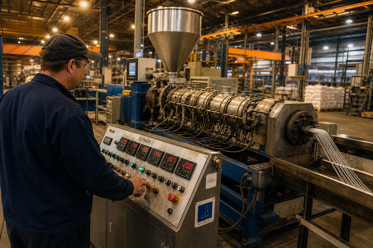
Troubleshooting Screw Barrel Problems by Symptom
You are mid-shift, the line is running, and something is clearly wrong — but the root cause is not obvious. Output is fluctuating, dark particles are showing up in finished parts, or the drive motor is pulling more amps than it should. In moments like these, a troubleshooting guide organized by technical cause is nearly useless because you do not know the cause yet. What you know is the symptom. Starting from what you can observe and working backward to the root cause is the fastest path to a fix.
Output Surging and Inconsistent Flow
Output surging — the oscillatory rise and fall of extruder output while setpoints remain constant — is one of the most common and disruptive problems in screw extrusion. When you see it, resist the urge to immediately adjust screw speed or temperatures. Instead, follow a systematic diagnostic path.
First, check screw wear clearances. Increased clearance between the extrusion screw flight OD and the barrel wall allows melt to leak backward over the flights, reducing net forward flow. This backflow creates cyclical pressure instability that manifests as surging at the die. If your last measurement data shows clearances approaching the caution zone from the wear table in the previous section, worn hardware is your most likely culprit.
Second, evaluate the extruder feed barrel zone for bridging. Material bridging — pellets fusing together above the feed throat or in the first few diameters of the screw channel — chokes the flow of incoming solids. You will see the screw intermittently starve, then refill, producing rhythmic surging. Look for a hot feed casing as a telltale sign. As Dow fellow Mark A. Spalding documents, the most common root cause for flow surging in smooth-bore extruders is improper temperatures in the solids conveying section — specifically, a feed casing that is too hot due to occluded cooling water channels or insufficient screw cooling. In one case study, extending the screw cooling hole to cover the full solids conveying length and installing a dedicated water pump completely eliminated the surging.
Third, assess the temperature profile for premature melting. If the first barrel zone temperature is set too high, pellets begin melting before they are fully compacted. The resulting thin melt film lubricates the barrel wall, reducing the friction that drives solids conveying. Output drops, the solids plug reforms, friction returns, output surges again — and the cycle repeats. The corrective action is straightforward: lower the first zone temperature to keep the feed section dry and ensure the feed casing feels warm, not hot, to the touch.
Black Specks and Contamination in the Melt Stream
Dark particles embedded in your product demand a different diagnostic approach because the same visual defect can originate from completely different sources. The critical first step — before you shut anything down — is to classify the contamination pattern.
Carbonized material from internal dead spots is the usual suspect when specks worsen with runtime or after a stop-start cycle. Polymer trapped in stagnation zones — behind mixing elements, in adapter transitions, or in the negative-flow areas of worn screw channels — degrades over time and periodically releases charred fragments into the melt stream. Worn screw geometry intensifies this problem because eroded flight lands and enlarged channel clearances create new pockets where material can hang up and degrade. The fix involves targeted purging with a commercial purging compound to remove built-up carbon, followed by a screw pull to inspect for dead spots created by wear. If stagnation zones are geometry-related (adapter design, die flow channels), those components need to be addressed directly.
External contamination from the feed system presents differently. If the specks correlate with a specific regrind batch, appear only after a material changeover, or change when you switch to clean virgin resin, the source is upstream — not inside the barrel. Common culprits include degraded regrind, conveying line residue, dust accumulation in hoppers, and packaging fragments. A five-minute visual inspection of a material sample from the hopper often identifies the problem before any disassembly is needed.
Excessive Energy Consumption and Overheating
When drive amperage climbs at constant screw speed and output, or when melt temperature rises even though barrel heater setpoints have not changed, worn flights are frequently the hidden driver. Here is the chain of events: as clearance grows, leakage flow over the flights increases. The screw must work harder to maintain the same net forward pumping rate. That extra mechanical energy converts directly into shear heat, raising melt temperature and forcing cooling systems to compensate. You end up paying for the same output twice — once through higher drive energy, and again through additional cooling.
Mismatched compression ratios compound the problem. Running a high-compression screw on a shear-sensitive amorphous resin generates more frictional heat than the material can absorb without degrading. The result is elevated melt temperatures, discoloration, and reduced physical properties in the finished product — all while the drive draws excess power. Conversely, too little compression leaves material partially unmelted, forcing downstream zones to finish the job through barrel heat alone, which is inherently less energy-efficient than shear-driven melting.
The troubleshooting matrix below organizes these symptoms into a quick-reference format. Print it and keep it near the operator station — when a problem appears mid-run, you will have a structured starting point instead of guesswork.
| Symptom | Likely Causes | Diagnostic Steps | Corrective Actions |
|---|---|---|---|
| Output surging / inconsistent flow | Worn screw flight clearances; feed-throat bridging; premature melting in feed zone; hot screw in solids conveying section | Review wear measurement data; check feed casing temperature (should be warm, not hot); verify screw cooling flow; inspect first-zone temperature settings | Replace worn screw or barrel; flush feed casing cooling channels; extend screw cooling hole to end of solids conveying section; reduce first-zone temperature |
| Black specks (worsen with runtime or after stop-start) | Carbonized material in dead spots; poor purging; degraded polymer in worn screw channels or adapter transitions | Observe whether specks increase with runtime or after restarts; purge with CPC and inspect output; pull screw to check for carbon buildup and stagnation zones | Purge with commercial compound; clean screw, adapter, and die flow channels; repair or replace worn screw geometry creating dead spots |
| Black specks (batch-related or constant) | Contaminated regrind; raw material defects; conveying system residue; inadequate screen filtration | Switch to clean virgin resin and observe; inspect material samples from hopper; check screen pack mesh size and sealing; review changeover purge history | Isolate contaminated batch; clean conveying lines and hopper; replace or tighten screen pack; increase regrind quality controls |
| Rising melt temperature at stable setpoints | Worn screw flights causing excess shear; compression ratio too high for current resin; mismatched screw geometry | Compare current drive amperage to baseline; check screw flight OD measurements; verify screw design matches the resin being processed | Replace worn screw; switch to screw geometry matched to current material; reduce screw speed if wear is moderate and replacement is scheduled |
| Excessive drive amperage / energy consumption | Worn flights reducing pumping efficiency; material bridging increasing torque demand; barrel heaters compensating for poor plasticating | Trend amperage against operating hours; check extruder feed barrel zone for bridging; compare current energy-per-kg against historical baseline | Replace worn screw and barrel; resolve feed-section thermal issues; evaluate screw design for proper compression and metering depth |
Every row in that matrix eventually points back to the same decision: can the worn or mismatched component be rebuilt to restore performance, or does the situation call for full replacement? That choice hinges on more than just the severity of wear — it involves the original metallurgy, the relevance of the current geometry, lead-time constraints, and a total cost calculation that extends well beyond the purchase price of new hardware.
Rebuild vs Replace — Total Cost of Ownership for Screw Barrels
Severity of wear is only one variable in a much larger equation. A screw barrel showing moderate flight erosion might be a perfect candidate for rebuilding — or a poor one, depending on the base metallurgy, the relevance of the original geometry, and whether your production schedule can absorb the lead time. Making the wrong call here is costly either way: rebuilding a component that should have been replaced wastes labor and delivers disappointing performance, while replacing one that could have been rebuilt throws away thousands of dollars in reusable material.
When Rebuilding Makes Economic Sense
Rebuilding restores worn components to serviceable condition through targeted metalworking processes. For screws, the most common techniques include PTA (plasma transferred arc) welding on flight crests, which deposits a dual-alloy composition of nickel, tungsten, and cobalt that can more than double service life compared to the original nitrided surface. Other options include surface hard chrome plating for improved flowability and corrosion protection, full-length polishing to address carburization, and straightening to correct shaft deflection caused by uneven loading.
For barrels, rebuilding typically involves boring the inner diameter back to true roundness and straightness using a horizontal boring machine, then grinding to a new oversize specification with a vertical honing machine. In some cases, the bore is re-nitrided or hard chrome plated after grinding to restore surface hardness.
Rebuilding makes economic sense when three conditions align:
- Wear is moderate — flight clearances are in the caution zone but hard facing has not worn completely through to base metal, and barrel bore ovality can be corrected without exceeding standard oversize limits.
- Base metallurgy is sound — no deep corrosive pitting, no fatigue cracks, and no heat damage from prior incidents. As experienced refurbishment suppliers emphasize, not all components benefit from rebuilding — excessive damage can render the process ineffective or even counterproductive.
- Screw geometry still matches current production needs — if you are running the same resin family and throughput targets as when the screw was originally designed, restoring dimensions makes sense. If your materials or process goals have shifted, rebuilding an obsolete design locks you into suboptimal performance.
A quality rebuild typically costs 40-60% of a new component while delivering 70-90% of new-component service life — a compelling value proposition when conditions are right. The key is an honest assessment upfront. Seeking advice from a supplier with both rebuilding capability and new-manufacturing expertise avoids the bias of a shop that only offers one solution.
When Full Replacement Is the Better Investment
Replacement wins in scenarios where rebuilding either cannot restore adequate performance or where the investment would be better directed toward improved technology. Here are the situations where a new screw barrel is the smarter path:
- Severe corrosive damage — deep pitting from PVC off-gassing or fluoropolymer attack compromises the structural integrity of the base metal. Welding over corroded surfaces produces unreliable bonds, and the underlying steel will continue to deteriorate.
- Obsolete geometry — the original screw design no longer matches your current material portfolio. If you have transitioned from unfilled resins to glass-filled engineering compounds, or from a single polymer to frequent changeovers across multiple families, a rebuilt screw with the old geometry will underperform a purpose-designed replacement.
- Process upgrades demand new design parameters — increased throughput targets, tighter melt-temperature tolerances, or new barrier and mixing-section technology may require a complete redesign that rebuilding cannot deliver.
- Base material quality is inadequate — a screw originally manufactured from basic nitrided steel running in an abrasive application will wear out again quickly after rebuilding. Replacement with a tool-steel or hardfaced design addresses the root cause rather than treating the symptom.
- Lead time and downtime risk — if rebuilding takes four to six weeks while a replacement can ship faster, the cost of extended downtime or degraded production may outweigh the savings from rebuilding.
When evaluating used extruders or considering whether to retrofit an older machine, the rebuild-versus-replace question becomes even more nuanced. Procurement teams sourcing a used twin screw extruder or used single screw extruders on the secondary market often inherit worn plasticating components that need immediate attention. In those cases, replacing the screw and barrel with new components engineered for the intended application — rather than rebuilding whatever came with the machine — typically delivers better long-term value. The same logic applies when upgrading a davis-standard extruder or similar legacy equipment: the machine frame and drive may have decades of life remaining, but the screw and barrel should be evaluated independently based on current production demands, not on what the previous owner was running.
Even when browsing listings for a used twin screw extruder for sale or a davis standard extruder for sale, factor in the cost of new or rebuilt plasticating components as part of the total acquisition price. A machine advertised at a bargain price with severely worn internals may cost more to bring online than a higher-priced unit with recently replaced screws and barrels.
Factors That Drive Screw Barrel Cost
Understanding what influences pricing helps you compare quotes intelligently — and avoid the trap of selecting the lowest invoice price without considering what that price buys in service life and performance.
| Cost Factor | How It Affects Price | Impact on Total Cost of Ownership |
|---|---|---|
| Diameter and length | Larger diameters and longer L/D ratios require more raw material, larger machining capacity, and longer production cycles | Proportional — bigger components cost more but serve higher-throughput processes that generate more revenue per hour |
| Base material | Tool steels (H13, D2) cost significantly more than nitrided alloy steels (4140, 38CrMoAlA); stainless steels add further premium | Higher-grade steels resist wear longer, reducing replacement frequency and downtime costs |
| Liner alloy (barrels) | Tungsten carbide bimetallic liners can cost 2-3x more than nickel-based liners; standard nitrided bores are the lowest cost | Premium liners in abrasive applications can deliver 3-4x the service life, dramatically lowering cost per operating hour |
| Surface treatments | Hardfacing, chrome plating, PVD coatings, and thermal spray each add processing steps and specialized labor | Targeted treatments extend life against specific threats (corrosion, abrasion, adhesion) — wrong treatment wastes money |
| Tolerances and finish | Tighter bore concentricity, straightness, and surface finish requirements increase machining time and inspection costs | Precision components maintain consistent clearances longer, preserving output quality and energy efficiency |
| Order volume | Single-unit orders carry higher per-piece costs due to setup and changeover; volume orders reduce unit price | Stocking spare components at volume pricing avoids emergency premium charges and reduces downtime risk |
The central insight that too many procurement decisions miss: total cost of ownership — factoring service life, energy efficiency, scrap reduction, and downtime avoidance — matters far more than purchase price alone. A bimetallic barrel that costs 60% more upfront but runs three times longer than a nitrided alternative costs roughly half as much per operating hour. A hardfaced screw that survives multiple rebuild cycles delivers more value than a cheaper nitrided screw that must be fully replaced after its first wear-through.
Suppliers like NANHAIYA support both custom-engineered new screw barrels and replacement components for extrusion and injection molding equipment, helping maintenance teams and procurement professionals evaluate the most cost-effective path — rebuild or replace — for their specific situation without unnecessary lead-time delays. Having a supplier that offers both options under one roof eliminates the bias that comes from working with a shop that only rebuilds or only manufactures new components.
Whether you rebuild, replace, or invest in preventive maintenance to delay both, every decision should trace back to one question: what delivers the lowest cost per quality kilogram of output over the life of the component? Answer that honestly — with measurement data, not assumptions — and the screw barrel stops being a line item that drains your budget and starts being the competitive advantage it was designed to be.
Frequently Asked Questions About Screw Barrels
1. How do I know when my screw barrel needs to be replaced?
Monitor the flight clearance between the screw OD and barrel bore. As a general rule, when clearance per side exceeds four times the nominal specification (nominal = screw diameter divided by 1,000), replacement is recommended. Symptoms like output surging, rising melt temperatures at stable setpoints, increasing drive amperage, and declining part quality all signal that wear has reached a critical threshold. Trending dimensional measurements over time lets you predict replacement timing and avoid emergency downtime. Suppliers like NANHAIYA (https://www.nhyscrew.com/products) can help you evaluate whether rebuilding or full replacement is the most cost-effective path based on your specific wear data and production requirements.
2. What is a good compression ratio for an injection molding screw?
The ideal compression ratio depends on the polymer being processed. Crystalline resins like PE and nylon typically require higher compression ratios (2.8:1 to 4.0:1) because their ordered molecular structures need more shear energy to melt. Amorphous and heat-sensitive materials like PVC and PC perform better with lower ratios (2.0:1 to 2.8:1) to avoid thermal degradation. If compression is set too high, you risk scorching, black specks, and accelerated flight wear. Too low, and you may see unmelted pellets, output surging, and pressure instability. Always cross-reference your screw design against the resin supplier's processing datasheet for optimal results.
3. What is the difference between a single-screw and twin-screw barrel?
A single-screw barrel uses one helical screw that relies on friction-driven drag flow to convey and melt polymer. It is simpler, lower cost, and ideal for general-purpose extrusion and injection molding with pre-compounded pellets. A twin-screw barrel uses two intermeshing screws for positive-displacement conveying and significantly more intense mixing. Twin-screw systems excel at compounding, reactive extrusion, devolatilization, and processing high-filler-content materials. The choice should be driven by whether the extruder needs to perform the mixing itself or whether the material arrives pre-compounded, and whether the feedstock can generate enough barrel-wall friction for single-screw conveying.
4. What are bimetallic barrels and when should I use them?
Bimetallic barrels feature a wear-resistant alloy liner centrifugally cast inside a structural steel barrel body. The liner is metallurgically bonded to the base steel, not simply coated, making it far more durable. Nickel-based liners suit corrosive resins like PVC and flame-retarded compounds. Tungsten carbide blends offer the highest abrasion resistance for glass-fiber-filled or mineral-loaded materials. While bimetallic barrels cost more upfront, they often last three to four times longer than standard nitrided barrels in demanding applications, significantly lowering the cost per operating hour when factoring in reduced downtime and consistent output quality.
5. How often should I perform maintenance on my screw and barrel?
A three-tier maintenance schedule works best. Daily, operators should monitor barrel zone temperatures, drive amperage, and melt temperature for trending deviations — this takes only 5 to 10 minutes per shift. Monthly, during screw pulls or material changes, technicians should visually inspect the screw for scoring or corrosion and take spot-check flight OD measurements. Annually, a comprehensive dimensional survey of both the barrel bore and screw should be performed, along with a metallurgical assessment of hard-facing integrity. For lines processing abrasive or filled resins, start with six-month comprehensive intervals and adjust based on actual wear data. NANHAIYA (https://www.nhyscrew.com/products) offers replacement components that can be stocked as spares to minimize downtime when measurements indicate the need for a swap.
Written by
Nanhaiya Technical Team
Zhoushan Nanhaiya Plastic Machinery Co., Ltd.
The Nanhaiya technical team supports screw and barrel manufacturing projects through application review, technical communication, custom manufacturing coordination, and production and quality control.
Discuss Your Application
Related Articles
More insights on screw barrel technology and plastics processing.

What Nobody Tells You About Screw Barrel For Plastic Machine Design
Oct 10, 2026
Learn how screw barrel for plastic machine design affects melt quality, throughput, and wear life. Covers geometry, resin matching, troubleshooting, and sourcing.
Read Article
Single Screw Extruder for Sheet: Stop Guessing, Start Specifying
Oct 9, 2026
Learn how to specify a single screw extruder for sheet production. Covers screw geometry, resin-specific processing, troubleshooting, and maintenance best practices.
Read Article
PE Pipe Extruder Machine: What Datasheets Won't Tell You
Oct 9, 2026
Learn how a PE pipe extruder machine works, key specs explained, material grade selection, maintenance tips, and buyer guidance beyond the datasheet.
Read ArticleLooking for something else?
Search by material, symptom or product and jump straight to the relevant page.
These are navigation suggestions based on keyword matching — not a quotation, not a delivery commitment, and not a substitute for engineering review. Final specification is confirmed by our engineers against your drawings and processed material.
Need help with screw barrel selection?
Share your machine model, processed material and application. Our team can help with pricing and technical support.