

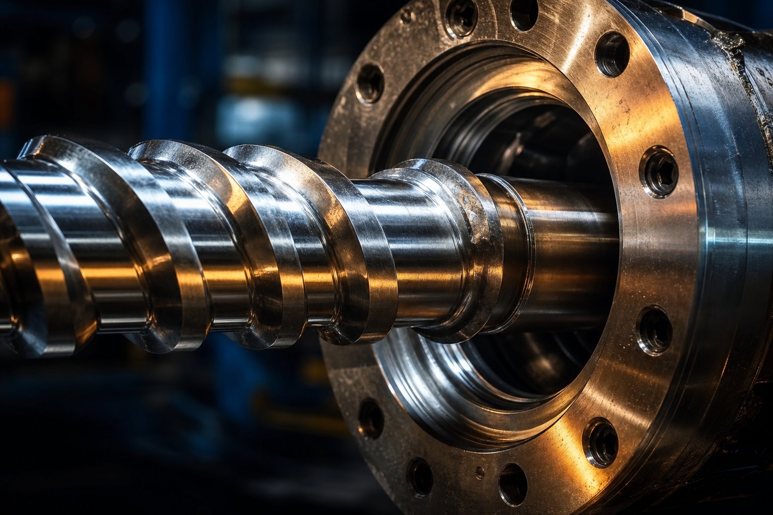
Understanding the Screw and Barrel in Plastics Processing
Your output is dropping. Cycle times are creeping up. Melt quality looks inconsistent, and you've already bumped screw speed and backpressure twice this month just to keep parts acceptable. Sound familiar? These are the early warning signs that your screw and barrel assembly is wearing out — and if you don't recognize them in time, you're headed toward unplanned downtime and costly emergency replacements.
What Is a Screw and Barrel System
A screw and barrel is the core plasticating unit in extrusion and injection molding machinery, consisting of a helical-flighted screw rotating inside a precision-bored, heated cylindrical barrel. Together, these components convey, compress, melt, mix, and pressurize polymer material into a homogeneous melt ready for shaping.
Think of it as the heart of any plastics processing line. The screw provides the mechanical energy — its rotating flights grab solid pellets from the feed throat, push them forward, and generate the shear heat that does most of the melting work. The barrel surrounds the screw, supplying supplemental heat through external heater bands while maintaining tight dimensional tolerances that make efficient plasticating possible. When extruder screws and barrels operate at original clearances, heat transfer and shear rate stay optimal. The moment wear opens those gaps, everything downstream suffers.
Why Understanding These Components Matters
Whether you run a single extruder screw barrel for film production or manage a fleet of injection molding machines, the screw barrel assembly dictates your throughput, energy consumption, melt consistency, and ultimately your profit margin. As Plastics Technology notes, original clearances between the barrel bore and flight lands are typically just 0.001 in. per side per inch of diameter — razor-thin tolerances that begin degrading the instant rotation starts.
This guide serves as a full-lifecycle reference. If you're new to processing, you'll gain foundational knowledge of component anatomy and design principles. If you're an experienced processor, you'll find advanced guidance on wear prevention, troubleshooting persistent quality issues, and making informed rebuild-versus-replace decisions. Every section ahead is built to help you extend useful life, reduce unplanned shutdowns, and get more from your plasticating equipment.
The first step toward protecting these critical components? Knowing exactly what you're looking at inside that barrel.
Screw and Barrel Anatomy Every Processor Should Know
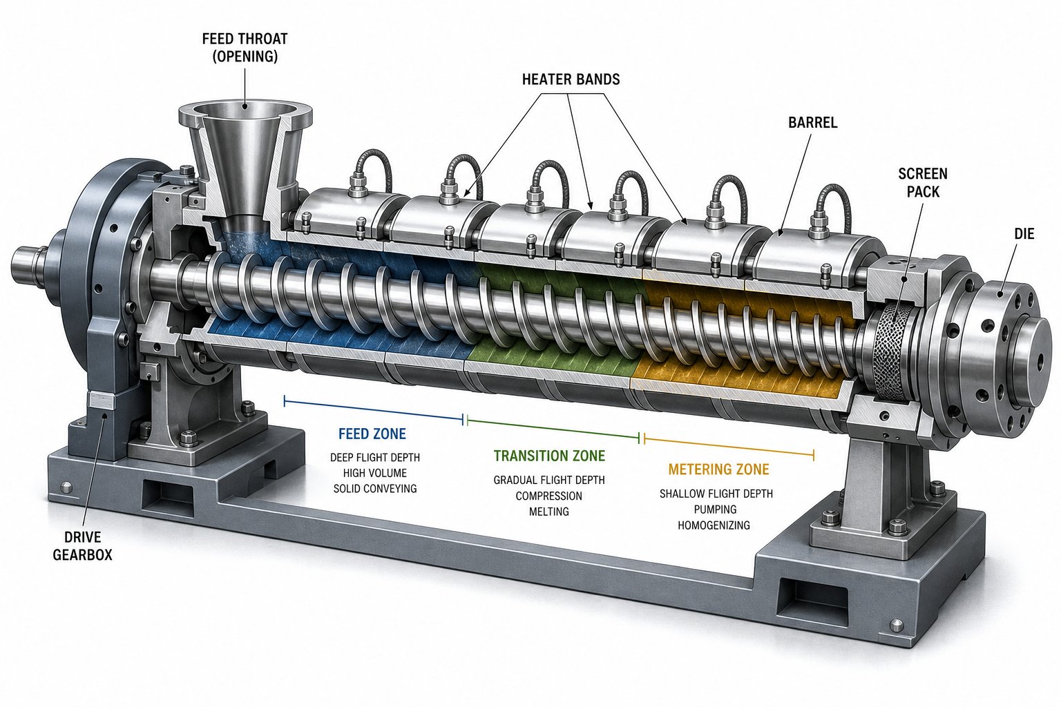
Imagine trying to diagnose engine trouble without knowing the difference between a piston and a valve. The same logic applies here. You can't pinpoint wear, specify replacements, or optimize processing parameters unless you understand each component's role in the plasticating assembly. Below is a definitive anatomy breakdown that serves as your go-to reference — whether you're inspecting an extruder barrel for wear or specifying a new extruder screw for a different resin.
Barrel Components and Their Functions
The barrel is more than a heated steel tube. It's a precision-engineered containment system designed to transfer heat, withstand internal pressure, and maintain exact bore dimensions over thousands of operating hours. Here are the critical elements:
- Barrel bore — The internal cylindrical surface machined to tight tolerances. Flight clearance depends on this bore remaining round and true.
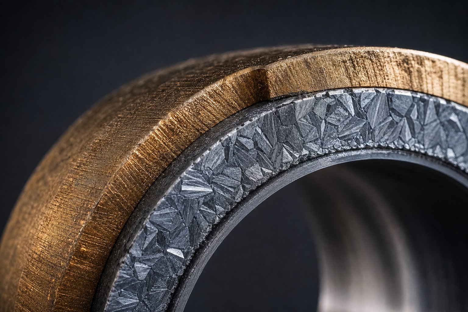
- Barrel liner (bimetallic or nitrided) — A wear-resistant inner layer that protects the base steel from abrasion and corrosion caused by filled or corrosive resins.
- Feed throat — The opening where pellets enter, typically water-cooled to prevent premature softening and bridging.
- Heater bands — External heating elements clamped around the barrel that supplement shear-generated heat and maintain zone temperatures.
- Thermocouple ports — Drilled access points that house temperature sensors, giving the controller real-time feedback for each thermal zone.
Together, these elements form what some technicians informally call the screw tube — the containment envelope that makes controlled plasticating possible.
Screw Zones and Geometry Fundamentals
The screw is where the real work happens. Its geometry determines how pellets move, melt, mix, and pressurize. Every single-screw design divides into three functional zones, each with distinct channel depths that progressively compress the material:
| Component | Location | Primary Function |
|---|---|---|
| Feed zone | Rear section (hopper end) | Accepts solid pellets and conveys them forward using deep flights and frictional drag |
| Transition (compression) zone | Middle section | Gradually reduces channel depth, compressing and shearing pellets into a melt pool |
| Metering zone | Front section (discharge end) | Delivers uniform, fully melted polymer at consistent pressure and temperature |
| Flights | Along entire screw length | Helical ridges that push material forward and create the channels between them |
| Root diameter | Core of the screw shaft | Increases from feed to metering, reducing channel depth and raising compression |
| Flight depth | Measured from root to flight tip | Controls channel volume — deeper channels carry more material at lower shear |
| Flight clearance | Gap between flight tip and barrel bore | Maintains thin polymer film for heat transfer; when worn, causes leakage flow and output loss |
Channel depth is the geometry variable that governs everything downstream. As MD Plastics notes, deep channels deliver more throughput with less shear, while shallow channels generate faster melting at higher melt temperatures. The interplay between these depths across the three zones is what processors call the compression ratio.
Understanding Compression Ratio
Here's the simplest way to think about it: compression ratio equals the flight depth in the feed zone divided by the flight depth in the metering zone. A screw with a 0.400-inch feed depth and a 0.160-inch metering depth has a compression ratio of 2.5:1.
Why does this single number matter so much? Because it dictates how aggressively the screw compresses and shears the polymer as it travels forward. A higher ratio means more mechanical energy input per unit of output — faster melting, more intense mixing, and greater heat generation through friction. A lower ratio treats the resin more gently, reducing the risk of thermal degradation in shear-sensitive materials.
Practical ranges help frame the decision:
- 1.5:1 to 2:1 — Gentle melting suited to heat-sensitive resins like PVC and certain medical-grade polymers
- 2:1 to 2.5:1 — General-purpose range covering PE, PP, PS, and ABS
- 3:1 and above — Aggressive melting for crystalline polymers and applications demanding intensive color mixing
The compression ratio for an injection molding screw typically falls between 2:1 and 3:1, while extrusion screws may run higher ratios depending on the polymer's melt energy requirement and viscosity characteristics. As Paul Murphy Plastics explains, the ratio must account for both feeding behavior and shear heating — not one or the other.
Getting the compression ratio wrong doesn't just reduce efficiency. Too much compression causes degradation, discoloration, and excessive melt temperatures. Too little leaves unmelted pellets in the output stream, contaminating parts and forcing operators to compensate with higher barrel temperatures or slower speeds. Either mistake shortens component life and drives up operating costs.
With this anatomy locked in, the natural next question becomes: how do different screw designs arrange these same elements to handle specific resins and applications?
Screw Design Types and Geometry Selection
Compression ratio, flight depth, channel geometry — they all matter. But here's the thing: two screws with identical compression ratios can produce wildly different results if their overall design architecture doesn't match the resin and application. Choosing the right plastic extruder screw means understanding the fundamental design families and knowing which one solves your specific melting, mixing, or conveying problem.
General Purpose vs Barrier Screw Designs
A general-purpose (GP) screw is the default starting point for most processors. It uses a single-flighted channel across all three zones, relying on progressive compression to melt the polymer. Simple, versatile, and cost-effective — it handles a broad range of thermoplastics acceptably. The catch? At higher screw speeds, the solid bed inside the channel tends to break apart prematurely, sending unmelted chunks into the metering zone. The result is pressure surging, inconsistent melt temperature, and visible defects in finished parts.
A barrier screw solves this with an elegant mechanical trick: a secondary flight — the barrier flight — splits the transition zone channel into a solids channel and a melt channel. Only fully melted polymer can cross the barrier clearance into the melt side, so unmelted material stays confined until it finishes melting. As independent testing has shown, this design commonly delivers 20% or more additional output with dramatically better melt uniformity compared to a GP extrusion screw of the same diameter and L/D ratio. Maddock and Spirex-style barrier designs are among the most widely specified variants.
That said, barrier screws aren't universally superior. They generate more shear heat, which makes them a poor fit for heat-sensitive polymers like PVC or POM. If your single extruder screw already melts the resin fully at current speeds, a barrier upgrade won't gain you much — and if your real issue is wear rather than design, the barrier screw is an expensive answer to the wrong question.
Mixing Elements and Distributive vs Dispersive Approaches
Some applications need more than efficient melting — they demand thorough blending of colorants, additives, or filler packages. That's where mixing elements come in, and they fall into two categories:
- Dispersive mixing — Applies high shear stress to break down agglomerates (clumped pigments, undispersed additives). Maddock-style mixers and fluted mixing sections are classic dispersive elements.
- Distributive mixing — Splits and recombines melt streams to spread already-broken-down particles evenly throughout the matrix. Pin mixing sections and pineapple-style elements excel here.
Many modern screw designs combine both types. A barrier screw with a dispersive mixing section at the tip, for example, can eliminate unmelts and deliver uniform color distribution in a single pass. Double-flighted designs offer another approach — two parallel flights improve conveying stability and reduce pressure pulsation, making them popular for precision film and sheet extrusion where output consistency is non-negotiable.
When to Specify a Vented Screw Design
Running hygroscopic resins like nylon, PET, or polycarbonate? A vented screw can eliminate the need for a separate pre-drying step. These designs include a decompression zone partway along the screw length where channel depth suddenly increases, dropping melt pressure to near-zero and allowing trapped moisture or volatiles to escape through a vent port in the barrel. The melt then recompresses in a second metering section before exiting.
Vented screws are also valuable in recycling operations where incoming feedstock carries inconsistent moisture levels. The tradeoff is a longer overall screw length (typically 30:1 L/D or higher) and a more complex processing window — if the vent zone doesn't fully decompress, polymer can flow out the vent port and create a mess.
| Design Type | Best Application | Mixing Capability | Output Characteristics | Typical Use Case |
|---|---|---|---|---|
| General Purpose (GP) | Broad range of thermoplastics at moderate speeds | Basic — no dedicated mixing section | Adequate at low-to-mid RPM; surging risk at high speed | PE, PP, PS pipe and profile extrusion |
| Barrier (Maddock/Spirex) | Output-limited lines needing melt uniformity | Good — melt separation improves homogeneity | 20%+ higher throughput with tighter melt temperature | Polyolefin film, sheet, and blow molding |
| Mixing (Dispersive/Distributive) | Color-critical or additive-heavy formulations | Excellent — targeted shear or stream splitting | Uniform dispersion at standard throughput | Masterbatch, filled compounds |
| Double-Flighted | Precision applications demanding low pulsation | Moderate — improved conveying stability | Very stable pressure and output | Optical film, medical tubing |
| Vented | Moisture-sensitive or recycled resins | Moderate — depends on secondary metering zone | Eliminates pre-drying; longer L/D required | Nylon, PET, PC, recycled flake processing |
All of these designs live in the single-screw world. Twin screw configurations operate on a fundamentally different principle. Instead of relying on frictional drag between the polymer and the barrel wall, a twin screw barrel uses two intermeshing screws that physically push material forward through positive displacement. This gives twin screws superior self-wiping capability and far more intense mixing action — making them the standard for compounding, reactive extrusion, and processing difficult feedstocks like powders or highly filled formulations. The tradeoff is higher capital cost, greater operational complexity, and elevated wear in high-shear zones.
A common specification mistake? Defaulting to a GP screw because it's cheaper when the application clearly calls for a barrier or mixing design. Another frequent error is jumping to a twin screw platform when a well-designed single extruder screw with the right mixing elements would deliver the required results at a fraction of the investment. Match the design to the problem — not to habit or budget pressure alone.
Selecting the right screw geometry is only half the equation, though. The material that geometry is made from — and the coatings protecting its surfaces — will determine how long that carefully chosen design keeps performing at spec.
Materials and Coatings That Resist Wear
A perfectly designed screw geometry won't protect you from premature failure if the underlying metallurgy can't withstand your processing environment. Glass fibers chew through soft steel. Chlorine vapors from PVC eat into unprotected surfaces. The material your extruder barrels and screws are built from — and the surface treatments layered on top — ultimately determine whether you get 18 months of service life or five years.
Base Material Options for Barrels and Screws
Every screw and barrel starts with a base alloy. The question is how much protection that base material needs based on what you're processing. Here's how the primary options compare:
| Material Type | Composition / Hardness | Best Application |
|---|---|---|
| Nitrided Steel (38CrMoAlA) | 900–1000 HV surface case | Unfilled or low-abrasive polymers (PP, PE, PS, ABS) |
| Bimetallic — Centrifugal Cast | Nickel-chromium-boron alloy with tungsten carbide (58–65 HRC) | Glass-filled (30–50%) nylons, PET, PBT |
| Powder Metallurgy (PM) Steel | Vanadium carbide rich (65–68 HRC) | Highly abrasive compounds, wood-plastic composites, ceramic fillers |
| Tungsten Carbide Overlay | 1200–1400 HV | Extreme abrasion combined with corrosive elements |
A standard nitrided extrusion barrel handles unfilled polyolefins beautifully — it offers excellent fatigue resistance, lower cost, and easier repair. But the moment glass fiber content exceeds 15%, that nitrided surface begins wearing at an accelerated rate. Industry testing shows bimetallic barrels last 3–5 times longer than nitrided alternatives in glass-filled applications.
For corrosive resins — PVC, CPVC, fluoropolymers, or anything with brominated flame retardants — different alloys are needed entirely. Hastelloy C-276 and Inconel 625 liners resist the hydrochloric and hydrofluoric acid byproducts these materials release during processing. On the screw side, Colmonoy 56 (a nickel-based alloy with boron) provides outstanding resistance to PVC degradation, while martensitic stainless steels like 440C or 17-4 PH serve well when both hardness and chemical resistance are required in an injection molding barrel.
Surface Treatments That Extend Component Life
When base metallurgy alone isn't enough — or when you want to push service life further without the cost of a full bimetallic build — surface treatments add a critical defense layer. Each targets specific failure modes:
- PVD coatings (TiN, CrN, CrON) — Deposits an extremely hard, thin film through physical vapor deposition in a vacuum chamber. Reduces friction, resists corrosion, and prevents polymer adhesion. Ideal for extrusion barrels processing corrosive polymers or applications where material sticking causes degradation and black specks. Chromium nitride (CrN) coatings are particularly effective against PVC's chlorine vapors.
- CVD coatings (Chemical Vapor Deposition) — Applies coatings at higher temperatures than PVD, producing excellent adhesion and uniform coverage even in complex geometries. Best suited for screws with intricate mixing elements where coating uniformity is difficult to achieve.
- Chrome plating — A proven, cost-effective option at 50–80 microns thickness. Effective for mildly corrosive polymers and moderate-wear applications. Limited by its tendency to crack under high localized stress.
- Tungsten carbide overlays — Applied to screw flight lands via thermal spray or laser cladding, achieving hardness levels of 1200–1400 HV. The go-to solution when abrasive fillers are destroying flight tips faster than any other surface.
- Plasma nitriding — A refined version of traditional gas nitriding that produces a harder, more uniform case with less distortion. Suitable for general-purpose protection on nitrided steel substrates.
- DLC (Diamond-Like Carbon) — The most wear-resistant coating available, with extremely low friction coefficients. Also the most expensive — reserved for high-value applications where extended life justifies the investment.
One important practical note: PVD coatings are thin enough that they won't affect screw dimensions beyond tolerance, but proper surface preparation is essential. Residues from previous nitriding treatments must be completely removed, and polishing is often required before deposition to ensure adhesion.
Matching Materials to Your Processing Environment
Here's where many processors make costly mistakes — they either over-specify materials (spending money on bimetallic extrusion barrels when nitrided steel would serve perfectly) or under-specify them (running glass-filled nylon through a standard nitrided barrel and wondering why output drops 10% every six months).
The decision logic breaks down into two questions: Is your resin abrasive, corrosive, or both?
- Abrasive fillers (glass fiber, mineral powders, ceramic particles) — Demand harder surfaces. Bimetallic barrels with centrifugal-cast liners paired with tungsten carbide flight overlays on the screw provide maximum protection. Hardness is your primary defense.
- Corrosive resins (PVC, fluoropolymers, flame-retardant compounds) — Demand chemical-resistant alloys. Nickel-based liners (Hastelloy, Inconel) and PVD coatings like CrN or CrON protect against acidic attack. Hardness alone won't help — you need corrosion barriers.
- Both abrasive and corrosive (glass-filled flame-retardant PA66, mineral-filled PVC) — The most demanding scenario. Combine a bimetallic barrel featuring tungsten carbide in a nickel-chromium-boron matrix with a screw hardfaced using Colmonoy 83. This dual approach addresses both failure mechanisms simultaneously.
An often-overlooked consideration is the hardness differential between your screw and barrel. If both components have similar hardness, metal-to-metal contact during deflection or misalignment can cause galling — adhesive wear that damages both parts simultaneously. The general rule: maintain a measurable hardness difference so one component wears preferentially and can be replaced without scrapping both.
Choosing the right metallurgy keeps your components alive longer. But even the best materials can't protect you from process conditions they weren't designed for — and the real challenge facing most processors isn't material selection in isolation. It's understanding how their specific application demands interact with every choice they make, from geometry to surface treatment to operating parameters.
Industry Applications from Plastics to Pharmaceuticals
Every resin behaves differently. Every industry imposes unique constraints. A screw extrusion system optimized for polyethylene blown film would be a disaster in a rubber tire line — and a food-grade pharmaceutical extruder demands considerations that plastics processors rarely think about. Understanding how application demands shape hardware choices is what separates processors who get years of trouble-free production from those who constantly fight wear, degradation, and quality drift.
Plastics Extrusion and Injection Molding Applications
Plastics processing spans an enormous range of product types, and each one places different demands on the screw and barrel system. On the extrusion side, the distinctions are significant:
- Film extrusion (blown and cast) — Demands exceptional melt homogeneity and tight temperature control. Even minor inconsistencies show up as gauge variation or optical defects. Barrier screws with distributive mixing elements dominate here.
- Pipe and profile extrusion — Prioritizes stable output pressure and consistent melt viscosity. General-purpose or barrier designs handle most polyolefin pipe work, while PVC profiles require corrosion-resistant metallurgy and lower compression ratios.
- Sheet extrusion — Similar to film but at higher throughputs and greater thicknesses. Double-flighted screws reduce pressure pulsation that would otherwise cause thickness banding in the finished sheet.
Injection molding screws and barrels face a fundamentally different duty cycle. Instead of continuous rotation, an injection molding screw reciprocates — it rotates to plasticize a shot, then moves forward axially to inject the melt into a mold. This reciprocating action creates unique wear patterns concentrated at the check ring and front flight lands. Application-specific considerations include:
- Thin-wall molding — Requires high injection speeds, meaning the injection molding screw must deliver extremely uniform melt with zero unmelts that could block thin flow paths.
- Thick-section molding — Longer cycle times mean extended residence time in the barrel. The injection molding barrel and screw must prevent degradation during these extended hold periods.
- Micro-molding — Uses miniature screws (sometimes under 14 mm diameter) where even microscopic wear affects shot consistency and part weight repeatability.
Rubber and Elastomer Processing Requirements
Here's where everything changes. Rubber doesn't melt — it shears, warms, and mixes, but crossing the temperature threshold triggers vulcanization (scorch), and scorched compound is irreversible scrap. As rubber processing specialists note, barrel temperatures typically stay between 80 and 120 degrees Celsius — far below thermoplastic melt temperatures — because premature cure destroys the material permanently.
This single constraint reshapes every hardware decision:
- Shallower flight channels — Lower compression ratios reduce shear-generated heat that could trigger scorch.
- Shorter L/D ratios — The compound doesn't need long melting zones; it needs controlled conveying and mixing.
- Pin barrel designs — Radial pins penetrating from the barrel wall into the screw channel provide distributive mixing without adding dangerous shear heat. Pins cut, fold, and redirect the rubber stream, dispersing carbon black and curatives uniformly.
- Aggressive cooling systems — Because frictional heat at flight clearances is what triggers scorch, barrel cooling must respond quickly to prevent thermal runaway.
Cold feed rubber extruders do all warming, mixing, and forming internally, demanding longer screws and pin barrel sections. Hot feed extruders receive pre-warmed stock from an open mill, requiring shorter, simpler geometry focused primarily on conveying and die-forming.
Food and Pharmaceutical Grade Specifications
When your extruder output goes into someone's mouth or bloodstream, material safety and hygienic design override every other consideration. FDA compliance dictates material choices, surface finishes, and assembly designs that plastics and rubber processors rarely encounter.
Key requirements for food and pharmaceutical screw and barrel systems include:
- FDA-compliant contact materials — Screws and barrels must use stainless steels (typically 304 or 316L) or food-safe coatings that won't leach into the product stream.
- Surface finish standards — Interior surfaces polished to Ra 0.4 micrometers or better to eliminate microscopic crevices where bacteria or product residue could harbor.
- Sanitary design principles — No dead spots, no undercuts, no areas where material can stagnate and degrade. Every geometry decision must consider cleanability.
- CIP (Clean-in-Place) compatibility — The assembly must tolerate aggressive cleaning chemicals and thermal cycling without corrosion or dimensional change.
- Full traceability — Material certifications, heat treatment records, and dimensional inspection documentation must accompany every component.
Pharmaceutical extruders — particularly for hot-melt extrusion of drug delivery systems — add even more constraints. Twin screw configurations dominate here because their self-wiping action minimizes product hangup, and modular screw elements allow precise control over mixing intensity and residence time distribution.
| Industry | Key Screw Features | Barrel Requirements | Critical Considerations |
|---|---|---|---|
| Plastics — Extrusion | Barrier or GP design; mixing elements for color-critical work; 24:1 to 34:1 L/D | Bimetallic or nitrided based on filler content; multi-zone heating | Melt homogeneity, output stability, energy efficiency |
| Plastics — Injection Molding | GP or barrier with check ring; 20:1 to 24:1 L/D; reciprocating duty | Wear-resistant bore at front end; precise temperature zoning | Shot-to-shot consistency, residence time management, check ring wear |
| Rubber / Elastomers | Shallow channels; low compression; pin mixing sections; short L/D | Pin barrel construction; aggressive cooling; bimetallic for filled compounds | Scorch prevention, temperature control, filler dispersion quality |
| Food Processing | Stainless steel construction; no dead spots; polished surfaces; sanitary geometry | 316L stainless; Ra 0.4 um finish; CIP-compatible; no crevice corrosion points | FDA compliance, cleanability, material traceability, bacterial harbor elimination |
| Pharmaceutical | Modular twin screw elements; precise residence time control; self-wiping profiles | Stainless construction; GMP documentation; full validation packages | Drug content uniformity, API stability, complete batch traceability |
Notice the pattern across industries: every application starts with the same fundamental components — flights, channels, a heated bore — but the constraints each industry imposes reshape those components into dramatically different solutions. Rubber demands gentleness. Pharmaceuticals demand traceability. Filled plastics demand hardness. And in every case, the wrong specification doesn't just reduce efficiency — it creates failures that cascade through product quality, regulatory compliance, and ultimately profitability.
Regardless of industry, though, every one of these systems shares a common enemy: wear. The mechanisms that destroy screws and barrels operate the same way whether you're processing tire-tread rubber or medical-grade polycarbonate — they just attack different surfaces at different rates depending on the material flowing through.
Wear Mechanisms and How to Prevent Premature Failure
Wear doesn't announce itself with a catastrophic bang. It creeps in quietly — a fraction of a thousandth of an inch at a time — until one morning your operator notices output is down 10%, discharge temperatures are climbing, and energy bills keep getting higher. By then, the damage is well advanced. Understanding how your barrel and screw wear, and why specific processing conditions accelerate that wear, gives you the ability to intervene before a minor tolerance change becomes a production crisis.
Three distinct mechanisms drive virtually all component degradation. Each one attacks differently, leaves different evidence behind, and demands different prevention strategies.
Abrasive Wear Causes and Prevention
This is the most common killer of extruder screws and barrels. Abrasive wear occurs when hard particles in the polymer stream — glass fibers, mineral fillers like calcium carbonate and talc, titanium dioxide pigments, ceramic microspheres — physically erode metal surfaces through repeated contact. Imagine fine sandpaper spinning inside a precision bore thousands of hours per year. That's essentially what's happening.
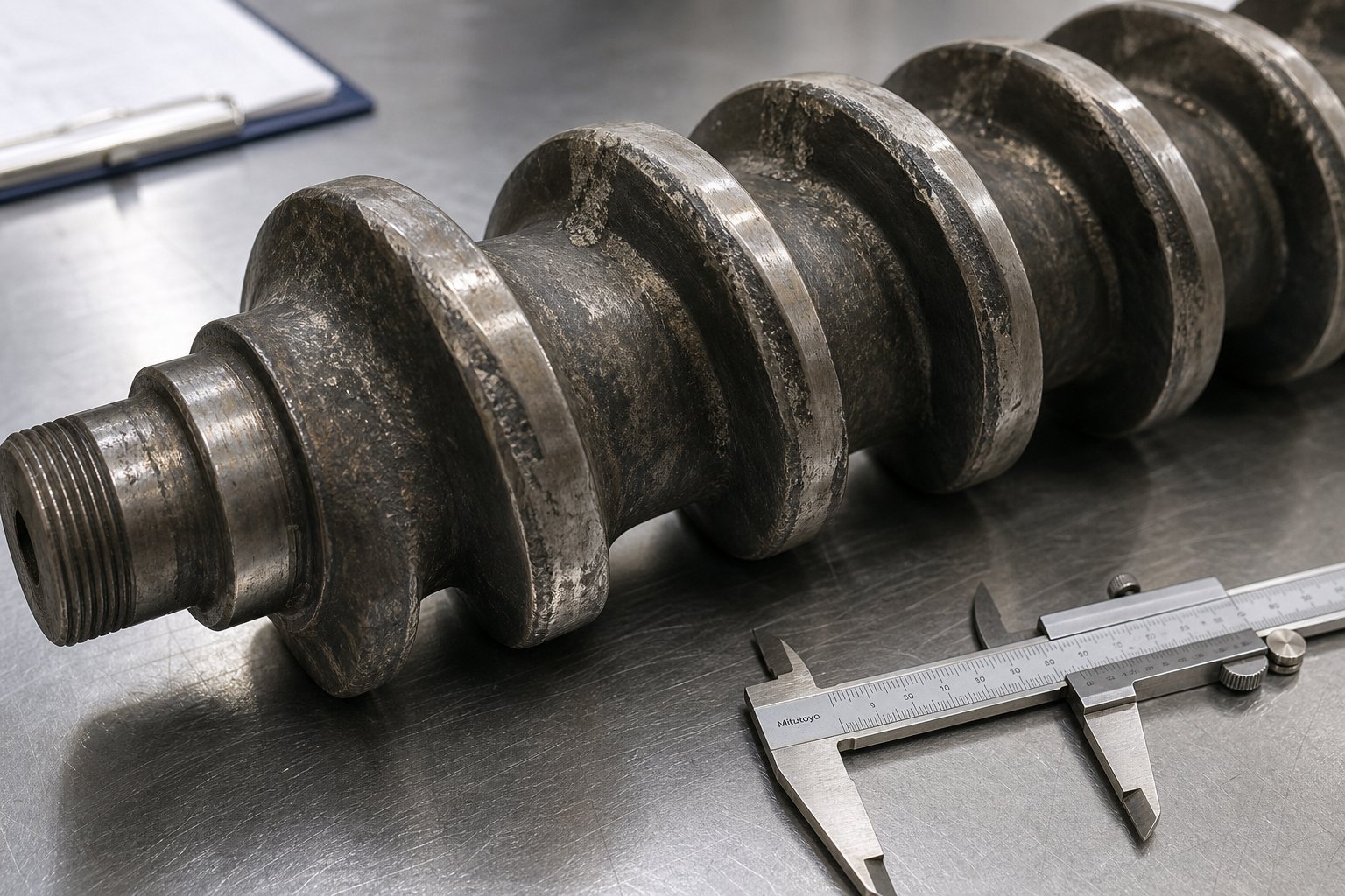
The damage is predictable in its pattern. Flight tips lose their sharp, machined edges and become rounded and polished. The barrel bore develops elongated grooves or uniform diameter increases in zones where solids concentration is highest — typically the transition zone and the entry to mixing elements. As Plastics Technology reports, solids can momentarily jam at the end of the melting section or at mixer entries, creating large lateral forces that push the screw against the barrel wall and accelerate localized wear far beyond normal rates.
The severity depends on three interacting factors:
- Filler hardness and concentration — Glass fibers (Mohs 6.5) erode surfaces far faster than calcium carbonate (Mohs 3). A 40% glass-filled nylon is exponentially more destructive than a 20% talc-filled polypropylene.
- Screw speed and throughput — Higher speeds mean more particle-to-metal impacts per unit of time. Doubling speed doesn't double wear — it can triple or quadruple it depending on the filler package.
- Metallurgy mismatch — Running abrasive compounds through nitrided steel screws and barrels instead of bimetallic or tungsten carbide-protected components dramatically shortens service life.
Prevention starts with material selection — bimetallic barrel liners and tungsten carbide flight overlays are your primary defense for filled resins. But it also includes process discipline: avoid running screws at unnecessarily high speeds, ensure uniform pellet feeding to prevent pressure spikes, and monitor filler loading consistency in your incoming raw materials.
Adhesive and Corrosive Wear Mechanisms
Adhesive wear happens when metal touches metal — and in a system where a rotating screw spins inside a stationary barrel with only a thin polymer film separating them, it doesn't take much to close that gap. Barrel misalignment, screw deflection under process loads, thermal warping from faulty heater bands, or even foundation settling on older machines can all force flight tips into direct contact with the barrel bore.
The telltale signs are distinctive. You'll notice score marks — long scratches running axially along the barrel wall — and flattened or galled areas on flight lands. Twin screw systems are especially vulnerable because their screws are rigidly fixed at the gearbox end and supported by molten resin along the barrel length. Between production runs, if screws rotate without polymer present to maintain that supporting film, adhesive wear accelerates rapidly.
Corrosive wear, by contrast, is a chemical attack. Certain polymers release acidic byproducts during processing — PVC generates hydrochloric acid, fluoropolymers produce hydrofluoric acid, and flame-retardant compounds release corrosive halogen gases. Hygroscopic materials that enter the barrel with residual moisture can also generate acidic degradation products at processing temperatures. The resulting damage appears as pitting, cratering, and a roughened surface texture that's clearly different from the smooth erosion pattern of abrasion.
What makes corrosive wear particularly insidious is that it attacks the entire surface simultaneously, not just high-contact areas. The protective oxide layer or nitrided case dissolves uniformly, leaving the softer base metal exposed to both corrosion and accelerated abrasive attack. The two mechanisms feed each other — corrosion roughens the surface, the roughened surface traps abrasive particles, and wear rates compound.
Prevention differs fundamentally from abrasive wear strategies. Hardness alone won't save you. Corrosion-resistant alloys — nickel-based liners like Hastelloy or Inconel for barrels, and chromium-rich hardfacings like Colmonoy 56 for screws — are essential. PVD coatings, particularly chromium nitride (CrN), add an additional chemical barrier. Equally important: keep resin dry, maintain proper melt temperatures to avoid thermal degradation, and ensure adequate venting to evacuate corrosive gases before they attack metal surfaces.
Monitoring Wear and Establishing Replacement Criteria
Here's the critical question every processor faces: how much wear is too much? The answer isn't a single number — it depends on the process tolerance and the economics of your specific operation.
First, understand what happens as flight clearance increases beyond original specifications. The standard guideline sets new flight clearance at the nominal screw diameter divided by 1000 per side. For a 3.5-inch extruder, that's roughly 0.004 inches per side. As wear opens this gap, a cascade of performance problems begins:
- Output drops — Material leaks backward over worn flight tips instead of moving forward, reducing the effective pumping rate. To maintain throughput, the operator increases screw speed.
- Discharge temperature rises — Higher screw speeds combined with increased film thickness at the barrel wall (from the wider clearance) reduce heat-transfer efficiency, pushing melt temperatures up. Data from a 100 mm screw running 1 MI polyethylene at 150 kg/hr showed discharge temperatures climbing from 236 degrees Celsius with new clearances to nearly 246 degrees Celsius at 0.016-inch clearance — enough to make blown film production impossible without reducing throughput by approximately 13%.
- Energy consumption increases — The motor works harder to compensate for lost conveying efficiency, driving up specific energy consumption (kWh/kg).
- Melt quality degrades — Wider clearances allow partially melted material to bypass the compression zone, creating temperature and viscosity variations in the melt stream.
Catching these changes before they become production-limiting requires a structured monitoring protocol — not occasional spot checks when something already seems wrong. Here's a practical approach:
- Record baseline dimensions at installation — Measure and document the barrel bore diameter at multiple points along its length and the screw flight outside diameter at every flight. These are your reference values for all future comparisons.
- Schedule bore measurements at regular intervals — Use a telescoping bore gauge or dedicated wear gauge to measure barrel ID during planned shutdowns. Quarterly checks are a reasonable starting point for moderate-wear applications; monthly for highly abrasive compounds.
- Track specific rate continuously — Specific rate (output divided by screw speed) is the single most sensitive early indicator of wear in screws and barrels. Log it weekly. A downward trend means the screw is losing pumping efficiency.
- Monitor discharge temperature at constant rate — If you're holding the same throughput but discharge temperatures are creeping upward, flight clearance has increased enough to affect heat transfer.
- Inspect melt quality indicators — Watch for increased gel counts, visible unmelts, color streaking, or rising reject rates. These are downstream symptoms of upstream clearance loss.
- Measure screw flight OD during every pull — Whenever the screw is removed for cleaning or inspection, use a micrometer with a parallel test bar spanning two flights, as Adams Engineers recommends. Compare values against baseline and previous measurements to build a wear profile over time.
- Compare cumulative data against replacement criteria — Use the SPI Dimensional Guidelines as a starting reference for maximum acceptable wear.
Replacement criteria should reflect the criticality of your application. Some common benchmarks from industry practice:
| Application Criticality | Max Acceptable Flight Clearance | Rationale |
|---|---|---|
| Critical (medical, optical) | 2x original clearance | Extremely tight melt quality and shot consistency requirements |
| Standard (packaging, general parts) | 3x to 4x original clearance | Balances performance degradation against replacement cost |
| Non-critical (corrugated pipe, lumber) | 5x+ original clearance | Product tolerates wide process variation; maximize component life |
Keep in mind that a barrel with an iron-based bimetallic liner typically lasts about three times the service life of a screw. So when you pull a worn screw, always measure the barrel bore as well — but don't assume it needs replacement on the same schedule. And here's a rule worth remembering: a screw should never be refurbished more than three times, because repeated welding of hardfacing onto the base metal degrades the substrate and increases the risk of delamination.
The smartest processors don't wait for symptoms to appear. They keep a spare screw in storage so that when measurements hit the reject threshold, a fresh component goes in immediately — minimizing downtime while the worn screw gets refurbished or replaced. That swap-and-rebuild strategy, though, raises its own question: at what point does refurbishing a worn component stop making economic sense compared to buying new?
Troubleshooting Common Screw and Barrel Problems
Monitoring tools tell you that something is wrong. Troubleshooting tells you what and why. The frustrating reality on most production floors is that operators adjust process settings — bump temperatures, increase backpressure, tweak screw speed — long before anyone considers the hardware itself as the root cause. Yet many persistent quality and output problems trace directly back to a worn or incorrectly specified screw plastic extruder assembly hiding in plain sight beneath layers of compensating adjustments.
Here's a symptom-first guide to diagnosing the most common issues and determining whether you're dealing with a process problem or a hardware problem.
Diagnosing Output Inconsistency and Surging
Output surging — that rhythmic cycling of melt pressure, motor current, or extrudate dimensions — is among the most disruptive problems a processor can face. It drives up scrap rates, forces slower line speeds, and makes dimensional control nearly impossible. The tricky part? Surging has multiple potential root causes, and each one demands a different fix.
The most common culprit in smooth-bore extruders is improper temperature in the solids conveying section. As extrusion expert Mark Spalding explains, solids conveying depends on a balance between forwarding forces at the barrel wall and retarding forces at the screw root. When temperatures fall outside the optimal window, this balance collapses cyclically — the screw alternates between gripping and starving, producing pressure oscillations that propagate all the way to the die.
In one documented case, an 8-inch two-stage extruder running polystyrene began surging after 400 minutes of stable operation. The specific rate — output divided by screw speed — swung wildly between 14 and 23 kg/(hr·rpm). The root cause? Inadequate screw cooling. The cooling hole in the screw was 3 diameters too short to reach the end of the solids conveying section, allowing the screw surface to overheat and lose its grip on incoming pellets. Extending the cooling bore and adding a dedicated water pump permanently eliminated the surging.
A second cause of surging is a worn metering zone. When flight clearance opens up in the final screw section, leakage flow over the flights fluctuates with minor pressure changes, creating cyclic output variation that looks identical to feed-related surging on a pressure chart. The difference? Feed-related surging responds to temperature adjustments at the extruder feed barrel and first zone, while metering-zone wear surging does not — it only gets worse as the operator increases speed to compensate.
Addressing Melt Quality and Material Degradation Issues
Poor melt quality shows up as visible unmelts, temperature non-uniformity, color streaking, or inconsistent viscosity in the extrudate. When an injection screw delivers a non-uniform melt, you'll see short shots, surface defects, weld-line weakness, and dimensional variation from shot to shot.
The most frequent hardware-related cause is insufficient compression — either the screw design never had adequate compression ratio for the resin, or wear on the flight lands has effectively reduced the working compression by increasing leakage flow. Material that should be fully melted and homogenized by the end of the transition zone arrives at the metering section partially solid, and no amount of barrel temperature increase can compensate for the lost mechanical energy input.
Black specks deserve special attention because they're a universal customer complaint that often gets blamed on contamination when the real source is the barrel extruder hardware itself. Root wear creates pockets and areas for material to hang up and degrade, eventually releasing carbonized particles into the melt stream. Worn flight lands lose their sharp edges, creating ledges where thin films of polymer stagnate, oxidize, and periodically break free as black specks. In severe cases, the sides of the flights become washed out, leaving rough surfaces that compound the hangup problem.
Material degradation from excessive residence time is another hardware-triggered issue. An oversized barrel for the actual throughput being run means polymer sits at melt temperature far longer than necessary. Similarly, dead spots in worn mixing elements or damaged check rings trap material that degrades thermally and then contaminates subsequent shots.
Solving Feed Problems and Conveying Failures
When your extruder feed barrel zone can't consistently deliver pellets to the screw, nothing downstream can compensate. Feed problems manifest as erratic motor load, fluctuating melt pressure, and visible output variation — sometimes mild enough to be mistaken for normal process noise, sometimes severe enough to shut down the line entirely.
The primary diagnostic checkpoint is simple: touch the feed casing. It should feel warm — not hot. A hot feed throat means the cooling water channels have occluded with mineral deposits or the water flow rate has dropped, allowing conducted heat from the first barrel zone to soften pellets prematurely. Softened pellets agglomerate, bridge across the feed opening, and starve the screw. Flushing the feed casing cooling channels with an acidic descaling solution and installing a dedicated cooling water pump often resolves chronic feed instability that had been incorrectly attributed to resin bulk density variation.
Bridging can also occur from mechanical causes — a hopper design that allows material to arch, a feed throat geometry that doesn't match the pellet shape, or a screw root temperature that's too high in the first few turns. For hygroscopic materials processed on twin screw systems, moisture-induced clumping at the feed throat is a leading cause of erratic conveying that's entirely preventable with proper pre-drying and climate-controlled storage.
Below is a quick-reference troubleshooting table covering the most common symptoms, their likely hardware origins, and the diagnostic steps that separate process issues from component failures:
| Symptom | Likely Cause | Diagnostic Step | Solution |
|---|---|---|---|
| Cyclic output surging (rhythmic pressure oscillation) | Hot screw in feed section; occluded feed casing cooling; worn metering zone flights | Check feed casing temperature by touch; measure screw cooling water outlet temperature and flow; compare specific rate to baseline | Restore feed casing cooling; extend screw cooling bore; replace screw if metering zone clearance exceeds 3-4x original |
| Gradual output loss at constant screw speed | Progressive flight wear increasing leakage flow | Measure screw flight OD and barrel bore; calculate current clearance vs. original spec | Replace or rebuild screw; inspect barrel and replace if bore is out of round |
| Rising discharge temperature at constant throughput | Worn flight clearance forcing higher RPM; degraded barrel heater zone causing localized overheating | Log specific rate trend; check heater band continuity; measure barrel zone temperatures with handheld probe | Address worn components; replace failed heaters; recalibrate thermocouples |
| Black specks in extrudate or molded parts | Degraded material in worn root pockets; hangup points at damaged flight edges; carbonized residue in check ring (injection) | Pull screw and inspect root surfaces for pitting and material buildup; inspect check ring sealing surfaces | Rebuild or replace screw; polish or replace check ring; implement regular purging protocol |
| Visible unmelts or gels in output | Insufficient compression from worn transition zone; barrier flight wear reducing melt separation; wrong screw design for resin | Examine extrudate cross-section for solid particles; measure transition zone flight depths vs. original drawing | Replace screw with correct compression ratio; upgrade to barrier design if GP screw can't fully melt at required rate |
| Erratic motor current and starving | Feed throat overheating; material bridging in hopper; worn feed section flights reducing grip | Touch-check feed casing; observe pellet flow into feed throat; verify cooling water flow rate | Flush cooling channels; install agitator or vibratory insert in hopper; increase feed section flight depth on replacement screw |
| Increasing energy consumption (kWh/kg) | Worn flights requiring higher RPM to maintain rate; increased frictional drag from roughened surfaces | Calculate specific energy over time; compare current kWh/kg to baseline at same output rate | Schedule screw replacement when energy penalty exceeds 15-20% above baseline |
Notice a pattern in this table? Nearly every symptom listed gets misdiagnosed at least once as a process control issue before anyone looks at the hardware. Operators adjust temperatures, tweak speeds, change backpressure — all valid tuning moves that mask the underlying component deterioration. The adjustments work for a while, buying weeks or months of marginally acceptable production. But each compensating change pushes the process further from its design window, narrowing the operating envelope until one more small shift in ambient conditions or resin lot variation pushes the line over the edge into uncontrollable scrap.
The lesson is straightforward: when troubleshooting reveals that your process window has narrowed significantly from where it started, stop adjusting settings and start measuring hardware. Pull the screw. Gauge the bore. Compare dimensions to original drawings. The numbers don't lie — and they'll tell you definitively whether you're dealing with a tuning problem or a component that's reached end of life.
That measurement, of course, opens a new decision: is the worn component worth rebuilding, or has it reached the point where replacement makes better economic sense?
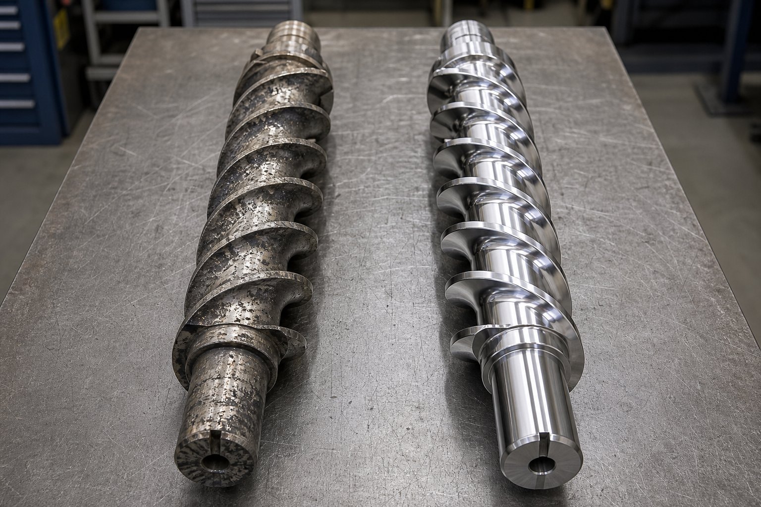
Rebuild or Replace Your Screw and Barrel
You've pulled the screw, gauged the bore, and confirmed the numbers — your components are worn beyond your operating threshold. The immediate question isn't if you need to act, but how. Do you rebuild the existing hardware and get it back into service, or invest in entirely new components? This is one of the highest-stakes maintenance decisions in plastics processing, and getting it wrong costs you either unnecessary capital expenditure or repeated downtime from a rebuild that doesn't last.
The right answer depends on the severity of wear, the economics of your specific situation, and whether you want to simply restore original performance or upgrade to a better design simultaneously.
When Rebuilding Makes Economic Sense
Rebuilding a worn screw involves restoring the original geometry through a sequence of precision repair operations. The standard professional approach includes stripping any existing surface treatment, inspecting the base metal for cracks or fatigue, welding hardfacing material onto worn flight lands, grinding the screw back to original diameters, and applying a fresh protective coating — whether that's re-chroming, re-nitriding, or a new hardfacing overlay. For barrels, rebuilding means reboring the inner diameter to a new oversize dimension and either re-nitriding or installing a new bimetallic sleeve in the worn section.
A rebuild makes strong economic sense when several conditions align:
- Wear is moderate, not catastrophic — Flight land wear that hasn't reached the screw root, and barrel bore enlargement that's still within machinable tolerance. Industry guidelines suggest that wear depth beyond 0.3-0.5 mm (depending on screw diameter) pushes past the rebuild threshold.
- Base metal integrity is sound — No cracks, no bending, no structural fatigue. The decision rests on honest inspection — which is why stripping the old surface treatment and measuring comes before committing to repair.
- The screw hasn't been rebuilt too many times already — Each rebuild consumes base material and introduces heat-affected zones from welding. Conservative practice limits rebuilds to 2-3 cycles for most screws, though some shops report 4-5 successful rebuilds when wear was caught early and repairs were minimal each time.
- The existing design is still correct for your application — If the screw geometry already matches your resin and process requirements, restoring it to original spec makes perfect sense. Rebuilding a design that was wrong from the start just gives you a like-new version of the wrong answer.
The cost advantage is significant. A professional rebuild with re-chroming or hardfacing typically runs 50-75% of the cost of a new screw, and turnaround times of 4-5 weeks are typical from specialist shops. For processors managing tight budgets on older equipment — say a davis-standard extruder that's still mechanically solid but needs fresh plasticating components — rebuilding preserves capital while restoring productive capacity.
When Full Replacement Is the Better Investment
Rebuilding has limits. Beyond a certain point, the economics flip decisively toward new components, and pushing further rebuilds onto a deteriorating substrate creates reliability risks that outweigh the savings.
Replace rather than rebuild when:
- Output loss exceeds 20% — At this level of performance degradation, the screw and barrel are severely worn and a rebuild may not fully restore original pumping efficiency.
- Repair cost approaches 50-70% of new component cost — When the cost gap narrows this far, the additional lifespan and performance guarantee of new hardware makes replacement the smarter allocation of capital.
- The bimetallic layer is completely consumed — Once a bimetallic barrel liner is worn through to base steel, re-sleeving the full length is often more expensive than a new barrel entirely. This is especially true for extruder barrels, which are longer and thinner-walled than injection barrels, making full-length re-sleeving impractical.
- Cracks, deformation, or deep corrosion pitting are present — These are structural integrity issues that welding and grinding cannot reliably fix. The risk of in-service failure far outweighs any cost savings from attempted repair.
- You want to upgrade the design — Replacement is your opportunity to move from a general-purpose screw to a barrier design, upgrade metallurgy for a new resin, or change compression ratio based on lessons learned from the previous component's performance.
- Processing demands have changed — If you've switched materials, increased throughput targets, or tightened quality requirements since the original component was specified, rebuilding to old specs gives you back a part that no longer fits the job.
There's also a machine-age consideration. If you're evaluating used extruders — perhaps browsing listings for a used twin screw extruder for sale or a davis standard extruder for sale — the screw and barrel condition should be your primary inspection focus. Used single screw extruders with recently replaced plasticating components can offer excellent value, while units with heavily worn hardware need immediate investment that erodes the purchase savings. Knowing the rebuild-vs-replace framework helps you accurately assess total acquisition cost on any used equipment.
Cost and Downtime Comparison Framework
The table below distills the rebuild-versus-replace decision into a structured comparison. Use it as a starting framework, then adjust based on your specific cost quotes, production schedule constraints, and performance requirements.
| Factor | Rebuild | Replace |
|---|---|---|
| Upfront Cost | 50-75% of new component cost | Full new component cost (higher capital outlay) |
| Expected Lifespan | 60-80% of original service life; diminishes with each successive rebuild | 100% of rated service life with full manufacturer warranty |
| Downtime Required | 4-5 weeks typical turnaround (mitigated if spare screw is available) | 2-8 weeks depending on manufacturer lead time and custom specifications |
| Performance Level | Restored to near-original spec; cannot exceed original design capability | Full original performance; opportunity to exceed via design upgrade |
| Design Flexibility | Limited to original geometry — cannot change compression ratio, add mixing elements, or alter flight configuration | Complete freedom to re-specify geometry, materials, and coatings for current needs |
| Risk Level | Moderate — depends on rebuild quality and remaining substrate integrity | Low — new metallurgy with full dimensional certification |
| Best Scenario | Moderate wear caught early; sound base metal; existing design still matches application; budget-constrained operation | Severe wear or structural damage; design upgrade needed; high-value production where reliability is paramount |
A few practical principles make this decision clearer in real-world situations:
- The "three-rebuild rule" — Most industry specialists agree that a screw should not be rebuilt more than three times. Beyond this point, cumulative heat-affected zones from welding compromise the substrate, and the risk of hardfacing delamination during processing rises substantially.
- Always measure the barrel when replacing the screw — A new screw installed into a worn barrel will wear prematurely because the increased clearance allows greater lateral movement and accelerated flight-tip contact. Barrel lifespan typically runs about three times longer than screw lifespan, so they won't always need simultaneous replacement — but they must always be measured simultaneously.
- Factor in opportunity cost — The cheapest rebuild in the world is expensive if it fails six months later and forces an unplanned shutdown during peak production season. Weigh the reliability difference against the cost difference, not just the invoice totals.
- Consider lead time strategy — Processors who maintain a spare screw can send worn units out for evaluation without production pressure. This eliminates the rushed decision-making that often pushes toward whichever option ships fastest rather than whichever option is actually optimal.
Sourcing custom or replacement screw and barrel solutions from manufacturers like NANHAIYA — who specialize in both OEM-equivalent replacements and design upgrades for extrusion and injection molding equipment — can significantly reduce lead times while providing engineering consultation on the rebuild-vs-replace question. Their technical teams evaluate worn component measurements, assess remaining substrate viability, and recommend whether restoration or a new build better serves your production goals and budget constraints.
Whether you rebuild or replace, the component that goes back into your machine needs to be the right component — matched to your current resin, your current throughput targets, and your current quality demands. That matching process is itself a discipline, and getting it right from the start prevents you from arriving back at this same decision point prematurely.
Selecting the Right Extruder Screw and Barrel for Your Process
Knowing when to rebuild or replace only solves half the problem. The harder question — and the one that determines whether you'll be back in this same position in 12 months or five years — is specifying the correct component for what you're actually running today. Not what you ran three years ago when the original was installed. Not what the machine builder assumed you'd process. What's flowing through your screw extruder right now, at the throughput you need, with the quality your customers demand.
Too many processors default to ordering "same as before" without questioning whether "before" was ever optimized in the first place. The selection process below transforms that passive habit into an active decision framework you can apply to any extrusion or injection molding platform.
Selection Criteria for Extrusion Applications
Extrusion lines run continuously — often 24/7 for weeks at a stretch. That means every inefficiency in your plastic extrusion screw compounds over thousands of operating hours. A screw that's 5% less efficient than optimal doesn't just cost you 5% in output; it costs you 5% in energy, generates excess heat that degrades product quality, and accelerates wear that shortens component life.
For extrusion, your selection priorities shift depending on the product type. Film and sheet lines demand melt homogeneity above all else — temperature variations of even 2-3 degrees Celsius show up as gauge bands or optical defects. Pipe and profile lines prioritize stable pressure and consistent viscosity. Compounding operations on twin screw and barrel systems need maximum mixing intensity with precise residence time control.
Regardless of product type, the resin and filler package dictates metallurgy. Running unfilled polyolefins? Nitrided steel serves perfectly at lower cost. Processing 30% glass-filled PA6? You need bimetallic barrels and hardfaced flights — anything less will wear out in months rather than years.
Selection Criteria for Injection Molding Applications
Injection molding adds reciprocating duty, shot-to-shot consistency requirements, and residence time management to the equation. Your extruder screw and barrel must deliver a perfectly homogeneous melt in precisely repeatable volumes — cycle after cycle, shift after shift.
Thin-wall packaging demands aggressive melting with zero unmelts. Thick-section automotive parts need gentle plasticating that avoids degradation during long cycles. Multi-material operations running frequent color or resin changes benefit from designs that minimize holdup volume and purge quickly. Each scenario points toward different compression ratios, mixing element types, and check ring configurations.
Working with Manufacturers for Custom Solutions
Here's the step-by-step process that transforms all of this guidance into a concrete specification:
- Define your resin and filler package completely — Include base polymer, filler type and loading percentage, colorant system, and any additives. A 30% glass-filled nylon with 2% carbon black demands entirely different hardware than unfilled natural nylon.
- Establish output and quality targets — Specify your required throughput in kg/hr, acceptable melt temperature range, maximum allowable pressure variation, and critical quality metrics (gel counts, dimensional tolerances, color uniformity).
- Select screw geometry based on melting and mixing needs — Match design type (GP, barrier, mixing, vented) to your resin's melting behavior and your quality requirements. Use the comparison framework from earlier sections as your guide.
- Specify barrel material and surface treatments — Match metallurgy to your wear environment. Abrasive fillers demand bimetallic construction; corrosive resins require nickel-based alloys; unfilled commodity polymers run well on nitrided steel.
- Validate with manufacturer engineering support — Share your complete specification with a manufacturer who can verify geometry calculations, recommend material upgrades based on field experience with similar applications, and flag potential issues before metal is cut.
That final step is where many processors leave value on the table. Off-the-shelf components work for generic applications, but the moment your processing involves engineered resins, aggressive fillers, tight tolerances, or high-output demands, custom engineering consultation pays for itself many times over through reduced scrap, longer component life, and optimized energy consumption.
Partnering with a specialized manufacturer like NANHAIYA — who serves plastic processors, equipment manufacturers, and maintenance teams with custom and replacement screw and barrel solutions — streamlines this entire specification process. Their engineering teams work directly with processors to evaluate application requirements, recommend geometry and metallurgy combinations proven in similar environments, and deliver both single and twin screw and barrel configurations across extrusion and injection molding platforms. Whether you need an OEM-equivalent replacement built to original drawings or a design upgrade that solves a persistent processing problem, direct manufacturer consultation eliminates the guesswork that leads to premature wear and repeated replacement cycles.
The bottom line? Every hour you spend on proper selection saves weeks of unplanned downtime later. Define your requirements clearly, match hardware to your actual process — not your assumptions — and lean on engineering expertise when the application demands more than a catalog part can deliver. Your screw and barrel are the heart of your operation. Specify them with the same precision you'd demand from any other critical production investment.
Frequently Asked Questions About Screw and Barrel Systems
1. How do I know when my screw and barrel needs replacing?
Key indicators include a declining specific rate (output divided by screw speed), rising discharge temperatures at constant throughput, increasing energy consumption per kilogram processed, and visible quality issues like black specks or unmelts. Measure flight clearance during scheduled shutdowns — when clearance reaches 3-4 times the original specification for standard applications, replacement or rebuild is warranted. Processors running critical medical or optical parts should act at 2x original clearance. Specialized manufacturers like NANHAIYA (nhyscrews.com/products) can evaluate worn component measurements and recommend whether restoration or new fabrication best fits your production goals.
2. What is the difference between a single screw and twin screw barrel system?
A single screw system relies on frictional drag between the polymer and barrel wall to convey material forward, making it simpler and more cost-effective for standard plasticating tasks. A twin screw barrel system uses two intermeshing screws that physically push material through positive displacement, delivering superior self-wiping capability and far more intense mixing action. Twin screws excel at compounding, reactive extrusion, and processing difficult feedstocks like powders or highly filled formulations, while single screws handle most standard extrusion and injection molding applications efficiently at lower capital cost.
3. What compression ratio should I use for my extruder screw?
Compression ratio — feed zone flight depth divided by metering zone flight depth — varies by resin type. Heat-sensitive polymers like PVC require gentle ratios of 1.5:1 to 2:1. General-purpose resins including PE, PP, PS, and ABS perform well at 2:1 to 2.5:1. Crystalline polymers and color-intensive applications may need 3:1 or higher for thorough melting and mixing. Selecting too high a ratio causes degradation and excessive melt temperatures, while too low a ratio leaves unmelted pellets in the output stream. Always match the ratio to both the polymer's melt energy requirement and its shear sensitivity.
4. Should I rebuild or replace a worn screw and barrel?
Rebuild when wear is moderate (less than 0.3-0.5 mm depth), base metal integrity is sound with no cracks or deformation, the component has been rebuilt fewer than three times previously, and the existing design still matches your application. A rebuild typically costs 50-75% of new component pricing. Replace when output loss exceeds 20%, repair cost approaches 50-70% of new pricing, the bimetallic layer is consumed through to base steel, or you want to upgrade geometry or metallurgy for changed processing requirements. Always measure the barrel bore when replacing a screw to ensure the new component installs into acceptable tolerances.
5. What barrel and screw materials work best for glass-filled resins?
Glass-filled polymers are highly abrasive and demand hardness-focused material solutions. For barrels, bimetallic centrifugal-cast liners containing tungsten carbide in a nickel-chromium-boron matrix provide 3-5 times the service life of standard nitrided steel. For screws, tungsten carbide overlays applied to flight lands via thermal spray or laser cladding achieve hardness levels of 1200-1400 HV, protecting the surfaces that experience the most direct particle contact. When glass content exceeds 30%, powder metallurgy steels rich in vanadium carbide offer the highest available abrasion resistance for the most demanding applications.
Written by
Nanhaiya Technical Team
Zhoushan Nanhaiya Plastic Machinery Co., Ltd.
The Nanhaiya technical team supports screw and barrel manufacturing projects through application review, technical communication, custom manufacturing coordination, and production and quality control.
Discuss Your Application
Related Articles
More insights on screw barrel technology and plastics processing.

What Nobody Tells You About Screw Barrel For Plastic Machine Design
Oct 10, 2026
Learn how screw barrel for plastic machine design affects melt quality, throughput, and wear life. Covers geometry, resin matching, troubleshooting, and sourcing.
Read Article
Single Screw Extruder for Sheet: Stop Guessing, Start Specifying
Oct 9, 2026
Learn how to specify a single screw extruder for sheet production. Covers screw geometry, resin-specific processing, troubleshooting, and maintenance best practices.
Read Article
PE Pipe Extruder Machine: What Datasheets Won't Tell You
Oct 9, 2026
Learn how a PE pipe extruder machine works, key specs explained, material grade selection, maintenance tips, and buyer guidance beyond the datasheet.
Read ArticleLooking for something else?
Search by material, symptom or product and jump straight to the relevant page.
These are navigation suggestions based on keyword matching — not a quotation, not a delivery commitment, and not a substitute for engineering review. Final specification is confirmed by our engineers against your drawings and processed material.
Need help with screw barrel selection?
Share your machine model, processed material and application. Our team can help with pricing and technical support.