

What Is a Screen Pack and Why It Matters in Extrusion
Imagine running your extrusion line for hours, only to discover black specks, gels, or foreign particles embedded in your finished product. The culprit? A missing, worn-out, or poorly chosen filtration element sitting between your screw and die. For operators, process engineers, and maintenance teams, understanding this component is not optional — it is foundational to consistent output and product quality.
Defining the Screen Pack in Extrusion
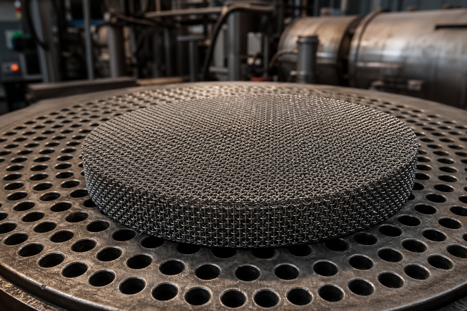
A screen pack is a single-layer or multi-layer assembly of woven wire mesh discs positioned between the extruder screw and the die, supported by a breaker plate, to filter contaminants from the polymer melt and generate controlled back pressure that improves melt homogeneity.
In simpler terms, it acts as a gatekeeper. Molten polymer is pushed by the screw through these layered mesh discs, where unwanted particles — metal fragments, paper, wood fibers, degraded polymer, and gels — are trapped before the melt continues toward the die. Different layer configurations and micron ratings can be selected depending on the level of decontamination required, pressure considerations, and the characteristics of the resin being processed.
Why Every Extrusion Line Depends on Screen Packs
Filtration alone does not capture the full purpose of this assembly. Beyond removing foreign particles, the resistance created by the mesh layers generates back pressure upstream of the breaker plate. This back pressure is actually beneficial — it enhances the melting and mixing processes along the screw, producing a more thermally uniform and homogeneous melt stream. As polymer process experts have noted, the screen pack and breaker plate combination serves this dual role of filtration and pressure regulation simultaneously.
Without proper filtration, you're essentially gambling with product quality. Contamination that slips through can cause visual defects, weak spots, and costly rejects — problems that compound quickly across a production run. And without adequate back pressure, melt consistency suffers, leading to dimensional variations and surface imperfections in the final extrudate.
This article walks through everything operators and engineers need to make smarter decisions about their filtration setup: the mechanics of melt flow through the assembly, material options and when each one applies, mesh count selection based on real contamination scenarios, the full filtration assembly beyond the mesh itself, application-specific requirements, lifecycle management, and sourcing strategies that reduce downtime. The right knowledge here does not just improve quality — it protects margins.
The real cost of a wrong selection, though, starts with understanding exactly how polymer melt interacts with each layer of mesh on its way to the die.
How Screen Packs Work Inside the Extrusion Process
Picture a river flowing through a series of increasingly fine nets. Debris gets caught, the current steadies, and what emerges on the other side is cleaner and more uniform. That is essentially what happens inside your extruder — except the river is molten polymer at several hundred degrees, the nets are precision-woven wire mesh, and the stakes involve product quality, machine protection, and profitability.
Most operators interact with screen packs during changeovers but rarely get a detailed look at what actually happens to the melt stream as it passes through. Breaking that process down step by step reveals why configuration choices matter so much — and why a seemingly small mismatch can cascade into real production problems.
How Polymer Melt Flows Through the Screen Pack
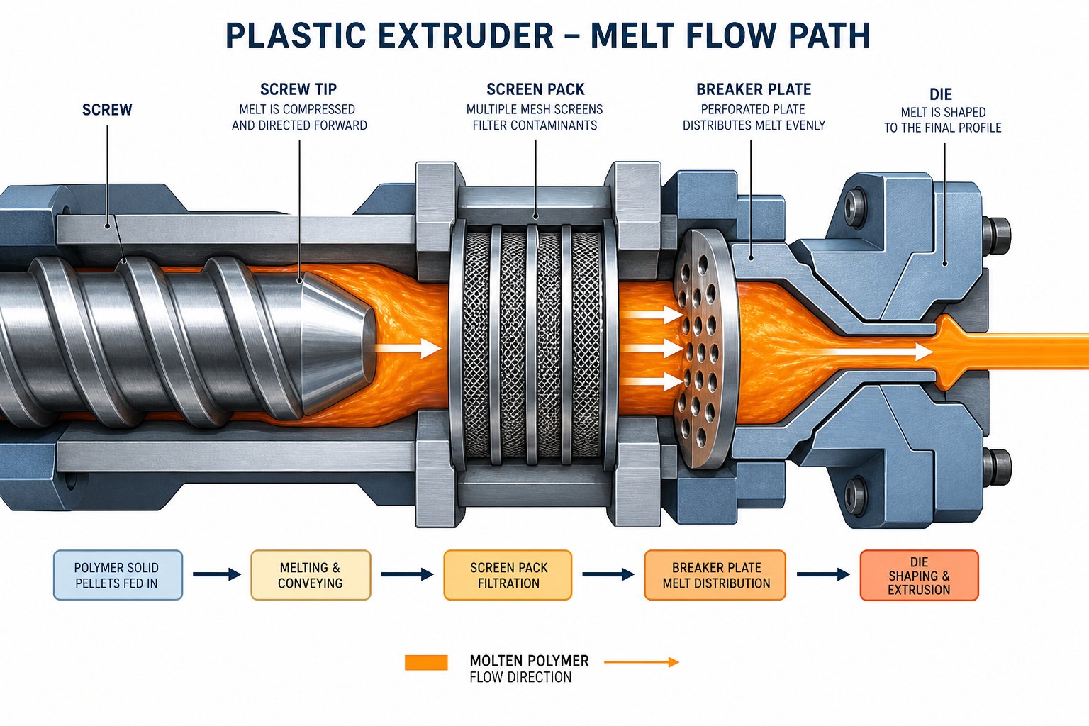
The journey from raw pellet to finished extrudate passes through several critical stages, but the filtration zone is where contamination control and melt conditioning happen simultaneously. Here is the sequence, from the moment the melt leaves the screw tip to the moment it enters the die:
- Screw metering section delivers the melt. The rotating screw pushes molten polymer forward under pressure. At the end of the screw, the melt exits as a semi-chaotic, rotationally influenced stream — not the clean, linear flow the die requires.
- Melt encounters the screen pack layers. The molten polymer is forced against the first layer of woven wire mesh. If a multi-layer configuration is used, the melt passes through each successive layer. Particles larger than the mesh openings are physically trapped on the upstream face of the filtration layer, while clean polymer flows through.
- Breaker plate provides structural support. Directly behind the mesh layers sits a perforated steel disc — the breaker plate. Its holes allow filtered polymer to pass through while mechanically supporting the mesh against the full force of the melt pressure. Without it, the thin wire mesh would deform, bulge, or rupture almost immediately under load.
- Rotational flow converts to linear flow. The breaker plate also serves a second, often overlooked function. The melt arriving from the screw carries a rotational memory — a spiraling motion imparted by the turning screw flights. The breaker plate's perforations break up this spiral pattern and redirect the flow into a more linear path, which is essential for uniform die filling.
- Filtered, conditioned melt enters the die. The polymer that emerges from the breaker plate is cleaner, more thermally uniform, and flowing in a straighter pattern. It then moves through the adapter and into the die, where it takes on its final cross-sectional shape.
This entire sequence happens continuously under pressure, and the condition of each component — the mesh integrity, the breaker plate holes, the seals around the assembly — directly influences what the die receives. A single torn mesh layer or a warped breaker plate can undo the benefits of even the best-chosen filtration configuration.
Understanding Back Pressure and Its Role in Melt Quality
When you force molten polymer through layers of fine wire mesh, resistance is inevitable. That resistance is back pressure — and contrary to what you might expect, it is not a problem to be minimized. It is a process variable to be managed.
A fresh screen pack creates a baseline level of flow resistance. As contaminants accumulate on the mesh surface over time, the effective open area shrinks and back pressure climbs progressively. This gradual increase is actually one of the most useful diagnostic signals available to operators — a rising pressure reading on the upstream gauge tells you the filtration is working and gives you a measurable indicator of when a changeover is needed.
But the real value of back pressure goes beyond diagnostics. The resistance created by the mesh layers pushes back against the screw's metering section, which produces several beneficial effects on melt quality:
- Improved mixing. The added resistance forces the polymer to spend more time under shear in the screw's compression and metering zones, resulting in better distributive mixing of additives, colorants, and fillers.
- More uniform melting. Back pressure helps eliminate unmelted or partially melted particles by ensuring the melt is more thoroughly processed before it reaches the filtration zone.
- Thermal homogeneity. A well-pressurized melt stream exhibits fewer temperature gradients. This consistency translates directly into more stable dimensions and surface quality in the finished product.
- Steadier output rate. Controlled resistance at the screen pack helps stabilize the volumetric flow rate, reducing the kind of surging or pulsation that shows up as periodic defects in the extrudate.
The key word here is controlled. Too little back pressure — from mesh that is too coarse or too few layers — and you lose these mixing and homogenization benefits. Too much — from an excessively fine mesh or a heavily contaminated pack that should have been changed — and you risk increased melt temperature from excess shear energy, higher motor load on the screw drive, reduced throughput, and potential mesh blowout. As extrusion process engineers consistently emphasize, excessive back pressure can lead to material degradation and increased energy costs that negate any filtration advantage.
Screen Pack Layer Configuration and Flow Dynamics
A single layer of mesh can filter polymer, but it is rarely the best approach. Most production environments use multi-layer configurations that combine different mesh counts in a specific sequence. The classic arrangement follows a coarse-fine-coarse pattern, and each layer serves a distinct purpose:
- First coarse layer (upstream side). This initial mesh faces the incoming melt and catches the largest contaminants — metal fragments, large degraded particles, paper fibers. It acts as a pre-filter that protects the finer mesh behind it from premature clogging and physical damage.
- Fine filtration layer (middle). This is where the precision work happens. The fine mesh — often ranging from 80 to 200+ mesh depending on the application — captures smaller particles like gels, crosslinked material, and fine degradation byproducts. This layer determines the overall filtration rating of the pack and contributes the most to back pressure.
- Second coarse layer (downstream side). Positioned between the fine mesh and the breaker plate, this layer provides mechanical support for the finer mesh above it. Under the high pressures typical in extrusion, a fine mesh pressed directly against a breaker plate can deform into the plate's holes — a condition called mesh dimpling — which weakens the mesh and can lead to premature failure.
Some operations go further, using four- or five-layer configurations with progressively graduated mesh counts. The idea is to create a filtration gradient — each layer captures a specific size range of contaminants, distributing the work across a larger total surface area. This graduated approach extends the usable life of the pack because no single layer bears the entire contamination burden.
The trade-off is always between filtration precision and pressure drop. A tighter fine-mesh layer catches smaller particles but restricts flow more aggressively, raising back pressure faster and requiring more frequent changeovers. A more open configuration lets higher throughput pass with lower pressure drop but allows finer contaminants to reach the die. The right balance depends entirely on what you are processing, the contamination level in your feedstock, and the quality demands of your finished product.
Multi-layer spot-welded packs offer an additional advantage: the layers are resistance-welded together as a single unit, which simplifies handling during changeovers and ensures the mesh layers maintain their intended alignment under pressure. For operations running recycled feedstocks with high contamination loads, these pre-assembled configurations reduce both changeover time and the risk of misaligned layers.
Choosing the right layer arrangement, though, is only half the equation. The material those mesh layers are made from has just as much influence on performance — especially when processing temperatures climb or chemically aggressive resins enter the picture.
Screen Pack Materials and When to Use Each One
You have picked your mesh count, decided on a layer configuration, and feel confident about the filtration side of the equation. But here is a question that catches many operators off guard: what is the wire mesh itself made from, and does the material actually matter for your specific resin and process temperature?
The short answer — it matters more than most people realize. A mesh that performs flawlessly with polyethylene at 220 °C might corrode, soften, or react when exposed to a fluoropolymer processed above 350 °C. Choosing the best screen pack material for high temperature polymers, or matching a softer alloy to a lower-temperature application, is not just a procurement detail. It directly affects filtration lifespan, melt contamination risk, and unplanned downtime.
Stainless Steel Screen Packs for High-Performance Applications
Stainless steel dominates the extrusion filtration market, and for good reason. Its composition — an iron-based alloy with chromium added at the molecular level — delivers significant resistance to corrosion, especially in the alkaline and acidic environments common in polymer processing. The chromium content also helps it resist oxidation at elevated temperatures, which is critical when you're running engineering thermoplastics or high-melt-index resins that push barrel temperatures well above 300 °C.
Most extruder filtration meshes use 300 series stainless steel (typically 304 or 316 grades). These grades handle the full range of polyolefins — polyethylene, polypropylene — as well as styrenics, ABS, nylon, polycarbonate, and PET without any compatibility concerns. For processors working with chemically aggressive resins like PVDF or certain fluoropolymers, 316 stainless offers improved resistance to chloride attack compared to 304.
Durability is the other major advantage. Stainless steel maintains its mesh profile under the high mechanical loads and temperature swings typical of extrusion. It resists abrasion from filled compounds containing glass fiber, mineral fillers, or carbon fiber — materials that would rapidly wear through softer alloys. If you're processing abrasive or high-temperature resins and you are unsure which material to choose, stainless steel is almost always the safe default. Some operations also use specialty alloys like Monel or Hastelloy for extreme chemical environments, though these come at a significant cost premium.
Brass, Copper, and Copper-Clad Steel Alternatives
Stainless steel handles most scenarios, but it is not the only option — and in certain applications, it is not even the best one.
Brass is a copper-zinc alloy — typically around 85% copper and 15% zinc in wire mesh applications. It is considerably softer and more malleable than stainless steel, which makes it easier to form, cut, and seat against breaker plates. For low-temperature polymers like certain grades of LDPE or EVA processed below 250 °C, brass mesh provides adequate performance and resists the oxidation-related corrosion that can affect plain carbon steel. One notable property of brass is its antimicrobial characteristic — copper ions on its surface can kill certain bacteria on contact — which occasionally makes it relevant for food-contact or medical-adjacent extrusion applications. The trade-off? Brass wears faster under mechanical stress and will deteriorate much more quickly if exposed to abrasive fillers or the higher temperatures demanded by engineering plastics. It is also worth noting that brass wire mesh has historically become more expensive than stainless steel, so the cost argument no longer favors it the way it once did.
Copper mesh is valued primarily for its excellent thermal conductivity. In extrusion, copper gauze is sometimes used as part of the filtration assembly — not as a primary contaminant barrier, but as a component that helps distribute heat more evenly across the melt stream as it passes through the pack. Copper is soft and prone to deformation under high pressure, so it is rarely used alone for filtration. Its best use is as a supplementary layer in configurations where thermal uniformity matters more than aggressive filtration.
Copper-clad steel offers a middle ground. The steel core provides the structural strength needed to withstand extrusion pressures without deforming, while the copper cladding adds thermal conductivity benefits. Copper clad steel screen pack applications tend to appear in operations that want improved heat transfer characteristics without sacrificing the mechanical integrity that pure copper cannot deliver. These are less common than stainless steel or brass options but fill a niche where both strength and thermal performance are priorities.
Matching Screen Pack Material to Your Polymer
The decision ultimately comes down to three variables: your processing temperature, the chemical nature of your resin, and the mechanical demands of your feedstock. Here is how the primary materials compare across these factors:
| Material | General Temperature Suitability | Common Polymer Compatibility | Typical Application |
|---|---|---|---|
| Stainless Steel (304/316) | Up to ~550 °C (continuous service varies by grade) | Polyolefins, nylon, PC, PET, ABS, fluoropolymers (316 preferred for aggressive chemistries) | General-purpose extrusion, engineering plastics, filled compounds, recycling lines |
| Brass (85 Cu / 15 Zn) | Up to ~250 °C | LDPE, EVA, soft PVC, low-temperature polyolefins | Low-temperature extrusion, food-contact applications, complex-shaped fabricated packs |
| Copper | Up to ~200 °C (softens under sustained load at higher temperatures) | Polyolefins and other low-temperature resins | Supplementary heat-distribution layer, not primary filtration |
| Copper-Clad Steel | Broader range than pure copper due to steel core | Polyolefins, styrenics, mid-range engineering resins | Applications needing both thermal conductivity and mechanical strength |
A practical rule of thumb: if you're running polyolefins at standard temperatures and your feedstock is relatively clean, stainless steel or brass will both work, but stainless steel offers longer service life and better abrasion resistance — making the stainless steel vs brass screen pack for extrusion comparison straightforward in most production environments. If your process involves filled compounds, regrind with potential metal contamination, or engineering resins above 300 °C, stainless steel is essentially the only durable option. Reserve copper and copper-clad steel for the specific situations where thermal conductivity outweighs other factors.
Selecting the right material protects the mesh from premature failure, but it does not address the other half of the performance equation — choosing the right mesh count. The tightest, most chemically resistant wire mesh in the world will still underperform if its openings are too coarse to catch the contaminants in your feedstock, or too fine to maintain reasonable throughput.
Choosing the Right Mesh Count for Your Application
So you have the right material — but how fine should the weave actually be? This is where many processors either over-filter and choke their throughput, or under-filter and send contaminants straight into the die. Knowing how to choose mesh count for your extruder screen pack starts with understanding what mesh count actually tells you and then matching it to the specific contamination profile of your feedstock.
Mesh Count Basics and What the Numbers Mean
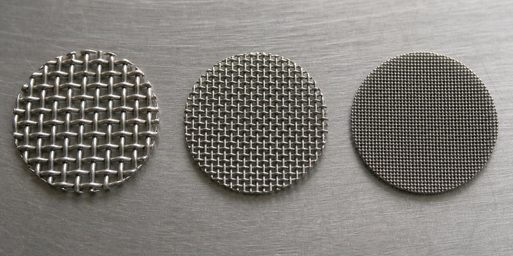
Mesh count refers to the number of openings per linear inch in a woven wire cloth. A 60 mesh screen has 60 openings per inch, while a 150 mesh screen has 150 — meaning the openings in the 150 mesh are significantly smaller. The relationship is intuitive once you see it: higher mesh count equals finer filtration equals smaller particles captured.
But finer filtration is not free. Every step up in mesh count reduces the open area available for polymer flow, which increases the pressure drop across the assembly. A 200 mesh layer restricts flow far more aggressively than an 80 mesh layer, so the melt has to work harder — and the pressure upstream of the breaker plate climbs faster. According to industry data from HAVER & BOECKER, most extrusion applications use square weave mesh in the 20 to 150 mesh range, with the specific choice driven by the balance between decontamination needs and acceptable operating pressure.
Think of it this way: selecting mesh count is a trade-off negotiation between how clean you need the melt and how much throughput and pressure headroom you can afford to sacrifice.
Matching Mesh Selection to Contaminant Type and Size
Your feedstock tells you what your filtration needs to catch. Virgin resin, straight from the pellet supplier, carries minimal contamination — perhaps occasional dust, a rare degraded particle, or minor gels. Lighter filtration in the 20 to 80 mesh range typically handles these materials without excessive pressure buildup, and screens can run for days before needing replacement.
Regrind and post-consumer recycled material are a completely different story. The screen pack mesh size for recycled plastic extrusion needs to account for a much wider contamination spectrum:
- Paper and wood fibers — common in post-consumer streams from label residue and mixed-waste collection.
- Metal fragments — staples, foil scraps, wire bits that survive upstream separation processes.
- Gels and crosslinked particles — semi-solid polymer clumps that did not fully melt and can cause fish-eye defects in films or weak spots in profiles.
- Degraded polymer — carbonized black specks from thermal degradation during previous processing cycles.
- Adhesive residues and dirt — sticky contaminants that accumulate rapidly on mesh surfaces and accelerate clogging.
Larger contaminants like metal fragments and paper fibers can be caught with relatively coarse mesh — 20 to 60 count. Gels and fine degradation particles, however, demand finer filtration in the 100 to 200 mesh range to keep them out of the finished product. Industry practice for blown film, where even particles above 80 to 100 microns create visible defects, routinely calls for 100 to 200 mesh filtration layers — and sometimes finer for high-clarity or barrier applications.
Layered Mesh Configurations for Optimal Filtration
You rarely rely on a single mesh to do all the work. The proven approach to screen pack mesh configuration for contaminant removal uses coarse to fine mesh layering in screen packs — stacking multiple layers so each one handles a different particle size range. A typical three-layer configuration places a coarse support mesh upstream, a fine filtration mesh in the middle, and another coarse protective mesh downstream against the breaker plate.
Why not just use the fine mesh alone? Two reasons. First, the coarse upstream layer acts as a pre-filter, trapping the largest debris before it can blind or physically damage the expensive fine layer. Second, the coarse downstream layer prevents the fine mesh from dimpling into the breaker plate holes under pressure — a failure mode that shortens mesh life dramatically.
The table below shows example layered configurations matched to common contamination scenarios. These are starting-point guidelines — your specific resin, throughput rate, and end-product quality standards should always inform the final selection.
| Contamination Level | Feedstock Example | Typical Layer Configuration (Flow Direction) | Fine Layer Mesh Count | Expected Pressure Behavior |
|---|---|---|---|---|
| Light | Virgin polyolefin, clean regrind | 20 mesh / 60-80 mesh / 20 mesh | 60-80 | Low baseline pressure; slow rise; long intervals between changes |
| Moderate | Industrial regrind, lightly contaminated post-industrial scrap | 20 mesh / 100-150 mesh / 40 mesh | 100-150 | Moderate baseline; steady rise; changes every shift or two |
| Heavy | Post-consumer recycled resin, mixed-waste streams | 20 mesh / 150-200 mesh / 40-60 mesh | 150-200 | Higher baseline; rapid rise; frequent changes, possibly multiple per shift |
Notice the pattern: as contamination severity increases, the fine filtration layer tightens while the support layers may also step up slightly to handle the greater volume of trapped debris. Some processors running heavily contaminated recyclate go even further, using four- or five-layer packs with graduated intermediate meshes — say 20 / 60 / 150 / 60 / 20 — to distribute the filtering load and extend the usable service window before a changeover is required.
Keep in mind that these configurations interact with every other variable in your process. A 150 mesh pack that runs comfortably on a large-diameter extruder at moderate throughput might generate unacceptable pressure on a smaller machine pushing the same resin at higher speeds. Testing and pressure monitoring are always the final arbiters — not a chart.
Of course, even the most carefully selected mesh configuration can only perform as well as the hardware holding it in place. The breaker plate, gaskets, and adapter housing all play roles that are easy to overlook — until one of them fails and your perfectly chosen filtration setup stops doing its job.
Breaker Plate and Screen Pack Assembly Explained
A perfectly selected mesh is only as effective as the hardware surrounding it. Operators sometimes focus exclusively on mesh count and material, then wonder why filtration performance degrades despite using the right configuration. The answer usually lies in one of the supporting components — a warped breaker plate, a degraded gasket, or a poorly seated adapter. Understanding how the breaker plate supports the screen pack in an extruder, and how every piece of the assembly contributes to filtration integrity, turns reactive troubleshooting into preventive awareness.
The Breaker Plate as Structural Foundation
Think of the breaker plate as the backbone of the entire filtration zone. It is a thick, perforated disc — typically hardened stainless steel — installed immediately downstream of the mesh layers. Its perforations, usually 4 to 8 mm in diameter and covering 30 to 40% of the plate surface, allow filtered polymer to pass through while distributing the full melt pressure load across the disc.
Without this structural support, the thin woven wire mesh would deform and rupture within minutes under the 100 to 400 bar pressures typical of thermoplastic extrusion. The breaker plate also performs a secondary but important role: disrupting the rotational flow pattern imparted by the screw. Each perforation acts as a mini-channel that redirects the spiraling melt into a more linear, axially aligned flow profile before it enters the die adapter. Older technical literature sometimes calls the breaker plate a "flow straightener" for exactly this reason.
One detail that often surprises operators is that the breaker plate itself can become a source of flow restriction. As filtration specialists at Parkinson Technologies have documented, certain polymers gradually deposit residue on the interior surfaces of the breaker plate holes — a phenomenon known as "plate out." Over time, this buildup reduces the cumulative open area, driving up pressure drop even when the mesh layers themselves are still clean. If your upstream pressure keeps climbing despite timely mesh changes, the breaker plate is the first place to inspect.
How Gaskets, Adapters, and Screen Packs Fit Together
The filtration zone is not just mesh and a breaker plate. Several components work in concert to form a sealed, pressure-tight assembly. Here is what each one does:
- Screen pack (woven wire mesh layers): Performs the actual filtration — trapping contaminants from the polymer melt based on mesh count and layer configuration.
- Breaker plate: Provides structural support for the mesh under melt pressure and converts rotational flow into linear flow before the die.
- Gasket or seal ring: A metal or high-temperature polymer ring seated around the perimeter of the assembly. It prevents molten polymer from leaking around the edges of the breaker plate and mesh, ensuring all melt is forced through the filtration layers rather than bypassing them.
- Adapter or screen changer housing: The machined steel housing that holds the breaker plate, mesh, and gasket in their correct position between the extruder barrel and the die. In manual setups, this is a bolted flange assembly; in automated systems, it is a hydraulic slide plate or piston housing that enables screen changes without full line stops.
- Retaining bolts and clamp ring: Secure the assembly under operating pressure. Uneven bolt torque can create gaps that allow polymer bypass or cause uneven pressure loading across the mesh.
Each component depends on the others. A gasket that has degraded from repeated thermal cycling will allow polymer to seep around the breaker plate, reducing filtration efficiency and creating a potential source of degraded material that contaminates the melt stream from the edges inward. An adapter housing with worn or scored sealing surfaces creates the same bypass problem — no gasket can compensate for a housing that no longer provides a flat, even mating surface.
Troubleshooting Assembly-Level Filtration Problems
When extrudate quality deteriorates or pressure readings behave unexpectedly, operators naturally suspect the mesh first. Sometimes that instinct is correct. But assembly-level issues can mimic — or amplify — mesh problems in ways that are easy to misdiagnose. Here are the most common culprits and their telltale signs:
- Warped or dished breaker plate: Repeated pressure cycling and thermal stress can cause the plate to bow slightly. Even a small deformation creates uneven support for the mesh, leading to localized stress points where blowout is more likely. If you notice mesh failures consistently in the same area of the disc, check the breaker plate for flatness with a straightedge.
- Plate-out buildup in breaker plate holes: A steady pressure increase despite fresh mesh — especially with resins prone to thermal degradation — signals that the breaker plate holes are narrowing from deposited residue. Removing and cleaning the plate resolves the issue, but traditional cleaning can require up to four hours of downtime depending on the severity and equipment design.
- Degraded or missing gasket: Polymer appearing at the edges of the assembly, or visible streaks of discolored material in the extrudate, often points to a gasket and seal ring for the extruder screen pack that has lost its sealing integrity. High-temperature cycling is the primary cause — standard gasket materials harden and crack over time, losing their ability to conform to the mating surfaces.
- Mesh dimpling into breaker plate holes: When the fine filtration layer is placed directly against the breaker plate without a coarse downstream support layer, the mesh can deform into the plate's perforations under pressure. This weakens the wire at each dimple point, creating a pattern of small tears that allow contaminants to pass through. The fix is straightforward: always include a coarse support mesh between the fine layer and the plate.
- Uneven bolt torque on the adapter flange: Inconsistent clamping force distorts the sealing surfaces and can create localized high-pressure zones on the mesh. Following a star-pattern torque sequence when assembling the flange prevents this issue.
The underlying principle across all these extruder filtration assembly troubleshooting tips is simple: the mesh is only one layer in a multi-component system. Inspecting the breaker plate for flatness and hole obstruction, checking gaskets for hardening or cracking, and verifying that the adapter housing provides a clean mating surface should all be part of every screen changeover routine — not just when problems appear.
With the hardware side covered, the next consideration is how these filtration assemblies perform differently depending on what you are actually making. A blown film line and a pipe extrusion line may use the same basic components, but their tolerance for contamination — and the consequences of getting filtration wrong — are worlds apart.
Screen Pack Requirements Across Extrusion Applications
A 150 mesh screen pack that delivers flawless results on a blown film line could be complete overkill on a thick-wall pipe extruder — and dangerously insufficient on a barrier film coextrusion setup. The same component, the same basic physics, but entirely different performance demands depending on what you are producing. Yet most filtration guides treat all extrusion as one category. It is not. Your application dictates everything from mesh fineness to changeover frequency, and getting this match wrong is one of the fastest ways to either waste money on unnecessary filtration or let defects slip into finished products.
Screen Pack Needs in Blown Film and Sheet Extrusion
Blown film is the most unforgiving extrusion process when it comes to melt cleanliness. Why? Because you are stretching molten polymer into a thin-walled bubble — often just 20 to 200 microns thick — where any solid particle above roughly 80 to 100 microns either punctures the wall, creates a fish-eye, or causes a visible streak. There is simply nowhere for contamination to hide in a film that thin.
The screen pack mesh for blown film extrusion typically falls in the 100 to 200 mesh range for standard LDPE and LLDPE films. High-clarity or optical-grade films push that even finer, into 150 to 200 mesh territory, while barrier structures using PA or EVOH in coextrusion lines may call for 200 to 250 mesh filtration — capturing particles down to 53 to 74 microns. Each extruder in a multilayer coextrusion stack needs independent filtration, because contamination in a single layer can disrupt adjacent layers and destabilize the bubble.
Sheet extrusion faces a similar but slightly more forgiving challenge. Sheets are thicker than films, so minor inclusions buried within the cross-section may not reach the surface. But surface-critical applications — clear PET thermoforming sheet, PMMA optical sheet, or high-gloss ABS — still demand tight filtration to prevent specks and gels that become visible defects after thermoforming or lamination. The screen pack requirements for sheet extrusion lines generally land in the 80 to 150 mesh range, balancing throughput against surface quality. Processors running high-volume sheet lines often find that 100 to 120 mesh provides the sweet spot — fine enough to catch problematic particles without creating the aggressive pressure drop that chokes output on large-diameter extruders.
Pipe, Profile, and Compounding Applications
Imagine extruding a 10 mm thick PE water pipe versus a 30-micron packaging film. The pipe wall is hundreds of times thicker, and minor inclusions that would be catastrophic in film simply get absorbed into the wall mass without affecting performance. This is exactly why screen pack selection for pipe and profile extrusion tends toward coarser filtration — typically 40 to 100 mesh — with the emphasis on catching hard contaminants like metal fragments that could create structural weak points rather than achieving optical-grade cleanliness.
Profile extrusion — window frames, weather stripping, trim — follows a similar pattern, though surface-visible profiles may need slightly finer mesh to prevent cosmetic defects on exposed faces. The key consideration for pipe and profile processors is not filtration fineness but filtration consistency: maintaining stable back pressure to ensure uniform wall thickness and dimensional accuracy throughout the run.
Compounding is the outlier. In a compounding extruder, the screen pack serves a fundamentally different purpose. Filtration matters, but the primary role shifts toward enhancing melt mixing and serving as a diagnostic tool. The best screen pack for a compounding extruder is often a moderate mesh — 40 to 80 range — chosen more for the back pressure it generates to improve additive dispersion and filler distribution than for aggressive particle removal. Process engineers on compounding lines regularly inspect used mesh to monitor resin quality trends, degradation patterns, and additive dispersion effectiveness — turning the spent screen into a window into process health.
Here is a quick-reference summary of how filtration priorities shift across these applications:
- Blown film: Finest filtration (100-250 mesh). Gels, specks, and particles above 80-100 microns create visible or structural defects. Frequent screen changes expected, especially with recycled content. Coextrusion lines need independent filtration per extruder.
- Sheet extrusion: Moderate-to-fine filtration (80-150 mesh). Surface quality is the primary driver, balanced against throughput demands on high-output lines. Clear and optical-grade sheets require the tighter end of this range.
- Pipe extrusion: Moderate filtration (40-100 mesh). Wall thickness absorbs minor inclusions. Focus is on catching hard particles that could compromise structural integrity, and on maintaining stable back pressure for dimensional consistency.
- Profile extrusion: Moderate filtration (60-120 mesh). Similar to pipe but with added attention to surface-visible faces. Mesh count may vary between cosmetic and hidden profiles produced on the same line.
- Compounding: Moderate filtration (40-80 mesh). Primary role is back pressure for mixing enhancement and process diagnostics rather than aggressive decontamination. Used screens provide valuable insight into resin and additive behavior.
The pattern is clear: the thinner and more visually exposed the final product, the finer the filtration needs to be. Thick-wall and internally used products tolerate coarser setups, while compounding operations treat the mesh as much as a process tool as a filter.
These application-specific demands intensify dramatically when recycled content enters the picture. Post-consumer feedstocks bring contamination challenges that no virgin-resin-based guideline fully prepares you for — and the filtration strategy required to handle them deserves its own dedicated discussion.
Screen Packs in Plastics Recycling Operations
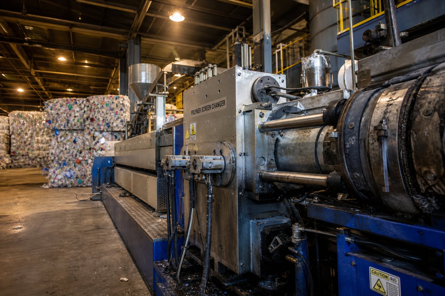
Processing virgin resin with minimal contamination is one thing. Running post-consumer bales through your extruder — material that spent its previous life as a yogurt cup, shampoo bottle, or detergent container — is an entirely different filtration challenge. The screen pack for a plastic recycling extruder does the same fundamental job as one on a virgin resin line, but it does it under far harsher conditions, at higher frequency, and with far less predictability in what it will encounter from batch to batch.
Recycling operations represent the fastest-growing segment of extrusion, driven by corporate sustainability commitments and legislative mandates for recycled content. Major brands like PepsiCo and Danone have pledged significant recycled content targets in their packaging — commitments that push the entire plastics supply chain toward processing more post-consumer resin (PCR). For filtration systems, this shift translates directly into harder work, shorter service life, and the need for smarter strategies.
Why Recycling Lines Demand More From Screen Packs
Virgin polyolefin pellets arrive at the extruder in a relatively controlled state — uniform composition, minimal foreign matter, predictable melt behavior. Post-consumer and post-industrial feedstocks arrive as a different animal entirely. Even after washing, sorting, and pelletizing at the recycling facility, the material carries residual contamination that virgin resin simply does not contain.
The practical result? Recycling lines load their filtration mesh dramatically faster than virgin resin lines. Where a clean PE film line might run an entire shift on one set of mesh discs, a recycling extruder processing post-consumer HDPE flake might need changes every 30 to 90 minutes — sometimes more frequently depending on the incoming material quality. This accelerated consumption rate is not a sign of a poorly chosen mesh. It is the inherent reality of processing material that was never designed for a second life through an extruder.
For maintenance teams and plant managers, the question of how often to change screen packs in recycling lines becomes a cost-planning exercise rather than a simple maintenance task. You are not just budgeting for occasional replacements — you are managing a consumable that may account for thousands of changes per year on a single line.
Contamination Challenges Unique to Post-Consumer Feedstock
The filtration challenges in post-consumer recycled plastic go well beyond what typical virgin-resin guidelines address. Consider what a bale of post-consumer plastic bottles actually contains after collection, sorting, and grinding:
- Label residue and adhesives: Paper-based and film-based labels leave fibrous and sticky residues that clog mesh rapidly. Pressure-sensitive adhesives are particularly problematic — they partially melt and smear across the mesh surface rather than collecting as discrete particles.
- Mixed polymer fragments: Even the best sorting systems miss occasional contaminants. A PP cap fragment in a PET bottle stream, or a PS cup lid mixed into HDPE, introduces incompatible polymer particles that do not melt uniformly and behave like solid contaminants in the melt.
- Dirt, sand, and mineral particles: Collection and storage expose post-consumer material to environmental contamination that commercial pellet handling avoids entirely.
- Metal fragments: Staples, foil liners, aluminum caps, and wire bits from collection equipment survive upstream magnetic separation more often than operators expect.
- Degraded and crosslinked polymer: Material that has already been heat-processed once — and potentially UV-exposed during its consumer life — contains degraded fractions that form gels and black specks in the recycled melt.
This cocktail of contaminants means the mesh is fighting on multiple fronts simultaneously. Some particles clog by physical blockage, others by adhesive smearing, and still others by gradual accumulation of semi-molten residues that slowly reduce effective open area. No single mesh count addresses all of these — which is why recycling operations tend toward multi-layer configurations with aggressive fine-mesh layers (150 to 200+ mesh) and accept the faster pressure rise that comes with them.
Screen Changers and High-Volume Recycling Filtration
When you are changing filtration every hour — or even more frequently — the economics of manual screen changes shift dramatically. Each manual change on a slide-plate system requires slowing or stopping the line, removing the loaded mesh, inserting fresh discs, and re-stabilizing the process. Multiply that disruption by 8 to 16 changes per shift, and the cumulative downtime, scrap generation, and operator labor become significant cost drivers.
This is precisely the scenario where the continuous screen changer vs manual screen change recycling decision tips decisively toward automation. Continuous screen changers — whether dual-bolt, dual-piston, or continuous-belt designs — allow mesh replacement while the line keeps running. One filter station stays active in the melt stream while the other is taken offline for changeover, minimizing the pressure disturbance that manual systems cannot avoid.
For high-throughput recycling lines processing 500 to 2,000+ kg/hour of contaminated feedstock, continuous filtration is not a luxury — it is an operational requirement. The contamination load simply does not allow the extended intervals between changes that would make manual operation practical. Smaller recycling operations running lower throughput or cleaner post-industrial scrap may still manage with manual or semi-automatic systems, but they need to budget for the associated downtime and scrap segments at each changeover event.
The broader industry trend is clear: as recycled content mandates grow and end-use quality standards for recycled resin tighten, filtration demands will only intensify. Recyclers are already moving toward finer mesh specifications — 200 mesh and beyond — to meet the optical and mechanical requirements of food-grade rPET, recycled-content packaging films, and other applications where PCR must perform at near-virgin quality levels. This trend means higher pressure drops, faster screen loading, and even greater reliance on continuous filtration technology to maintain both quality and throughput.
Managing these demands effectively requires more than just choosing the right mesh and equipment type. It requires a structured approach to the full screen pack lifecycle — from pre-installation inspection through the moment the mesh is spent and ready for replacement.
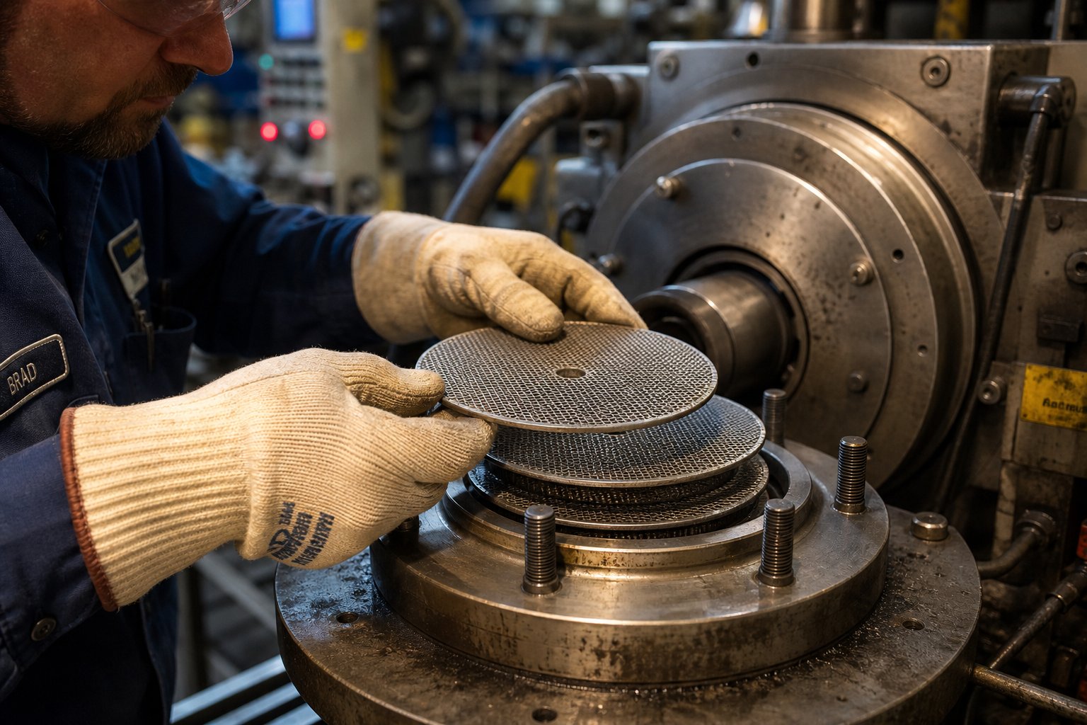
Screen Pack Lifecycle: How to Install, Monitor, and Replace the Right Way
Selecting the right mesh, material, and layer configuration is only half the battle. What happens during installation, day-to-day monitoring, and the eventual changeover determines whether that filtration assembly delivers its full service potential — or fails prematurely, costing you scrap, downtime, and frustration. A structured lifecycle approach turns each of these stages from a guessing game into a repeatable, reliable process.
Pre-Installation Inspection and Setup
Every screen pack change is a maintenance opportunity — not just for the mesh itself, but for the entire filtration zone. Rushing through installation without inspecting the supporting hardware is one of the most common reasons operators see repeat failures or unexplained pressure problems on freshly loaded assemblies.
Before any new mesh goes in, take these critical steps:
- Inspect the breaker plate for flatness and hole obstruction. Run a straightedge across the downstream face. Even slight dishing from thermal cycling creates uneven mesh support, concentrating stress in specific zones and inviting localized blowout. Check every perforation — polymer residue or "plate out" buildup inside the holes gradually narrows the open area, driving up pressure drop even on fresh mesh.
- Verify mesh count matches the process requirement. This sounds obvious, but in busy plants with multiple extruders running different resins, grabbing the wrong mesh from inventory happens more often than anyone admits. Confirm the mesh count, layer sequence, and disc diameter against the process specification before stacking.
- Check gaskets and sealing surfaces. Inspect the seal ring for hardening, cracking, or deformation. A degraded gasket allows polymer bypass around the filtration assembly — melt that skips the mesh entirely and carries unfiltered contamination straight to the die.
- Stack layers correctly. As the SPE Extrusion Division recommends, place a very coarse screen next to the breaker plate before positioning the finer mesh layers. This coarse layer prevents the fine mesh from lying flush against the breaker plate holes, which significantly increases the effective filtering area. Since most breaker plates have only 35% to 55% open area, this technique allows more of the fine mesh surface to actively participate in filtration rather than sitting blocked against solid steel.
One more detail that catches inexperienced operators: mesh discs must sit flat and wrinkle-free against each other. A folded edge or creased disc creates a gap in the filtration layer — an unfiltered channel that defeats the purpose of the entire assembly. If a disc does not lie flat when placed on the stack, discard it and use a fresh one.
Monitoring Pressure and Recognizing Failure Signs
You have installed the mesh correctly, brought the line up to speed, and everything looks good. What now? This is where disciplined monitoring separates operations that catch problems early from those that discover them in the scrap bin.
Screen pack pressure drop monitoring during extrusion is the single most valuable real-time indicator of filtration condition. It works like this: pressure sensors installed upstream and downstream of the filtration assembly give you two readings. The difference between them — the pressure differential — tells you how much resistance the mesh is creating. A freshly installed pack shows a low, stable differential. As contaminants accumulate, that differential climbs steadily.
Here is what to watch for during normal operation:
- Baseline pressure. Record the clean-screen pressure differential immediately after startup and stabilization. This becomes your reference point for everything that follows.
- Gradual pressure rise. A slow, steady increase in the pressure differential is normal — it means the mesh is doing its job and trapping contaminants. Track this rise over time. Keeping a log of pressure readings for each production run reveals trends that help you predict when the next changeover will be needed rather than reacting to a crisis.
- Rate of rise. How fast the differential climbs tells you about your feedstock. A faster-than-expected rise suggests higher contamination levels in the incoming material — useful diagnostic information, especially when switching resin lots or suppliers.
- Extrudate visual quality. Pressure readings are not the whole picture. Periodically inspect the extrudate surface for specks, gels, streaks, or color inconsistencies. These visual indicators sometimes appear before pressure data signals a problem — particularly when a small tear in the mesh allows localized contamination passage without significantly changing overall flow resistance.
Knowing when to replace a screen pack in your extrusion line depends on establishing a maximum acceptable pressure differential for your specific process. This threshold varies by machine size, resin type, and product tolerance — there is no universal number. Most operations set it based on experience: the point where melt temperature starts rising from excess shear energy, motor load approaches its upper limit, or output rate drops below the acceptable threshold.
The signs of screen pack failure in an extruder are distinct from normal end-of-life clogging and demand immediate action:
- Sudden pressure drop. A sharp, unexpected decrease in upstream pressure — especially without a corresponding change in screw speed — typically indicates mesh blowout. The mesh has ruptured, and unfiltered polymer is now flowing freely to the die. Stop the line and inspect immediately.
- Visible contamination in extrudate. Black specks, gels, or foreign particles suddenly appearing in previously clean output signal that the filtration barrier has been compromised. Even a pinhole tear in the fine mesh layer can allow a stream of contaminants through.
- Pressure spikes followed by drops. Erratic pressure behavior — rapid surges followed by sudden releases — often indicates a mesh that is partially torn and flexing under load. Each flex opens the tear wider, making complete failure imminent.
Step-by-Step Screen Pack Replacement Procedure
When the pressure differential reaches your predetermined threshold — or when failure signs demand immediate action — a systematic changeover procedure minimizes downtime, protects equipment, and ensures the fresh assembly performs from the first meter of extrudate. Here is the step-by-step screen pack change procedure most experienced operators follow:
- Reduce screw speed and lower throughput. Gradually reduce the screw RPM to slow melt delivery and decrease the pressure on the filtration assembly. Do not shut the screw off abruptly — a sudden stop can cause pressure surges and material stagnation.
- Relieve residual pressure. On manual slide-plate or bolt-type screen changers, follow the manufacturer's procedure for depressurizing the filtration housing. This typically involves loosening clamp bolts in a controlled sequence.
- Remove the loaded assembly. Slide out the breaker plate and spent mesh. On bolt-type changers, unbolt the adapter flange and extract the assembly. Use appropriate PPE — these components are at full melt temperature and will cause severe burns on contact.
- Inspect the breaker plate and housing. Before inserting fresh mesh, examine the breaker plate for warping, hole obstruction, and surface scoring. Check the adapter housing sealing surfaces for wear or polymer buildup. Clean as needed — this is the only opportunity to address these components without an additional line stop.
- Stack and seat the fresh screen pack. Arrange mesh layers in the correct sequence — coarse support layer against the breaker plate, fine filtration layer in the middle, coarse pre-filter layer facing upstream. Verify each disc is flat, unwrinkled, and correctly sized for the breaker plate diameter.
- Install a fresh gasket if needed. If the seal ring shows any signs of hardening, cracking, or permanent compression set, replace it. A compromised gasket undermines the entire filtration assembly regardless of mesh quality.
- Reassemble and secure the housing. Slide or bolt the assembly back into position. For flanged connections, tighten bolts in a star pattern to ensure even clamping force across the sealing surface.
- Gradually increase screw speed. Bring the screw back up to operating RPM slowly, monitoring both upstream and downstream pressure as the melt re-establishes flow through the fresh mesh. A gradual ramp-up prevents pressure shock that can damage a new assembly.
- Record the clean-screen baseline pressure. Once the process stabilizes, document the new pressure differential. This reading becomes the reference point for monitoring the lifecycle of the freshly installed pack.
- Inspect the spent mesh. Before discarding the removed assembly, examine the used mesh. The color, distribution, and type of trapped material provide diagnostic insight into feedstock contamination levels, degradation trends, and whether the current mesh configuration is appropriate for the material being processed.
That final step — inspecting the spent mesh — is one of the most underutilized diagnostic tools in extrusion. A screen that loads evenly across its surface tells you the melt distribution is healthy. One that clogs heavily in one area may indicate flow channeling from a worn screw or uneven temperature zones. Dark, carbonized deposits concentrated at the edges can point to stagnation in the adapter housing. Each spent screen tells a story about your process, if you take a moment to read it.
Consistency across all of these steps depends on more than operator skill. It requires reliable access to correctly specified mesh, breaker plates, gaskets, and adapter components — ideally sourced as a coordinated system rather than pieced together from whatever happens to be on the shelf.
Sourcing Screen Packs and Extruder Filtration Components
You have selected the right mesh count, confirmed the material matches your resin, stacked the layers correctly, and established a disciplined changeover routine. But all of that falls apart if you cannot get the parts you need when you need them. A blown mesh at 2 AM on a Saturday does not care about your purchasing department's lead time negotiations. Where to buy screen packs for plastic extruders — and how to structure that supply relationship — is the final piece of the puzzle that separates plants running smoothly from plants scrambling through unplanned downtime.
Why System-Level Sourcing Reduces Downtime
Here is a scenario that plays out in extrusion plants more often than it should: the maintenance team orders mesh discs from one vendor, breaker plates from another, and gaskets from a third. Each component meets its own specification on paper. But when assembled together, the mesh diameter runs slightly undersized for the breaker plate recess, the gasket thickness does not quite match the adapter groove depth, and the whole assembly leaks polymer from the edges on the first startup.
This is the compatibility trap — and it stems from treating filtration components as isolated commodity purchases rather than parts of a single integrated system. A supplier who understands the complete assembly knows how the mesh outer diameter relates to the breaker plate pocket, how the gasket thickness interacts with the adapter housing seal surface, and how dimensional tolerances across all three components stack up under operating pressure and temperature.
Sourcing the full filtration assembly — mesh, breaker plate, gasket, and adapter components — from a single supplier who manufactures or verifies dimensional compatibility across the set eliminates the mismatch risk entirely. You get parts that fit together the first time, every time, without the trial-and-error waste that fragmented sourcing creates.
Custom Fabrication for Legacy and Non-Standard Extruders
Imagine running a reliable 20-year-old extruder that still produces excellent output — but the original manufacturer has closed its doors or discontinued spare parts for your model. You need a replacement breaker plate, a set of mesh discs in a non-standard diameter, or an adapter ring with a profile that no catalog supplier stocks. What do you do?
This is where custom extruder screen pack fabrication from drawings becomes essential. Manufacturers who can produce filtration components from your engineering drawings, physical samples, photographs, or even measured dimensions of the existing part give legacy equipment a viable path forward. Instead of reverse-engineering a workaround or settling for a close-enough catalog part that requires modification, you get a component built to your machine's exact specifications.
Suppliers like NANHAIYA specialize in this approach — manufacturing extruder spare parts including screen packs, breaker plates, filter adapters, and related components to specification from drawings, samples, photos, or measured dimensions. For maintenance teams managing mixed fleets of extruders from different manufacturers and eras, this kind of fabrication capability means you are not locked into OEM pricing or forced to retire functional equipment simply because a filtration component is no longer available through the original channel.
The value extends beyond legacy machines. Even current-production extruders sometimes require non-standard mesh configurations, custom breaker plate hole patterns optimized for a specific resin, or adapter modifications that catalog parts cannot accommodate. A fabrication partner who works from your specifications — rather than asking you to adapt to their catalog — gives you full control over your filtration setup.
Building a Reliable Screen Pack Supply Strategy
Reactive purchasing — ordering replacement mesh only after a blowout or a failed changeover — is one of the most expensive habits in extrusion maintenance. Every hour your line sits idle waiting for parts carries a cost in lost production, scrapped material, and delayed shipments that dwarfs the price of the components themselves.
A smarter extruder filtration components sourcing strategy starts with inventory planning. Maintenance teams should stock the mesh configurations they use most frequently — the standard layer combinations for each extruder and resin family on the floor. Track consumption rates by machine and by material type. Recycling lines, as discussed earlier, consume filtration at dramatically higher rates than virgin resin operations, so inventory buffers for those lines need to reflect that reality. Logging pressure data and changeover frequency per production run gives you the historical basis to forecast demand accurately rather than guessing.
Beyond inventory levels, the supplier relationship itself matters. When evaluating a screen pack and breaker plate supplier, these are the factors that separate a reliable partner from a parts catalog:
- Custom fabrication capability: Can the supplier manufacture components from your drawings, samples, or measured dimensions — especially for non-standard or discontinued equipment? NANHAIYA's extruder spare parts program is built around this exact capability, serving maintenance teams and plant buyers who need parts produced to their specifications rather than adapted from generic stock.
- Material traceability: Can the supplier document the alloy grade and source of the wire mesh and breaker plate material? Traceability matters most for food-contact, medical, or regulated applications where material certification is a compliance requirement — not just a quality preference.
- Dimensional accuracy: Mesh disc diameter, breaker plate pocket dimensions, and gasket groove tolerances all need to be held tightly. Ask about inspection methods and tolerance capabilities before committing to a new supplier, not after receiving the first order.
- Mesh count verification: Reputable suppliers verify the actual mesh count of woven wire cloth rather than relying solely on mill certifications. A mesh labeled as 150 count that actually measures at 140 changes your filtration performance and pressure behavior in ways that are difficult to diagnose from the operator's side of the extruder.
- Turnaround time: Standard items should ship quickly from stock. Custom-fabricated parts should have clear, reliable lead times that allow you to plan changeovers and maintenance windows without emergency expediting fees.
- Assembly-level understanding: The supplier should understand how their components interact with the rest of the filtration assembly — not just sell you a disc or a plate in isolation. This knowledge shows up in their ability to flag potential compatibility issues, suggest configuration improvements, and support troubleshooting when problems arise.
Establishing this kind of supply partnership is not a one-time purchasing decision. It is an ongoing relationship that pays dividends every time a changeover goes smoothly, every time a custom part arrives on spec and on time, and every time your line keeps running because the right components were already on the shelf. In extrusion, uptime is everything — and the sourcing strategy behind your filtration components is one of the most controllable variables in protecting it.
Frequently Asked Questions About Screen Packs in Extrusion
1. What is a screen pack in plastic extrusion and what does it do?
A screen pack is a layered assembly of woven wire mesh discs installed between the extruder screw and die, supported by a breaker plate. It serves two critical functions simultaneously: filtering contaminants such as metal fragments, gels, degraded polymer, and foreign particles from the molten plastic, and generating controlled back pressure that improves melt mixing, thermal uniformity, and output consistency. Without a properly functioning screen pack, contamination passes directly into the die, causing visual defects, structural weak spots, and costly product rejects.
2. How do I choose the right mesh count for my extruder screen pack?
Mesh count selection depends on your feedstock contamination level and end-product quality requirements. Virgin polyolefins with minimal contamination typically need 20 to 80 mesh. Post-industrial regrind with moderate contamination calls for 100 to 150 mesh. Heavily contaminated post-consumer recycled material often requires 150 to 200+ mesh. Most processors use a coarse-fine-coarse layered configuration, where the fine middle layer sets the filtration precision while coarse outer layers provide pre-filtering and structural support against the breaker plate. Always validate your selection by monitoring pressure differential and inspecting extrudate quality during production.
3. How often should screen packs be changed in a recycling extruder?
Changeover frequency in recycling lines varies widely based on feedstock quality and mesh fineness. A clean virgin PE line might run an entire shift on one screen pack, while a recycling extruder processing post-consumer HDPE flake may need changes every 30 to 90 minutes due to heavy contamination from labels, adhesives, mixed polymers, and degraded material. Operators should track upstream-to-downstream pressure differential as the primary indicator. When the differential reaches a predetermined threshold where melt temperature rises, motor load increases, or throughput drops, it is time to change. High-volume recycling operations often invest in continuous screen changers to minimize downtime from frequent replacements.
4. What is the difference between stainless steel and brass screen packs?
Stainless steel (typically 304 or 316 grade) handles temperatures up to approximately 550 degrees Celsius, resists corrosion from aggressive chemistries, and withstands abrasion from glass-fiber-filled or mineral-filled compounds. It is the default choice for engineering plastics, recycling lines, and most general-purpose extrusion. Brass, a copper-zinc alloy, is softer and limited to roughly 250 degrees Celsius, making it suitable only for low-temperature polymers like LDPE or EVA. While brass was historically cheaper, stainless steel now often matches or beats it on price while offering superior durability, longer service life, and broader chemical compatibility.
5. Where can I buy custom screen packs and breaker plates for non-standard extruders?
For legacy or non-standard extruders where OEM parts may be discontinued or unavailable, suppliers like NANHAIYA (nhyscrews.com) manufacture screen packs, breaker plates, filter adapters, and related extruder spare parts to specification from engineering drawings, physical samples, photographs, or measured dimensions. This custom fabrication approach eliminates the need to retrofit generic catalog parts. When evaluating any supplier, prioritize material traceability, dimensional accuracy, mesh count verification, turnaround time, and their understanding of how filtration components interact as a complete assembly rather than isolated parts.
Written by
Nanhaiya Technical Team
Zhoushan Nanhaiya Plastic Machinery Co., Ltd.
The Nanhaiya technical team supports screw and barrel manufacturing projects through application review, technical communication, custom manufacturing coordination, and production and quality control.
Discuss Your Application
Related Articles
More insights on screw barrel technology and plastics processing.

What Nobody Tells You About Screw Barrel For Plastic Machine Design
Oct 10, 2026
Learn how screw barrel for plastic machine design affects melt quality, throughput, and wear life. Covers geometry, resin matching, troubleshooting, and sourcing.
Read Article
Single Screw Extruder for Sheet: Stop Guessing, Start Specifying
Oct 9, 2026
Learn how to specify a single screw extruder for sheet production. Covers screw geometry, resin-specific processing, troubleshooting, and maintenance best practices.
Read Article
PE Pipe Extruder Machine: What Datasheets Won't Tell You
Oct 9, 2026
Learn how a PE pipe extruder machine works, key specs explained, material grade selection, maintenance tips, and buyer guidance beyond the datasheet.
Read ArticleLooking for something else?
Search by material, symptom or product and jump straight to the relevant page.
These are navigation suggestions based on keyword matching — not a quotation, not a delivery commitment, and not a substitute for engineering review. Final specification is confirmed by our engineers against your drawings and processed material.
Need help with screw barrel selection?
Share your machine model, processed material and application. Our team can help with pricing and technical support.