

What a PVC Water Pipe Extrusion Line Is and Why It Matters
Imagine a factory floor where powdered resin enters one end of a production system and fully formed, precision-measured water pipes emerge at the other — continuously, hour after hour, with no interruption. That is exactly what a PVC water pipe extrusion line does. But what makes up this system, and why has PVC become the undisputed standard for water piping worldwide?
What Is a PVC Water Pipe Extrusion Line
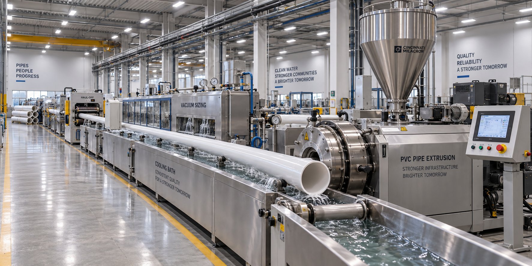
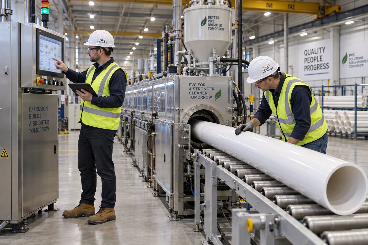
At its core, a PVC water pipe extrusion line is a series of synchronized machines working together as a single continuous manufacturing system. Raw PVC compound — typically a dry blend of resin, stabilizers, lubricants, and other additives — is fed into the line, melted, shaped into a hollow tube, cooled, sized, cut, and finished into pipes ready for installation. Each station in the pipe extrusion line handles a specific transformation, and the quality of the final product depends on how precisely these stations coordinate with one another.
A PVC water pipe extrusion line is a continuous manufacturing system that converts PVC compound into finished water supply pipes through a sequence of integrated processing stations — including feeding, melting, shaping, calibrating, cooling, hauling, cutting, and finishing — all operating in unison to produce dimensionally accurate pipe at high volume.
These lines produce pipes used across a broad spectrum of applications: potable water distribution, non-potable supply networks, agricultural irrigation, residential plumbing, and industrial fluid transport. The pipe extrusion process itself — melting thermoplastic material and forcing it through a die to create a continuous profile — is a well-established form of vinyl extrusion that has been refined over decades to meet increasingly demanding quality and safety standards.
Why PVC Dominates Water Pipe Manufacturing
PVC's dominance in the water pipe sector is not accidental. Several material properties converge to make it the most practical choice for manufacturers and end users alike:
- Corrosion resistance: Unlike metal alternatives, PVC does not rust, pit, or scale, which means longer service life and cleaner water delivery.
- Low cost: PVC resin is among the most affordable engineering thermoplastics, and PVC extrusion lines operate efficiently at high throughput, keeping per-meter production costs low.
- Light weight: PVC pipes weigh significantly less than ductile iron or concrete equivalents, reducing transportation costs and simplifying installation.
- Long service life: Properly manufactured extruded PVC pipes routinely deliver 50-plus years of reliable service in buried infrastructure.
- Health-contact compliance: For potable water applications, PVC pipes can be certified to NSF/ANSI 61 — an independent, accredited standard that evaluates health effects of drinking water system components through rigorous extraction testing and toxicological review. Rigid PVC pipe formulations do not contain phthalate plasticizers, addressing a common concern among specifiers. Pressure ratings, meanwhile, are governed by standards such as ASTM D1785, giving engineers clear design parameters.
This combination of performance, economy, and regulatory acceptance explains why PVC pipe extrusion lines represent the highest-volume segment of vinyl extrusion equipment installed globally. Whether a manufacturer targets municipal infrastructure or residential plumbing markets, a well-configured pipe extrusion line is the production backbone.
This guide is designed as a single, comprehensive resource — bridging foundational knowledge of how PVC extrusion works with the practical, buyer-level detail needed to evaluate equipment, troubleshoot defects, and build a reliable supply chain. Every station in the line plays a role in the final pipe's quality, and understanding those roles starts with knowing exactly what sits between the raw material hopper and the finished pipe stacker.
Every Component in a PVC Water Pipe Extrusion Line Explained
A PVC water pipe extrusion line is not a single machine — it is a carefully sequenced chain of stations, each performing a distinct transformation on the material. Remove or misconfigure any one station and the finished pipe suffers. Here is exactly what each component does, presented in the order the material encounters it from hopper to stacker.
- Raw material feeding system — delivers the PVC dry blend from storage into the pipe extruder at a controlled, consistent rate.
- Extruder (conical twin-screw or single-screw) — melts, compresses, and homogenizes the compound into a uniform melt.
- PVC extrusion die and adapter — shapes the melt into a hollow, cylindrical profile.
- Vacuum calibration tank — locks the pipe's outer diameter and roundness while the material is still soft.
- Spray cooling tanks — progressively solidify the pipe wall from outside to inside.
- Haul-off unit — pulls the pipe through downstream equipment at a precisely controlled speed.
- Cutter — cuts the continuous pipe to the required length.
- Belling/socketing machine — forms an expanded socket on one end for push-fit jointing (where applicable).
- Inkjet marking system — prints product identification, size, standard, and production data onto the pipe surface.
- Automatic pipe stacker or dump table — collects and organizes finished pipes for packaging and shipment.
Every station listed above directly influences dimensional accuracy, surface finish, or mechanical performance of the final product. Let's walk through the most critical ones in detail.
Extruder and Die Head
The pipe extruder is the heart of any PVC pipe extrusion machine. Its job is deceptively simple — take powdered compound in, push homogeneous melt out — yet the engineering behind that transformation is anything but basic. Two main extruder types serve PVC pipe production: single-screw and conical twin-screw. Single-screw machines work well when processing pre-compounded PVC pellets, offering a simpler design at lower cost. However, the industry standard for rigid PVC water pipe manufacturing is the conical twin-screw extruder. Its two intermeshing, tapered screws provide superior shear control, self-wiping geometry that reduces material stagnation, and the ability to process PVC dry blends directly — eliminating the need for a separate pelletizing step.
Immediately downstream of the extruder sits the PVC extrusion die, connected through an adapter. The die transforms the solid cylindrical melt stream into a hollow tube. Die design — specifically the gap width, land length, and flow channel geometry — determines initial wall thickness uniformity and surface quality. Think of the die as the mold that gives the pipe its first shape; any imbalance in melt distribution here carries through every downstream station.
Vacuum Calibration and Cooling Systems
When the soft, molten tube exits the die, it has roughly the right shape but zero structural integrity. The vacuum calibration tank is where the pipe becomes a pipe. Inside this sealed, water-cooled chamber, a slight vacuum draws the still-pliable tube outward against a precision sizing sleeve, fixing the outer diameter and ensuring roundness. The vacuum level and sleeve dimensions must match the target pipe specification exactly — too much vacuum distorts the pipe, too little allows it to sag or shrink unevenly.
After initial calibration, the pipe enters one or more spray cooling tanks. These tanks use water spray nozzles to remove heat progressively, solidifying the pipe wall from the outside inward. The cooling water temperature, flow rate, and tank length all matter. Rush the cooling and you build internal stresses that can warp the pipe later; cool too slowly and the production line speed drops. For large-diameter pipes, water bath methods alone can cause uneven cooling between the top and bottom of the pipe, which is why spray configurations are often preferred for consistent results in tubing extrusion of this scale.
Haul-Off, Cutter, and Downstream Equipment
The haul-off unit — typically a caterpillar-track or belt-type puller — grips the cooled pipe and draws it through the line at a constant speed synchronized with the extruder output. This is more critical than it sounds: unstable haul-off speed causes pipe diameter to fluctuate, and variations in haul-off force can create surface waviness. Modern caterpillar haul-offs use multiple rubber-padded tracks arranged around the pipe circumference, with pneumatically or hydraulically adjustable clamping force to prevent surface damage while maintaining grip.
At the end of the line, a planetary or chipless saw cutter receives a signal at the programmed pipe length, clamps onto the moving pipe, travels with it during the cut, and resets. Chipless cutters are favored for PVC because they produce clean edges without generating dust or swarf that could contaminate the production environment.
Beyond cutting, several post-extrusion stations add the finishing touches. A belling machine heats one pipe end and expands it into a socket for easy field assembly. An inkjet printer marks each pipe with diameter, pressure class, production date, and applicable standards. Finally, automatic stackers or dump tables organize the finished pipes — turning a continuous tubing extrusion process into neatly bundled, shipment-ready inventory.
Each of these components exists because a specific quality attribute depends on it. Dimensional accuracy traces back to the die, calibrator, and haul-off. Surface finish originates at the extruder and die temperature settings. Mechanical performance is shaped by the entire thermal history — from barrel zones through cooling tanks. The real challenge for any pipe extrusion machine operator is not running individual stations, but orchestrating the entire line so that every station reinforces the others.
UPVC vs. CPVC vs. PVC-O and How Each Changes the Line
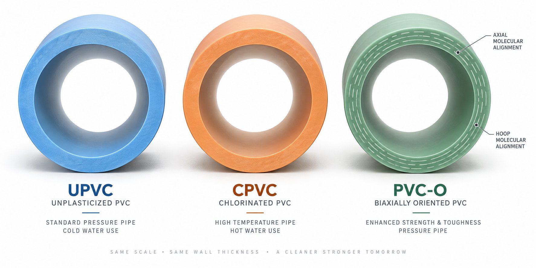
The components of a pvc water pipe extrusion line stay largely the same from one installation to the next — but the way those components are configured shifts dramatically depending on the type of PVC being processed. Three material variants dominate water pipe markets, and each one demands a distinct pvc extrusion process. Choosing the wrong settings or equipment layout for a given material does not just hurt efficiency — it can produce pipe that fails in service.
UPVC Water Pipe Extrusion Essentials
Unplasticized PVC — commonly called UPVC or U-PVC — is the workhorse of cold-water supply piping. It contains no plasticizers, which gives it excellent rigidity and pressure-bearing capability but also makes it more demanding to process. Standard pvc pipe extrusion lines built around conical twin-screw extruders handle UPVC effectively, with barrel temperatures typically set in the 160-190 °C range. The rigid formulation leaves very little room for thermal error. Push temperatures even slightly too high and the compound begins to degrade, releasing hydrochloric acid gas. Stay too low and the melt remains poorly plasticized, producing rough surfaces and weak weld lines in the finished pipe.
Downstream, UPVC lines use conventional vacuum calibration and spray cooling. Because the material solidifies into a stiff wall relatively quickly, cooling tank lengths can be shorter compared to flexible PVC products — but they still need to be long enough to prevent residual stress buildup in thicker-walled pipe.
CPVC Lines for Hot Water Applications
When the application involves hot water — think residential hot-water plumbing or industrial process piping — manufacturers turn to CPVC, a chlorinated variant with a significantly higher glass transition temperature. That elevated thermal resistance is exactly what makes CPVC suitable for hot-water service, but it also raises the processing bar considerably.
CPVC requires barrel and die temperatures roughly 10-20 °C above those used for standard UPVC, pushing into ranges where thermal degradation risk intensifies. Screw geometry often needs modification: shorter compression zones, adjusted flight depths, and tighter clearances help manage the higher melt viscosity without generating excessive shear heat. Melt pressure control becomes more precise, and operators typically reduce screw speed to extend residence time just enough for thorough plasticizing without overheating.
Downstream adjustments matter too. CPVC's higher softening point means the extruded pipe retains heat longer, so cooling tanks must be extended or spray intensity increased to achieve full solidification before the haul-off grips the pipe.
PVC-O Biaxially Oriented Pipe Production
PVC-O represents a fundamentally different approach. Rather than simply extruding and cooling, this pvc plastic extrusion method adds an inline orientation stage that transforms the molecular structure of the pipe wall. The result? A biaxially oriented pipe with impact resistance and pressure ratings that far exceed standard extruded pvc of the same wall thickness.
The process begins with producing a conventional UPVC pressure pipe — the "preform." This preform is then reheated to a carefully controlled temperature window of 85-100 °C and expanded radially using internal pressure. Diameter stretching ratios typically range between 1.6 and 2.1, with higher ratios yielding higher material strength classifications. Rapid cooling immediately follows the expansion, locking the newly aligned molecular chains into place. Bi-orientation — stretching in both the circumferential and axial directions simultaneously — produces the superior mechanical properties that define PVC-O pipe. A length stretch of approximately 20 percent during this stage also improves integrated socket strength.
This inline orientation stage is a major addition to the production line, requiring dedicated heating zones, expansion equipment, and precision temperature sensors that standard UPVC or CPVC lines simply do not include.
| Parameter | UPVC | CPVC | PVC-O |
|---|---|---|---|
| Typical Application | Cold-water supply, irrigation, drainage | Hot-water plumbing, industrial hot-fluid transport | High-pressure water mains, demanding infrastructure |
| Processing Temperature Range | 160-190 °C | 170-210 °C | Standard extrusion (160-190 °C) + orientation at 85-100 °C |
| Screw Design Considerations | Standard conical twin-screw; balanced shear and throughput | Modified compression zone; tighter clearances for higher-viscosity melt | Standard conical twin-screw for preform; orientation stage is mechanical, not screw-dependent |
| Downstream Equipment Differences | Conventional vacuum calibration and spray cooling | Extended cooling tanks; higher spray intensity | Added inline reheating, radial expansion unit, rapid cooling, and length-stretch system |
The takeaway here is straightforward: the same base polymer family requires meaningfully different line configurations depending on the end product's service conditions. A line optimized for UPVC cold-water pipe cannot simply switch to CPVC production without hardware and process adjustments — and PVC-O demands an entirely additional production stage. Understanding these distinctions is essential before specifying equipment, because the material choice dictates everything from barrel temperatures and screw geometry to cooling infrastructure and floor space requirements.
Raw Material Preparation and Feeding That Most Guides Overlook
Material selection and line configuration matter enormously — but even the most perfectly tuned extruder line cannot compensate for poorly prepared raw material. The stages that happen before PVC compound ever reaches the extruder feed throat are arguably the most underappreciated link in the entire production chain. Get them wrong and you'll chase quality problems through every downstream station without ever finding the real source.
Hot and Cold Mixing Units
PVC resin on its own is not ready for extrusion. It must first be blended with a precise recipe of stabilizers, lubricants, processing aids, fillers, and pigments to form a homogeneous dry blend. This blending happens in a two-stage mixing system that anchors any serious plastic pipe production line.
The hot mixer — a high-speed, vertically oriented mixing vessel — is the first stage. Rotating blades spinning at high RPM generate frictional heat, raising the batch temperature to roughly 110-120 °C. At these temperatures, additives absorb into the porous PVC resin particles, and moisture is driven off. The result is a free-flowing, uniformly distributed dry blend. Sounds straightforward? The reality is that variables like blade speed, batch size, and discharge temperature must be tightly controlled. Discharging too early leaves additives poorly absorbed; discharging too late risks pre-degradation.
Immediately after discharge, the compound drops into the cold mixer — a slower-speed, jacketed vessel that circulates cooling water through its walls. The cold mixer brings the blend temperature down to approximately 40-50 °C, a safe range for storage and extruder feeding. Without this cooling step, warm powder can bridge in hoppers, feed erratically, and introduce air pockets that cause porosity defects in the finished pipe.
Here is the critical point most guides miss: inconsistent mixing — whether from batch-to-batch temperature variation, incomplete additive absorption, or inadequate cooling — leads directly to uneven plasticizing inside the extruder barrel. That uneven plasticizing shows up as wall thickness fluctuations, rough inner surfaces, and weakened pressure performance in the pipe. The extrusion production line can only process what it receives, and what it receives starts in the mixer.
Volumetric vs. Gravimetric Dosing Systems
Once the dry blend is prepared, it needs to reach the extruder feed throat at a steady, repeatable rate. This is where the dosing — or feeding — system enters the picture, and the choice between volumetric and gravimetric technology has a direct impact on pipe consistency.
A volumetric feeder dispenses material based on volume. It uses a calibrated screw or auger turning at a set speed, relying on the assumption that material density remains constant. When that assumption holds, volumetric systems work well enough and cost significantly less. But PVC dry blends can vary in bulk density from batch to batch — or even within a single batch — due to differences in particle size, moisture content, or additive distribution. Those density variations go undetected by a volumetric system, translating directly into output fluctuations.
A gravimetric feeder, by contrast, continuously weighs the material as it is dispensed and adjusts the feed rate in real time to maintain a target weight-per-unit-time. This dynamic compensation means that even if bulk density shifts, the actual mass of compound entering the extruder stays constant. The result is tighter control over pipe weight per meter, more uniform wall thickness, and reduced raw material waste.
| Criteria | Volumetric Feeder | Gravimetric Feeder |
|---|---|---|
| Measurement Basis | Volume (assumes constant density) | Weight (real-time measurement) |
| Accuracy | Moderate — susceptible to density variation | High — compensates dynamically for density changes |
| Equipment Cost | Lower upfront investment | Higher upfront investment |
| Best Use Cases | Shorter runs, less critical tolerances, stable formulations | Continuous production, tight tolerances, high-value pipe |
| Impact on Pipe Quality | Acceptable for standard applications; may show weight and wall thickness drift | Consistent wall thickness, reduced scrap rate, more predictable mechanical properties |
| Long-Term Cost Efficiency | Lower initial cost but higher material waste over time | Higher initial cost offset by material savings and fewer rejects |
Think of the feeding system as the unsung hero of your extruder line. A small, steady overfeeding of just two or three percent adds up to tons of wasted resin over a production year. A brief underfeeding event starves the screw, creating a thin-wall section that may not be caught until the pipe reaches a pressure test — or worse, reaches a job site. Every inconsistency at the feed throat cascades downstream into wall thickness variation, weight deviation, and mechanical property fluctuations in the finished product.
For manufacturers running a high-output plastic pipe production line around the clock, the gravimetric system's higher purchase price typically pays for itself within months through reduced material consumption and lower reject rates. For smaller operations with stable formulations and less demanding tolerances, a well-calibrated volumetric feeder remains a practical choice — provided operators monitor bulk density and adjust feed rates proactively between batches.
Feeding precision sets the stage for everything that follows — but even a perfectly consistent feed stream cannot produce quality pipe if the temperature profile along the barrel, compression zone, and die is mismanaged. And with PVC, temperature management is uniquely unforgiving.
Temperature Zone Control That Prevents PVC Degradation
PVC's thermal sensitivity is the single biggest reason temperature zone management in a pvc extrusion line demands more attention than almost any other thermoplastic processing operation. Unlike polyethylene or polypropylene, where operators enjoy a generous gap between melting point and degradation threshold, PVC offers a razor-thin margin. Miss it in either direction and you'll face either an underplasticized, rough-surfaced pipe or a degraded, discolored one leaking corrosive gas. Understanding how each barrel zone, adapter, and die contributes to the thermal profile is not optional — it is the foundation of stable extrusion pvc pipe production.
Feed Zone, Compression Zone, and Metering Zone Temperatures
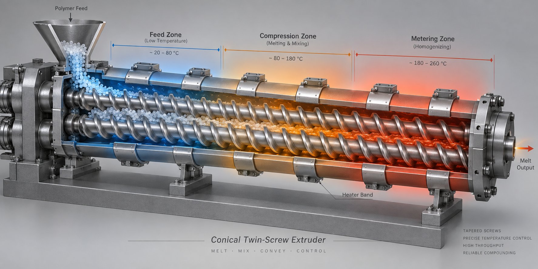
Picture the barrel of a conical twin-screw extruder divided into three functional regions, each with a distinct thermal role in the pipe extrusion process. These zones do not simply "heat up the plastic" — they orchestrate a carefully staged transformation from free-flowing powder to a fully homogenized, pressurized melt.
Feed zone: This is where the dry blend enters the barrel from the hopper. The temperature here must remain relatively cool — deliberately kept below the compound's melting point. Why? Because the PVC powder needs to be conveyed forward by the screw flights as a solid, not stick to metal surfaces as a partially molten mass. If the feed zone runs too hot, the compound softens prematurely and bridges across the screw channels, starving downstream zones of material. You'll recognize this problem by fluctuating motor current and inconsistent pipe wall thickness. A properly managed feed zone temperature ensures steady, predictable material intake — the first condition for uniform output.
Compression zone: Here the real work begins. The screw geometry narrows, compressing the material while barrel heaters progressively ramp temperature upward. Frictional heat from mechanical shear adds to the external heating, and together they begin plasticizing the PVC compound. Air trapped between powder particles is squeezed out and vented. The compression zone must achieve enough heat and pressure to transform the dry blend into a coherent, semi-molten mass — but not so much shear heat that it overshoots the compound's safe processing ceiling. Balancing external heater settings against the frictional heat generated by screw rotation is one of the most skill-dependent aspects of running pvc extrusion equipment.
Metering zone: By the time compound reaches the metering section, it should be fully plasticized. This zone's job is homogenization — ensuring that temperature, viscosity, and pressure are uniform across the entire melt cross-section before it enters the die adapter. Temperatures here are set at or slightly above the compound's optimal melt point. The metering zone acts as a quality gate: if it receives poorly plasticized material from an underperforming compression zone, no amount of metering-zone heat can fix the inconsistency. Conversely, if upstream zones push material too hot, the metering section has no way to cool it back down without external barrel cooling fans.
The typical temperature progression follows a deliberate gradient — lowest at the feed throat and stepping up through each successive zone. Exact setpoints vary by compound formulation, screw geometry, and equipment manufacturer, so you should always reference the machinery supplier's recommended profiles as a starting baseline and fine-tune from there using melt temperature readings and product quality feedback. What matters most is the relative zone-to-zone progression: a controlled, predictable ramp that gives the PVC compound exactly the thermal energy it needs at each stage, no more and no less.
Die and Adapter Temperature Control
The adapter connects the extruder barrel to the pipe die, and the die itself shapes the melt into a hollow tube. Temperature management across these two components has an outsized effect on finished pipe quality — specifically surface finish, dimensional stability, and the risk of melt fracture.
Die temperature directly controls the behavior of the melt as it exits through the annular gap. Set the die too cool and the melt's viscosity rises, increasing shear stress at the die lips. The result? A rough, "sharkskin" texture on the pipe surface, or in more severe cases, full melt fracture that produces visible distortions. Raise the die temperature appropriately and the melt flows more smoothly through the exit, producing a glossy, defect-free surface.
However, pushing die temperatures too high introduces a different set of problems. Overly hot melt exiting the die is softer and more difficult to calibrate accurately in the vacuum sizing tank downstream. It also increases the risk of thermal degradation right at the die surface — exactly where stagnant flow zones or "dead spots" tend to form. Material that lingers in a poorly designed die channel at elevated temperature will degrade, producing brown streaks or carbonized particles that embed in the pipe wall.
Uniform heat distribution across the die face is equally critical. Imagine a die where the top runs 5 °C hotter than the bottom. The melt on the hotter side flows faster and exits with a slightly thinner wall, while the cooler side produces a thicker wall. That asymmetry carries through calibration and cooling, resulting in a pipe with measurably uneven wall thickness — a defect that can cause the pipe to fail pressure testing or, worse, fail in the field. Modern die heads use multiple independently controlled heater bands and strategically placed thermocouples to maintain temperature uniformity within tight tolerances across the entire annular cross-section.
The adapter zone deserves equal scrutiny. Because the melt transitions from the barrel's circular cross-section to the die's annular shape within the adapter, any temperature imbalance here disrupts flow symmetry before the melt even reaches the die land. Consistent adapter heating ensures the melt arrives at the die inlet with uniform viscosity around its full circumference.
Why PVC Is Uniquely Sensitive to Thermal Control
Every thermoplastic has a processing window — the temperature range between the point where the material melts sufficiently for shaping and the point where it begins to degrade. For most common polymers like polyethylene, polypropylene, or ABS, this window is comfortably wide, giving operators a generous margin for adjustment. PVC is a different story entirely.
PVC has one of the narrowest processing windows of any commercial thermoplastic. Its degradation temperature sits dangerously close to its melt processing temperature, making precise zone-by-zone thermal control not merely recommended but absolutely non-negotiable for producing quality pipe.
When PVC overheats — even locally, even briefly — the polymer chains begin to break down through a process called dehydrochlorination. This reaction releases hydrogen chloride (HCl) gas, which is both corrosive and toxic. HCl attacks metal barrel and screw surfaces, accelerating wear and increasing maintenance costs. It contaminates the pipe itself, introducing discoloration, weakened mechanical properties, and potentially making the pipe unsuitable for potable water applications. And the reaction is autocatalytic: once degradation starts in a localized hot spot, the released HCl actually accelerates further degradation of surrounding material, creating a cascading failure that can ruin an entire production run before operators notice visible signs on the pipe surface.
This is precisely why the pvc extrusion line relies on multi-zone heating with independently controlled barrel, adapter, and die zones, supplemented by active cooling systems — typically fans or blowers mounted on the barrel — that counteract excess shear heat. Operators cannot simply set barrel heaters and walk away. Real-time melt temperature monitoring, regular thermocouple calibration, and careful attention to screw speed are all essential. Higher screw RPM generates more frictional heat, which can push melt temperatures above safe limits even when heater setpoints look correct on the control panel.
Stabilizers in the PVC formulation provide a buffer — they absorb HCl and delay the onset of degradation — but they are a finite resource within each batch of compound. Relying on stabilizer chemistry to compensate for sloppy temperature control is a losing strategy. Stabilizers extend the safe processing window; they do not replace thermal management discipline.
For any manufacturer running a pvc water pipe extrusion line, the temperature profile is not just one variable among many — it is the variable that determines whether you produce sellable pipe or scrap. And the component most responsible for translating that temperature profile into consistent melt quality is the screw and barrel assembly itself, where heat transfer, shear generation, and material conveyance all converge.
How the Screw and Barrel Define Your Extrusion Output Quality
Temperature profiles only matter if the hardware translating them into melt quality is up to the task. Every watt of heater energy, every degree of shear-generated heat, and every gram of PVC compound passes through one critical interface: the screw and barrel. These two components do more to determine the consistency, efficiency, and quality ceiling of a pvc pipe extruder than any other single element on the line. When they perform well, the rest of the system has a fighting chance. When they degrade, problems cascade everywhere.
Why the Screw and Barrel Are the Heart of the Extruder
The screw and barrel assembly performs four overlapping functions simultaneously — conveying, compressing, plasticizing, and homogenizing the PVC compound. Each function maps to a physical zone along the barrel length, and each depends on precise geometry: flight depth, pitch angle, compression ratio, and the clearance between screw flights and barrel wall.
For rigid PVC pipe production, conical twin-screw extruders have become the dominant platform. Why conical rather than parallel? The tapered geometry provides a larger screw diameter at the feed end and a smaller diameter at the discharge, delivering high torque where the material needs maximum conveying force and progressively lower shear where the fully plasticized melt needs gentle handling. This arrangement directly matches PVC's processing demands — aggressive enough early on to compact and plasticize the powder, restrained enough at the metering end to avoid the thermal degradation discussed in the previous section.
Conical twin-screw designs are fully intermeshing and counter-rotating, functioning as positive displacement pumps that are independent of frictional criterion. The self-wiping action of the intermeshing flights minimizes material stagnation — a critical advantage for thermally sensitive PVC that degrades when it lingers in dead spots. This same principle applies across rigid PVC applications: the conical twin-screw architecture serves not only pipe extruders but also pvc profile extrusion and board production, where consistent melt delivery is equally essential.
The smaller metering-zone diameter offers another practical benefit: reduced axial force on the screws. Lower axial loads translate to less mechanical stress on thrust bearings and gearbox components, contributing to longer equipment life. Additionally, the lower shear rate in the metering section means less unwanted temperature rise, reduced die swell, and a calmer, more uniform melt entering the die — exactly the conditions you need for precise wall thickness control in water pipe production.
How Screw Wear Degrades Pipe Quality Over Time
Even the best-engineered screw and barrel set is a wear item. Every hour of operation, abrasive fillers like calcium carbonate grind against metal surfaces, corrosive byproducts from PVC processing attack the barrel lining, and the relentless mechanical forces gradually widen the gap between screw flight tips and barrel bore. This wear is slow — often imperceptible on a daily basis — but its cumulative effect on pipe quality is significant.
Here is why that clearance gap matters so much: conical twin-screw pvc extruders rely on tight intermeshing geometry to function as positive displacement devices. As the gap increases due to wear, the output also decreases because material slips backward through widened clearances instead of being pushed forward. The consequences ripple through the entire production process:
- Declining output at the same RPM — the most obvious early symptom. You'll notice production rates dropping even though screw speed, temperature settings, and formulation remain unchanged.
- Rising melt temperature without parameter changes — worn clearances force the motor to work harder, generating excess frictional heat that pushes melt temperatures above safe limits. This is particularly dangerous with PVC's narrow processing window.
- Unstable melt pressure fluctuations — a worn screw barrel cannot generate consistent shear and compression, leading to pressure swings that show up as wall thickness variation in the finished pipe.
- Poor plasticizing and incomplete melting — increased clearance allows powder particles to bypass the compression zone without fully melting, producing unmelted specks, rough surfaces, and weakened pipe walls.
- Increased energy consumption — the motor draws more current to compensate for lost pumping efficiency, driving up electricity costs per kilogram of pipe produced.
- Visible wear marks on screws — scoring, pitting, or measurable reduction in flight height are physical confirmation of what the production data already suggests.
Many operators initially respond to these symptoms by adjusting process parameters — raising temperatures, increasing screw speed, or tightening vacuum calibration. These adjustments may mask the problem temporarily, but they are treating symptoms rather than the root cause. A plastic pipe extruder running with worn screws and barrel is fighting physics, and the compromises compound over time. At some point, the only real fix is replacement.
Selecting a Reliable Screw and Barrel Supplier
Replacing the screw and barrel set is one of the most consequential maintenance decisions a PVC pipe manufacturer faces. The replacement components must match the original equipment's geometry precisely — or intentionally improve upon it — while being manufactured from materials that resist the specific wear mechanisms present in PVC processing: abrasion from fillers, corrosion from HCl, and adhesive wear from metal-to-metal contact under pressure.
When evaluating suppliers, you'll want to consider several factors beyond just price:
- Material expertise: Does the supplier understand the metallurgy required for PVC applications — nitrided steel, bimetallic linings, or specialized alloys for high-filler formulations?
- Dimensional precision: Screw and barrel tolerances are measured in hundredths of a millimeter. Manufacturing accuracy directly determines how well the replacement set restores original performance.
- Application knowledge: A supplier who understands the differences between pipe and profile extrusion equipment requirements can recommend geometry optimizations that a generic manufacturer might miss.
- Lead time and availability: Screw and barrel wear does not wait for convenient scheduling. A supplier with responsive manufacturing and stock programs minimizes production downtime during replacement.
One specialist worth evaluating is NANHAIYA, which focuses specifically on conical twin screw barrels for PVC extrusion applications. NANHAIYA serves manufacturers across PVC pipe, pvc profile extrusion, PVC board, foam board, and WPC extrusion segments, providing both custom-engineered and replacement conical twin screw barrels designed for stable plasticizing performance. For pipe producers who want an independent, qualified component source — separate from their main line OEM — this type of specialized supplier can offer both technical depth and supply chain flexibility that generalist vendors often cannot match.
Whether you source replacements from the original equipment manufacturer or from a specialist like NANHAIYA, the key is treating screw and barrel maintenance as a proactive quality investment rather than an emergency repair. Monitoring output trends, melt pressure stability, and energy consumption month over month gives you the data to schedule replacements before worn components begin producing defective pipe — which is exactly the kind of defect analysis the next section addresses in practical, floor-ready detail.
Troubleshooting Common PVC Water Pipe Extrusion Defects
Worn screws and barrels are one source of defective pipe — but they are far from the only one. Across a full pvc water pipe extrusion line, dozens of variables interact simultaneously, and a single misstep at any station can produce pipe that fails dimensional checks, pressure tests, or visual inspection. The challenge on the production floor is not just spotting a defect — it is tracing it back to the right root cause fast enough to minimize scrap.
This section maps the most common defects in extruded pipe manufacturing to their likely origins and corrective actions. Bookmark it, print it, tape it to the control panel — it is designed to be used in real time.
Wall Thickness Variation and Ovality
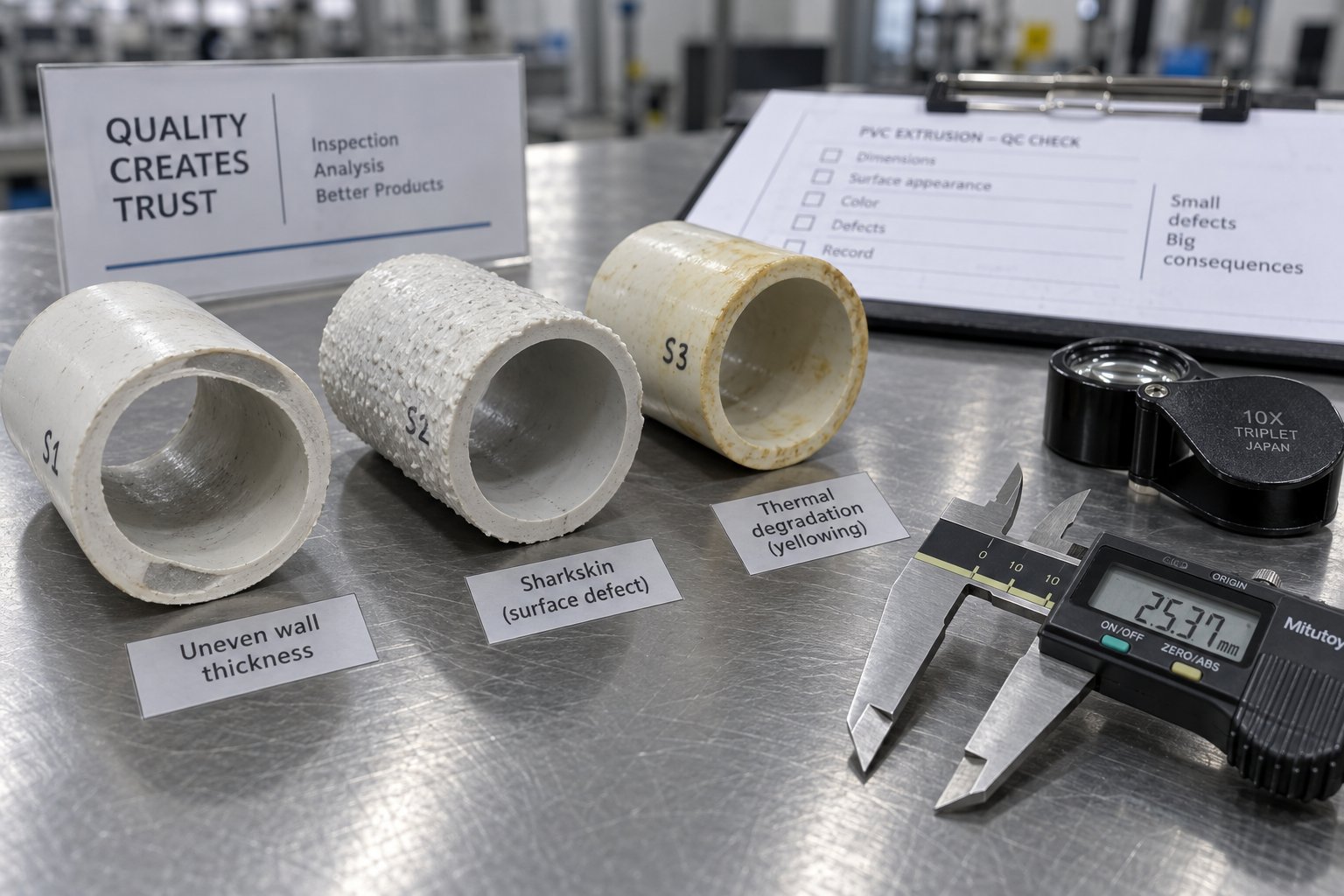
Uneven wall thickness — where one side of the pipe is measurably thicker than the opposite side — is one of the most critical quality failures in extruded plastic pipe production. It directly undermines the pipe's pressure-bearing capacity, because the thinnest point becomes the weakest link in the entire circumference. Ovality, where the pipe cross-section becomes elliptical rather than round, creates a related but distinct problem: joints and fittings cannot seal properly against an out-of-round pipe.
What makes these defects frustrating is that multiple independent causes can produce nearly identical symptoms. Consider the possibilities:
- Off-center die adjustment: If the die and mandrel are not perfectly concentric, the annular gap varies around the circumference, producing a pipe that is inherently thicker on one side from the moment the melt exits the die. The fix is meticulous die centering using the adjustment bolts on the die head, verified with a dial indicator or by measuring short pipe samples immediately after startup.
- Inconsistent haul-off speed: When the caterpillar haul-off surges or slows, the pipe stretches unevenly. You'll notice wall thickness fluctuating along the pipe length rather than around its circumference — a useful diagnostic clue that distinguishes haul-off problems from die alignment issues. Checking drive belt tension, servo motor response, and track pad condition usually resolves the instability.
- Vacuum calibration pressure imbalance: Insufficient or uneven vacuum pressure in the calibration tank fails to press the soft extrusion pipe uniformly against the sizing sleeve. One side pulls outward more than the other, creating both thickness variation and ovality in a single defect. Cleaning clogged spray nozzles and verifying vacuum pump stability are the first corrective steps.
- Uneven die temperature: Even a 5 degree Celsius discrepancy across the die face causes the melt to flow faster on the hotter side and slower on the cooler side — producing asymmetric wall thickness that no amount of downstream calibration can fully correct. Checking heater band continuity and thermocouple accuracy isolates the source.
- Worn screw and barrel allowing melt surging: As discussed in the previous section, worn clearances create pressure fluctuations that the die translates into periodic wall thickness swings. If the variation shows a rhythmic pattern that correlates with screw rotation, screw and barrel wear is the likely culprit.
For ovality specifically, non-uniform cooling deserves separate attention. Uneven water spray patterns — caused by partially blocked nozzles, inconsistent water temperature between the top and bottom of the cooling tank, or insufficient pipe support between rollers — allow the still-warm pipe to deform under gravity or residual stress before it fully solidifies. A complete centerline alignment check from die head through cooling tanks, haul-off, and cutter should be standard procedure whenever ovality appears.
Surface Defects Including Shark Skin and Melt Fracture
Run your hand along the outside of a freshly extruded pipe. It should feel smooth and glossy. If instead you feel fine, regular ridges — almost like the texture of sharkskin leather — you are looking at a classic shear-induced surface defect. And if the surface shows more severe waviness, distortion, or gross irregularity, the problem has escalated to full melt fracture.
Both defects originate at the same place: the die exit. As the PVC melt flows through the narrow annular gap and emerges into open air, the outer layer of the melt experiences intense shear stress against the die wall. When that stress exceeds the melt's elastic limit, the surface layer fractures rather than flowing smoothly. Shark skin is the mild form — a surface-only disturbance. Melt fracture is the severe form, where the entire melt stream becomes unstable.
The root causes typically come down to a handful of controllable variables:
- Excessive extrusion speed: Higher output rates push more material through the die per unit time, increasing shear stress at the die lips. The most direct corrective action is reducing screw RPM or line speed — though this obviously impacts throughput, so it should be paired with other adjustments rather than accepted as a permanent fix.
- Incorrect die temperature: A die running too cool raises melt viscosity at the exit, increasing shear stress. Gradually raising die temperature often eliminates shark skin without requiring a speed reduction. However, pushing die temperature too high risks degradation in stagnant flow zones, so adjustments should be incremental and monitored.
- Inadequate lubrication in the PVC formulation: External lubricants in the PVC compound reduce friction between the melt and die metal surfaces. If the formulation is under-lubricated — or if lubricant was poorly dispersed during the mixing stage — surface defects appear even at moderate extrusion speeds. Reviewing the formulation's lubrication package with a materials specialist and verifying mixer discharge temperatures can resolve formulation-related surface issues.
- Worn or damaged die surfaces: Scratches, nicks, or buildup of degraded material on the die land or mandrel tip physically disrupt the melt flow, creating longitudinal lines or streaks on the pipe surface. Regular die cleaning, polishing, and inspection should be part of every planned maintenance cycle.
A practical diagnostic tip: shark skin affects only the outermost layer and appears as a uniform, repeating texture. If you see random rough patches, isolated pits, or localized rough streaks instead, the cause is more likely moisture in the raw material, incomplete plasticizing, or contamination — not shear-related surface fracture. Distinguishing between these patterns saves significant troubleshooting time on the floor.
Discoloration and Thermal Degradation Signs
Yellowing, brown streaks, or dark specks in an extruded pipe are never cosmetic issues — they are physical evidence that PVC has degraded. As covered earlier, PVC decomposition releases hydrogen chloride gas, which corrodes equipment and compromises pipe integrity. But when discoloration appears on the production line, the immediate question is not what happened — it is where in the process it happened.
Three primary sources account for the vast majority of thermal degradation defects in extrusion pipe production:
- Excessive barrel zone temperatures: If the overall pipe shows a uniform yellow tint rather than localized streaks, the barrel temperature profile is likely too aggressive. The compound is overheating throughout the entire melt path. Corrective action starts with reviewing and reducing barrel zone setpoints — particularly in the compression and metering zones — and verifying that cooling fans are functioning and thermocouple readings are accurate.
- Dead spots in the die or adapter: Brown or dark streaks that appear intermittently, often as thin lines running along the pipe length, typically point to stagnant flow zones where material lingers at elevated temperature. These dead spots commonly form at sharp transitions in flow channels, at poorly machined adapter connections, or where degraded buildup narrows the flow path. Disassembling and cleaning the die head and adapter — and inspecting for design flaws or damage that create stagnation zones — is the corrective path.
- Prolonged residence time: Running the extruder at very low output speeds — during startup, shutdown, or extended production pauses — keeps compound inside the hot barrel far longer than the formulation's stabilizer package can protect it. Material that sits in the barrel too long degrades in place, and when production resumes, degraded material flushes through as discolored streaks or specks. The solution is to minimize idle time at operating temperature, purge the barrel thoroughly before shutdowns, and avoid running at extremely low RPM for extended periods.
How do you determine whether the issue is barrel-side, die-side, or formulation-related? A simple diagnostic approach: collect a sample of the melt directly at the extruder discharge — before it enters the adapter and die — and inspect it for discoloration. If the melt is already discolored at this point, the problem originates upstream in the barrel zones or in the raw material itself. If the melt looks clean but the finished pipe shows degradation marks, the adapter or die is the culprit. And if discoloration appears only in certain batches or after formulation changes, the stabilizer package or mixer performance should be investigated first.
Defect-Cause-Solution Quick Reference Matrix
The table below consolidates the most common defects encountered when you extrude pipe from rigid PVC, along with their probable root causes and practical corrective actions. Use it as a rapid diagnostic tool — identify the defect in the left column, then work through the corresponding causes and solutions.
| Defect | Possible Root Cause | Corrective Action |
|---|---|---|
| Uneven wall thickness | Die/mandrel misalignment | Re-center die using adjustment bolts; verify with short-sample measurement |
| Uneven die temperature | Check heater bands and thermocouples; ensure uniform temperature across die face | |
| Worn screw and barrel (melt surging) | Monitor melt pressure trends; schedule screw/barrel replacement when fluctuations exceed tolerance | |
| Inconsistent haul-off speed | Inspect drive system, belt tension, and servo response; recalibrate speed control | |
| Ovality | Insufficient vacuum in calibration tank | Verify vacuum pump performance; check for air leaks in tank seals |
| Non-uniform cooling spray pattern | Clean or replace clogged nozzles; verify water temperature consistency around pipe circumference | |
| Haul-off misalignment or excessive clamping force | Re-align haul-off to extrusion centerline; reduce clamping pressure to minimum effective grip | |
| Inadequate pipe support between stations | Add or adjust roller supports to prevent sagging of warm pipe | |
| Shark skin (fine surface roughness) | Excessive shear stress at die exit | Reduce extrusion speed; increase die temperature incrementally; review external lubricant levels in formulation |
| Melt fracture (severe surface distortion) | Output speed exceeds die design capacity | Reduce screw RPM; consider a die with a longer land length or wider gap for the target pipe size |
| Die temperature too low | Raise die zone temperature in small increments while monitoring surface quality | |
| Surface lines or streaks | Scratched or contaminated die/mandrel surfaces | Disassemble, clean, and polish die and mandrel; replace damaged components |
| Yellowing (uniform) | Barrel temperatures set too high overall | Reduce barrel zone setpoints; verify thermocouple accuracy and cooling fan operation |
| Brown streaks or dark specks | Dead spots in die or adapter causing localized overheating | Disassemble and clean adapter and die; inspect for flow channel obstructions or design flaws |
| Prolonged residence time during low-speed operation or pauses | Minimize idle time at temperature; purge barrel before shutdowns; avoid extended low-RPM operation | |
| Rough inner surface | Damaged or contaminated mandrel | Inspect, clean, and polish mandrel surface; replace if worn or pitted |
| Incomplete plasticizing (underheated melt) | Review barrel temperature profile; check for worn screw flights reducing compression efficiency | |
| Bubbles or voids in pipe wall | Moisture in raw material | Verify mixer discharge temperature; check raw material storage conditions; ensure vacuum venting is functional |
| Excessive processing temperature causing PVC decomposition | Reduce barrel temperatures; review stabilizer levels in formulation |
One pattern runs through nearly every row of this matrix: most defects in extruded plastic pipe production are not caused by a single factor acting alone. A pipe showing both wall thickness variation and surface roughness, for instance, may be dealing with a worn screw and an under-lubricated formulation simultaneously. Effective troubleshooting means resisting the urge to stop at the first plausible explanation and instead verifying each variable systematically — from raw material quality through barrel conditions, die alignment, and downstream settings.
Keeping this kind of structured diagnostic approach on the production floor is what separates operations that consistently produce specification-grade extruded pipe from those that spend their days chasing intermittent defects. But diagnosing problems is only half the equation — the other half is knowing what to look for in the equipment specifications themselves, so that the line you purchase or upgrade is engineered to minimize these issues from the start.
Key Technical Specifications Every Buyer Should Understand
Equipment spec sheets are packed with numbers — screw diameters, L/D ratios, kilowatt ratings, output capacities. If you are evaluating a plastic pipe extrusion line for the first time, these figures can feel like a foreign language. But each number describes a real-world production capability, and understanding what it means saves you from buying a line that is either underpowered for your targets or unnecessarily oversized for your market. Here is how to read the specs that matter most.
Screw Diameter, L/D Ratio, and What They Mean for Output
On any conical twin-screw tubing extruder, the screw diameter is the single biggest indicator of throughput capacity. Common conical twin-screw sizes for PVC water pipe production range from roughly 51 mm up to 92 mm or larger at the feed end. A larger diameter means more material conveyed per revolution, which translates directly to higher maximum output in kilograms per hour.
To put real numbers to this: a 65 mm class extruder typically delivers 450-500 kg/h, while a 110 mm class machine can push output to 1,650 kg/h under optimal conditions. That is more than a threefold increase in capacity — driven primarily by screw geometry.
The L/D ratio — the length of the screw relative to its diameter — affects how thoroughly the PVC compound is mixed and plasticized during its journey through the barrel. A higher L/D ratio gives the material more residence time and more exposure to shear and heat, generally improving melt homogeneity. The tradeoff? Longer barrels cost more, consume more energy, and require more floor space. For most PVC water pipe applications, an L/D ratio in the range of 22:1 to 28:1 provides a practical balance between plasticizing quality and machine economics. Stepping beyond that range is typically justified only for specialty formulations or very high-filler compounds that demand extra mixing.
Motor Power, Output Capacity, and Line Speed
Motor power — expressed in kilowatts — determines how much mechanical energy the extruder can deliver to the screws. More power enables higher screw speeds and greater throughput, but the relationship is not purely linear. A 75 kW motor paired with a well-designed screw set can achieve 800 kg/h on pipes in the 50-110 mm range, while a 90 kW motor handling larger 200-630 mm pipes may only reach 700-800 kg/h because the thicker walls and larger diameters demand more energy per kilogram of output.
Line speed — measured in meters per minute — tells you how fast the finished pipe moves through the downstream equipment. Sounds like higher is always better? Not quite. Maximum line speed must be matched to cooling capacity and pipe wall thickness. A thin-walled 50 mm pipe can travel at 25 m/min because it cools quickly. A thick-walled 400 mm pipe might run at just 8 m/min because the cooling tanks need far more time to solidify the substantial wall section. Buying a high-speed plastic extrusion line without proportionally sized cooling capacity is like buying a sports car with no brakes — impressive on paper, unusable in practice.
Pipe Diameter Range and Wall Thickness Capability
Every plastic pipe extrusion line is rated for a specific pipe diameter range. Some lines cover a narrow band — say 50 to 160 mm — while others span a broader window like 110 to 400 mm. The extrusion tube process itself can accommodate a wide range of sizes through die changes and downstream adjustments, but pushing a line to the extremes of its rated range typically reduces efficiency. A line rated for 50-200 mm pipes will produce 75 mm pipe at peak performance but may struggle with surface quality or cooling uniformity when attempting 200 mm pipe at full speed.
Wall thickness capability is equally important and often overlooked. The plastic tubing extrusion process for a pressure-rated water pipe demands precise wall thickness control — and the achievable range depends on die design, vacuum calibration capacity, and cooling infrastructure. If your product mix includes both SDR 41 (thin-wall, low-pressure) and SDR 17 (thick-wall, high-pressure) pipes, verify that the line can handle both extremes without excessive changeover or quality compromise.
| Specification | What It Measures | Why It Matters to Buyers | Typical Range |
|---|---|---|---|
| Screw Diameter (feed end) | Physical size of the conical screws at the larger, inlet end | Determines maximum throughput capacity; larger diameter enables higher output | 51 mm to 92 mm+ |
| L/D Ratio | Screw length relative to its diameter | Affects plasticizing quality and melt homogeneity; higher ratios improve mixing but increase cost | 22:1 to 28:1 |
| Motor Power | Maximum energy the drive delivers to the screws (kW) | Limits maximum output rate and determines energy cost per kilogram; must match target throughput | 55 kW to 110 kW+ |
| Output Capacity | Maximum material throughput in kg/h | Defines production volume ceiling; must align with your daily or annual tonnage targets | 450 to 1,650 kg/h |
| Maximum Line Speed | Speed of pipe movement through downstream stations (m/min) | Must be matched to cooling capacity and wall thickness; overstating speed without cooling support wastes investment | 8 to 25 m/min |
| Pipe Diameter Range | Minimum and maximum pipe OD producible with die changes | Determines product flexibility; operating at range extremes may reduce efficiency | 16-110 mm (small line) to 200-630 mm (large line) |
| Wall Thickness Range | Minimum and maximum achievable wall thickness | Governs which pressure classes (SDR ratings) the line can produce; critical for meeting target standards | Application-dependent; verified per die and calibrator setup |
One principle ties all these specifications together: no single number tells the whole story. A line with an impressive output capacity but inadequate cooling length will never reach its rated speed. A powerful motor paired with a small-diameter screw set wastes energy. The extrusion of pipes at production scale requires every specification to work in concert — screw geometry, motor power, cooling infrastructure, and downstream handling all sized proportionally to the target pipe range. When evaluating quotations, resist the temptation to compare individual specs in isolation. Instead, ask how the complete system performs on the specific pipe sizes, wall thicknesses, and daily output volumes your business actually requires.
Specifications tell you what a line can do. But whether it actually delivers depends on who built it, who supports it, and who stands behind it when something goes wrong — which makes supplier evaluation just as important as technical evaluation.
How to Evaluate and Select the Right Extrusion Line Supplier
Specifications describe a machine's potential. Supplier quality determines whether that potential translates into years of profitable, trouble-free production — or into a costly cycle of downtime, finger-pointing, and regret. Selecting the right partner for a pvc pipe production line is a decision that outlasts the purchase order by a decade or more, and it deserves a framework as rigorous as the technical evaluation itself.
Technical Capability and Reference Checking
Every extrusion line supplier will claim their equipment meets your needs. Your job is to verify those claims with evidence, not brochures. Start with specifics: has the supplier delivered lines producing PVC water pipe to the exact standards your market requires — whether that is ASTM D1785, ISO 1452, or a regional specification? A supplier experienced in plastic pipe extrusion for general drainage applications may not have the process expertise to deliver a line that consistently meets potable-water pressure pipe tolerances.
Reference installations are your strongest verification tool. Ask for a list of customers running similar pipe diameter ranges, wall thicknesses, and material formulations on the same model line you are considering. Then go further — request production data from those reference sites: actual output rates, dimensional consistency records, and reject percentages. A confident supplier will facilitate direct contact with reference customers or even arrange a site visit. A supplier who deflects these requests is waving a red flag.
Independent inspection adds another layer of assurance. If you cannot visit the factory in person, engage a third-party inspection firm to witness a factory acceptance test (FAT) on your line before shipment. This step catches assembly quality issues, electrical wiring deficiencies, and component substitutions that no amount of specification review on paper can reveal. As one industry checklist emphasizes, two quotations using identical language can deliver vastly different scope and component quality — making physical verification essential.
Commissioning, Training, and After-Sales Support
A reliable pp pvc pipe extrusion line supplier does not consider the sale complete when the container leaves the factory. The real partnership begins at commissioning — and this is where many buyers discover whether they chose a manufacturer or merely a machine seller.
On-site commissioning should include installation supervision, mechanical and electrical alignment verification, process parameter setup for your specific PVC formulation, and a production trial that demonstrates the line meets its rated output and quality targets with your actual raw materials. Clarify exactly what "commissioning included" means in the quotation: how many engineer-days are covered, who pays for travel and accommodation, and what constitutes a successful acceptance test. Vague language here leads to disputes later.
Operator training is equally non-negotiable. Even experienced extrusion operators need to learn the specific control logic, alarm systems, and maintenance procedures of a new line. Training should cover startup and shutdown sequences, temperature profile adjustment, die changeover procedures, and basic troubleshooting — at minimum. Some suppliers offer tiered training programs, with initial operator-level instruction during commissioning and advanced process optimization training after the team has accumulated production experience.
After-sales support separates serious manufacturers from transactional vendors. Key questions to pin down before signing:
- What is the warranty duration, and which components are covered?
- Is remote diagnostic support available — can the supplier's engineers access the line's PLC remotely to troubleshoot control issues?
- What are typical spare parts lead times for critical items like heater bands, thermocouples, drive belts, and vacuum pump components?
- Does the supplier maintain regional service centers or local partners, or must every service visit originate from the home factory?
Spare parts availability is particularly important for plastic tube extrusion equipment that runs around the clock. A two-week wait for a replacement temperature controller or haul-off motor can cost more in lost production than the part itself. Evaluate whether the supplier stocks fast-moving spares or operates strictly on a make-to-order basis.
Building a Reliable Component Supply Chain
Here is a strategic point most buyers overlook: your extrusion line supplier is not the only vendor relationship that matters. Key wear components — especially the conical twin screw and barrel set — will need replacement during the line's service life, often multiple times. Relying solely on the original equipment manufacturer for these replacements creates a single point of dependency that can extend lead times, limit negotiating leverage, and leave you vulnerable if the OEM discontinues support for older models.
Building an independent supply chain for critical wear parts is a practical risk-mitigation strategy. Specialized component manufacturers often deliver faster turnaround, competitive pricing, and application-specific expertise that broad-line OEMs cannot always match. NANHAIYA, for example, focuses specifically on conical twin screw barrels for PVC extrusion — serving pipe, profile, board, foam board, and WPC manufacturers with custom and replacement barrel sets engineered for stable plasticizing performance. Partnering with a dedicated component supplier like this, independently of your main line OEM, gives you a second qualified source that can reduce downtime risk and improve long-term production economics through competitive sourcing.
Whether you choose plastic tube extrusion equipment from a European, Chinese, or Indian line builder, the evaluation checklist below applies universally. Use it as a structured scoring tool when comparing finalists:
- Proven PVC water pipe track record — documented reference installations producing to your target standards
- Verifiable production data — output rates, dimensional records, and reject percentages from reference sites
- Factory acceptance test — witnessed FAT with your pipe specifications before shipment
- Clearly defined commissioning scope — engineer-days, acceptance criteria, and cost boundaries in writing
- Comprehensive operator training — covering startup, operation, changeover, and basic troubleshooting
- Warranty terms in detail — duration, covered components, exclusions, and claim procedures
- Remote diagnostic capability — PLC-level remote access for rapid troubleshooting support
- Spare parts lead time commitments — documented delivery times for critical consumable and wear items
- Independent wear-component sourcing — qualified alternative suppliers for screw and barrel sets and other high-wear parts
- Total cost of ownership analysis — energy consumption, material efficiency, maintenance projections, and expected uptime factored alongside purchase price
The lowest quotation price is rarely the lowest total cost. A thorough evaluation — covering technical capability, after-sales infrastructure, and component supply chain resilience — protects your investment far more effectively than negotiating a few percentage points off the purchase price. The right extrusion line, from the right supplier, supported by the right component partners, is a production asset that delivers returns for decades.
Frequently Asked Questions About PVC Water Pipe Extrusion Lines
1. What are the main components of a PVC water pipe extrusion line?
A complete PVC water pipe extrusion line consists of a raw material feeding system, a conical twin-screw or single-screw extruder, a pipe die head with adapter, a vacuum calibration tank for sizing, spray cooling tanks, a caterpillar or belt haul-off unit, a planetary or chipless saw cutter, and finishing stations such as a belling machine, inkjet marking system, and automatic pipe stacker. Each station performs a specific transformation — from melting and shaping PVC compound to cooling, cutting, and finishing — and must be precisely synchronized to produce dimensionally accurate, defect-free water pipe.
2. What is the difference between UPVC, CPVC, and PVC-O pipe extrusion?
UPVC is the standard material for cold-water supply pipes, processed on conical twin-screw lines at barrel temperatures of 160-190 degrees Celsius. CPVC is used for hot-water applications and requires processing temperatures roughly 10-20 degrees Celsius higher, along with modified screw geometry and extended cooling tanks. PVC-O is a biaxially oriented variant that adds an inline expansion stage after initial extrusion, reheating the pipe to 85-100 degrees Celsius and stretching it radially to dramatically improve impact resistance and pressure ratings. Each material demands a distinct line configuration, so equipment optimized for one type cannot simply switch to another without hardware and process changes.
3. Why is temperature control so critical in PVC pipe extrusion?
PVC has one of the narrowest processing windows among commercial thermoplastics — its degradation temperature sits very close to its melt processing temperature. If temperatures run too low, the compound remains poorly plasticized, producing rough surfaces and weak weld lines. If temperatures exceed safe limits even briefly, the PVC undergoes dehydrochlorination, releasing corrosive hydrogen chloride gas that damages equipment, contaminates the pipe, and triggers a cascading degradation reaction. Multi-zone barrel heating with independent control, active cooling fans, and real-time melt temperature monitoring are all essential to stay within this narrow safe window.
4. How do I know when the screw and barrel need replacement on my PVC extruder?
Key warning signs include declining output at the same screw RPM, rising melt temperature without any parameter changes, unstable melt pressure fluctuations that cause wall thickness variation, incomplete plasticizing visible as rough pipe surfaces or unmelted specks, increased motor energy consumption, and visible scoring or pitting on the screw flights. Monitoring output trends and melt pressure stability monthly helps you schedule proactive replacements. Specialized suppliers like NANHAIYA (nhyscrews.com) offer custom and replacement conical twin screw barrels engineered specifically for PVC extrusion, providing an independent sourcing option separate from your main line OEM.
5. What specifications should I prioritize when buying a PVC pipe extrusion line?
Focus on five interconnected specifications: screw diameter (51-92 mm range for conical twin-screw, which determines maximum throughput), L/D ratio (typically 22:1 to 28:1 for PVC, affecting plasticizing quality), motor power in kW (which limits output rate), pipe diameter range (verify the line performs well across your full product mix, not just at the midpoint), and cooling capacity relative to maximum line speed. No single spec tells the whole story — a high-output extruder paired with undersized cooling tanks will never reach rated speed. Always evaluate how the complete system performs on your specific pipe sizes, wall thicknesses, and target daily volumes.
Written by
Nanhaiya Technical Team
Zhoushan Nanhaiya Plastic Machinery Co., Ltd.
The Nanhaiya technical team supports screw and barrel manufacturing projects through application review, technical communication, custom manufacturing coordination, and production and quality control.
Discuss Your Application
Related Articles
More insights on screw barrel technology and plastics processing.

Extruder Machine Decoded: From Raw Pellet To Finished Product
Oct 6, 2026
Learn how an extruder machine works, compare single-screw vs. twin-screw types, and get expert guidance on specs, troubleshooting, and selection.
Read Article
PE Pipe Making Machine Decoded: From Raw Resin to Flawless Pipe
Oct 4, 2026
Learn how a PE pipe making machine works, from resin to finished pipe. Covers components, material grades, automation, troubleshooting, and buyer selection tips.
Read Article
PVC Profile Making Machine Decoded: From Raw Resin To Profit
Oct 3, 2026
Learn how a PVC profile making machine works — extrusion process steps, key technical parameters, die design, calibration methods, maintenance, and total cost of ownership.
Read ArticleLooking for something else?
Search by material, symptom or product and jump straight to the relevant page.
These are navigation suggestions based on keyword matching — not a quotation, not a delivery commitment, and not a substitute for engineering review. Final specification is confirmed by our engineers against your drawings and processed material.
Need help with screw barrel selection?
Share your machine model, processed material and application. Our team can help with pricing and technical support.