

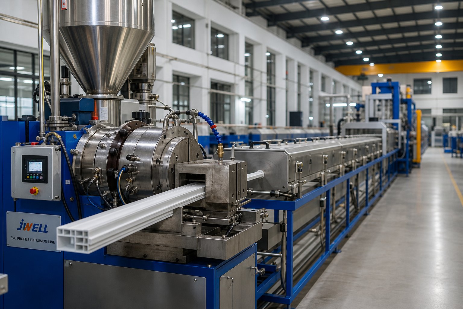
What Is PVC Profile Extrusion and Why It Matters
PVC profile extrusion is a continuous manufacturing process in which heated polyvinyl chloride compound is forced through a shaped die to produce uniform cross-section profiles of virtually unlimited length.
Imagine a single production line running around the clock, turning raw plastic powder into perfectly shaped window frames, cable conduits, or automotive seals — all without stopping. That is the power behind this process, and it is the reason extruded PVC shows up in nearly every built environment you walk through. Unlike batch processes such as injection molding, where each part is formed in a discrete cycle, profile extrusion operates continuously. Material enters one end, and a finished, constant-cross-section product emerges from the other, ready to be cut to any required length.
The fundamental principle is straightforward: a thermoplastic PVC compound — pre-blended with stabilizers, lubricants, pigments, and other additives — is fed into a heated extruder barrel. Rotating screws melt and homogenize the compound, then push it through a precision die whose opening mirrors the desired profile shape. After exiting the die, the still-soft extrudate is cooled, calibrated to exact dimensions, and cut. The result is a continuous PVC profile that can be as simple as a flat trim strip or as complex as a multi-chamber window frame.
Defining PVC Profile Extrusion
Two broad categories define the field. Rigid profile extrusion — often called uPVC or PVC-U extrusion — uses unplasticized compound to produce stiff, load-bearing shapes like window systems, siding trim, and electrical trunking. Flexible PVC extrusion, on the other hand, incorporates plasticizers into the compound, yielding soft, pliable profiles suited for edge seals, gaskets, and protective cable sleeving.
Common profile geometries fall into three groups:
- Solid profiles — flat strips, angle trims, and decorative moldings with a uniform, filled cross-section.
- Hollow profiles — tubes, channels, and single-cavity sections formed around a mandrel within the die.
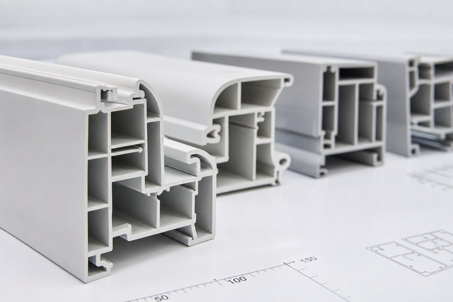
- Multi-chamber profiles — complex PVC profiles with internal webs and ribs, typical of high-performance window and door systems designed for thermal insulation and structural strength.
Why PVC Dominates Profile Applications
Why does PVC consistently win over aluminum, wood, or engineering plastics for profile applications? The answer comes down to a compelling mix of inherent material properties. PVC delivers excellent chemical resistance, inherent flame retardancy without expensive additives, and strong UV stability when formulated with appropriate stabilizer packages. It is also one of the most recyclable thermoplastics in commercial use, and its cost-to-performance ratio remains difficult to beat — especially for long production runs of extruded PVC parts where tooling cost is amortized over large volumes.
These advantages explain why PVC profiles are deeply embedded across major industries:
- Construction — Window frames, siding trim, rainwater guttering, and interior wall panels that resist moisture, rot, and insect damage.
- Electrical — Cable trunking, conduit systems, and wiring channels that leverage PVC's flame-retardant and insulating properties.
- Automotive — Edge trims, seals, and protective strips where lightweight durability and weather resistance are essential.
- Medical and consumer goods — Tubing, display channels, and point-of-sale fixtures that benefit from PVC's ease of customization and sterilizability.
- Agriculture and infrastructure — Irrigation system components, greenhouse framing, and cable management profiles exposed to harsh outdoor conditions.
Each of these sectors relies on a PVC profile that meets tight dimensional tolerances and consistent mechanical properties — outcomes that depend entirely on how well the extrusion process itself is controlled. And that control starts at the very first stage of the production line.
The PVC Profile Extrusion Process Stage by Stage
Every finished profile — whether a simple cable channel or a five-chamber window section — passes through the same core sequence of operations. Understanding each stage of the PVC extrusion process is essential because a deviation at any point ripples downstream, showing up as a surface blemish, a dimensional miss, or a brittle end product that fails in the field. Here is the complete plastic profile extrusion process broken into its primary stages:
- Raw material preparation and feeding
- Melting, plasticization, and metering
- Die shaping, calibration, cooling, haul-off, and cutting
Each stage has its own engineering purpose, key process variables, and failure modes. Let's walk through them.
Raw Material Preparation and Feeding
The extrusion profile PVC process begins long before compound enters the barrel. PVC resin — typically a fine, low-bulk-density powder — must be blended with thermal stabilizers, internal and external lubricants, impact modifiers, fillers such as calcium carbonate, and pigments. This blending happens inside a high-speed mixer, where rapidly rotating blades generate intense turbulence and frictional heat. As particles collide, additives adhere uniformly to each resin grain, and the batch temperature climbs to a target range (commonly around 110 °C to 130 °C for rigid PVC dry blends) before being discharged into a cooling mixer.
Why does this matter so much? If the dry blend is poorly homogenized, you'll see inconsistent stabilizer distribution — leading to localized degradation and discoloration in the finished profile. If residual moisture isn't driven off during mixing, trapped water vapor will create voids and bubbles after melting. And if the dosing system — whether gravimetric or volumetric — feeds material unevenly, the extruder sees fluctuating loads that translate into melt-pressure swings and wall-thickness variation.
Think of material preparation as setting the foundation. A flawed dry blend can't be corrected by downstream equipment; the defect is locked in before the screw ever touches the powder.
Melting, Plasticization, and Metering
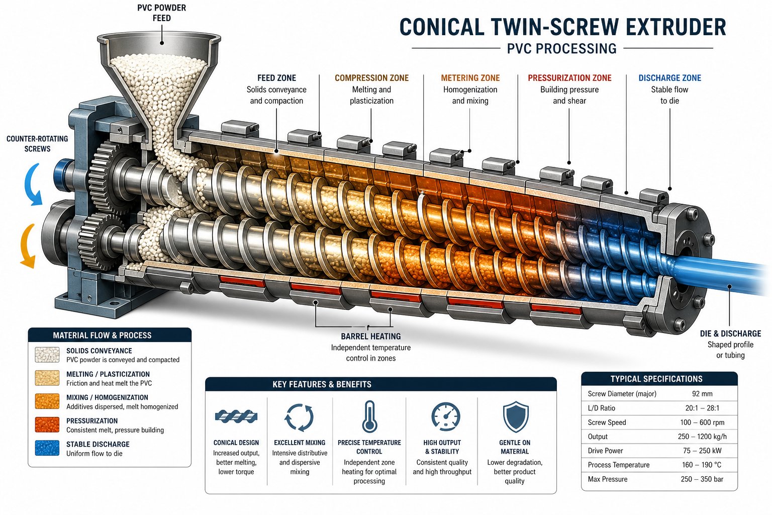
Inside the extruder — typically a conical twin-screw unit for rigid PVC extrusions — dry blend transforms into a homogeneous, fully gelled melt. Two counter-rotating, intermeshing screws pull powder from the feed throat and advance it through progressively tighter flight channels. Along the way, the compound experiences controlled shear, external barrel heating, and compression that together fuse individual PVC grains into a continuous melt.
PVC is uniquely shear-sensitive compared to polyolefins. Excessive mechanical energy input will push the melt beyond its narrow safe processing window, triggering thermal degradation and hydrochloric acid (HCl) release. Screw geometry must therefore balance two competing needs: enough distributive and dispersive mixing to ensure every grain is fully plasticized, yet low enough shear peaks to avoid localized overheating. The tapered design of a conical twin screw is particularly well-suited to this balance — a large feed diameter provides high intake volume for bulky powder, while the narrowing barrel generates progressive compression without abrupt shear spikes.
At the screw tips, the metering zone takes over. Its job is to deliver a steady, pulse-free stream of melt at consistent pressure to the die. Pressure fluctuations here — caused by worn screw flights, uneven feeding, or temperature imbalance — directly produce wall-thickness variation in the final profile. Monitoring melt pressure at the die adapter is one of the most reliable indicators of upstream process health.
Die Shaping, Calibration, and Cooling
As the homogeneous melt exits the extruder, it enters the profile die — a precision-machined tool whose internal flow channels distribute material evenly across the desired cross-sectional shape. Die design is critical: uneven flow velocities across the die lip result in warped or asymmetric profiles, while excessive shear at the land area can trigger surface defects like melt fracture.
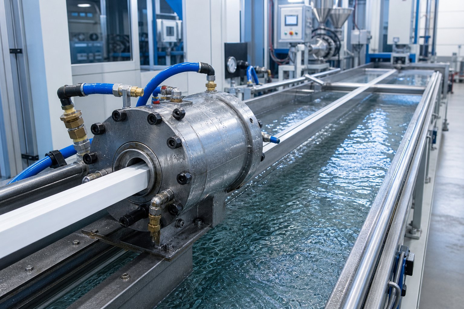
The extrudate leaving the die is still soft and dimensionally unstable. It immediately enters a vacuum calibration sleeve — a cooled, precision-machined tool connected to negative pressure. The vacuum draws the hot profile outward against the sleeve's inner walls, locking in the cross-sectional dimensions as cooling water removes heat. A PVC profile extrusion line typically follows this calibrator with one or more spray-cooling or immersion-cooling tanks. Tank length depends on line speed and profile wall thickness; insufficient cooling leaves residual heat trapped inside, which causes post-extrusion warpage and internal stress.
Downstream of the cooling tanks, a haul-off unit — usually a caterpillar-type puller with rubber-padded tracks — grips the solidified profile and draws it through the line at a constant speed. Sounds simple, but the haul-off speed must be precisely synchronized with extruder output. Pull too fast and the profile stretches, reducing wall thickness and introducing orientation stresses. Pull too slow and material backs up, causing compression marks or dimensional swelling.
Finally, a cutting station parts the continuous profile into specified lengths. Simple geometries use flying-saw cutters that travel with the profile during each cut to avoid stopping the line. Complex multi-chamber sections often require planetary cutters — rotating blade assemblies that orbit around the profile for chip-free, burr-free cuts essential to clean end joints.
Together, these stages form a tightly coupled system. A change in screw speed affects melt pressure, which affects die swell, which requires a haul-off adjustment, which shifts cooling demands. Recognizing these interdependencies is the first step toward dialing in parameters that deliver repeatable, defect-free PVC extrusions — and that is exactly where attention turns next.
Critical Processing Parameters for Rigid and Flexible PVC Profiles
Every stage described above depends on a handful of tightly interlocked variables. Change one, and the rest shift with it. The challenge with any plastic PVC extrusion profile is that PVC offers a remarkably narrow window between "not fully plasticized" and "actively degrading" — a window far tighter than what polyethylene or polypropylene processors are accustomed to. Dialing in parameters correctly is less about hitting a single magic number and more about maintaining a balanced relationship among temperature, screw speed, melt pressure, and line speed simultaneously.
Temperature Profiles and Thermal Management
Imagine the extruder barrel as a series of individually heated and cooled zones stretching from the feed throat to the die exit. Each zone serves a distinct purpose, and the temperature set points follow a deliberate logic rather than a flat, uniform value.
In the feed zone, temperatures are kept relatively low. The goal here is controlled material intake — not premature melting that would cause powder to stick and bridge above the screw flights. Moving into the compression and transition zones, barrel temperatures rise gradually. This controlled ramp, combined with increasing mechanical shear from the narrowing screw geometry, drives the fusion of individual PVC grains into a cohesive melt. By the metering zone, temperatures typically level off or decrease slightly to stabilize melt viscosity and prevent overheating just before the compound enters the die.
The die itself requires its own careful thermal management. Proper die temperature promotes smooth surface finish and stable melt flow. Set it too high, and you risk die drool and thermal degradation at the lip. Set it too low, and the increased melt viscosity creates rough surfaces and drives up back pressure — a point reinforced by PVC processing research linking low die temperatures directly to surface roughness and excessive torque.
Why is this so critical for PVC specifically? Unlike polyolefins that tolerate broad thermal swings, PVC begins releasing hydrochloric acid (HCl) and discoloring once its safe melt temperature ceiling is exceeded — even briefly. As Plastics Technology notes, rigid PVC has a very narrow processing range because of its rapid degradation if the processing temperature is exceeded. That narrow band makes zone-by-zone precision a non-negotiable requirement for every pvc plastic extrusion operation, whether you're running rigid window sections or flexible PVC extrusion for soft seals and gaskets. Flexible compounds, with their plasticizer content, tend to process at lower temperatures and tolerate slightly broader windows — but the degradation risk never disappears entirely.
Screw Speed, Melt Pressure, and Line Speed Relationships
Screw RPM is the primary lever controlling both shear energy input and volumetric output. Increase screw speed, and you push more material through the barrel per minute — but you also generate more frictional heat inside the melt. For rigid PVC, maximum peripheral screw speeds are often kept quite low compared to polyolefin processing, precisely because the material's viscosity at low shear rates can be extraordinarily high. Extrusion expert Jim Frankland highlights that RPVC viscosity at near-zero shear can reach roughly eight times that of comparable polyethylene grades, demanding substantial torque reserves — especially during startup.
Melt pressure at the die face is your real-time quality indicator. Consistent pressure means consistent wall thickness across the plastic extrusion profile; fluctuations signal trouble upstream — a feeding irregularity, worn screw flights, or a temperature imbalance disrupting the melt's uniformity. Monitoring this value continuously lets operators catch problems before they become scrap.
Haul-off speed, meanwhile, must stay in lockstep with extruder output. Pull the profile faster than the die delivers material, and you'll stretch the cross-section — thinning walls and embedding orientation stresses. Slow the haul-off below the extrusion rate, and material accumulates at the die exit, causing swelling and compression marks. The balance point is where the profile exits with its designed dimensions intact, under minimal tensile or compressive load.
The table below organizes these key parameters, their functions, and the consequences of deviation in either direction:
| Parameter | Function | Effect if Too High | Effect if Too Low |
|---|---|---|---|
| Barrel Temperature (Feed Zone) | Controls material intake and initial softening without premature melting | Powder sticks and bridges in the feed throat; inconsistent screw filling | Inadequate softening; high torque demand and poor initial fusion |
| Barrel Temperature (Compression/Metering Zones) | Drives grain fusion and melt homogeneity through conducted heat | Thermal degradation, HCl release, discoloration, and burn marks | Incomplete plasticization; rough surface, poor mechanical properties |
| Die Temperature | Ensures smooth melt flow and surface finish at the profile exit | Die drool, degradation at die lips, and dimensional instability | High back pressure, rough surface texture, increased extruder torque |
| Screw Speed (RPM) | Regulates shear energy input and volumetric output rate | Excessive shear heating; degradation risk and melt temperature overshoot | Insufficient output; poor fusion and low throughput efficiency |
| Melt Pressure (at Die) | Indicates melt uniformity and consistent die filling | Excessive die swell; potential equipment stress and flash at die lips | Incomplete die filling; thin walls, voids, and inconsistent profile geometry |
| Haul-Off (Line) Speed | Pulls the solidifying profile through calibration and cooling at a constant rate | Profile stretching; reduced wall thickness and orientation stress | Material buildup at die exit; swelling, compression marks, and dimensional excess |
Notice how each row connects to the others. Raising screw speed without adjusting barrel cooling shifts the melt temperature upward, which changes melt viscosity, which alters die pressure, which demands a haul-off correction — a cascade that underscores why experienced operators treat these parameters as a system rather than isolated dials. Resin manufacturer datasheets and recognized PVC processing guides remain the best sources for populating exact temperature values and RPM limits for a specific compound grade; the principles above provide the framework for interpreting and applying that data effectively.
With parameters balanced, the extruder delivers a stable, well-formed melt to the die. What happens after the melt exits — through calibration, cooling, pulling, and cutting — determines whether that stability translates into a finished product that actually meets spec. The downstream equipment chain carries just as much influence over final quality as the extruder itself.
Downstream Equipment from Calibration to Cutting
Most discussions of PVC profile extrusion end the moment melt leaves the die. That is a significant blind spot. The extruder can deliver a flawless, perfectly homogenized melt — and the finished product can still fail dimensional checks, warp on the shelf, or crack during installation if downstream equipment is poorly configured. Every unit between the die exit and the finished-goods pallet has a specific job, and each one directly shapes the quality of the pvc extrusion profiles your customer actually receives.
Here is the full downstream chain, broken into its two primary functional groups: sizing and cooling, then pulling, cutting, and packaging.
Vacuum Calibration and Cooling Systems
The hot, soft extrudate emerging from the die has roughly the right shape — but it lacks dimensional precision. That precision comes from the vacuum calibration sleeve, a water-cooled, precision-machined tool mounted immediately downstream of the die on a calibration table. A vacuum pump draws negative pressure inside the sleeve, which pulls the still-pliable profile outward against the sleeve's inner walls. This locks the cross-sectional geometry — wall thickness, chamber dimensions, outer contour — into place as heat is simultaneously extracted through contact with the cooled tooling surface.
Think of it this way: the die gives the profile its approximate shape, but the calibrator gives it its final dimensions.
After the calibrator, the profile passes through one or more cooling tanks. Two configurations dominate. Water-bath immersion tanks submerge the profile completely, providing aggressive, uniform cooling suited to heavy-wall or multi-chamber extruded plastic shapes. Spray-cooling tanks direct targeted water jets onto the profile surface, offering gentler heat removal that reduces the risk of thermal shock on thin-wall or asymmetric sections. In practice, many PVC profile extrusion lines combine both — an immersion bath for rapid initial cooling followed by spray tanks for gradual final solidification.
Tank length is not arbitrary. It must match line speed and profile wall thickness. A thicker profile at higher line speed needs more cooling length; shortchange it, and residual heat trapped in the core will release after cutting, causing post-extrusion warpage and built-in residual stress that degrades long-term mechanical performance. Getting this calculation right is the difference between plastic extrusion profiles that stay straight on a job site and ones that bow in storage.
Haul-Off, Cutting, and Packaging Systems
Downstream of the cooling tanks, a haul-off unit takes over the critical task of pulling the solidified profile through the entire line at a constant, slip-free speed. Two main types compete here:
Caterpillar (track-type) haul-offs use opposing rubber-padded tracks that grip the profile along a generous contact length. Their high pulling force and speed versatility make them the standard choice for heavy, rigid profiles like window systems and large trunking. Belt-type haul-offs, by contrast, use flat belts for a gentler touch — ideal for smaller, thinner, or surface-sensitive extruded profiles plastic manufacturers need to keep mark-free. Regardless of type, the core requirement is identical: constant pull speed with minimal slip. Even small speed fluctuations translate directly into wall-thickness variation and length inconsistency in the finished product.
Cutting is where the continuous process becomes discrete parts. The right cutter depends on profile geometry and material rigidity:
Flying-saw cutters — essentially circular saws mounted on a traveling table that moves with the profile during each cut — handle simple, rigid profiles efficiently. The saw clamps to the moving extrudate, makes its cut, then retracts to reset. As Conair's extrusion specialists note, these traveling-saw setups are often paired with servo-controlled tables for tighter length tolerances and repeatable square cuts.
Planetary cutters take a different approach entirely. A circular cutting wheel orbits around the profile on a rotating ring, gradually splitting the material apart without removing any chips or generating particulate. The result is an exceptionally clean, distortion-free cut — critical for complex multi-chamber window profiles and any application feeding into automated assembly. Planetary cutters typically cost more and operate at lower line speeds, but they often eliminate secondary finishing operations entirely, which offsets the speed trade-off.
After cutting, the finished lengths move through final handling: protective film application to preserve surface quality during shipping, automated stacking onto collection tables, and bundling or palletizing for dispatch.
Here is the complete downstream equipment sequence, from calibrator to shipping-ready product:
- Vacuum calibration sleeve — Applies negative pressure to lock the profile's cross-sectional dimensions against precision-machined tooling.
- Calibration table — Supports and aligns the calibrator and initial cooling tank; allows fine positional adjustment relative to the die.
- Immersion cooling tank(s) — Submerges the profile in temperature-controlled water for rapid, uniform heat extraction.
- Spray cooling tank(s) — Directs targeted water jets for gentler final-stage cooling, reducing thermal shock and residual stress.
- Haul-off unit — Grips the cooled profile and pulls it through the line at constant speed, using caterpillar tracks or flat belts.
- Flying-saw or planetary cutter — Parts the continuous profile into specified lengths with square, burr-free ends.
- Protective film applicator — Laminates a peel-off film onto visible surfaces to prevent scratches during handling and transport.
- Stacking table / collection conveyor — Accumulates cut lengths and orients them for bundling.
- Bundling and palletizing station — Straps, wraps, or boxes finished profiles for shipment to the end customer.
Each unit in this chain is only as effective as its synchronization with everything upstream. A perfectly calibrated profile will still fail if the haul-off slips, and a flawless cut means nothing if the cooling tanks left residual stress that warps the piece overnight. Recognizing how all of these elements interact — and how they compare to alternative manufacturing methods — is what separates a competent extrusion operation from a truly optimized one.
PVC Profile Extrusion vs Alternative Manufacturing Methods
Choosing the right manufacturing process is just as consequential as choosing the right material. You might have the perfect PVC compound formulated, your die designed, and your downstream line spec'd — but if continuous extrusion isn't the best fit for the part geometry, volume, or performance requirements in front of you, all that preparation goes to waste. So how does plastic profile extrusion stack up against the alternatives, and when should you pick one over the other?
Three processes most frequently compete for the same applications: injection molding, pultrusion, and co-extrusion. Each serves a distinct purpose, and understanding where they overlap — and where they don't — helps engineers and procurement teams avoid costly mismatches between process and product.
Extrusion vs Injection Molding for PVC Parts
The fundamental distinction comes down to geometry. Extrusion produces continuous lengths with a constant cross-section — think window frames, cable channels, or edge trims that can run meters long without any change in shape. Injection molding, by contrast, fills a closed mold cavity to create discrete, three-dimensional parts with features like bosses, ribs, snap fits, and internal cavities that would be impossible to achieve in a continuous process.
Tooling cost is another major differentiator. An extrusion die is a comparatively simple steel block with a shaped opening; it costs a fraction of a hardened-steel injection mold engineered for tight tolerances and long service life. As Fictiv's manufacturing comparison notes, extrusion dies are simpler, easier to machine, and therefore less expensive to produce — giving extrusion a faster return on investment for high-volume, constant-cross-section parts.
Per-unit economics shift with volume and complexity. For long, uniform plastic profiles produced at high throughput, extrusion wins convincingly because the continuous process eliminates cycle-by-cycle mold filling, cooling, and ejection steps. Material waste is also minimal — there are no runners, sprues, or gates to regrind. Injection molding, however, becomes the clear choice when you need complex 3D plastic extrusion shapes with variable wall thicknesses, textured surfaces, or integrated functional features that a uniform cross-section simply cannot deliver.
Here is a practical rule of thumb: if you can describe the part by drawing a single cross-section and extending it to length, extrusion is almost certainly the more efficient path. The moment the geometry demands features that change along the part's length, injection molding takes over.
Extrusion vs Pultrusion and Co-Extrusion
Pultrusion sounds similar to extrusion, and the two processes do share a common principle — material passes continuously through a shaped die to produce a constant cross-section. The critical difference lies in the material and the driving mechanism. In pultrusion, continuous reinforcing fibers — typically glass, carbon, or aramid — are saturated with a thermoset resin (polyester, vinyl ester, or epoxy) and pulled through a heated die where the resin cures into a rigid composite. As Tencom's cross-sectional analysis explains, extrusion pushes thermoplastic material through a die, whereas pultrusion pulls fiber-reinforced thermoset material through one.
The resulting pultruded profiles are exceptionally strong for their weight — fiberglass-polyester composites can deliver roughly three times the tensile strength of extruded 6063 aluminum at a fraction of the density. That makes pultrusion ideal for structural applications demanding high strength-to-weight ratios: bridge decking, utility crossarms, antenna radomes, and tool handles. PVC profile extrusion, on the other hand, excels where chemical resistance, flame retardancy, recyclability, and cost efficiency matter more than ultimate structural performance — which is exactly why it dominates building fenestration, electrical enclosures, and interior trim.
Co-extrusion deserves its own distinction because it isn't a competing process — it's an enhancement of standard extrusion. Multiple extruders feed different materials into a single die simultaneously, producing a profile with distinct layers bonded together in a single pass. The most common example in the window industry is a rigid PVC core co-extruded with a thin cap layer of Acrylonitrile Styrene Acrylate (ASA) — a weatherable thermoplastic whose saturated rubber phase resists UV degradation far better than standard PVC alone. This capstock strategy delivers premium surface aesthetics and long-term color retention at near-commodity pricing, because the expensive ASA layer can be as thin as 0.5 mm while the cost-effective PVC core provides all the structural performance.
Co-extrusion also enables combinations like rigid-core profiles with flexible soft-lip seals, eliminating a secondary assembly step. The trade-off is added equipment complexity — each material stream requires its own extruder, and the die must be engineered to merge distinct melt flows without delamination.
The comparison table below organizes all four processes across the criteria that matter most when selecting a manufacturing method for extruded plastic profiles or their alternatives:
| Process | Typical Materials | Part Geometry | Tooling Cost | Volume Suitability | Primary Applications |
|---|---|---|---|---|---|
| PVC Profile Extrusion | Rigid (uPVC) and flexible PVC compounds | Continuous, constant cross-section — solid, hollow, or multi-chamber | Low to moderate (single die) | Medium to very high volume; continuous operation | Window frames, cable trunking, siding trim, edge seals, conduit |
| Injection Molding | Wide range of thermoplastics and elastomers (PVC, ABS, PC, nylon, LSR) | Complex 3D shapes with variable wall thickness, ribs, bosses, and internal cavities | Moderate to high (hardened steel molds for tight tolerances) | High volume for ROI; soft tooling for prototyping | Housings, connectors, caps, fittings, automotive interior components |
| Pultrusion | Thermoset resins (polyester, vinyl ester, epoxy) reinforced with glass, carbon, or aramid fibers | Continuous, constant cross-section — typically solid or simple hollow | Low to moderate (heated steel die) | Medium to high volume; continuous operation | Structural beams, bridge decking, utility poles, ladder rails, tool handles |
| Co-Extrusion | Multiple thermoplastics in layered combination (e.g., PVC core + ASA cap layer) | Continuous, constant cross-section with distinct material layers | Moderate to high (multi-channel die + multiple extruders) | Medium to high volume; continuous operation | Window profiles with weatherable cap layers, rigid/soft-seal combinations, colored capstock siding |
Notice the pattern: every continuous process in the table excels at producing long parts with a uniform cross-section, while injection molding owns the space where three-dimensional complexity is required. The decision often comes down to a simple question — does the part's value come from its length and consistency, or from its geometric complexity? For the vast majority of plastic profiles used in construction, electrical, and automotive trim applications, the answer is length and consistency, which is precisely why PVC profile extrusion remains the dominant choice.
Selecting the right process, though, is only half the equation. Even within extrusion, the profile's cross-sectional design determines die complexity, production speed, and long-term tooling maintenance. A poorly designed cross-section can turn a straightforward extrusion job into a chronic source of scrap — which is why design-for-manufacturability principles deserve just as much attention as process selection itself.
Designing PVC Profiles for Manufacturability
A profile that looks perfect on a CAD screen can become a nightmare at the die. Thick corners that refuse to cool evenly, asymmetric chambers that warp the moment they leave the calibrator, sharp internal angles where degraded material accumulates and chars — these are the kinds of problems that never appear in a 3D model but show up relentlessly on the production floor. Design-for-manufacturability (DFM) bridges that gap. It is the discipline of shaping a plastic profile so that the extrusion process can actually produce it — consistently, economically, and at the quality level your end customer demands.
Whether you are developing custom plastic profiles for a new window system or refining an existing cable channel, the geometry choices you make at the design stage lock in die complexity, production speed, scrap rate, and total cost. Getting those choices right upfront saves months of tooling iterations downstream.
Wall Thickness and Cross-Section Geometry Rules
If there is one golden rule in profile design, it is this: keep wall thickness as uniform as possible across the entire cross-section. Why? Because PVC cools from the outside in. When a thick section sits adjacent to a thin one, the thin wall solidifies and shrinks first while the thick section remains molten inside. That differential cooling creates internal stresses, sink marks on the surface, and warpage that no amount of calibration adjustment can fully correct.
For rigid PVC profiles, practical wall thicknesses typically range from roughly 1.0 mm up to about 3.0 mm for standard extrusion tooling. Go thinner than the lower end and the melt struggles to fill the die land consistently, leading to weak spots and tearing. Go much thicker and cooling times extend dramatically — slowing line speed, increasing residual stress, and raising the risk of internal voids where the core remains molten long after the skin has solidified.
Multi-chamber window profiles illustrate how to add structural rigidity without resorting to massive wall thickness. Internal ribs and webs — thin partitions dividing the profile's interior into separate chambers — dramatically increase the section's moment of inertia while adding minimal material. As Okotech's analysis of uPVC profiles highlights, these multiple chambers improve thermal insulation, acoustic dampening, and resistance to extreme weather loads, all without the weight penalty of solid construction. The key design constraint is that rib thickness should stay close to the outer wall thickness — typically at or slightly below it — to avoid differential cooling problems at the junctions.
Corner radii matter just as much as wall thickness. Sharp internal corners create dead zones in the die where melt velocity drops and material residence time increases. The result is localized degradation, die-lip buildup (plate-out), and visible surface blemishes on the finished product. Generous internal radii — a minimum of 0.5 mm, with larger radii preferred — promote smooth, laminar melt flow through the die land and extend die service life by reducing the cleanup frequency.
Hollow Sections, Snap Fits, and Functional Features
Hollow profiles introduce an extra layer of tooling complexity: mandrel support. The die must contain an internal mandrel — a cantilevered or spider-supported tool element — that forms the hollow interior of the profile while the outer die plate shapes the external contour. Material flows around the mandrel supports and must rejoin seamlessly on the downstream side. If the mandrel is poorly positioned or the flow channels are unbalanced, visible weld lines or weak knit lines appear in the finished part. Symmetry in the cross-section helps enormously here, because balanced flow paths naturally equalize pressure around the mandrel and minimize knit-line severity.
Many modern profiles integrate functional features directly into the extruded cross-section — gasket grooves, screw channels for hardware attachment, snap-fit legs that clip into mating components, and co-extruded soft-lip seals for weathertight joints. Each added feature increases die complexity and cost. A screw channel with tight dimensional tolerance, for example, requires precise die land geometry and careful calibration to hold its shape through cooling. Snap-fit features with thin cantilevered legs may require custom pvc extrusion tooling with delicate die inserts that wear faster and demand more frequent replacement.
The practical takeaway? Every feature you add to a plastic profile cross-section should earn its place. If a gasket groove can be simplified without sacrificing seal performance, or a snap-fit leg can be thickened slightly to ease die filling, those adjustments pay dividends in lower tooling cost, longer die life, and fewer rejected parts. Custom vinyl extrusion projects with highly complex cross-sections often benefit from early collaboration between the product designer and the die maker — catching potential flow and cooling issues before steel is ever cut.
The following checklist consolidates the core DFM best practices every profile designer should verify before releasing a cross-section for tooling:
- Wall uniformity — Keep wall thickness variations within 15-20% across the cross-section to minimize differential cooling and warpage.
- Corner radii — Specify generous internal radii (minimum 0.5 mm) to promote smooth melt flow and prevent die-lip buildup.
- Profile symmetry — Design symmetric cross-sections wherever possible to balance material flow, reduce knit-line severity, and simplify calibration.
- Draw ratio — Keep the ratio between the die opening area and the final profile area within limits recommended by the die designer to avoid excessive die swell or stretching.
- Rib and web thickness — Size internal ribs at or slightly below outer wall thickness to prevent sink marks at rib-wall junctions.
- Hollow section mandrel access — Ensure hollow cavities are large enough for mandrel tooling and that the die can be disassembled for cleaning without excessive downtime.
- Feature consolidation — Minimize the number of intricate features (thin snap legs, deep grooves, sharp notches) to reduce die cost and extend service life.
- Surface finish expectations — Specify surface quality requirements early; high-gloss finishes demand polished die lands and tighter thermal control, adding cost.
- Co-extrusion zones — If soft-lip seals or capstock layers are co-extruded, define material boundaries clearly and ensure adequate adhesion between substrate and cap layer.
A well-designed cross-section does more than simplify die fabrication. It reduces scrap during startup, shortens the time needed to dial in parameters, and extends intervals between die maintenance shutdowns. In short, it makes every downstream stage — from calibration to cutting — easier to control. And control is exactly what you need when the next challenge is diagnosing and eliminating the defects that inevitably arise during production runs.
Common PVC Extrusion Defects and Troubleshooting
You've got your parameters dialed in, your downstream equipment synchronized, and your profile design optimized for manufacturability. Then a defect appears on the line — a rough patch on the surface, a slight bow in an otherwise straight section, or a profile that snaps instead of flexing during quality checks. What went wrong, and more importantly, how do you fix it without chasing symptoms blindly?
The key is classifying the problem first before touching any settings. PVC extrusion defects fall into two broad categories: surface defects visible to the eye, and dimensional or structural defects that may only reveal themselves during testing. Each has distinct root causes and corrective paths. Let's break them down.
Surface Defects and Their Root Causes
Shark skin (melt fracture) shows up as a fine, repetitive roughness — almost like orange peel — across the profile surface. It happens when shear stress at the die lip exceeds the melt's elastic limit, causing the surface to fracture as it exits. Reducing screw speed, raising die temperature slightly, or adjusting the external lubricant package to lower die-land friction are typical corrective actions.
Die lines are longitudinal streaks that run the entire length of extruded PVC profiles. They are almost always mechanical in origin — a scratch on the die land, a nick from cleaning, or hardened buildup on the die lip dragging through the soft melt. The fix is straightforward: disassemble, inspect, and polish the die surfaces. Preventing buildup through proper lubrication balance is equally important.
Surface roughness without the repetitive pattern of shark skin typically signals incomplete plasticization. The melt is too cold or hasn't had enough residence time to fully fuse. As industry troubleshooting guides confirm, raising barrel temperatures in the early compression zones and verifying that plasticization reaches the optimal level usually restores a glossy finish.
Discoloration and burn marks point to thermal degradation. PVC's narrow processing window means even a few degrees above the safe ceiling — or a dead zone inside the die where material stagnates — can trigger HCl release, turning white compound yellow or brown. Stabilizer-focused diagnostics recommend checking heat history first: melt temperature, residence time, and start/stop behavior. Lowering barrel temperatures, shortening residence time, and ensuring no hot spots exist in the adaptor or die entry are the primary fixes.
Plate-out — a waxy or crusty deposit that accumulates on die lips and calibrator surfaces — is subtler. It stems from lubricant or stabilizer components migrating to metal surfaces and solidifying. The result is streaks and drag marks on the extruded plastic profile surface. Rebalancing the internal-to-external lubricant ratio and optimizing the wax package are the recommended first steps, followed by tracking cleaning intervals to verify improvement.
Dimensional and Structural Defects
Warpage is one of the most frustrating defects in plastic profile extrusions because it often appears hours after cutting — on the stacking table or even at the customer's facility. Uneven cooling is the most common culprit: if one side of the profile receives more water contact than the other, differential shrinkage pulls it into a curve. Asymmetric cross-section design compounds the problem. Alignment checks — verifying that the extruder, die, calibrator, and cooling tank share a straight centerline — are the essential first diagnostic step, followed by balancing spray nozzle coverage and ensuring cooling tanks provide sufficient length for full solidification.
Dimensional instability — wall thickness drift, outer-dimension fluctuation, or meter-weight variation from piece to piece — usually traces back upstream. Inconsistent haul-off speed, melt pressure fluctuations from worn screw flights, or feeding irregularities all manifest as parts that measure differently from one cut to the next. Continuous melt-pressure monitoring at the die adapter is the fastest way to distinguish extruder-side problems from downstream speed mismatches.
Internal voids appear as bubbles or hollow pockets within the profile wall. Two sources dominate: moisture in the dry blend that flashes to steam inside the barrel, and decompression zones in the metering section where the melt pulls apart momentarily. Drying raw materials thoroughly and checking the extruder's vacuum venting system are the direct corrective actions.
Brittleness turns pvc extruded profiles into a liability — parts crack during installation or fail impact testing. Excessive filler loading (particularly calcium carbonate beyond the compound's tolerance) and insufficient plasticization are the usual suspects. As experienced processors note, reducing filler content, increasing impact modifier dosage, and ensuring barrel temperatures allow full molecular fusion are the proven remedies.
The table below consolidates these defects into a quick-reference format for production floor use:
| Defect Name | Visual Symptom | Root Cause(s) | Corrective Action(s) |
|---|---|---|---|
| Shark Skin (Melt Fracture) | Fine, repetitive surface roughness resembling orange peel | Excessive shear stress at the die lip; melt elasticity exceeded | Reduce screw speed; raise die temperature; adjust external lubricant to lower die-land friction |
| Die Lines | Continuous longitudinal streaks along the profile length | Scratches, nicks, or hardened buildup on die land surfaces | Disassemble and polish die surfaces; remove buildup; rebalance lubrication to prevent recurrence |
| Discoloration / Burn Marks | Yellow, brown, or black streaks or patches on the surface | Thermal degradation from excessive barrel temperature, long residence time, or dead zones in die/adaptor | Lower barrel temperatures; reduce residence time; eliminate hot spots; strengthen stabilizer synergy |
| Plate-Out | Waxy or crusty deposits on die lips causing surface streaks | Lubricant or stabilizer migration to metal surfaces; internal/external lube imbalance | Rebalance lube ratio; optimize wax package; consider lower-plate-out stabilizer system; track cleaning intervals |
| Warpage | Profile curves, bows, or twists after cutting | Uneven cooling; asymmetric cross-section design; equipment misalignment | Balance spray coverage on all sides; verify centerline alignment of all equipment; ensure adequate cooling tank length |
| Dimensional Instability | Wall thickness drift; outer dimensions vary between cuts | Melt pressure fluctuations; inconsistent haul-off speed; feeding irregularities; worn screw flights | Monitor melt pressure continuously; synchronize haul-off with extruder output; inspect screws for wear; stabilize feeding |
| Internal Voids / Bubbles | Hollow pockets or surface bubbles within the profile wall | Moisture in raw material flashing to steam; decompression in the metering zone; inadequate venting | Dry raw materials thoroughly; check and clean vacuum venting system; verify hopper dryer function |
| Brittleness | Profile cracks or shatters during cutting, impact testing, or installation | Excessive filler loading; insufficient plasticization; inadequate impact modifier in formulation | Reduce filler content; increase CPE or ACR impact modifier; raise barrel temperatures to improve fusion |
Notice a pattern across these corrective actions? Many defects trace back to the same upstream variables — melt temperature, plasticization quality, and the consistency of material delivery from the screw and barrel system. A worn barrel that can no longer maintain tight compression, or screw flights that have lost their geometry to abrasive fillers, will generate multiple defect types simultaneously: rough surfaces from poor plasticization, dimensional drift from inconsistent melt pressure, and discoloration from uneven shear heating. That connection between plastic extruded profiles quality and the core plasticizing hardware is exactly why screw and barrel selection deserves its own focused discussion.
How Screw and Barrel Technology Drives Profile Quality
Multiple defect types — rough surfaces, dimensional drift, discoloration — often share a single origin: the screw and barrel system that plasticizes the compound. Swap out any other downstream component and you can usually compensate. Let the core plasticizing hardware deteriorate, and every profile off the line suffers. That makes screw and barrel selection one of the highest-impact equipment decisions for any PVC profile extruder on the market.
Why Conical Twin Screw Barrels Excel for PVC Processing
Rigid PVC dry blends are low-bulk-density powders with a narrow safe processing window. A conical twin-screw design addresses both challenges simultaneously. The large-diameter feed end provides generous intake volume, pulling in bulky powder without bridging or starving. As the screws taper toward the discharge, material is compressed progressively — not abruptly — which limits the shear peaks that cause localized overheating and HCl release in heat-sensitive PVC.
Counter-rotating, intermeshing screws add two more advantages. First, they create positive conveying — material is pushed forward in enclosed C-shaped chambers rather than relying on drag flow alone. This produces a narrow residence time distribution, meaning every particle spends roughly the same amount of time in the barrel and receives roughly the same thermal-mechanical history. Second, the self-wiping action of intermeshing flights prevents stagnant pockets where degraded material could accumulate, char, and eventually contaminate the melt stream.
How do alternatives compare? Single-screw extruders rely on frictional drag to move material forward, which limits their ability to handle low-bulk-density powders and makes them more prone to inconsistent plasticization with rigid PVC. Parallel twin-screw extruders — typically co-rotating — excel at compounding and high-throughput mixing, but as Rollepaal's engineering comparison points out, conical machines historically offered mechanical advantages in the gearbox area and deliver gentler processing suited to PVC's thermal sensitivity. That said, parallel designs are gaining ground for larger outputs due to greater screw-design freedom and a potentially wider processing window. For most pvc window extruders and standard-output plastic profile extruder applications, though, the conical twin-screw configuration remains the workhorse — and for good reason.
Wear Resistance and Consistent Plasticizing Performance
Even the best screw geometry degrades over time, and PVC compounds accelerate that process. Calcium carbonate fillers, titanium dioxide pigments, and glass-fiber reinforcements in certain specialty blends are abrasive. Run after run, they erode screw flights and barrel bore surfaces. As clearances widen, compression efficiency drops — the barrel can no longer build the tight, consistent melt pressure the die demands. You'll notice it first as subtle wall-thickness variation, then as rising energy consumption (the motor works harder to compensate for lost efficiency), and eventually as surface defects from incomplete plasticization.
This is why metallurgy matters as much as geometry. Bimetallic barrel linings — hard protective coatings typically 1-2 mm thick applied to the bore's working surface — dramatically extend service life when processing abrasive PVC compounds. Nitrided screw surfaces and wear-resistant alloy compositions further protect flight edges and root diameters from erosion. The payoff is measurable: longer intervals between rebuilds, more stable output from shift to shift, and lower total cost of ownership for the pvc profile machine.
When evaluating conical twin screw barrels — whether for a new line or as replacement components — these are the performance criteria that separate adequate hardware from equipment that actually holds tolerances over thousands of production hours:
- Output stability — Consistent volumetric throughput without pressure surges, even across extended production campaigns.
- Plasticizing uniformity — Complete, homogeneous melt fusion with minimal temperature variation across the melt cross-section.
- Wear resistance — Bimetallic linings and hardened flight surfaces that maintain tight bore-to-flight clearances despite abrasive fillers.
- Energy efficiency — Optimized compression ratios and flight geometry that achieve full plasticization without excessive motor load.
- Compatibility with custom screw geometries — Barrel bore tolerances and surface finishes engineered to pair with application-specific screw designs for different PVC formulations.
For manufacturers sourcing custom or replacement conical twin screw barrels, NANHAIYA specializes in exactly this equipment category — engineering barrels specifically for PVC profile, pipe, sheet, and WPC extrusion with a focus on wear-resistant metallurgy and consistent plasticizing performance. Their product line is worth evaluating against the criteria above, particularly if your current barrels are showing signs of clearance-related output drift or rising energy draw.
Reliable plasticizing hardware keeps melt quality consistent — but consistent melt quality only matters if you can verify the finished profile actually meets the standards your market requires. That verification depends on a structured quality assurance framework backed by recognized industry standards and modern inspection methods.
Industry Standards and Quality Assurance for PVC Profiles
A profile can exit the line with a flawless surface, perfect dimensions, and full plasticization — and still be unsellable. Why? Because without documented compliance to the standards governing your target market, no specifier, building inspector, or OEM purchasing manager will accept it. Standards are not paperwork exercises. They are market-access requirements that dictate material composition, dimensional tolerances, impact performance, weathering resistance, and flammability behavior. Every pvc extrusion manufacturer competing for construction, electrical, or automotive contracts must build quality systems around these benchmarks from day one.
Key Standards Governing PVC Profiles
The landscape of standards is broad, but a handful of specifications carry outsized importance for plastic profiles manufacturers serving global markets. Each one targets a specific combination of material properties and end-use performance criteria:
- ASTM D1784 — Establishes the classification system and physical property requirements for rigid PVC and CPVC compounds. As the ASTM specification framework details, D1784 provides a uniform classification ensuring that materials meet specific quality, strength, and durability requirements across different applications — serving as the foundation for material selection and quality control in both pipe and profile production.
- ASTM D4216 — Covers rigid PVC and related copolymer building products, specifying compound classification for siding, soffit, accessories, and window components where weathering performance and dimensional stability are critical acceptance criteria.
- ISO 1163 — Provides the international designation system for PVC materials, enabling consistent identification of compound grades across borders so that pvc extrusion suppliers and buyers speak the same technical language regardless of geography.
- EN 12608 — The European harmonized standard for PVC-U profiles used in window and door fabrication. It defines requirements for material composition, dimensional tolerances, impact resistance at low temperatures, heat reversion, welding strength, and accelerated weathering performance — including maximum allowable color change (typically deltaE less than 5 after 2000 hours of xenon arc exposure). Meeting EN 12608 is mandatory for CE marking compliance in pvc window extrusion products entering the European construction market.
- UL ratings (UL 651, UL 1685) — Underwriters Laboratories standards governing electrical conduit and cable management profiles. These specify flame spread, smoke generation, and mechanical integrity requirements that profiles must pass before they can be installed in electrical raceways and plenum spaces.
What ties all of these standards together is their focus on measurable, repeatable performance. They specify not just what properties a profile must exhibit, but exactly how those properties are tested — removing ambiguity and ensuring that a profile qualifying in one laboratory will qualify in another. For pvc extrusion manufacturers targeting multiple regions, understanding which standards apply to each product line is a planning exercise that should happen before tooling is ordered, not after the first shipment is rejected.
Inline and Offline Quality Inspection Methods
Meeting standards requires more than a final-inspection mindset. Modern quality assurance blends continuous inline monitoring with periodic offline testing to catch deviations before they become scrap — or worse, field failures.
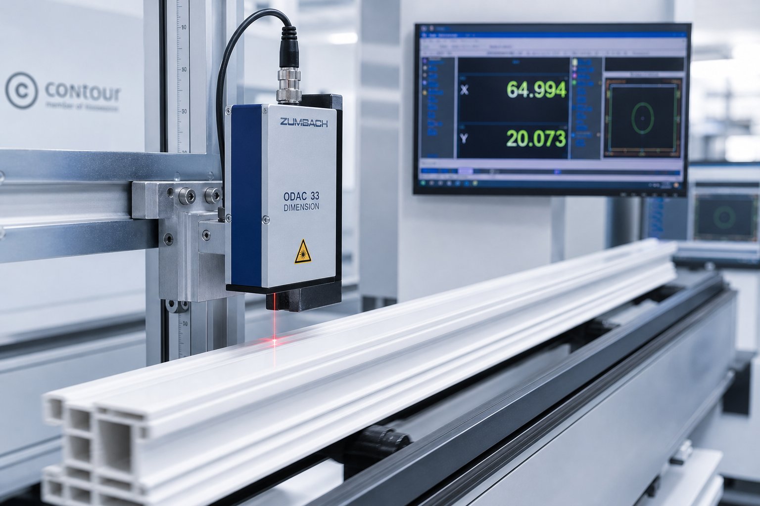
Inline dimensional measurement is the first line of defense. Laser micrometer systems and radar-based sensors measure wall thickness, outer diameter, and profile contour continuously as the product moves through the line. As demonstrated by radar-based measurement technology deployed on PVC extrusion lines, these systems achieve measurement accuracy of plus or minus 0.05 mm even at production line speeds, revealing process drift in real time so operators can correct before non-conforming product accumulates. When integrated with gravimetric feeders and haul-off speed controls, they enable closed-loop automation that maintains wall thickness within tight tolerance bands shift after shift — a capability that directly supports compliance with the dimensional requirements in EN 12608 and ASTM specifications.
Offline testing covers properties that cannot be assessed in-process:
- Impact testing — Charpy or Izod impact tests per ASTM D256 or ISO 179 quantify fracture resistance at controlled temperatures, verifying that the compound's impact modifier system performs as formulated.
- Color spectrophotometry — Spectrophotometers measure CIELAB color coordinates (L*, a*, b*) to track batch-to-batch color consistency. Industry specifications commonly require total color difference (deltaE) below 1.0 between production lots for visible architectural profiles.
- Accelerated weathering — Xenon arc or UV-fluorescent exposure chambers subject profile samples to intensified UV radiation, temperature cycling, and moisture per ASTM G155 and ISO 4892 protocols. These tests compress years of outdoor exposure into months, revealing stabilizer depletion, chalking, and embrittlement long before products reach the field.
- Heat reversion — Oven exposure at elevated temperatures measures dimensional change in the extrusion direction, detecting residual orientation stresses locked in during processing. High reversion values signal insufficient cooling or excessive haul-off tension — problems that would eventually manifest as warping in service.
Compliance with relevant industry standards is not optional for profiles entering construction, electrical, or automotive supply chains — it is a non-negotiable market-access requirement that determines whether your product can be specified, installed, and insured.
Here is a critical point that quality teams sometimes overlook: inspection systems can only verify what the process delivers. If upstream melt delivery is inconsistent — pressure surging, temperature drifting, plasticization varying from one screw revolution to the next — even the best inline sensors will simply document a stream of non-conforming measurements rather than preventing them. The consistency of the screw and barrel system is foundational to meeting the tight dimensional and mechanical tolerances these standards demand. Purpose-built components like NANHAIYA's conical twin screw barrels, engineered specifically for stable output and uniform plasticization in PVC processing, represent the kind of upstream investment that makes downstream compliance achievable rather than aspirational.
Standards and inspection methods give you the framework to prove quality. Reliable plasticizing hardware gives you the process stability to actually achieve it. Together, they close the loop between what your customers require and what your extrusion line consistently delivers — turning compliance from a reactive burden into a built-in competitive advantage.
Frequently Asked Questions About PVC Profile Extrusion
1. What is the difference between rigid and flexible PVC profile extrusion?
Rigid PVC profile extrusion (uPVC) uses unplasticized compound to produce stiff, structural shapes such as window frames, siding trim, and electrical trunking. Flexible PVC extrusion incorporates plasticizers into the compound, yielding soft, pliable profiles ideal for edge seals, gaskets, and cable sleeving. The two categories differ in processing temperature, melt behavior, and downstream cooling requirements. Rigid compounds demand tighter thermal control due to a narrower safe processing window, while flexible formulations tolerate slightly broader temperature ranges but still carry degradation risk if overheated.
2. Why are conical twin-screw extruders preferred for PVC profile production?
Conical twin-screw extruders are favored because their tapered barrel geometry matches PVC's unique processing demands. The large feed-end diameter efficiently intakes low-bulk-density PVC powder, while the progressive taper compresses material gradually — avoiding the abrupt shear spikes that trigger thermal degradation and HCl release. Counter-rotating intermeshing screws provide positive conveying with a narrow residence time distribution, ensuring uniform plasticization. The self-wiping flight action also prevents material stagnation and charring. Suppliers like NANHAIYA engineer conical twin screw barrels with wear-resistant bimetallic linings specifically for this application, helping maintain output stability over thousands of production hours.
3. What are the most common defects in PVC extrusion and how do you fix them?
The most frequent PVC extrusion defects include shark skin (melt fracture from excessive die-lip shear), die lines (caused by scratched or fouled die surfaces), discoloration (thermal degradation from overheating or stagnant melt zones), warpage (uneven cooling or equipment misalignment), and brittleness (insufficient plasticization or excessive filler loading). Effective troubleshooting starts by classifying whether the defect is surface-related or dimensional/structural, then tracing it to specific upstream variables such as barrel temperature, screw speed, melt pressure, or compound formulation. Many defects share a common origin in inconsistent melt delivery from worn screws and barrels.
4. How does PVC profile extrusion compare to injection molding?
PVC profile extrusion produces continuous lengths with a constant cross-section — window frames, cable channels, trim strips — at low tooling cost and minimal material waste. Injection molding creates discrete three-dimensional parts with complex features like bosses, ribs, and internal cavities that extrusion cannot achieve. Extrusion die tooling costs a fraction of a hardened injection mold, making it far more economical for high-volume, uniform-cross-section parts. The decision rule is straightforward: if the part can be described by a single cross-section extended to length, extrusion is typically the more efficient and cost-effective manufacturing path.
5. What industry standards must PVC profiles meet for construction and electrical applications?
PVC profiles for construction must typically comply with ASTM D1784 and ASTM D4216 for compound classification in the North American market, and EN 12608 for window and door profiles in Europe — covering dimensional tolerances, impact resistance, heat reversion, and accelerated weathering. Electrical conduit and cable management profiles require UL ratings such as UL 651 and UL 1685, which specify flame spread, smoke generation, and mechanical performance. Internationally, ISO 1163 provides a uniform material designation system. Meeting these standards is a non-negotiable market-access requirement enforced by building codes, insurance policies, and specifier approvals.
Written by
Nanhaiya Technical Team
Zhoushan Nanhaiya Plastic Machinery Co., Ltd.
The Nanhaiya technical team supports screw and barrel manufacturing projects through application review, technical communication, custom manufacturing coordination, and production and quality control.
Discuss Your Application
Related Articles
More insights on screw barrel technology and plastics processing.

What Nobody Tells You About Screw Barrel For Plastic Machine Design
Oct 10, 2026
Learn how screw barrel for plastic machine design affects melt quality, throughput, and wear life. Covers geometry, resin matching, troubleshooting, and sourcing.
Read Article
Single Screw Extruder for Sheet: Stop Guessing, Start Specifying
Oct 9, 2026
Learn how to specify a single screw extruder for sheet production. Covers screw geometry, resin-specific processing, troubleshooting, and maintenance best practices.
Read Article
PE Pipe Extruder Machine: What Datasheets Won't Tell You
Oct 9, 2026
Learn how a PE pipe extruder machine works, key specs explained, material grade selection, maintenance tips, and buyer guidance beyond the datasheet.
Read ArticleLooking for something else?
Search by material, symptom or product and jump straight to the relevant page.
These are navigation suggestions based on keyword matching — not a quotation, not a delivery commitment, and not a substitute for engineering review. Final specification is confirmed by our engineers against your drawings and processed material.
Need help with screw barrel selection?
Share your machine model, processed material and application. Our team can help with pricing and technical support.