

What Is a PVC Pipe Production Line and Why It Matters
Imagine a stream of white powdery resin entering one end of a factory floor and rigid, precisely dimensioned pipes rolling off the other end — ready for plumbing, drainage, irrigation, or electrical conduit. That transformation happens across a tightly coordinated chain of machines, and understanding how each link in that chain works is the difference between a profitable operation and a costly guessing game.
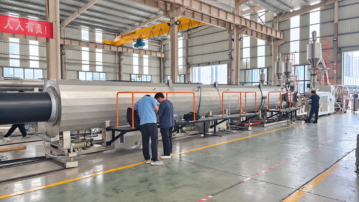
A PVC pipe production line is an integrated sequence of machinery that converts PVC resin compound into finished pipes through six core stages: raw material mixing, extrusion, vacuum calibration, cooling, haul-off and cutting, and stacking or bundling.
That definition sounds straightforward, yet the real-world execution involves dozens of engineering variables — from compound formulation and screw geometry to vacuum pressure and haul-off speed — all working in concert. Every stage affects what happens downstream, which is exactly why a surface-level overview rarely helps the people who actually specify, purchase, or operate this equipment.
Defining the PVC Pipe Production Line
A common misconception is that a PVC pipe machine is a single device you plug in and run. In reality, a plastic pipe production line is an ecosystem of interdependent units arranged in sequence. A typical line includes a twin screw extruder, a die head, a vacuum calibration and cooling tank, a haul-off machine, a cutter, and often a belling machine or automatic stacker. Remove or misconfigure any one of these units, and the entire system's output quality suffers.
Think of it this way: the extruder melts and homogenizes the PVC compound, the die head shapes it into a hollow profile, the vacuum calibration tank locks in dimensional accuracy while cooling water solidifies the pipe wall, the haul-off pulls the pipe at a controlled speed, and the cutter sections it to length. Each unit hands off a semi-finished product to the next, and the performance tolerances are tight. Wall thickness consistency, surface smoothness, ovality — all depend on how well these machines communicate through speed synchronization and process feedback.
Who This Guide Serves
This guide is built for three distinct readers, each with different stakes in how PVC pipes are manufactured:
- Technical engineers evaluating equipment specifications — you'll find component-level breakdowns, extruder type comparisons, and a troubleshooting matrix for common production defects.
- Plant managers and business decision-makers planning capacity or new factory setups — you'll gain clarity on line configurations, automation options, and practical investment planning frameworks.
- Quality managers seeking deeper process understanding — you'll discover how upstream choices in compound formulation and mixing directly influence the dimensional and surface quality of finished pipes.
The tone throughout is educational and vendor-neutral. Rather than steering you toward a specific manufacturer of PVC pipe equipment, the goal is to arm you with enough technical depth to ask better questions, compare offerings with confidence, and make decisions grounded in process knowledge rather than sales brochures.
In the sections ahead, you'll walk through raw material formulation, the often-overlooked mixing and compounding stage, a full component breakdown of the production line, a head-to-head comparison of extruder types, defect troubleshooting, line variants for UPVC, CPVC, and PVC-O pipes, and finally, automation features alongside investment planning guidance. Each stage builds on the last — because in a PVC pipe production line, nothing operates in isolation.
The journey begins where every pipe begins: with the resin and the additives that determine everything from melt behavior to long-term mechanical performance.
PVC Raw Materials and Compound Formulation Essentials
The resin and additives you choose before a single granule enters the extruder dictate nearly everything that follows — melt stability inside the barrel, surface finish on the pipe, and whether that pipe survives decades underground or fails prematurely. Yet compound formulation is the stage most equipment guides skip entirely. For anyone operating or investing in a pipe production line, this is foundational knowledge.
PVC Resin Grades and K-Value Selection
PVC resin is not a one-size-fits-all material. Grades are differentiated by molecular weight, and the industry-standard shorthand for that molecular weight is the K-value (also called K-number). Derived from intrinsic viscosity measurements using the Fikentscher equation, the K-value directly influences melt viscosity, mechanical strength, and processing behavior. A higher K-value means higher molecular weight — stronger pipes, but more demanding processing conditions.
Here is the practical breakdown for pipe production. Resins in the K65 to K67 range are the most common choice for pressure-rated PVC pipe, offering a strong balance between tensile strength and processability. Resins at K70 and above deliver even greater mechanical strength for high-pressure applications, though they require higher processing temperatures, longer fusion times, and more robust mixing equipment. On the other end, K57 to K60 resins — lower molecular weight, easier flow — suit injection-molded fittings rather than extruded pipe.
Why does this matter for your PVC machine setup? A resin with higher melt viscosity demands more torque from the extruder, tighter thermal control, and a formulation tuned to compensate for reduced flow. Selecting the wrong K-value for your target product creates a cascade of problems — from inconsistent wall thickness to surface roughness — that no amount of downstream adjustment can fully correct.
Essential Additives and Their Functions
Pure PVC resin is thermally unstable and nearly impossible to extrude on its own. It needs a carefully balanced cocktail of additives, each serving a specific role in the compound. Think of these additives as the supporting cast that allows the resin to perform under the heat and shear of a plastic pipe production line.
| Additive Category | Function in the Compound | Typical Examples |
|---|---|---|
| Heat Stabilizers | Prevent thermal degradation during processing; absorb HCl released at elevated temperatures | Calcium-zinc (Ca-Zn) systems, tin-based stabilizers, lead-based (being phased out) |
| Internal Lubricants | Reduce friction between PVC molecular chains, improving melt flow | Glycerol monostearate, oxidized polyethylene wax |
| External Lubricants | Reduce adhesion between the melt and metal surfaces of the barrel, screw, and die | Paraffin wax, polyethylene wax |
| Impact Modifiers | Improve toughness and resistance to brittle fracture, especially at low temperatures | Chlorinated polyethylene (CPE), acrylic impact modifiers (ACR) |
| Calcium Carbonate Fillers | Reduce material cost; can improve stiffness and dimensional stability at controlled loading levels | Ground calcium carbonate (GCC), precipitated calcium carbonate (PCC) |
| Processing Aids | Promote fusion, improve melt elasticity and surface finish | Acrylic processing aids (e.g., ACR-type polymers) |
One trend worth noting: the global shift toward lead-free stabilizer systems. Calcium-zinc stabilizers have become the dominant replacement in many markets, driven by regulatory pressure and end-user demand for safer piping materials. Tin-based stabilizers remain common in certain regions, particularly for pressure pipe where proven long-term performance data is valued. If you are sourcing compound formulations from a plastic pipe production line supplier, confirming the stabilizer system is an essential early conversation.
Pressure Pipe vs. Non-Pressure Pipe Formulations
Not every PVC pipe carries pressurized water, and the formulation reflects that reality. Pressure-rated pipes — used in water mains and irrigation systems — typically call for K67 or higher resin grades, lower filler content, and robust stabilizer packages designed to maintain long-term hydrostatic strength. Impact modifiers are carefully dosed to preserve toughness without sacrificing the stiffness that pressure applications demand.
Non-pressure pipes for drainage, sewage, or electrical conduit allow more flexibility. Lower K-value resins (K65 is common), higher filler loading to reduce cost, and less stringent stabilizer requirements are all typical. The processing window is generally wider, which can translate to faster extrusion speeds and simpler machine settings.
The key takeaway? Formulation is not an afterthought — it is the first engineering decision in the entire production sequence. A perfectly calibrated PVC machine running a poorly formulated compound will still produce substandard pipe. Get the recipe right, and every downstream unit benefits from a stable, predictable melt.
That stable melt, however, does not appear by magic. It depends entirely on how thoroughly the resin and additives are blended before they ever reach the extruder — a step that introduces its own set of critical process variables.
The Mixing and Compounding Stage Before Extrusion
You have the right resin, the right stabilizer package, and impact modifiers measured to the gram — yet dumping them all into an extruder without proper pre-mixing would be a recipe for disaster. The mixing and compounding stage is where individual raw materials become a unified, free-flowing dry blend capable of melting evenly under the heat and shear of extrusion. Skip this step or execute it poorly, and no machine PVC processors rely on downstream can compensate for the inconsistency baked into the compound.
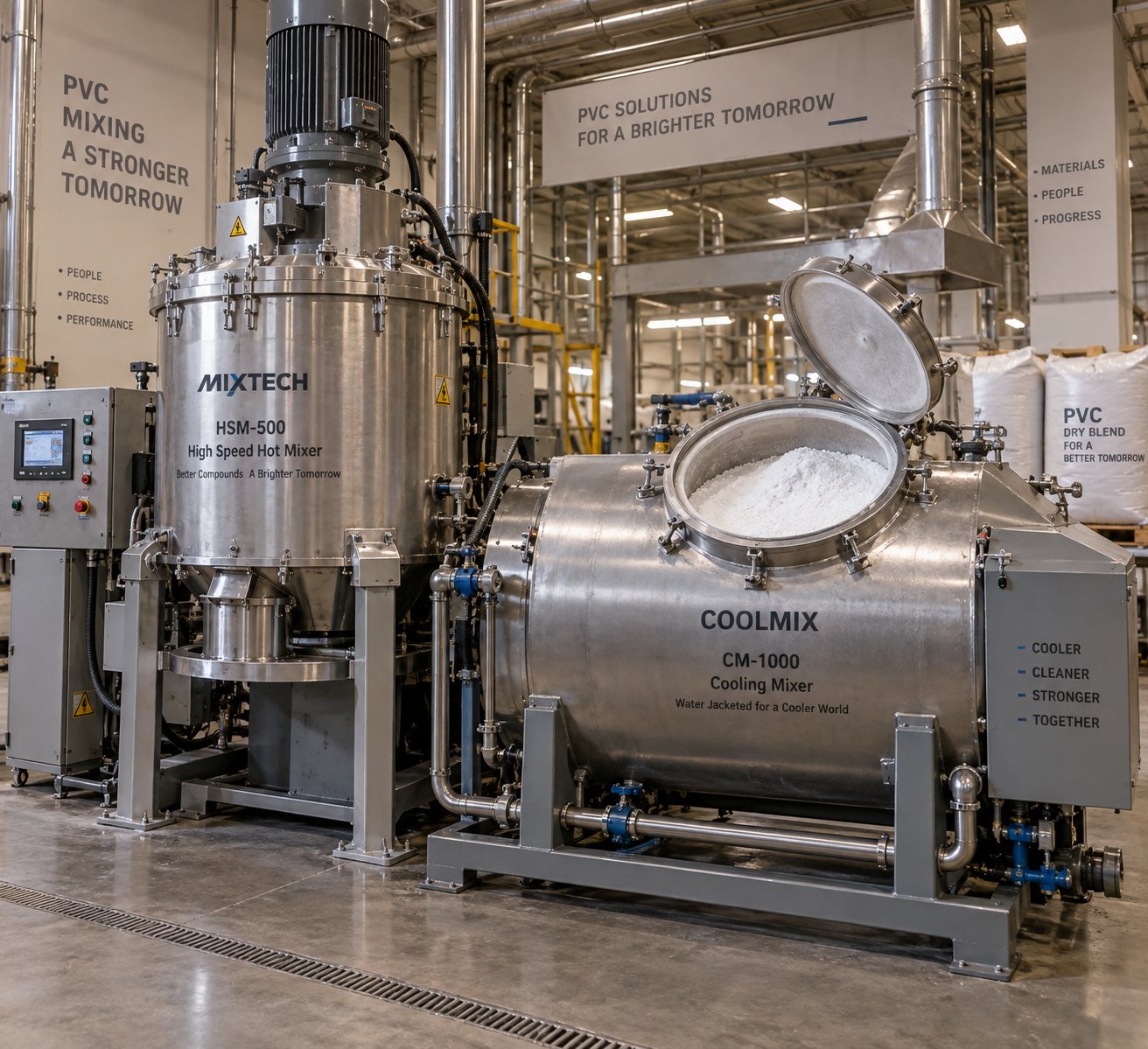
Most rigid PVC pipe operations use a two-stage batch mixing process: a hot mixer (high-speed mixer) followed immediately by a cooling mixer. Together, these two units transform a loose collection of powders, granules, and pellets into a homogeneous dry blend with controlled particle size, adequate apparent density, and a precise degree of pre-plasticization. Understanding what happens inside each mixer — and why the sequence matters — is essential for anyone evaluating a PVC pipe manufacturing machine supplier or troubleshooting quality issues on an existing line.
Hot Mixer and Cooling Mixer Functions
The hot mixer is a high-speed, vertically oriented vessel fitted with multi-blade agitators spinning at high angular velocity. There is no external heater in most designs — the heat comes entirely from friction generated between the blades, the raw materials, and the vessel walls. As blade speed drives the temperature upward, several things happen simultaneously inside the pot:
- PVC particles shatter under shear force, increasing their specific surface area and generating strong electrostatic attraction toward smaller additive particles.
- Low-melting-point additives — processing aids and certain lubricants — soften and coat the surfaces of PVC grains, acting as adhesive bridges for inorganic fillers like calcium carbonate and titanium dioxide.
- Once the compound exceeds PVC's glass transition temperature of roughly 87 °C, resin particles begin to soften from the outside inward, reaching a controlled level of pre-plasticization that improves later fusion in the extruder.
- Moisture and low-molecular-weight volatiles are driven off, preventing bubbles, degradation, and surface defects during extrusion.
For rigid PVC pipe and profile formulations, the hot mix discharge temperature is typically set around 120 °C. Setting it too low leaves small-particle-size components — calcium carbonate, TiO₂ — inadequately bonded to the PVC grains, resulting in a dry blend prone to static buildup, poor flowability, and even material stratification during pneumatic conveying to the extruder hopper. Setting it too high over-plasticizes the compound and prematurely consumes heat stabilizer, narrowing the processing window and potentially degrading weathering performance in the finished pipe.
The cooling mixer receives the hot discharge immediately. This is a larger, low-speed horizontal or vertical vessel surrounded by a water-cooled jacket. Its job is straightforward but critical: bring the compound temperature down — typically to 40–45 °C — before the dry blend enters storage. Why the urgency? A hot dry blend sitting in a storage silo continues to absorb heat from its own mass. Without adequate cooling, the center of the stored material can degrade, turning pink or showing early signs of thermal breakdown. Cooling water temperature is usually controlled between 13 °C and 15 °C to maximize heat extraction speed, since faster cooling yields higher apparent density and better flow characteristics.
After cooling, the dry blend benefits from a resting period in storage — ideally at least 12 hours. This standing time dissipates residual static charge accumulated during high-speed mixing, further improves apparent density, and homogenizes the blend. Manufacturers who skip or shorten this curing step often encounter "bridging" in feed hoppers or inconsistent extrusion behavior, especially on parallel twin-screw systems.
Batch Mixing vs. Continuous Mixing
The two-stage hot-and-cold process described above is inherently a batch operation — a fixed volume of material is loaded, mixed to the target temperature, discharged, cooled, and the cycle repeats. Batch mixing remains dominant across most PVC pipe plants for good reason: it offers precise control over each charge, easy traceability for quality records, and flexibility to change formulations between batches with minimal crossover contamination.
For high-volume plastic energy pipe making line operations producing a single formulation around the clock, continuous mixing systems present an alternative. These use a series of interconnected mixers or a long continuous-path blender that feeds directly into the extruder hopper. The advantage is throughput — no downtime between batches. The trade-off is a higher capital investment, more complex process control, and less flexibility when switching between compound recipes. Most small-to-mid-scale producers find batch mixing the practical choice, while continuous systems earn their place in dedicated, high-output facilities.
How Compounding Quality Affects Downstream Production
Here is the connection many equipment guides miss entirely: mixing quality is the single largest upstream variable affecting extrusion stability. A poorly compounded dry blend does not just cause minor inconveniences — it cascades through every downstream unit in the production line.
When additive dispersion is uneven, the melt inside the extruder barrel develops inconsistent viscosity. Some zones flow freely while others resist, creating pressure fluctuations at the die head. Those fluctuations translate directly into wall thickness variation, rough inner surfaces, and dimensional instability in the finished pipe. Fish eyes — those small, hard spots visible on the pipe surface — are almost always traceable to undispersed gels or agglomerates that originated in the mixing stage.
Experienced operators know to check the dry blend before it ever reaches the extruder. The key indicators of proper compounding include:
- Uniform color — no streaks, no pink discoloration, consistent whiteness across the entire batch, indicating even additive distribution and appropriate pre-plasticization
- Correct discharge temperature — the hot mix reached its target (around 120 °C for UPVC) and the cooling mix brought it down to 40–45 °C, confirming the thermal cycle completed as designed
- Absence of agglomerates — no visible lumps, hard particles, or oversized clusters when the blend is inspected through a sieve; sieve residue within specification
- Good flowability — the dry blend pours freely through a standard funnel without hesitation or bridging, reflecting that small-particle-size components have been properly absorbed into larger PVC grains
- Adequate apparent density — typically reaching around 0.60–0.62 g/ml for standard UPVC formulations after hot and cold mixing, up from roughly 0.55 g/ml before mixing
If any of these indicators fall outside acceptable ranges, the corrective action belongs here — at the mixer — not further down the line. Adjusting extruder temperatures or screw speed to compensate for a bad dry blend is a losing strategy that usually introduces new defects while masking the original problem.
This stage is, frankly, underestimated across the industry. Many plant managers invest heavily in the extruder, the die head, and downstream equipment while treating the mixing unit as a commodity. Yet the reality is unambiguous: a well-formulated, properly compounded dry blend is the foundation on which the entire production line's performance rests. Every unit that follows — from the feeding system to the automatic stacker — performs better when it receives consistent, high-quality input material.
With a uniform dry blend secured, the focus shifts to the machinery that transforms that powder into a continuous, precisely shaped pipe — a sequence of interdependent units where each component's role and configuration directly affect the final product.
Complete Component Breakdown of the Production Line
A uniform dry blend is only as valuable as the machinery that transforms it. Every pipe making machine in the sequence — from the moment compound enters the feeding hopper to the instant a finished length rolls onto the stacker — performs a distinct mechanical or thermal function that the next unit depends on. Misunderstand one component's role, and you risk specifying plastic pipe equipment that bottlenecks the entire operation. Here is the full walkthrough, unit by unit.
The journey starts at the feeding system. Gravimetric or volumetric feeders meter the dry blend from storage into the extruder at a controlled, consistent rate. Sounds simple, yet feed rate stability directly governs melt pressure consistency inside the barrel. Starve the extruder and you get pressure dips that show up as wall thickness variation; overfeed it and you risk overloading the drive motor or compacting material in the feed zone. Gravimetric feeders — which dose by weight rather than volume — offer superior consistency, especially when apparent density shifts slightly between batches.
Extruder and Die Head — The Heart of the Line
The extruder melts, homogenizes, and pressurizes the PVC compound, turning a loose powder into a dense, uniform melt stream. Inside the heated barrel, rotating screws generate shear and frictional heat that fuse the compound while conveying it forward through carefully zoned temperature sections. The result is a fully plasticized melt delivered at stable pressure to the die head.
The die head shapes that melt into a hollow, tubular profile. It distributes material evenly around a central mandrel so the emerging pipe has uniform wall thickness across its entire circumference. Die design — particularly the flow channel geometry and land length — has an outsized impact on surface finish and dimensional accuracy. A well-engineered die minimizes dead spots where material can stagnate and degrade, which is critical for PVC's shear-sensitive processing behavior.
Extruder type selection — conical twin-screw, parallel twin-screw, or single-screw — is a decision significant enough to warrant its own detailed comparison, which follows in the next section.
Vacuum Calibration and Cooling Systems
When the soft, hot pipe exits the die, it has a shape but zero structural rigidity. Gravity, internal stresses, and uneven cooling could deform it within seconds. The vacuum calibration tank prevents that. It uses negative pressure — typically in the range of 0.02 to 0.06 MPa — to pull the still-pliable extrudate outward against a precision-machined sizing sleeve, while water simultaneously cools and solidifies the outer skin.
Three interacting variables control final pipe dimensions inside this tank:
- Vacuum level — higher vacuum presses the pipe more firmly against the sleeve, producing a tighter outer diameter. Too much vacuum, however, can thin the wall or create internal surface voids.
- Water temperature — cooler water (commonly 15 °C to 20 °C) accelerates solidification, locking in dimensions faster. Excessively cold water induces internal stress that can cause brittleness or post-production warping.
- Sizing sleeve dimensions — the sleeve's inner diameter defines the pipe's target outer diameter, with tolerances often held within ±0.02 mm on chrome-plated interior surfaces.
After initial calibration, the pipe passes through one or more spray or immersion cooling tanks that continue extracting heat from the pipe wall. These additional cooling stages are essential because only the outer skin solidifies in the vacuum tank — the core of the wall remains warm and soft. If the pipe reaches the haul-off before the full wall cross-section has cooled below its deformation threshold, downstream pulling forces will stretch or distort it. Line speed, in many cases, is actually limited not by the extruder's output capacity but by available cooling length.
Haul-Off, Cutting, and Stacking Equipment
The haul-off unit grips the cooled pipe and pulls it through the entire downstream section at a precisely controlled speed. This speed — relative to extruder output — directly determines wall thickness. Even small oscillations in haul-off velocity produce repeating thickness patterns in the finished product, which is why drive stability and grip consistency matter enormously.
Two common designs dominate. Caterpillar-type haul-offs use rubber-padded track belts that clamp around the pipe, distributing pulling force over a long contact area — ideal for medium to large diameter pipes. Belt-type haul-offs serve similar functions for smaller diameters and lighter profiles.
At the end of the line, a cutter sections the continuous pipe into specified lengths. Planetary cutters rotate a blade around the pipe circumference while traveling with it, producing chip-free cuts well suited for larger diameters. Chipless cutters use a similar orbiting principle but are optimized for smaller diameters — typically under 110 mm — where speed and clean end faces are priorities. Finally, an automatic stacker or bundler collects cut lengths, organizes them into bundles, and prepares them for storage or shipment, reducing manual labor and handling damage.
One optional addition worth noting: automatic socketing (belling) machines can be integrated inline between the cutter and stacker. These units heat one end of the cut pipe and form it into a socket joint, eliminating the need for separate couplings during installation. For any PVC tube manufacturer targeting municipal water or drainage markets, inline belling can significantly increase the finished product's value.
The table below summarizes every major component, its core function, and the key specification to evaluate when configuring a line:
| Component | Primary Function | Key Specification to Evaluate |
|---|---|---|
| Feeding System | Meters dry blend into the extruder at a consistent rate | Dosing accuracy (gravimetric vs. volumetric); throughput capacity (kg/hr) |
| Extruder | Melts, homogenizes, and pressurizes PVC compound | Screw type and diameter; output rate; torque capacity; number of heating zones |
| Die Head | Shapes the melt into a tubular pipe profile | Pipe diameter range; flow channel design; ease of centering adjustment |
| Vacuum Calibration Tank | Sizes and initially cools the pipe using negative pressure and water | Vacuum range (MPa); sizing sleeve tolerance; tank length |
| Spray/Immersion Cooling Tanks | Continue extracting heat to fully solidify the pipe wall | Total cooling length; water temperature control; flow rate |
| Haul-Off Unit | Pulls the pipe at controlled speed through the downstream line | Clamping force; speed range and stability; contact type (caterpillar or belt) |
| Cutter | Sections continuous pipe into specified lengths | Cutting type (planetary or chipless); diameter range; cut-length accuracy |
| Stacker/Bundler | Collects, organizes, and bundles finished pipe lengths | Stacking capacity; automation level; bundle size range |
| Socketing/Belling Machine (optional) | Forms a socket joint at one end of cut pipe lengths | Socket depth and diameter range; heating method; cycle time |
Every unit in this sequence is mechanically straightforward on its own. The real engineering challenge — and the factor that separates high-performing lines from mediocre ones — lies in synchronization. Feed rate, screw speed, melt pressure, haul-off velocity, and cutter timing must all operate in lockstep. A mismatch at any point ripples through the entire system.
Of all these components, the extruder demands the most careful selection because its design fundamentally shapes how the PVC compound is processed. Conical twin-screw, parallel twin-screw, and single-screw configurations each bring distinct advantages and trade-offs — a comparison that deserves its own focused analysis.
Conical vs. Parallel vs. Single-Screw Extruders Compared
The extruder is the single most consequential equipment decision in any PVC pipe production line — not because it costs the most, but because its screw geometry dictates how gently or aggressively your compound is plasticized, how much output you can sustain, and how wide your processing window truly is. Three fundamental configurations compete for that role: conical twin-screw, parallel twin-screw, and single-screw. Each brings a different engineering philosophy to the same challenge — converting a shear-sensitive PVC dry blend into a stable, homogeneous melt without degrading it.
Choosing the wrong type does not just reduce efficiency. It can limit your product range, narrow your quality margins, and create recurring defects that no amount of downstream tuning can resolve. So how do you decide?
Conical Twin-Screw Extruders for PVC Processing
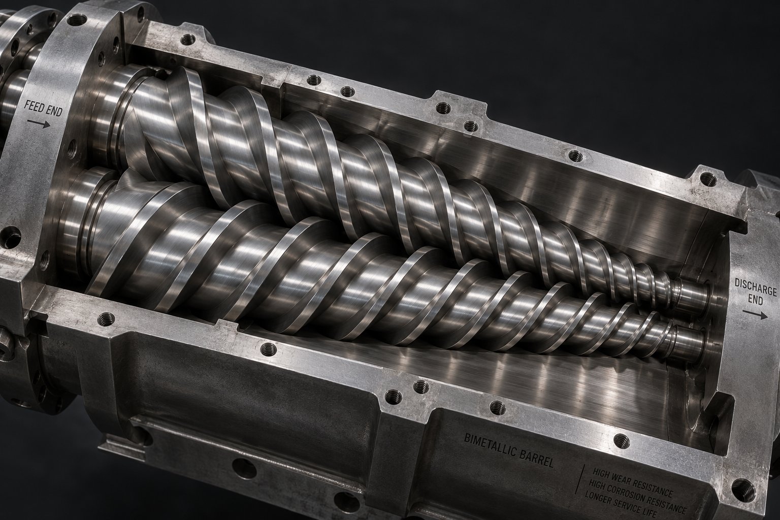
Walk into most rigid PVC pipe factories worldwide and you will find a conical twin-screw extruder at the heart of the line. There is a reason for that dominance. The conical design features two counter-rotating, intermeshing screws that taper from a larger diameter at the feed inlet to a smaller diameter at the discharge end. This geometry creates a natural compression ratio built directly into the screw profile — no complex zoning required.
Why does that matter for PVC specifically? Rigid PVC is notoriously sensitive to shear and heat. Excessive mechanical energy input degrades the polymer, releasing hydrochloric acid that accelerates further breakdown. The conical twin-screw sidesteps this problem through several inherent advantages:
- Gentle shear profile — the counter-rotating screws create C-shaped enclosed chambers that convey material forward with controlled, low-intensity shear. Typical operating speeds sit between 30 and 150 rpm, compared to 400-plus rpm for co-rotating parallel systems. Less shear means less frictional heat, which directly reduces the risk of thermal degradation.
- High feeding efficiency — the larger inlet diameter provides a generous feed opening that accepts low-bulk-density PVC dry blend easily, while the tapering barrel progressively compresses the material. This natural compression eliminates the need for force-feeding mechanisms in most standard applications.
- Excellent pressure generation — as the screws taper toward the discharge, the material is compacted into an increasingly smaller volume. This builds the melt pressure needed to push material through the die head without relying on excessive screw speed.
- Stable plasticizing performance — the combination of gentle shear, gradual compression, and low rotational speed produces a remarkably consistent melt viscosity. For pressure-rated pipe where wall thickness uniformity is non-negotiable, that stability is everything.
The conical configuration also delivers high torque at low speed — a mechanical advantage stemming from the larger root diameter at the feed end, which provides ample space for robust gears and bearings in the gearbox. This makes conical machines particularly well suited for processing highly filled PVC compounds and formulations with higher K-value resins that demand more work to plasticize.
One practical consideration that experienced plant operators know well: the screw and barrel assembly in a conical extruder is a wear component. Over thousands of production hours, the nitrided or bimetallic surfaces gradually lose their dimensional precision, affecting melt quality and output consistency. When replacement or upgrade time arrives, sourcing barrels from a specialist matters. NANHAIYA's conical twin screw barrels, for example, are purpose-built for PVC pipe, profile, board, and WPC extrusion applications — offering custom and replacement options designed to restore stable plasticizing performance without the lead times or compatibility risks of generic alternatives.
Parallel Twin-Screw and Single-Screw Alternatives
Parallel twin-screw extruders take a fundamentally different approach. Their two screws maintain a constant diameter from feed to discharge, typically in a co-rotating, intermeshing arrangement. This design excels at intensive mixing — the overlapping flight geometry forces material through high-shear zones repeatedly, creating an "infinity-pattern" flow path that disperses additives and fillers with exceptional uniformity.
For PVC pipe production, parallel twin-screw machines occupy a specific niche. They offer greater flexibility in screw design — segments can be rearranged or extended (from 22D to 33-36D length-to-diameter ratios, for instance) to accommodate different formulations or increase output by stretching the pitches of the C-ring chambers. Advances in finite element method (FEM) gearbox design have also closed the historical torque gap, giving parallel machines high reliability for demanding applications. For larger-diameter PVC pipes, parallel extruders are increasingly favored because they provide a wider processing window — critical when achieving sufficient gelation for pressure pipe testing while avoiding over-fusion in the vent zone.
The trade-off? Parallel systems generate more shear heat at their higher operating speeds, demanding more precise thermal management for heat-sensitive PVC. Their processing window, while wider at larger sizes, requires more operator expertise to optimize. Capital costs tend to run higher due to the complex transmission systems and high-speed capabilities built into these machines.
Single-screw extruders represent the simplest configuration — one rotating screw inside a heated barrel. They are valued for straightforward operation, lower initial cost, and easy maintenance. In PVC pipe applications, however, their role is limited. A single screw lacks the intermeshing action that twin-screw designs use for thorough mixing and controlled conveying. This makes single-screw machines best suited for smaller-diameter, non-pressure applications — think electrical conduit or lightweight drainage pipe — where output demands are moderate and compound formulations are uncomplicated. Running a challenging high-K-value pressure pipe formulation through a single-screw extruder typically results in inconsistent plasticization and narrow processing margins.
Choosing the Right Extruder Configuration
The decision ultimately comes down to three variables: what pipe you need to produce, how much of it, and what compound you are running. Consider these practical decision criteria:
- Pipe diameter range — conical twin-screw extruders dominate for small-to-medium diameters (roughly 16 mm to 400 mm). For large-diameter pressure pipe (400 mm and above), parallel twin-screw machines increasingly offer processing advantages due to their extensible screw length and wider gelation window.
- Output requirements — if your target throughput exceeds what a conical machine can deliver at safe operating speeds, a parallel extruder's ability to increase output by extending screw length — without increasing diameter — provides a scalable path forward.
- Compound type — dedicated PVC operations running consistent formulations benefit from the conical's simplicity and stable performance. Plants handling varied formulations, multiple resin grades, or frequent recipe changes may value the parallel's modular screw configurability.
- Pressure vs. non-pressure pipe — pressure-rated pipe demands tighter gelation control and absolute melt consistency, where both conical and parallel twin-screw designs can deliver. Single-screw extruders are generally unsuitable for pressure pipe production at commercial scale.
The comparison table below distills these differences across the parameters that matter most when configuring a plastic water pipe making machine or any PVC pipe extrusion setup:
| Parameter | Conical Twin-Screw | Parallel Twin-Screw | Single-Screw |
|---|---|---|---|
| Typical PVC Pipe Applications | Rigid UPVC pipe and profiles (16-400 mm); dedicated PVC lines | Medium-to-large diameter pipe (including 400 mm+); varied formulations | Small-diameter conduit; non-pressure drainage pipe |
| Typical Screw Speed Range | 30-150 rpm | 400-900 rpm (co-rotating) | 20-150 rpm |
| Shear Characteristics | Low, gentle; C-shaped chamber conveying | High intensity; infinity-pattern mixing | Moderate; limited mixing capability |
| Output Scalability | Increase requires larger diameter machine | Extend screw length (22D to 36D) to boost output | Limited by single-channel conveying |
| Energy Efficiency | High at low speeds; efficient for standard PVC | Higher energy at high speeds; offset by throughput gains | Low energy draw; lowest overall throughput |
| Processing Window for PVC | Reliable but can be narrow at high outputs | Wider, especially for large pipe and varied gelation targets | Narrow; limited thermal and mixing control |
| Suitability for Pressure Pipe | Excellent for small-to-medium diameters | Excellent, especially for large diameters | Generally unsuitable at commercial scale |
| Capital Cost | Moderate | Higher (complex gearbox and drive systems) | Lowest |
No single extruder type wins across every scenario. The conical twin-screw remains the workhorse of PVC machinery worldwide — reliable, proven, and purpose-built for the polymer's thermal sensitivities. Parallel twin-screw systems earn their place where output demands, pipe diameters, or formulation complexity push beyond what conical geometry can comfortably deliver. Single-screw machines serve the entry-level or supplementary role, handling simpler products at lower investment.
Selecting the right extruder, however, only prevents problems at the plasticizing stage. What about the defects that still emerge during production — rough surfaces, uneven walls, discoloration? These issues have specific root causes and equally specific fixes, and a structured troubleshooting approach can save hours of trial-and-error on the factory floor.
PVC Pipe Defects and Solutions: A Practical Troubleshooting Guide
Even a well-configured extrusion line staffed by experienced operators encounters defects. The difference between a high-performing plant and a struggling one is not the absence of problems — it is how quickly and systematically those problems get diagnosed. PVC pipe extrusion troubleshooting is often treated as tribal knowledge passed between shift supervisors, but a structured approach eliminates guesswork and prevents the same issues from recurring batch after batch.
Most defects trace back to one of four areas: compound formulation, thermal processing parameters, mechanical tooling condition, or downstream equipment settings. Identifying which area is responsible — before making adjustments — is the foundation of effective PVC pipe production quality control.
Surface Defects and Their Root Causes
Surface quality is the first thing an inspector notices, and it often reveals deeper process instability. A rough inner surface typically signals insufficient plasticizing — the compound did not receive enough heat or shear energy to form a fully homogeneous melt before reaching the die. Low melt temperature, excessive external lubricant delaying fusion, or a worn mandrel with scratches or degraded material buildup are the usual culprits. Increasing barrel temperature gradually, verifying lubricant balance, and inspecting the mandrel surface usually resolve it.
A rough or matte outer surface points in a different direction. Damaged die lips — nicks, scratches, or carbon deposits on the exit face — physically score the surface as the melt passes over them. Incorrect vacuum calibration that fails to press the pipe firmly against the sizing sleeve can also leave the exterior looking dull or textured. Regular die polishing and verifying vacuum pressure stability are straightforward corrective steps.
Fish eyes deserve special attention because they frustrate operators more than almost any other defect. These small, hard circular spots scattered across the pipe surface are almost always undispersed gels — resin particles or additive agglomerates that never fully fused during mixing or extrusion. The root causes span multiple stages: poor fusion from inadequate shear, calcium carbonate agglomerates from insufficient hot-mix temperature, contaminated raw materials, or an imbalanced lubricant system that delays gelation. Solving fish eyes requires working backward — checking the dry blend for lumps and uniform color before blaming the extruder.
Discoloration or yellowing is the visible signature of thermal degradation. When PVC is exposed to excessive temperature or prolonged residence time inside the barrel, die head, or adapter, the polymer breaks down and releases hydrochloric acid — accelerating further decomposition. Dead spots in flow channels where material stagnates are a frequent contributor. Corrective actions include reducing barrel zone temperatures, verifying that the stabilizer dosage in the formulation is adequate, cleaning die components to eliminate material hang-up, and ensuring the extruder is not running at unnecessarily low throughput relative to its barrel volume.
Dimensional and Structural Defects
Uneven wall thickness — thicker on one side, thinner on the other — is among the most critical defects because it directly compromises pressure-bearing capacity. The primary cause is die and mandrel misalignment, where the two are not perfectly concentric. Inconsistent haul-off speed creates a secondary effect, cyclically stretching and relaxing the soft pipe wall. Uneven temperature distribution across the die head can also cause the melt to flow faster on one side than the other. Precise die centering during setup, uniform heating zone calibration, and stable haul-off drive control address the root causes.
Ovality — the pipe cross-section becoming elliptical rather than perfectly round — makes joint sealing unreliable and can lead to field failures. Insufficient vacuum in the calibration tank is the most common trigger: without adequate negative pressure, the soft extrudate does not seat firmly against the sizing sleeve. Non-uniform cooling spray patterns compound the issue by allowing one side to solidify and shrink faster than the other. Haul-off misalignment and inadequate pipe support between rollers can also pull the warm pipe out of round before it fully hardens.
Warping or post-extrusion deformation often appears after the pipe is cut and stacked, puzzling operators who saw perfectly round pipe exiting the line. The cause is usually internal residual stress from excessively rapid or uneven cooling. When the outer skin solidifies while the core remains hot, differential shrinkage locks in stress that releases gradually over hours or days. Maintaining controlled, gradual cooling water temperatures and ensuring sufficient total cooling length before cutting are the primary preventive measures.
The troubleshooting matrix below consolidates these pvc pipe defects and solutions into a quick-reference format for production teams:
| Defect | Root Cause(s) | Corrective Action |
|---|---|---|
| Rough inner surface | Insufficient plasticizing; low melt temperature; damaged or contaminated mandrel | Increase barrel temperature gradually; verify lubricant balance; clean and polish mandrel |
| Rough or matte outer surface | Die lip damage (nicks, carbon deposits); inadequate vacuum calibration | Polish or replace die components; verify vacuum pressure stability and sizing sleeve condition |
| Fish eyes | Undispersed gels from poor mixing; calcium carbonate agglomerates; contamination; lubricant imbalance delaying fusion | Verify hot-mix discharge temperature and blend uniformity; check filler moisture and particle size; adjust lubricant ratio; inspect screen pack |
| Discoloration / yellowing | Thermal degradation from excessive temperature or residence time; dead spots in flow channels; insufficient stabilizer | Reduce barrel/die temperatures; clean adapter and die to eliminate material hang-up; review stabilizer dosage; increase throughput to reduce residence time |
| Uneven wall thickness | Die-mandrel misalignment; inconsistent haul-off speed; uneven die head temperature | Re-center die and mandrel using centering bolts; calibrate haul-off drive; verify all heating zones are functioning uniformly |
| Ovality | Insufficient vacuum in calibration tank; non-uniform cooling spray; haul-off misalignment; inadequate pipe support | Increase and stabilize vacuum pressure; clean spray nozzles for even coverage; align all downstream equipment to centerline; adjust roller spacing |
| Warping / post-extrusion deformation | Residual internal stress from rapid or uneven cooling | Increase total cooling length; control water temperature for gradual solidification; ensure uniform spray coverage around pipe circumference |
Bookmark this matrix — it compresses what often takes hours of trial-and-error into a structured diagnostic starting point. When a defect appears, resist the impulse to adjust a single parameter blindly. Instead, identify the defect category, match it to the most likely root cause, and verify before making changes. A single corrective adjustment in the right place beats five random tweaks across the line.
Worth noting for operations pursuing continuous improvement: many of these defects interact. Thermal degradation, for instance, can produce both discoloration and fish-eye-like burned particles simultaneously. Uneven wall thickness combined with rapid cooling creates the conditions for both ovality and warping. Effective quality control means treating the production line as an interconnected system — the same principle that applies when adapting a standard UPVC extrusion setup for more demanding pipe types like CPVC or molecularly oriented PVC-O.
Production Line Variants for UPVC, CPVC, and PVC-O Pipes
Understanding the difference between UPVC and CPVC pipe production — and where PVC-O fits in — matters because each variant places fundamentally different demands on the same extrusion hardware. A line optimized for standard UPVC cannot simply run CPVC resin at higher temperatures and produce acceptable pipe. The chemistry is different, the thermal behavior is different, and the downstream requirements shift accordingly. The same applies to PVC-O, which introduces an entirely separate orientation step that transforms the pipe's mechanical profile.
All three share a polyvinyl chloride backbone. Yet their processing paths diverge in ways that affect every unit from the extruder barrel to the cooling tank — and understanding those divergences helps you specify the right equipment from the start rather than retrofitting later.
UPVC Pipe Production — The Industry Standard
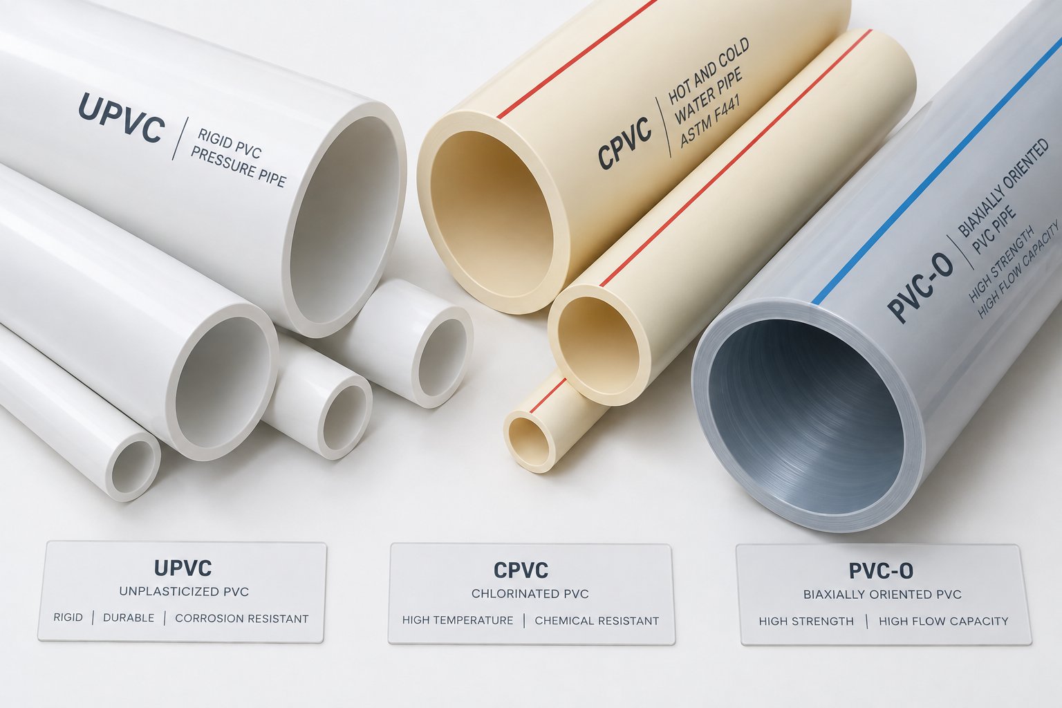
When someone references a "PVC pipe production line" without further qualification, they almost always mean a UPVC pipe production line. Unplasticized PVC — rigid, strong, and cost-effective — accounts for the vast majority of extruded PVC pipe globally. The "U" simply means no plasticizers have been added to soften the material, so the pipe retains its full inherent stiffness and mechanical strength.
UPVC processing temperatures typically range from 160 °C to 200 °C across the extruder barrel zones, with melt temperatures at the die head generally falling between 180 °C and 195 °C depending on formulation, pipe diameter, and extruder type. This window is well understood and forgiving enough that most standard twin-screw extrusion lines handle it comfortably.
Typical UPVC applications include:
- Drainage and sewage systems — non-pressure pipes with higher filler loading for cost efficiency
- Potable water mains — pressure-rated pipes using higher K-value resins and tighter quality control
- Electrical conduit — thin-walled, smaller-diameter pipe with simpler formulations
- Irrigation piping — both pressure and non-pressure variants depending on system design
Most production lines ship from equipment manufacturers pre-configured for UPVC by default. Screw geometry, barrel alloys, die head flow channels, and cooling tank lengths are all dimensioned around UPVC's well-documented melt behavior. This is the baseline — and the two variants below represent deliberate departures from it.
CPVC and PVC-O Lines — Specialized Configurations
CPVC — chlorinated polyvinyl chloride — is produced by subjecting standard PVC resin to a post-chlorination reaction that raises the chlorine content from roughly 57% to between 63% and 69%. That chemical modification dramatically increases the material's heat deflection temperature, allowing CPVC pipes to handle continuous service temperatures up to approximately 93 °C — well beyond UPVC's practical ceiling of around 60 °C.
What does this mean for a CPVC pipe extrusion line? Several critical adjustments are required:
- Higher processing temperatures — barrel zone temperatures for CPVC typically run 20 °C to 40 °C above UPVC settings, pushing into the 200 °C to 240 °C range. This demands more robust heating elements, better insulation, and a temperature control system capable of holding tighter tolerances, since CPVC's processing window between adequate fusion and thermal degradation is narrower than UPVC's.
- Greater melt viscosity — CPVC resists flow more stubbornly when molten, requiring extruders with higher torque capability and die heads engineered for increased back pressure. Screw designs may need modification to ensure adequate plasticization without generating excessive shear heat.
- Specialized stabilizer systems — CPVC formulations require stabilizers effective at elevated temperatures, and the entire additive package must be validated for the higher thermal exposure.
- Precise cooling control — because CPVC retains heat longer and is more sensitive to internal stress, cooling must be carefully graduated to avoid warping or residual strain in the finished pipe.
CPVC finds its niche in hot-water distribution, fire sprinkler systems, and industrial chemical piping where standard UPVC simply cannot survive the operating temperatures or chemical exposure.
PVC-O — molecularly oriented PVC — represents an entirely different production philosophy. Rather than modifying the chemistry, PVC-O transforms the physical structure of the pipe after extrusion. The pvc-o pipe manufacturing process begins with a standard UPVC extrusion, but then introduces a molecular orientation stage — either inline or offline — where the pipe is reheated to a precise temperature and subjected to controlled pressures and speeds that stretch and align the naturally random PVC molecular chains.
Imagine pulling a tangled pile of rope until every strand runs in the same direction. That alignment gives PVC-O pipes dramatically improved properties compared to standard UPVC of the same wall thickness:
- Impact resistance increases severalfold, making the pipe far more resistant to third-party damage during installation
- Tensile strength improves significantly, enabling higher pressure ratings at reduced wall thickness
- Fatigue resistance increases, extending service life under cyclic pressure loading
- Lighter weight per unit length — thinner walls carrying the same pressure rating means less raw material and easier handling
Specialized equipment is required for the orientation step. Companies like Molecor have developed inline machines that install directly after the extruder and use hot air to orient the molecules — an approach the company reports is more energy-efficient than older boiling-water methods. These systems can produce Class 500 PVC-O pipes (the highest classification under ISO standards) in diameters up to 1,200 mm. The orientation equipment, however, involves licensing agreements and significant capital investment beyond a standard extrusion line.
PVC-O targets pressurized water transmission — water mains, irrigation trunk lines, and fire suppression systems — where its combination of high pressure rating, low weight, and superior impact toughness delivers clear lifecycle cost advantages.
The table below captures the key differences across all three pipe types:
| Parameter | UPVC | CPVC | PVC-O |
|---|---|---|---|
| Processing Temperature Range | 160 °C – 200 °C (barrel zones) | 200 °C – 240 °C (barrel zones) | Standard UPVC extrusion + orientation at controlled reheat temperature |
| Key Applications | Drainage, sewage, potable water, conduit, irrigation | Hot-water distribution, fire sprinkler systems, industrial chemical piping | Pressurized water mains, irrigation trunk lines, fire suppression |
| Maximum Service Temperature | ~60 °C | ~93 °C | Similar to UPVC (~60 °C); advantage is mechanical, not thermal |
| Notable Equipment Modifications | None — standard line configuration | Higher-torque extruder; enhanced thermal control; modified screw design; specialized stabilizer system | Dedicated molecular orientation machine (inline or offline); licensing typically required |
| Pressure Rating Advantage | Standard — determined by wall thickness and resin grade | Similar to UPVC at equivalent wall thickness | Significantly higher pressure rating at reduced wall thickness |
Sustainability Considerations Across All Variants
Regardless of which pipe type you produce, a few sustainability practices apply broadly across the PVC pipe industry — and they increasingly influence both regulatory compliance and buyer preference.
First, production scrap and off-cuts from all three variants can typically be reground and reintroduced into the production line at controlled percentages. This closed-loop material recovery reduces raw material consumption and waste disposal costs. For UPVC, regrind ratios of 5% to 10% in fresh compound are common without measurable impact on pipe properties, though exact percentages depend on the application standard and end-use specification.
Second, the industry-wide shift toward lead-free stabilizer systems — particularly calcium-zinc formulations replacing legacy lead-based stabilizers — reflects growing environmental responsibility and regulatory pressure across global markets. This transition affects formulation and mixing parameters but does not fundamentally alter the production line hardware.
Third, modern extrusion lines increasingly feature energy-efficient servo drive motors and optimized barrel heating systems that reduce electricity consumption per kilogram of pipe produced. For plants running multiple lines around the clock, these efficiency gains compound into meaningful operational cost reductions and a smaller carbon footprint.
These sustainability-driven upgrades — material recycling, cleaner chemistry, smarter energy use — are not just environmental gestures. They directly improve operating economics, a point that becomes even more apparent when evaluating the automation and smart control technologies reshaping how modern production lines are monitored, managed, and justified as capital investments.
Automation, Smart Controls, and Investment Planning for PVC Pipe Lines
Energy-efficient drives and lead-free chemistry reduce operating costs on a per-kilogram basis. But the real multiplier — the factor that determines whether those gains hold steady across every shift, every batch, and every operator changeover — is how intelligently the production line monitors and adjusts itself. Automated PVC pipe manufacturing is no longer a luxury reserved for the largest factories. It has become the dividing line between plants that consistently hit quality targets and plants that chase defects reactively.
Equally important, and almost never discussed alongside equipment specifications, is the financial architecture behind the line itself. Understanding PVC pipe production line cost categories, staffing models, and facility requirements is what separates a sound capital decision from an expensive lesson in underspecification.
Automation Features That Improve Consistency and Yield
Imagine running a 24-hour production shift where every pipe length exits the cutter within tolerance — no manual interventions, no scrapped sections from startup surges, no operator-dependent quality variation. That is the practical promise of PVC extrusion line automation, and the technologies enabling it are well proven.
At the front end of the line, gravimetric dosing systems replace traditional volumetric feeders by measuring raw material by actual weight rather than volume. Why does this matter? PVC dry blend apparent density fluctuates slightly between batches. A volumetric feeder delivers a consistent volume regardless, which means the actual mass entering the extruder drifts up or down — producing pipes that are overweight (wasting expensive resin) or underweight (risking non-compliance). Gravimetric systems eliminate this uncertainty. As industry procurement specialists note, automated dosing significantly reduces resin giveaway and can improve operational profit margins dramatically within the first year of operation.
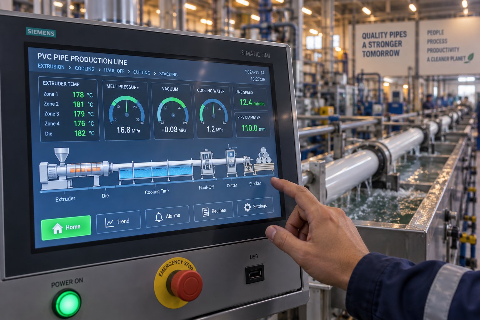
At the output end, ultrasonic wall-thickness gauges continuously scan the pipe circumference during production — non-destructively and in real time. These sensors detect deviations from target wall thickness before a defective section travels meters down the line. Linked back to the central PLC, they can trigger automatic adjustments to haul-off speed or extruder output, creating a closed-loop system that self-corrects without operator intervention.
Between these two endpoints, a centralized PLC control panel orchestrates every unit in the line. Globally recognized platforms — Siemens, B&R, ABB — are preferred over proprietary, closed-box systems because they ensure spare parts availability, local technician familiarity, and straightforward troubleshooting. Open-architecture PLCs also integrate seamlessly with SCADA (Supervisory Control and Data Acquisition) systems, which aggregate process data from every sensor and actuator into a single supervisory dashboard.
Here is a summary of the key automation technologies and their specific production benefits:
- Gravimetric dosing — controls weight-per-meter output precisely, reducing material waste by eliminating over-thick walls caused by volumetric feeding inaccuracies
- Ultrasonic wall-thickness measurement — provides continuous, non-contact dimensional monitoring around the full pipe circumference, catching deviations in real time
- Centralized PLC control — synchronizes extruder speed, haul-off velocity, cutter timing, and temperature zones from a single touchscreen interface, reducing operator error
- SCADA integration — collects and visualizes process data across the entire line, supporting trend analysis, alarm management, and historical traceability for quality audits
- Remote monitoring dashboards — allow production managers and equipment suppliers to view live process data via secure internet connections, enabling faster troubleshooting and management oversight across multiple facilities
- Automated recipe management — stores complete parameter sets (temperature profiles, speed settings, vacuum levels) for each pipe specification, reducing changeover time from hours to minutes and eliminating manual entry errors
- Melt pressure and temperature sensors at the die head — provide early warning of degradation, blockages, or formulation inconsistencies before they manifest as visible defects in the finished pipe
The cumulative effect is measurable. Scrap rates on well-automated lines commonly fall below 2-3%, compared to 5% or higher on manually controlled setups. Labor requirements drop to one or two operators per shift for a fully automated line, versus three or four for semi-automated configurations. And quality documentation — increasingly demanded by municipal water authorities and ISO-certified buyers — is generated automatically rather than reconstructed from handwritten logs.
Investment Planning and Capacity Considerations
Technical specifications determine what a line can produce. Financial planning determines whether producing it makes business sense. Yet most equipment guides stop at the machinery and never address the broader PVC pipe plant setup requirements that define total project cost.
Capital expenditure for a complete production line spans several major categories beyond the equipment itself:
| Cost Category | What It Covers | Planning Considerations |
|---|---|---|
| Equipment (Machinery) | Extruder, die head, vacuum calibration tank, cooling tanks, haul-off, cutter, stacker, optional belling machine | Accounts for the largest portion of CapEx; varies significantly by pipe diameter range, output capacity, and automation level |
| Installation and Commissioning | Mechanical assembly, electrical connections, piping for water and compressed air, system integration, test runs | Clarify whether supplier quotations include installation labor, travel costs, and on-site training; budget 2-4 weeks for commissioning |
| Facility Preparation | Factory building or modifications, foundation work, ventilation, material storage areas, finished goods warehousing | Total linear floor space for a complete line ranges from 20-25 meters (small diameter) to 40-50 meters (large diameter); ceiling height must accommodate extruder hopper and overhead cranes |
| Utilities Infrastructure | Electrical supply (continuous kW load for drive motors and barrel heaters), chilled water circulation system, compressed air for pneumatic cutting and belling units | Verify local power grid stability; calculate chilled water volume per minute based on maximum cooling demand; ensure compressed air pressure meets cutter and actuator requirements |
| Raw Material Working Capital | Initial resin and additive inventory to sustain production during the ramp-up period | Raw materials represent 70-80% of ongoing operating expenditure; secure supplier contracts before commissioning to stabilize pricing |
Staffing requirements scale with automation level and line count. A single fully automated line typically requires one to two operators per shift for monitoring, quality checks, and packaging — plus maintenance technicians available across shifts. Semi-automated lines may require two to four operators per shift. Beyond the production floor, factor in a mixing operator for the compounding station, warehouse personnel, a quality control technician, and at minimum one process engineer who understands the full line. For multi-line plants, a dedicated maintenance team becomes essential to minimize unplanned downtime.
A common misstep among first-time investors is sizing equipment based on optimistic sales projections rather than verified market demand. Running a high-capacity line at 40% utilization is more expensive per kilogram of output than running a smaller, matched line at 80%. Energy costs — which typically represent 10-15% of total operating expenditure — do not scale down linearly when throughput drops, because barrel heaters and cooling systems draw substantial power regardless of output rate. The same logic applies to cooling water circulation, compressed air, and staffing.
Size your production line to run consistently at 75-80% of rated capacity against confirmed market demand — not theoretical maximums. An oversized line operating at half capacity erodes margins faster than a right-sized line running full shifts.
Rather than chasing a single all-encompassing number for PVC pipe production line cost, request itemized quotations from equipment suppliers based on your specific target: pipe diameter range, hourly output, compound type (UPVC vs. CPVC), and desired automation level. Ask for separate line items covering machinery, spare parts packages, installation, training, and warranty terms. Compare proposals not just on sticker price but on total cost of ownership — including energy consumption per kilogram, expected wear part replacement intervals, and after-sales support responsiveness.
Gross profit margins for PVC pipe manufacturing typically fall in the 20-30% range under normal operating conditions, with net margins of 8-12%. Those margins depend heavily on material utilization efficiency, energy management, and production uptime — all areas where the automation technologies discussed above pay for themselves through measurable, compounding gains.
With a clear picture of both the technology stack and the financial framework, the final step is pulling these threads together into a practical decision-making roadmap — one that helps you move from research and planning into confident equipment specification and supplier selection.
Building the Right PVC Pipe Production Line for Your Goals
You have walked through every stage — from resin selection and compound formulation, through mixing, extrusion, calibration, cooling, cutting, and stacking, and into the automation and financial architecture that determines whether the line delivers a return or drains capital. The question now is practical: how do you translate all of that knowledge into decisions that hold up on a factory floor?
The single most important principle to carry forward is this: a PVC pipe production line is an integrated system, not a collection of individual machines. A world-class extruder fed by a mediocre mixer produces mediocre pipe. A precision die head paired with an unstable haul-off produces inconsistent wall thickness. Every unit's performance is constrained — or enabled — by the units upstream and downstream. Planning decisions that treat components in isolation inevitably create bottlenecks, quality gaps, or wasted capacity somewhere in the chain.
Matching Equipment Specifications to Your Target Output
Sounds straightforward, yet this is where many projects go wrong. Buyers fixate on the extruder model or the headline output number and overlook the engineering work that should happen before any equipment is specified. The following checklist prioritizes the decisions in the order they should be made — each step informing the next — whether you are planning a new factory from scratch or upgrading an existing line.
- Define your product scope precisely. Document the exact pipe material (UPVC, CPVC, or PVC-O), diameter range (minimum and maximum), wall thickness classes, applicable standards (ISO, ASTM, DIN, or local equivalents), and target applications (pressure water, drainage, conduit). These parameters dictate every downstream equipment choice. As one industry buying guide emphasizes, even two pipes using similar raw materials can require entirely different extrusion, cooling, and cutting configurations.
- Establish realistic output targets. Calculate required throughput in kg/h and line speed in m/min for your most commonly produced pipe size — not just the theoretical maximum. Plan to operate the line at 75-80% of rated capacity to preserve mechanical longevity and maintain stable melt quality.
- Select the extruder type based on your product and output range. For small-to-medium diameter rigid UPVC pipe, conical twin-screw extruders remain the proven workhorse. For large-diameter pressure pipe or operations requiring formulation flexibility, parallel twin-screw systems offer processing advantages. Single-screw extruders serve only the simplest, lowest-output applications. Match the extruder to the compound, the diameter, and the volume — not to the lowest price.
- Size downstream equipment to match maximum extruder output. Vacuum calibration tank length, total spray cooling capacity, haul-off clamping force, and cutter speed must all accommodate the upper end of your planned production range. Undersized downstream equipment creates immediate bottlenecks that limit the entire line's throughput regardless of extruder capability.
- Determine the automation level appropriate to your operation. Gravimetric dosing, inline wall-thickness measurement, centralized PLC control, and recipe management systems deliver measurable gains in consistency, scrap reduction, and labor efficiency. However, not every plant needs the highest tier of automation on day one. Choose a PLC platform from a globally recognized brand — Siemens, B&R, or ABB — and ensure the system architecture supports future upgrades as your operation scales.
- Verify facility infrastructure before ordering equipment. Confirm that your factory floor offers sufficient linear space (20-50 meters depending on diameter range), stable electrical supply for continuous motor and heater loads, adequate chilled water circulation capacity, and compressed air pressure for pneumatic systems. Infrastructure shortfalls discovered during installation are expensive to resolve under time pressure.
- Specify mixing and compounding equipment with equal rigor. The hot-and-cold mixer set is not an afterthought — it is foundational. Confirm batch capacity aligns with extruder consumption rate, verify that the hot mixer reaches target discharge temperature reliably, and plan dry blend storage with adequate resting time before extrusion.
- Prepare a detailed request for quotation (RFQ). Include every parameter from the steps above: pipe material, diameter range, wall thickness, output targets, applicable standards, automation requirements, voltage specifications, and factory layout dimensions. The more precise the RFQ, the more accurate and comparable the technical proposals you receive from suppliers.
This sequence matters because each decision constrains the next. Skipping ahead — selecting an extruder before defining the product scope, for example — almost guarantees mismatches that surface during commissioning or, worse, during the first production campaign.
Selecting Reliable Component Suppliers
With specifications locked down, the next challenge is sourcing. And here, a critical distinction often gets lost in the procurement process: the difference between evaluating a supplier on initial purchase price versus evaluating them on total value delivered over the equipment's operational life.
Price matters, obviously. But in a PVC pipe manufacturing equipment guide, what deserves emphasis is that the cheapest quotation frequently excludes items that become expensive surprises — installation support, operator training, spare parts packages, calibration tooling, or warranty coverage for high-wear components like screws and barrels. A thorough supplier evaluation should weigh several factors beyond the headline number:
- Technical support capability — Can the supplier's engineering team recommend configurations based on your specific pipe specifications, or do they only offer standard catalog models? Suppliers with process knowledge help you avoid specification errors before they become costly hardware problems.
- Customization options — Does the supplier manufacture or source components tailored to your compound, diameter range, and output targets? Off-the-shelf solutions work for standard applications, but any deviation — higher filler loading, unusual resin grades, atypical diameter ranges — demands tailored engineering.
- Lead times and inventory — How quickly can the supplier deliver replacement parts for wear components? A barrel or screw set that takes three months to deliver means three months of degraded output or complete line downtime.
- After-sales service and remote diagnostics — Does the supplier offer remote troubleshooting via the PLC system? Can they dispatch field service engineers within a reasonable timeframe? Long-term production stability depends on responsive support, not just initial machine quality.
One strategic approach worth considering is the specialist-supplier model — sourcing critical wear components from companies whose entire focus is that specific part, rather than relying exclusively on the turnkey line provider for every replacement. Turnkey suppliers excel at system integration and commissioning, but their replacement parts are not always optimized for your specific application or competitively priced for ongoing maintenance.
Take the conical twin-screw barrel as an example — arguably the single most critical wear component in a PVC pipe extrusion line. When the original barrel reaches end of life after thousands of production hours, sourcing a replacement from a specialist like NANHAIYA — a manufacturer focused specifically on conical twin screw barrels for PVC pipe, profile, board, foam board, and WPC extrusion — can offer advantages in customization precision, material-specific metallurgy, and lead time compared to ordering through the original equipment manufacturer's general parts catalog. This kind of targeted sourcing ensures the replacement barrel is engineered for stable plasticizing performance in your exact application rather than being a generic fit across dozens of machine brands.
The broader lesson: build a supplier network, not just a supplier relationship. Your turnkey provider handles system design and integration. Specialist component manufacturers handle the wear parts and upgrades that keep the line performing at peak over years of continuous operation. Material suppliers handle resin and additive consistency. Together, these relationships form the support ecosystem your production line depends on long after the commissioning engineers leave.
Whether you are setting up your first PVC pipe factory or expanding an existing operation into new diameter ranges, new pipe types, or higher automation tiers, the path forward is the same: define the product, size the system as an integrated whole, specify with precision, and select suppliers who bring process knowledge — not just hardware. A production line built on those foundations does not just manufacture pipe. It manufactures competitive advantage.
Frequently Asked Questions About PVC Pipe Production Lines
1. What are the main stages of a PVC pipe production line?
A PVC pipe production line operates through six core stages executed in sequence: raw material mixing and compounding, extrusion (where the PVC compound is melted and pressurized), vacuum calibration (which locks in the pipe's outer diameter using negative pressure and a sizing sleeve), spray or immersion cooling (to fully solidify the pipe wall), haul-off and cutting (pulling the pipe at controlled speed and sectioning it to length), and finally stacking or bundling for storage. Each stage depends on the one before it — for example, inconsistent mixing leads to uneven melt flow in the extruder, which causes wall thickness variation that no downstream adjustment can fully correct. The entire system must be synchronized through speed, temperature, and pressure controls to produce pipe that meets dimensional and mechanical standards.
2. Why is the conical twin-screw extruder the most common choice for PVC pipe extrusion?
Conical twin-screw extruders dominate rigid PVC pipe production because their tapered screw geometry is uniquely suited to PVC's shear-sensitive processing characteristics. The counter-rotating screws create enclosed C-shaped chambers that convey material forward with low-intensity shear at speeds typically between 30 and 150 rpm, significantly reducing the risk of thermal degradation. The naturally tapering barrel provides built-in compression — the larger feed inlet accepts low-bulk-density dry blend easily, while the narrowing discharge end builds melt pressure without requiring excessive screw speed. This combination delivers stable plasticizing performance critical for pressure-rated pipe where wall thickness uniformity is non-negotiable. Specialist suppliers such as NANHAIYA (nhyscrews.com) manufacture custom and replacement conical twin screw barrels specifically for PVC pipe, profile, and board extrusion, ensuring that when these wear components reach end of life, replacements are engineered for the exact application rather than being generic fits.
3. What causes fish eyes in PVC pipe and how can they be eliminated?
Fish eyes — small, hard circular spots on the pipe surface — are almost always undispersed gels or additive agglomerates that failed to fully fuse during either the mixing or extrusion stage. Common root causes include insufficient hot-mix discharge temperature (leaving calcium carbonate or other fillers poorly bonded to PVC grains), an imbalanced lubricant system that delays gelation inside the extruder, contaminated raw materials introducing foreign particles, and inadequate shear energy during extrusion. Effective elimination requires working backward through the process: first inspect the dry blend for lumps, uniform color, and correct discharge temperature before adjusting extruder parameters. Verifying filler moisture content and particle size, adjusting the internal-to-external lubricant ratio, and checking the screen pack for blockages are targeted corrective actions that address root causes rather than masking symptoms.
4. What is the difference between UPVC, CPVC, and PVC-O pipe production?
All three pipe types share a polyvinyl chloride base but diverge significantly in processing requirements. UPVC (unplasticized PVC) is the industry standard, processed at barrel temperatures of 160-200 degrees Celsius on standard twin-screw extrusion lines for drainage, water supply, and conduit applications. CPVC (chlorinated PVC) has elevated chlorine content that raises its heat deflection temperature, allowing service up to approximately 93 degrees Celsius — but it requires barrel temperatures 20-40 degrees Celsius higher than UPVC, higher-torque extruders, specialized stabilizer systems, and more precise thermal control due to a narrower processing window. PVC-O (molecularly oriented PVC) begins as standard UPVC extrusion but adds a molecular orientation stage — either inline or offline — that stretches and aligns PVC molecular chains, dramatically improving impact resistance and pressure rating at reduced wall thickness. PVC-O requires dedicated orientation machinery and typically involves licensing agreements, representing a significant additional capital investment beyond a standard line.
5. How much floor space and infrastructure does a PVC pipe production line require?
A complete PVC pipe production line requires 20 to 25 meters of linear floor space for small-diameter configurations and 40 to 50 meters for large-diameter setups, with ceiling height sufficient to accommodate the extruder hopper and overhead crane access. Beyond physical space, infrastructure requirements include a stable electrical supply capable of sustaining continuous kilowatt loads from drive motors and barrel heaters, a chilled water circulation system sized to the maximum cooling demand of the vacuum calibration and spray tanks, and compressed air at pressures adequate for pneumatic cutting and belling units. Facility preparation — including foundations, ventilation, raw material storage, and finished goods warehousing — represents a distinct cost category that should be budgeted separately from equipment. Verifying all infrastructure before ordering machinery prevents expensive delays during installation and commissioning.
Written by
Nanhaiya Technical Team
Zhoushan Nanhaiya Plastic Machinery Co., Ltd.
The Nanhaiya technical team supports screw and barrel manufacturing projects through application review, technical communication, custom manufacturing coordination, and production and quality control.
Discuss Your Application
Related Articles
More insights on screw barrel technology and plastics processing.
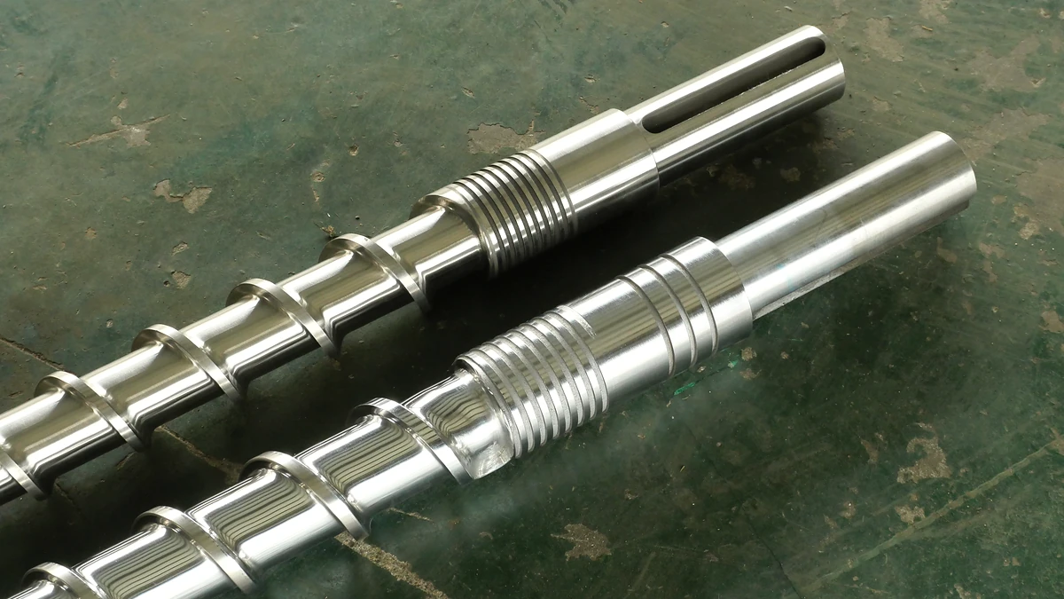
How The Wrong Extruder Screw Barrel For PP Ruins Your Melt
Oct 27, 2026
Learn why PP extrusion needs a purpose-built extruder screw barrel for PP — covering geometry, metallurgy, mixing elements, temperature profiles, and troubleshooting.
Read Article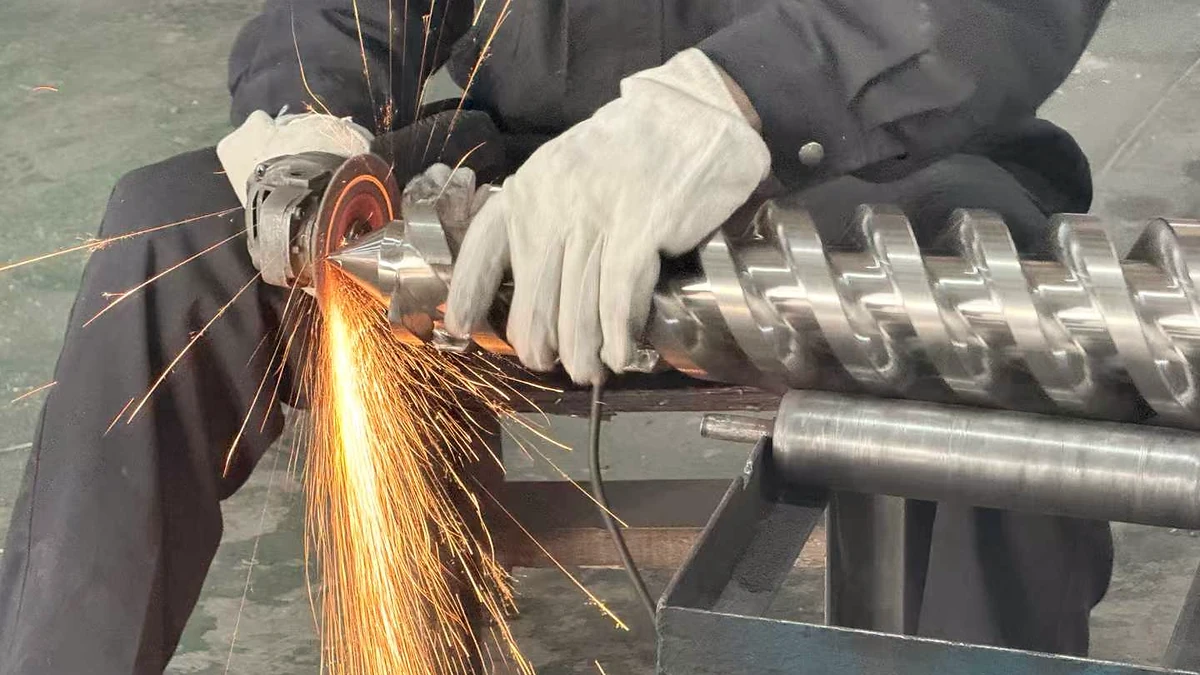
Plastic Extruder Screw Barrel Service: Match The Fix To The Wear
Oct 27, 2026
Learn how plastic extruder screw barrel service works — from zone-by-zone wear diagnosis and measurement methods to repair techniques, material matching, and maintenance scheduling.
Read Article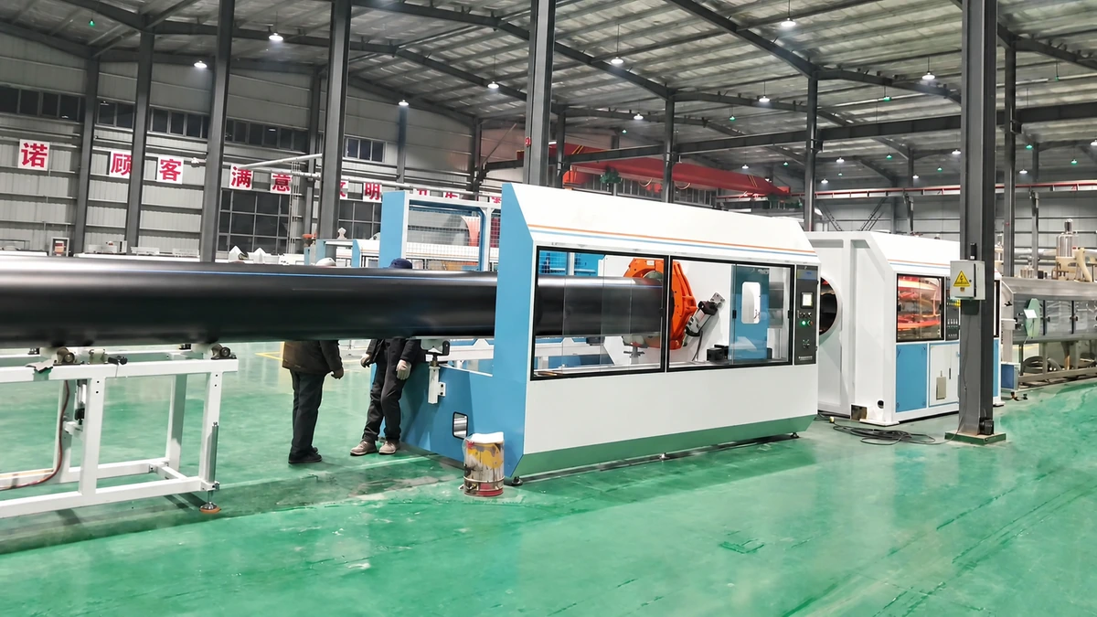
PE Pipe Extrusion Line Decoded: From Pellet to Perfect Pipe
Oct 27, 2026
Learn how a PE pipe extrusion line works — components, process steps, screw-barrel selection, vacuum calibration, automation, and a buyer's guide for smart purchasing.
Read ArticleLooking for something else?
Search by material, symptom or product and jump straight to the relevant page.
These are navigation suggestions based on keyword matching — not a quotation, not a delivery commitment, and not a substitute for engineering review. Final specification is confirmed by our engineers against your drawings and processed material.
Need help with screw barrel selection?
Share your machine model, processed material and application. Our team can help with pricing and technical support.