

What a PVC Pipe Manufacturing Machine Does and Why It Matters
Imagine a system that takes powdery PVC resin compound at one end and delivers precisely dimensioned, ready-to-ship pipes at the other — all in a single, continuous operation. That is exactly what a PVC pipe manufacturing machine does, and understanding its full scope is the first step toward making smart investment and operational decisions.
What Exactly Is a PVC Pipe Manufacturing Machine
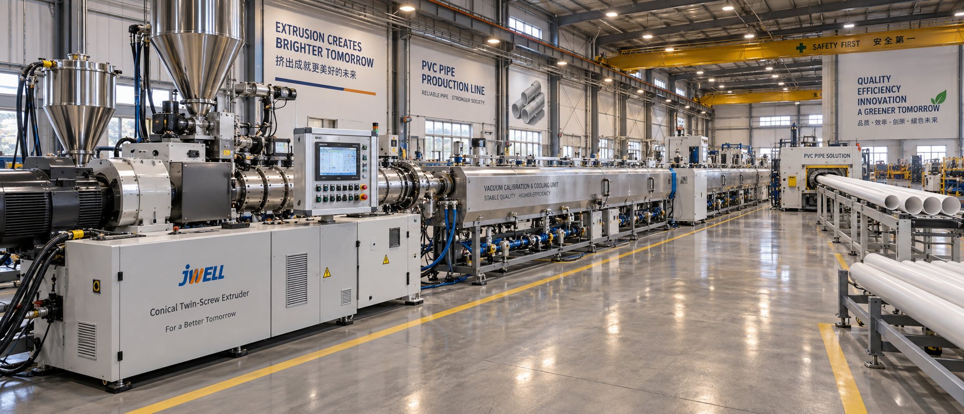
A PVC pipe manufacturing machine is an integrated extrusion-based production system that converts dry PVC resin compound into finished pipes through a continuous sequence of plasticizing, shaping, vacuum sizing, cooling, haul-off traction, cutting, and socketing — executed by multiple synchronized units operating as a single coordinated line.
The term "machine" can be misleading. In practice, a PVC pipe production line is not one device but a chain of specialized equipment working in tight synchronization. It typically stretches 30 to 50 meters across a factory floor and includes a high-speed mixer, a conical twin-screw extruder, a die head, vacuum calibration tanks, spray cooling baths, a haul-off unit, a cutting station, and often a belling machine and stacker. Each unit handles a distinct phase of the process, yet they all depend on one another for consistent output. A mismatched haul-off speed or an improperly calibrated vacuum tank can ripple upstream and downstream, causing dimensional defects in seconds.
This system-level perspective matters because buyers who evaluate only the extruder — or only the price tag — risk overlooking the auxiliary equipment that ultimately determines pipe quality and production efficiency. Every component in the pipe production line plays a role, and the weakest link sets the ceiling for overall performance.
Why PVC Pipe Production Matters Across Industries
PVC pipes are everywhere — beneath city streets, across farmland, inside walls, and around electrical conduits. Their dominance stems from a practical combination of corrosion resistance, affordability, lightweight handling, and a service life that commonly reaches 25 to 50 years depending on application conditions. Unlike metal alternatives, they don't rust, scale, or require protective coatings, which translates to lower lifecycle costs for end users.
The numbers reflect this demand. The global plastic pipes market reached USD 85.48 billion in 2025 and is projected to grow to USD 137.36 billion by 2034 at a CAGR of 5.4%. Building and construction holds the largest application share, while agriculture is expected to grow even faster at 6.6% CAGR. Asia Pacific alone accounted for 43.72% of global demand, driven by massive water infrastructure investments and urbanization. The PVC segment specifically is forecast to grow at roughly 5.2% CAGR, fueled by continued use in plumbing, drainage, and irrigation systems worldwide.
What drives this steady expansion? Aging pipeline networks in developed economies need replacement. Developing regions are building new water supply and sanitation systems at scale. Agricultural irrigation is expanding. And regulatory standards increasingly favor durable, corrosion-resistant piping over traditional materials. Each of these trends feeds directly into demand for reliable, high-throughput PVC pipe extrusion capacity.
For manufacturers, this means the equipment behind every meter of pipe — the extruder, the die, the cooling system, the controls — must deliver consistent quality at competitive cost. The sections ahead break down exactly how that happens: the types of pipes these lines produce, the critical components involved, the step-by-step manufacturing process, screw and barrel design principles, machine selection criteria, defect troubleshooting, and maintenance practices that keep production running smoothly.
Types of PVC Pipes and How Machine Configurations Differ
Not all PVC pipes are created equal — and the machines that produce them aren't identical either. A plastic pipe production line built for thin-walled electrical conduit operates very differently from one engineered to extrude thick-walled pressure pipes for municipal water supply. The pipe's end-use application dictates everything from die head geometry to cooling strategy, and understanding these differences is essential before specifying equipment.
UPVC Pressure Pipes vs Drainage and Conduit Pipes
UPVC pressure pipes — used in potable water supply, irrigation mains, and industrial fluid transport — must meet strict dimensional tolerances and burst-pressure ratings. The die heads for these pipes use heavier mandrels and tighter land lengths to produce uniform, thick walls capable of handling sustained internal pressure. Vacuum calibration tanks run at higher vacuum levels to lock in precise outer diameters, and spray cooling sections are longer because thicker walls need more time to solidify without trapping residual stress.
Drainage and soil-waste-rainwater (SWR) pipes, on the other hand, are non-pressure products. They have thinner walls relative to their diameter, so a pvc pipe making machine configured for drainage work typically runs at faster haul-off speeds and shorter cooling zones. Die heads are designed with wider annular gaps to accommodate larger diameters — often 110 mm to 315 mm — without the heavy wall buildup that pressure pipe demands. Electrical conduit pipes push this even further: their small diameters (typically 16 mm to 50 mm) and thin walls allow very high extrusion speeds, sometimes requiring multi-cavity dies to run two or more pipes simultaneously for better throughput.
CPVC and Specialty Pipe Configurations
CPVC pipes handle both hot and cold water, withstanding temperatures up to 93 degrees Celsius compared to roughly 60 degrees Celsius for standard UPVC. This higher thermal capability comes from additional chlorination of the PVC resin, but it also means the processing window is narrower and more demanding on equipment.
What changes on the machine side? Processing temperatures climb significantly — barrel zone setpoints for CPVC typically run 10 to 20 degrees Celsius higher than for UPVC. This increased heat, combined with the more aggressive nature of chlorinated resin, accelerates wear and corrosion inside the barrel. Manufacturers processing CPVC regularly need barrels with enhanced corrosion-resistant linings and screws built from alloys that resist both abrasion and chemical attack. Die heads also require corrosion-resistant steel, and temperature control across all zones becomes more critical because CPVC degrades faster than standard PVC if overheated.
Casing pipes for bore wells represent another specialty segment. These large-diameter, thick-walled pipes (often 100 mm to 250 mm) demand high extruder torque and extended cooling lines. A plastic pipe making machine sized for casing pipe production typically features larger screw diameters and more powerful drive motors to handle the high output rates these heavy pipes require.
Matching Pipe Application to Machine Specification
You'll notice a recurring theme here: the pipe's intended application drives every major machine parameter. Diameter range, wall thickness, material type, and pressure rating all influence screw design, die selection, cooling capacity, and haul-off configuration. The table below maps common pipe types against the key equipment variables that shift with each application.
| Pipe Type | Typical Diameter Range | Die Type | Screw Design Consideration | Cooling Method |
|---|---|---|---|---|
| UPVC Pressure Pipe | 20 mm - 630 mm | Heavy mandrel, tight tolerance die | Standard conical twin screw; moderate compression ratio for uniform melt | Extended vacuum sizing + multi-stage spray cooling |
| Drainage / SWR Pipe | 75 mm - 315 mm | Wide annular gap die for thin walls | Standard conical twin screw; higher throughput settings | Shorter spray cooling; lower vacuum pressure |
| Electrical Conduit Pipe | 16 mm - 50 mm | Multi-cavity die (2 or 4 pipes) | Smaller screw diameter; high-speed output focus | Immersion or short spray bath |
| CPVC Hot/Cold Water Pipe | 15 mm - 80 mm | Corrosion-resistant die steel | Corrosion-resistant barrel lining; tighter temperature control | Controlled spray cooling to manage thermal stress |
| Bore Well Casing Pipe | 100 mm - 250 mm | Heavy-duty single-pipe die | Larger screw diameter; high torque drive for thick walls | Extended spray cooling with longer tank sections |
This comparison highlights a practical reality: there is no single "universal" machine setup. Buyers evaluating a plastic pipe production line need to start with a clear definition of their target pipe portfolio — diameters, wall classes, materials, and annual output targets — before engaging any equipment supplier. A line optimized for 20 mm conduit won't efficiently produce 400 mm pressure pipe, and vice versa. Getting this match right from the outset prevents costly retrofits and production bottlenecks down the road.
Pipe type and machine configuration are only half the picture, though. Each unit in the line — from the mixer feeding raw compound to the stacker collecting finished pipes — contributes specific capabilities and constraints that shape overall production performance.
Key Components of a Complete PVC Pipe Production Line
Every meter of finished PVC pipe passes through a tightly choreographed sequence of specialized stations — each one doing a single job exceptionally well. Strip any one unit out of the line, and the entire process stalls. Understanding what each piece of plastic pipe equipment does, what specifications matter most, and what separates a reliable unit from a problematic one gives buyers a decisive edge when evaluating quotations and comparing suppliers.
Here is the full sequence of PVC pipe production line components from raw material intake to finished pipe stacking:
- High-speed mixer and cooling mixer — blends PVC resin with stabilizers, lubricants, fillers, and pigments at high RPM (typically 800-1,200 RPM) to produce a homogeneous dry compound, then transfers the hot blend to a cooling mixer that brings it below 40-50 degrees Celsius for safe storage and feeding.
- Automatic feeder / hopper loader — transports the cooled dry blend from storage into the extruder hopper using vacuum or screw conveying, ensuring consistent, uninterrupted material supply without manual handling.
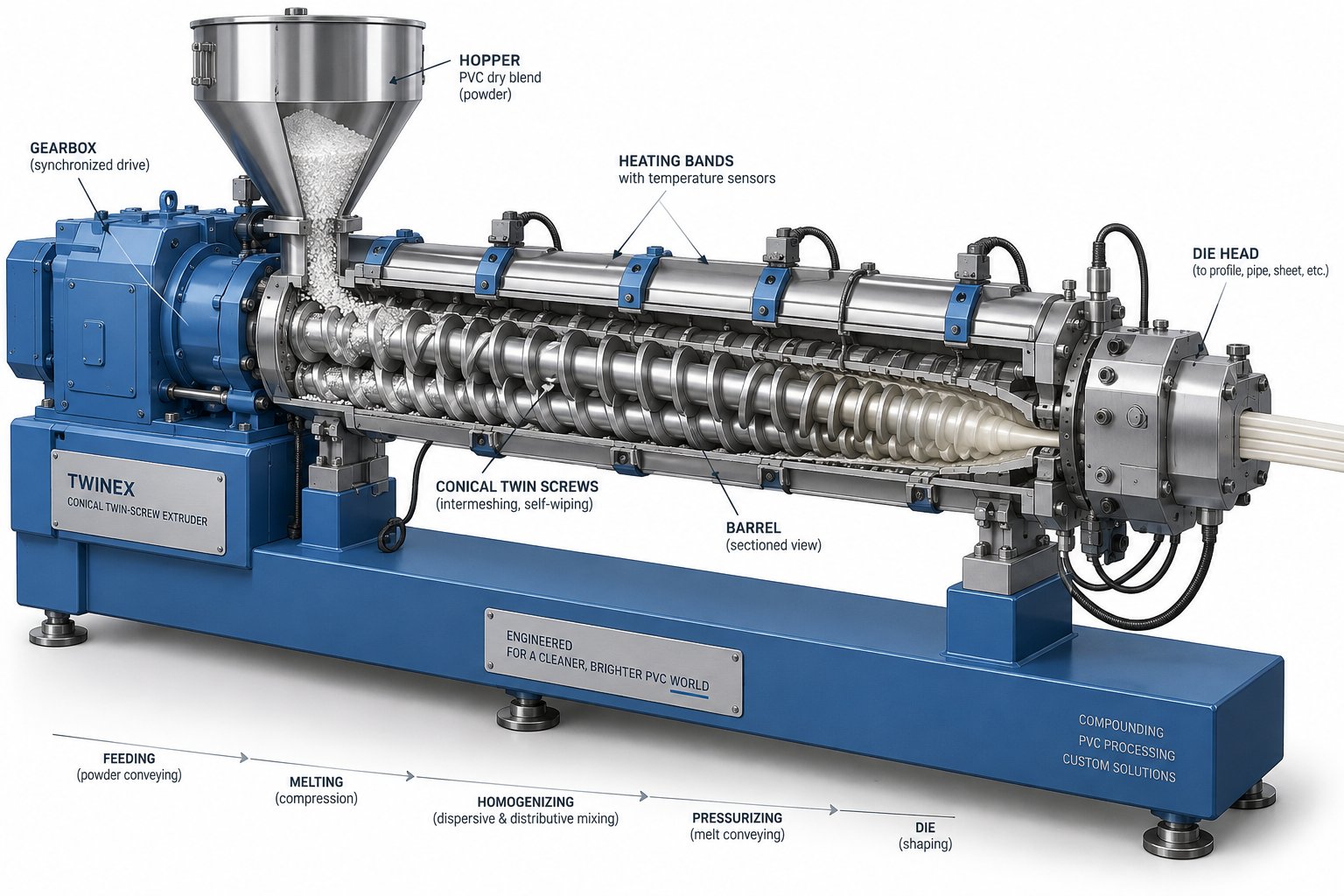
- Conical twin-screw extruder — the heart of the line, where dry blend is plasticized into a uniform, homogeneous melt through controlled heat and mechanical shear, then pushed forward under pressure toward the die.
- Extrusion die head and mandrel — shapes the molten PVC into a hollow tube with precise wall thickness and diameter; the mandrel forms the inner bore while the die body defines the outer surface.
- Vacuum calibration / sizing tank — applies external vacuum pressure to pull the still-soft extrudate against a precision sizing sleeve, locking in the pipe's outer diameter to tight tolerances while beginning initial cooling.
- Spray cooling tank(s) — continues solidifying the pipe wall through multi-stage water spray sections; longer tanks are used for thicker-walled pipes that require more cooling time.
- Caterpillar or belt haul-off unit — grips the solidified pipe and pulls it at a precisely controlled speed that must stay synchronized with the extruder output to maintain consistent wall thickness.
- Planetary or chip-free cutting machine — cuts pipe to specified lengths on-the-fly without stopping the line, producing clean, burr-free ends.
- Belling / socketing machine — heats one end of the cut pipe and expands it into a socket shape for push-fit jointing, if required by the pipe specification.
- Automatic stacker — collects, organizes, and stacks finished pipes for storage or shipment, reducing manual labor and handling damage.
From Mixer to Extruder — Feed Preparation and Plasticizing
The high-speed mixer is where production quality actually begins. When you evaluate a mixer, look at motor power, mixing blade design, and the quality of temperature sensors inside the mixing chamber — these determine whether the dry blend reaches proper gel temperature (typically 110-120 degrees Celsius for rigid PVC) consistently from batch to batch. An undersized or poorly instrumented mixer produces uneven compound, and that inconsistency carries all the way through to the finished pipe.
The cooling mixer works in tandem, preventing the hot blend from clumping or pre-degrading during storage. Stainless steel construction and efficient water-jacket cooling are quality indicators worth verifying.
At the extruder, the specifications that matter most include screw diameter (which directly determines throughput capacity), motor power, gearbox torque rating, and the number of independent barrel heating zones — typically four to five on production-grade machines. A PVC machine built around a robust conical twin-screw design delivers the high feed-zone torque needed to intake low-bulk-density dry blend while building pressure progressively through the barrel for thorough plasticizing. Gearbox quality is a silent but critical factor: a weak gearbox limits the screw's usable torque range and shortens machine life under sustained production loads.
Die Head and Vacuum Calibration Tank Explained
The die head is where molten PVC takes its shape. Imagine forcing a viscous melt through a precisely machined annular gap — the outer ring of the die defines the pipe's external diameter while the central mandrel creates the hollow core. Die heads for PVC pipe extrusion line equipment are typically spiral-mandrel or basket designs that distribute melt flow evenly around the full circumference of the pipe. Uneven flow produces wall thickness variation, so the machining precision and flow-channel design of the die head directly impact pipe quality.
Buyers should check whether the die head offers adjustable centering bolts — these allow operators to fine-tune the mandrel position relative to the die body, correcting minor eccentricity during production without a full shutdown.
The vacuum calibration tank sits immediately after the die. Its job is deceptively simple: hold the soft pipe against a sizing sleeve using vacuum pressure — typically 0.02 to 0.06 MPa — while circulating chilled water to begin solidification. Tank length, vacuum pump capacity, water temperature control, and the precision of the sizing sleeve itself are the key specifications. A well-built calibration tank includes easy-access adjustment mechanisms for vacuum level and water flow, plus quick-change sizing sleeves for different pipe diameters.
Haul-Off Cutting Socketing and Stacking Units
Downstream of the cooling tanks, the haul-off unit takes over. Caterpillar-type haul-offs with rubber-padded belts or tracks grip the pipe firmly without marking the surface and pull at a speed set by the PLC. The critical requirement here is speed stability — even small fluctuations cause measurable wall thickness variation. Servo-driven or high-quality inverter-driven haul-offs with encoder feedback deliver the consistency needed for pressure-rated pipes.
The cutting machine operates on-the-fly, tracking the moving pipe and making clean cuts without stopping the line. Planetary saws are the standard for rigid PVC, rotating around the pipe to produce chip-free, square ends. Buyers should verify the cutter's diameter range, cut accuracy (typically plus or minus 1-2 mm), and dust collection provisions.
Belling machines and automatic stackers round out the line. Belling quality depends on oven temperature uniformity and mold precision, while stackers should be evaluated for pipe diameter range compatibility and cycle speed relative to the line's output rate.
Why Control System Quality Matters
Tying all these units together is the electrical and control architecture. A PVC pipe production line relies on PLCs to coordinate temperature zones, screw speed, haul-off traction, vacuum levels, and cutting sequences in real time. As detailed in a comprehensive overview from PLC Programming IO, the PLC manages multiple PID loops simultaneously — one per barrel temperature zone, one for screw speed via VFD, and coordinated ratio links between the extruder and all downstream stations.
This is exactly why reputable component brands matter. PLCs from Siemens, inverters from ABB or Schneider, temperature controllers from OMRON — these aren't luxury upgrades. They deliver more stable control loops, better fault diagnostics, and critically, worldwide after-sales support and spare parts availability. A factory running a no-name PLC may save a few hundred dollars at purchase but risks extended downtime if a controller fails and replacements aren't readily available. When evaluating any pvc machine supplier's quotation, ask specifically which brands are used for PLCs, VFDs, contactors, and temperature controllers — and whether those components can be sourced locally for fast replacement.
With every component in the line accounted for — from mixer blade to stacker arm — the next logical question is how all these units work together in real time: what actually happens to PVC resin as it moves through each stage, and where the critical process parameters determine whether a good pipe or a defective one comes out the other end.
The PVC Pipe Manufacturing Process Step by Step
Knowing what each station on the line does is one thing. Understanding what actually happens to the material — molecule by molecule, meter by meter — as it travels from powder hopper to finished pipe stack reveals where quality is won or lost. The PVC pipe manufacturing process step by step is a carefully controlled chain of thermal, mechanical, and dimensional transformations, and every stage depends on the one before it.
Raw Material Blending and Dry Mix Preparation
Production starts not at the extruder but at the mixer. PVC resin on its own is a fine, low-bulk-density powder that cannot be extruded into anything useful without additives. In a high-speed mixer, the resin is combined with heat stabilizers (which prevent thermal degradation during processing), internal and external lubricants (which control melt flow and prevent sticking to metal surfaces), calcium carbonate or other fillers (which reduce cost and can improve stiffness), and pigments for color.
The mixer spins at 800 to 1,200 RPM, generating frictional heat that raises the batch temperature to around 110-120 degrees Celsius. At this point, the resin particles absorb the liquid additives and swell slightly — a stage called gelation or dry-blend formation. The hot compound is then dropped into a cooling mixer, which brings the temperature below 40-50 degrees Celsius to prevent premature degradation or clumping during storage. Sounds straightforward? It is — but inconsistency here, whether from inaccurate weighing, insufficient mixing time, or poor temperature control, creates compound variations that no downstream adjustment can fully correct.
The cooled dry blend is transferred via automatic feeder into the extruder hopper. Consistent volumetric or gravimetric feeding ensures the screw receives a steady, uniform supply. Starve-feeding or surge-feeding introduces pressure fluctuations inside the barrel that translate directly into wall thickness variation in the finished pipe.
Extrusion Plasticizing and Die Forming
This is where the real transformation happens. Inside the conical twin-screw extruder — the core of any PVC pipe machine — the dry blend undergoes three overlapping processes: conveying, melting, and pressure building. The wide feed end of the conical screws pulls in the low-density powder with high torque. As the material advances toward the narrower discharge end, the decreasing channel volume compresses the compound while barrel heaters and inter-particle shear friction raise its temperature into the 170-190 degrees Celsius processing window for rigid PVC.
The goal is melt homogeneity — a state where every cubic centimeter of the material emerging from the screw tips has identical temperature, viscosity, and degree of gelation. Why does this matter so much?
Upstream plasticizing quality determines final pipe dimensional accuracy. If the melt leaving the extruder contains even minor temperature gradients or partially ungelated particles, no amount of downstream calibration, cooling adjustment, or haul-off tuning can produce a consistently round, dimensionally stable pipe.
The homogeneous melt exits the barrel and enters the die head under pressure, typically 15 to 30 MPa at the screw tips. Inside the die, a spiral-mandrel or basket-type flow distributor channels the melt around a central mandrel, spreading it into a uniform annular shape. The melt exits the die lip as a soft, hollow tube — already recognizable as a pipe, but still too hot and pliable to hold its dimensions without external support.
Temperature uniformity across the die is critical. Hot spots cause localized thinning because the less-viscous melt in that zone flows faster, while cold spots produce thicker sections. Operators use individual die-zone heaters and adjustable centering bolts to balance flow distribution, but the foundation of a good extrudate is always the quality of the melt that the screw delivers to the die in the first place.
Sizing Cooling Cutting and Finishing
The soft extrudate passes directly into the vacuum calibration tank — and this is where the pipe's outer diameter gets locked in. A precision-machined sizing sleeve, matched to the target pipe OD, sits at the tank entrance. Vacuum pressure — typically 0.02 to 0.06 MPa — pulls the still-pliable pipe wall outward against the sleeve while chilled water begins solidifying the outer skin. Think of it as a mold that the pipe draws itself into under suction.
The vacuum level is the primary control variable here. Too little vacuum, and the pipe undersizes — it doesn't fully contact the sleeve and comes out smaller than specification. Too much vacuum, and the pipe can collapse or develop surface drag marks. Operators fine-tune vacuum pressure alongside water temperature and flow rate to hold OD within tolerances that are often as tight as plus or minus 0.1 mm for pressure-rated pipes.
After initial sizing, the pipe enters one or more spray cooling tanks where water jets continue extracting heat from the pipe wall. This stage matters more than it might seem. Cooling rate directly affects residual stress locked into the finished pipe. Cool too fast — especially on thick-walled pipes — and the outer surface solidifies and contracts while the inner core is still hot and expanded. The result is built-in tensile stress on the outside and compressive stress on the inside, which can cause warping, reduced impact strength, or premature failure under pressure. Multi-stage cooling with progressively warmer water in later tanks helps manage this thermal gradient.
Downstream of the cooling tanks, the haul-off unit takes control of the pipe's linear speed. This is the critical synchronization point in the entire pvc pipe extrusion process. If the haul-off pulls faster than the extruder delivers material, the pipe wall stretches thinner. Pull too slowly, and material backs up, thickening the wall and potentially causing surging. The relationship is direct and immediate — a 2-3% speed mismatch can produce measurable wall thickness deviation. Servo-driven haul-offs with encoder feedback maintain the kind of speed stability that pressure pipe production demands.
The planetary cutting machine tracks the moving pipe and executes clean, chip-free cuts at preset lengths without stopping the line. After cutting, pipes destined for push-fit jointing move to a belling machine, where one end is heated in an oven, then expanded over a forming mandrel to create a socket. Finally, an automatic stacker collects and arranges the finished pipes for storage or shipment.
Every stage in this sequence is a potential quality gate — and the tolerances get tighter as the pipe moves downstream. Yet the single biggest determinant of success isn't any one calibration setting or cooling parameter. It is the consistency of the melt that exits the extruder, which brings a sharper focus to the component responsible for generating that melt: the screw and barrel system itself.
Screw and Barrel Design That Drives PVC Melt Quality
The melt that exits the extruder determines everything downstream — dimensional accuracy, surface finish, mechanical strength, and even how long the die head stays clean between maintenance stops. And the component responsible for generating that melt? The screw and barrel system. No other single element in a PVC pipe manufacturing machine has a greater influence on output quality, production uptime, and energy consumption. Getting pvc extruder screw and barrel design right is the difference between a line that runs profitably for years and one that battles defects, waste, and premature wear from day one.
Why Conical Twin Screw Design Dominates Rigid PVC Extrusion
Rigid PVC presents a processing challenge that most polymers don't. The dry blend entering the extruder is a low-bulk-density powder — not dense pellets — and PVC is thermally sensitive, releasing corrosive hydrochloric acid (HCl) if overheated. The material needs high intake torque to pull in that fluffy powder, progressive compression to densify and plasticize it, and carefully controlled shear to reach full gelation without degradation. Conical twin-screw extruders handle all three demands through a single elegant geometry.
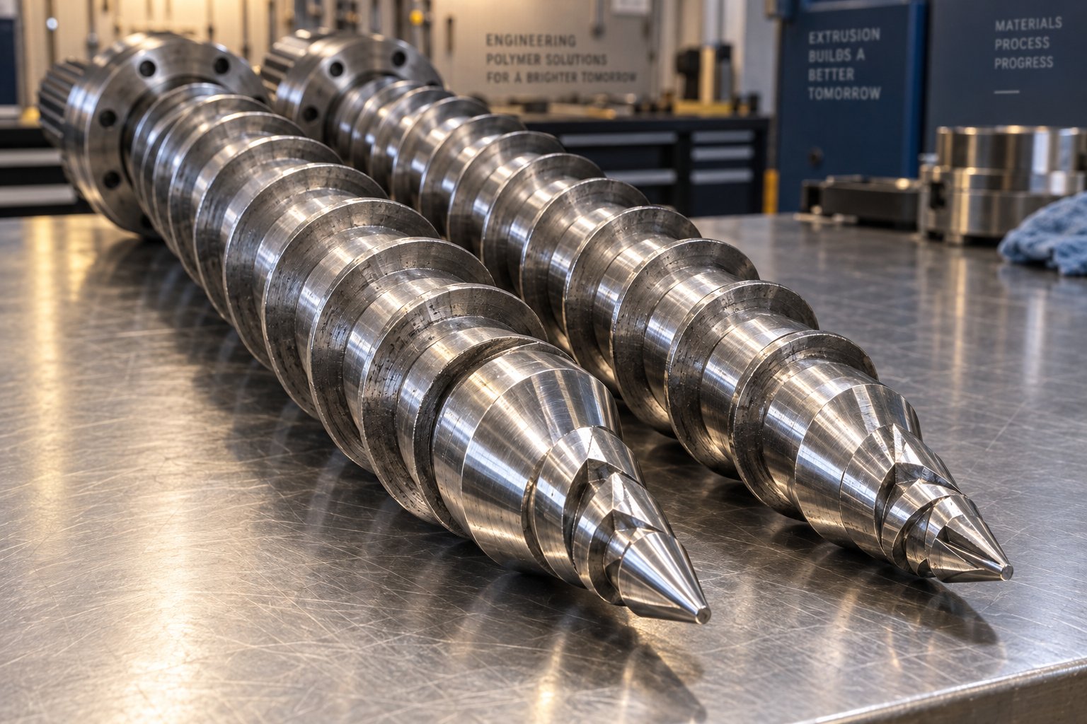
Picture two intermeshing screws that are wide at the feed end and taper toward the discharge. That large-diameter feed zone provides substantial torque for pulling in low-density dry blend — something parallel screws of the same output class struggle to match without longer barrels. As the screws narrow, the channel volume decreases, naturally compressing the material and building the pressure needed for thorough plasticizing. The conical layout also keeps the gearbox simpler and more compact than parallel designs of equivalent torque, reducing both machine cost and maintenance complexity.
The result is a screw geometry purpose-built for rigid PVC: high intake capacity at the rear, progressive compression through the middle, and controlled pressure at the front — all within a relatively short overall length that limits the material's exposure to heat and reduces the risk of thermal degradation.
Compression Ratio L/D Ratio and Screw Geometry Explained
Three parameters define how a conical twin screw barrel for PVC performs: compression ratio, L/D ratio, and flight geometry. Each one directly shapes melt quality, throughput, and wear life.
Compression ratio describes how much the channel volume decreases from the feed end to the discharge end. For rigid PVC, this ratio typically falls between 1.5:1 and 2.5:1 — significantly lower than the 3:1 to 4:1 range common in polyolefin processing. Why the restraint? PVC's narrow thermal window means excessive compression generates too much shear heat, pushing the melt toward degradation. A moderate compression ratio avoids localized overheating while still delivering the pressure needed for complete gelation and homogeneous melt output.
L/D ratio — the flighted screw length divided by its outside diameter — governs residence time and mixing thoroughness. Industry trends have pushed L/D ratios steadily upward over the decades. As polymer engineer Shayan Moin of UniSol notes, screws ran about 20 L/D thirty years ago, moved to 30 L/D fifteen years ago, and today many run 40 L/D. Longer screws provide more gradual heating and mixing, improving melt uniformity — but they also increase energy consumption, machine footprint, and capital cost. Conical screws are inherently limited in length compared to parallel designs, so most conical twin-screw extruders for PVC pipe operate in the 22 to 26 L/D range, relying on their tapered geometry to compensate with higher compression efficiency per unit length.
Screw flight geometry — the shape, pitch, and number of flights — controls how material moves through each processing zone. Well-designed flights transition smoothly between conveying, compression, and metering sections without abrupt channel depth changes. Abrupt transitions create dead spots where material stagnates, overheats, and degrades — a problem that manifests as black specks or burn marks in finished pipe. Advanced screw designs use continuous-change geometry with virtually no free cuts between zones, ensuring material flows directly from one channel to the next without hang-up points that accelerate both wear and polymer decomposition.
| Parameter | Small Machine Class (e.g., SJSZ-51/105) | Mid-Range Machine Class (e.g., SJSZ-65/132) | Large Machine Class (e.g., SJSZ-80/156 or 92/188) |
|---|---|---|---|
| Screw Diameter (small end / large end) | 51 mm / 105 mm | 65 mm / 132 mm | 80 mm / 156 mm or 92 mm / 188 mm |
| Typical L/D Ratio | 22 - 24 | 22 - 25 | 24 - 26 |
| Compression Ratio (Rigid PVC) | 1.8:1 - 2.2:1 | 1.8:1 - 2.3:1 | 2.0:1 - 2.5:1 |
| Typical Output (Rigid PVC Pipe) | 80 - 180 kg/hr | 180 - 400 kg/hr | 400 - 900+ kg/hr |
| Bimetallic Treatment Options | Standard nitrided or bimetallic lining available | Bimetallic barrel lining recommended; tungsten carbide screw overlay available | Bimetallic barrel and screw treatment strongly recommended for high-filler or CPVC formulations |
Barrel Wear Protection and When to Choose Bimetallic Treatment
PVC is hard on barrels and screws in two distinct ways. The calcium carbonate and titanium dioxide fillers commonly used in rigid PVC formulations are abrasive — they physically grind away at screw flight surfaces and barrel bore walls over thousands of operating hours. Simultaneously, the HCl gas released during processing is chemically corrosive, attacking metal surfaces from the inside. This double assault means PVC extruders generally need screw replacement every one to four years, depending on formulation severity and operating practices.
You'll notice wear before you see it. The early symptoms are subtle: reduced throughput at the same screw speed, increased reliance on barrel heaters (because the worn screw generates less shear heat), rising waste rates, and longer changeover times when switching pipe dimensions. In severe cases, waste rates climb from a normal 1.5% to as high as 10%, and startup times for new pipe sizes can double or quadruple.
This is where bimetallic screw barrel PVC extrusion solutions become essential rather than optional. Bimetallic barrels feature a centrifugally cast inner lining of wear- and corrosion-resistant alloy — typically iron-boron or nickel-based alloys — bonded to a standard steel outer shell. For screws, hard-facing with tungsten carbide or stellite on the flight lands provides a wear surface that far outlasts standard nitrided steel. The upfront cost is higher, but the payback comes through extended service intervals, more consistent plasticizing, and lower waste rates over the barrel's lifetime.
When is bimetallic treatment worth the investment? If you're processing formulations with high filler loading — 50 PPH calcium carbonate or above — or running CPVC with its more aggressive chemical profile, bimetallic components pay for themselves quickly. The same applies to any production line running two or three shifts continuously, where the cumulative hours accelerate wear significantly.
For manufacturers sourcing custom or replacement conical twin screw barrels, working with a specialist supplier who understands PVC processing requirements makes a measurable difference. NANHAIYA, for example, engineers conical twin screw barrels specifically for PVC pipe, profile, board, foam board, and WPC extrusion lines — offering bimetallic barrel options and precise screw geometry tailored to the formulation and output demands of each application. This kind of application-specific expertise matters because, as the reference data shows, an optimized screw design can reduce wear by up to 60% compared to generic replacements, while simultaneously improving melt homogeneity and reducing additive consumption.
The practical takeaway is straightforward: the screw and barrel are consumable components, not permanent fixtures. Monitoring wear proactively — measuring screw flight diameters and barrel bore dimensions at regular intervals — and replacing with properly engineered components before quality deteriorates is one of the highest-return maintenance investments any PVC pipe producer can make. But choosing the right screw and barrel is only one dimension of a broader decision framework. The machine itself — its size, motor power, automation level, and auxiliary equipment — must align with your specific production goals, factory layout, and budget realities.
How to Select the Right PVC Pipe Manufacturing Machine
Screw geometry and barrel metallurgy are critical, but they exist within a larger decision framework. Choosing the right PVC pipe manufacturing machine means matching dozens of interdependent variables — pipe specifications, throughput targets, available floor space, electrical infrastructure, and budget — into a coherent equipment package that performs profitably from day one. Get one variable wrong, and you either overspend on capacity you never use or bottleneck production within months of startup.
So where do you begin? Start with the pipe, not the machine.
Defining Your Pipe Specifications and Output Targets
Every equipment decision flows from two foundational questions: what pipes will you produce, and how many kilograms per hour do you need? The target pipe diameter range determines die head selection, calibration tank size, and haul-off capacity. Wall thickness requirements — especially for pressure-rated pipes conforming to standards like ISO 1452 or ASTM D1785 — dictate cooling line length and vacuum calibration precision. And the pipe application itself, whether pressure water supply, non-pressure drainage, or electrical conduit, shapes nearly every downstream parameter, as the earlier comparison table illustrated.
Output capacity deserves careful, realistic planning. A plastic water pipe making machine rated at 300 kg/hr sounds impressive on paper, but that figure assumes optimal conditions — consistent feed, proper melt temperature, and continuous operation. Real-world throughput typically runs 15-25% below nameplate rating once you account for startups, changeovers, and minor stoppages. Size your line for the output you actually need, plus a reasonable growth margin, rather than buying the largest extruder available and running it at half capacity. Under-loaded extruders waste energy and can actually produce poorer melt quality because the screw operates outside its designed compression and shear range.
Matching Screw Diameter and Motor Power to Throughput Needs
The conical twin-screw diameter is the single best predictor of a line's output capability. Larger screws process more material per revolution, but they also demand proportionally more powerful motors, heavier gearboxes, and bigger utility connections. Here is the practical relationship:
A 65/132 mm conical twin-screw extruder typically delivers 180 to 400 kg/hr for rigid PVC pipe, suitable for diameters up to about 250 mm. Step up to an 80/156 mm screw, and capacity jumps to roughly 400 to 600 kg/hr, covering pipes up to 400 mm. The largest common class — 92/188 mm — pushes output beyond 800 kg/hr and handles diameters up to 630 mm. Industry data from established production line configurations confirms these ranges: a TSE-90 class machine produces 350 to 450 kg/hr for dual-line setups in the 75 to 160 mm diameter range, while a TSE-130 class reaches 600 to 1,200 kg/hr for large-diameter single or dual lines.
Motor power follows screw size. A 65 mm extruder runs on roughly 37 to 55 kW, while a 92 mm unit may require 110 to 160 kW or more. That power draw directly impacts your electricity costs — a factor many first-time buyers underestimate. Calculate your energy cost per kilogram of pipe output and factor it into your total cost-of-ownership analysis, not just the equipment purchase price.
One often-overlooked consideration: if your product portfolio spans a wide diameter range — say 20 mm conduit and 200 mm pressure pipe — a single extruder won't serve both ends efficiently. Many manufacturers opt for two separate lines, each optimized for a narrower diameter band, rather than one oversized machine that compromises on both ends. Modular configurations, including dual-line setups that run two smaller pipes simultaneously from a single extruder, offer another way to maximize throughput per square meter of floor space.
Factory Layout Utilities and Total Investment Planning
The machine itself is only part of the investment. A complete PVC pipe production line stretches 30 to 50 meters in length, and the surrounding infrastructure must support it. As specialists at DRTS emphasize from experience across 500 different pipe factories, effective facility design accounts for far more than just the extrusion line footprint — it encompasses material mixing areas, the extrusion zone, cooling sections, cutting and belling stations, inspection areas, and finished goods storage.
Floor space planning should include room for raw material storage (PVC resin is typically delivered in 25 kg bags or 1-ton bulk bags), the mixer station (which sits upstream of the extruder and needs its own foundation and dust extraction), and finished pipe storage racks or yard space. Allow at least 3 to 5 meters of clearance on either side of the line for operator access, tool carts, and maintenance activities. And don't forget vertical clearance — hoppers, feeders, and mixer discharge chutes often need 4 to 6 meters of headroom.
Utility requirements catch many new manufacturers off guard. Beyond the main extruder motor, every auxiliary unit draws power: mixers, vacuum pumps, water pumps, haul-off drives, cutting motors, and belling ovens. Total connected load for a mid-range line can easily reach 150 to 250 kW. Cooling water is equally important — the calibration and spray tanks consume significant volumes of chilled water, requiring a recirculating chiller system and cooling tower. Compressed air feeds pneumatic actuators on the cutter, belling machine, and stacker. Map all these requirements early and verify that your facility's incoming power supply, water availability, and drainage can handle the full load before committing to equipment.
Budget planning should extend beyond the FOB price of the extrusion line. Include freight and import duties, foundation and installation costs, utility upgrades, initial raw material inventory, tooling sets (dies, sizing sleeves, and belling molds for each pipe diameter), operator training, and a spare parts inventory for wear items like screw tips, barrel liners, and cutter blades. A realistic total investment estimate often runs 25-40% above the core machinery cost once these items are factored in.
Before contacting any pvc pipe manufacturing machine supplier, work through the following checklist to ensure your specification is complete:
- What pipe diameters and wall thickness classes will you produce in the first 12 months? What about the next 3 to 5 years?
- What is your target output in kilograms per hour and metric tons per month?
- Will you produce pressure-rated pipes, non-pressure pipes, or both?
- What PVC formulation will you run — standard UPVC, CPVC, or high-filler blends?
- How many operating shifts per day and days per week do you plan?
- What is your available floor space, and what is the ceiling height?
- What is your facility's incoming electrical capacity (voltage, phase, total kW available)?
- Do you have access to adequate cooling water supply and drainage?
- What level of automation do you need — manual stacking vs. automatic, manual belling vs. inline?
- Do you need multiple die and sizing sleeve sets for different pipe diameters?
- What is your total budget, including auxiliaries, installation, tooling, and initial spare parts?
- Will you need the supplier to provide factory layout planning, installation supervision, and operator training?
Answering these questions before requesting quotations accomplishes two things. It ensures suppliers can provide accurate, comparable proposals rather than vague estimates. And it protects you from the costly mistake of buying equipment that doesn't match your actual production requirements — a problem that's far easier to prevent at the specification stage than to fix after machines are bolted to the floor.
Even with the perfect machine selection, however, production quality ultimately depends on what happens during day-to-day operation. The gap between a well-specified line and consistently defect-free output is filled by understanding what goes wrong, why it happens, and how to fix it fast.
Common PVC Pipe Defects and How to Troubleshoot Them
A perfectly specified production line still produces scrap if operators cannot identify defects quickly and trace them back to the right machine parameter. In PVC pipe extrusion troubleshooting, speed matters — every minute a defect goes uncorrected generates wasted material, lost production time, and potentially an entire batch of off-spec pipe. The good news? Most defects follow predictable cause-and-effect patterns, and understanding those patterns turns reactive firefighting into systematic problem-solving.
Wall Thickness Variation and Ovality Causes
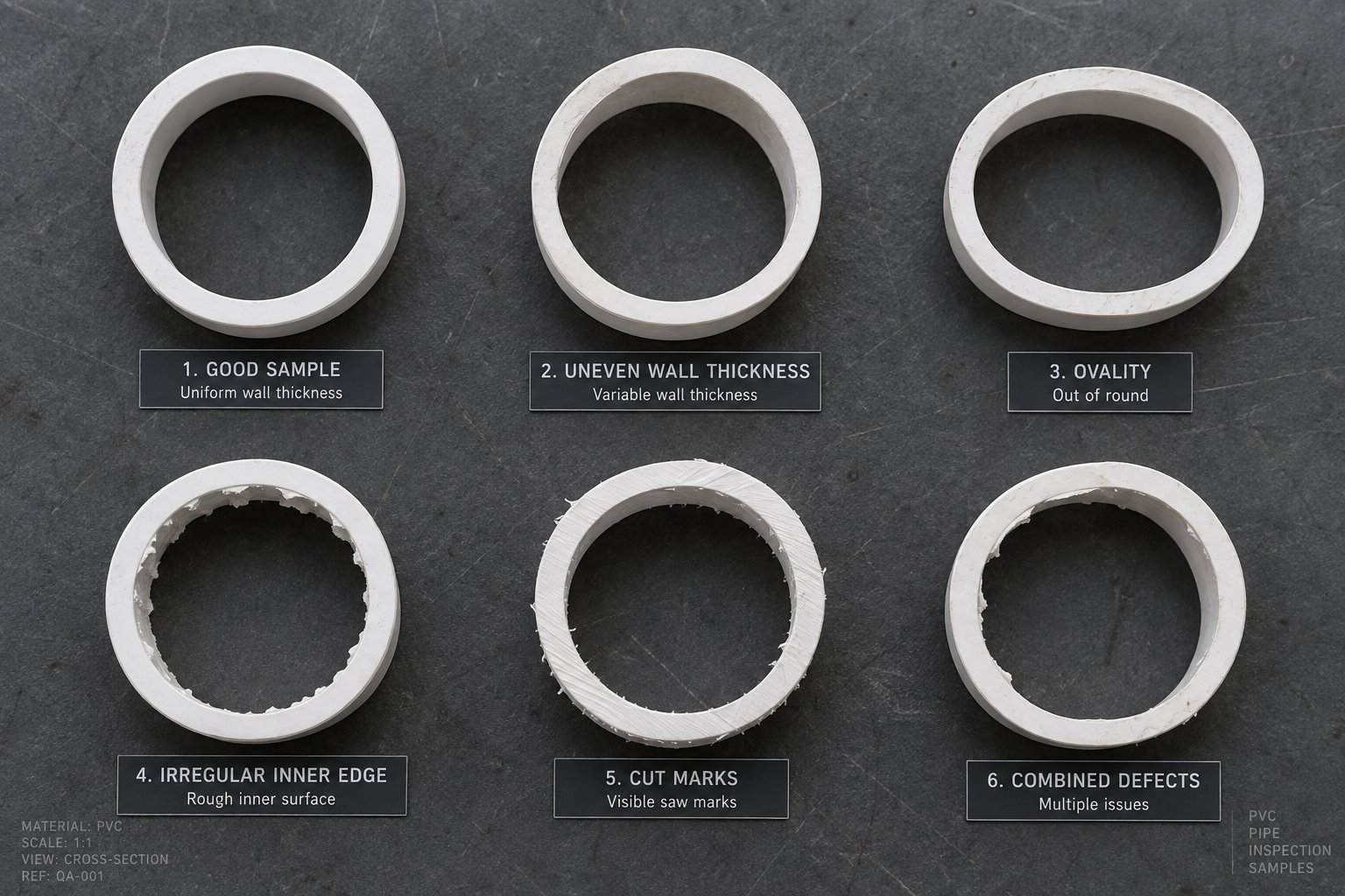
Dimensional defects are among the most consequential issues in pipe production because they directly compromise pressure ratings and joint integrity. When you measure a pipe and find uneven wall thickness — thick on one side, thin on the other — the most likely culprits trace back to three areas of the line.
First, die and mandrel misalignment. If the mandrel is not perfectly centered within the die body, the annular gap becomes wider on one side, pushing more material to that section. Adjusting the centering bolts during production usually resolves this, but persistent eccentricity may indicate a worn or damaged mandrel tip that needs replacement.
Second, inconsistent haul-off speed. As explained in the process overview, even a 2-3% speed fluctuation stretches or compresses the pipe wall unevenly. Servo-driven haul-offs with encoder feedback prevent this, while older belt-driven units with poor speed regulation are frequent offenders. Third, uneven barrel heating — if one zone runs hotter than its neighbors, the melt viscosity drops locally, creating flow imbalances that carry through to the die.
Ovality — a pipe that measures round on a gauge but oval in cross-section — is primarily a cooling and calibration issue. Insufficient vacuum in the calibration tank lets the pipe sag under gravity before it solidifies, pulling the top wall inward. Uneven water temperature inside the tank solidifies one side faster than the other, locking in asymmetry. And misaligned or worn sizing sleeves fail to hold the pipe's circular profile during the critical transition from soft extrudate to rigid tube. Well-designed vacuum calibration systems with multiple sleeves, stable vacuum pressure, and closed-loop cooling water temperature control are the primary defense against ovality.
Surface Defects and Discoloration Troubleshooting
Surface roughness shows up as a dull, matte, or scratched finish instead of the smooth, glossy appearance buyers expect. This defect usually points upstream to the extruder. Excessive melt temperature causes the PVC surface to partially degrade as it exits the die, producing a rough texture. A degraded screw and barrel — with worn flights that no longer provide consistent shear — delivers an unevenly plasticized melt with visible flow lines and rough patches. Contaminated raw material, even small amounts of degraded compound from a previous batch left in the barrel, creates streaks and surface imperfections.
Discoloration and yellowing signal thermal distress. PVC is thermally sensitive — push it beyond its processing window, and it begins releasing hydrochloric acid and breaking down. The common pvc pipe wall thickness variation causes overlap here, because the same barrel heating imbalances that produce uneven wall dimensions also create localized overheating that yellows the pipe. Excessive residence time compounds the problem: if material sits too long in the barrel or die head — due to low screw speed, oversized die channels, or production stoppages — degradation accelerates even at nominal temperatures.
Burn marks and black specks are the most alarming surface defects. They indicate material has stagnated and charred somewhere in the flow path. Dead spots inside the die head — corners or recesses where melt pools and overheats — are the usual source. Degraded material trapped in screw flight clearances contributes as well, especially when operators skip proper purging procedures between formulation changes or after extended shutdowns. Routine die head disassembly and cleaning, combined with disciplined purging protocols, prevents the buildup that leads to carbonized particles appearing in finished pipe.
Linking Machine Parameters to Pipe Quality Outcomes
Here is the pattern that experienced operators recognize: the vast majority of pvc pipe defects and solutions trace back to one of two root causes — plasticizing inconsistency in the extruder or parameter mismatches between extrusion speed, haul-off speed, and cooling capacity. A poorly plasticized melt produces rough surfaces, weak walls, and dimensional instability regardless of how well the downstream equipment is calibrated. A well-plasticized melt paired with mismatched haul-off speed or insufficient cooling still results in dimensional defects and residual stress.
This systemic view matters because it prevents operators from chasing symptoms. Adjusting the vacuum calibration tank won't fix wall thickness variation caused by a worn screw. Increasing cooling water flow won't eliminate yellowing caused by a barrel zone running 15 degrees above setpoint. Effective troubleshooting starts at the extruder and works downstream, checking melt quality first before adjusting calibration, cooling, or haul-off parameters.
The following table provides a quick-reference map for operators encountering common defects on the production floor:
| Defect | Probable Cause(s) | Recommended Corrective Action |
|---|---|---|
| Uneven wall thickness | Die/mandrel misalignment; inconsistent haul-off speed; uneven barrel zone temperatures | Re-center mandrel with adjusting bolts; check haul-off servo/encoder; verify all barrel zone temperatures match setpoints |
| Ovality (out-of-round) | Low or fluctuating vacuum in calibration tank; uneven cooling water temperature; worn or misaligned sizing sleeve | Stabilize vacuum pressure; check cooling water circulation and temperature uniformity; inspect and replace sizing sleeves |
| Surface roughness / dull finish | Excessive melt temperature; worn screw and barrel; contaminated raw material | Reduce barrel and die temperatures; measure screw/barrel wear and replace if needed; purge system and check material quality |
| Yellowing / discoloration | Barrel or die overheating; excessive residence time; degraded or insufficient stabilizer in formulation | Lower processing temperatures; increase screw speed to reduce residence time; verify stabilizer dosing in compound |
| Burn marks / black specks | Dead spots in die head; degraded material in screw flights; inadequate purging after shutdowns | Disassemble and clean die head; inspect screw flights and purge barrel thoroughly; implement documented purging protocol |
| Internal bubbles / voids | Moisture in raw material; trapped air from feed inconsistency; thermal degradation releasing gas | Check material drying and storage; ensure consistent feeding; reduce processing temperature if degradation suspected |
| Brittleness / cracking | Insufficient impact modifier; over-shearing in extruder; rapid or uneven cooling introducing residual stress | Review formulation for impact modifier levels; check screw speed and compression ratio; adjust cooling rate with staged water temperatures |
Print this table and post it near the operator control panel. When a defect appears, work through the probable causes from left to right, starting with the extruder-related items before moving to downstream equipment checks. Most issues resolve within one or two adjustments when you follow this structured approach rather than changing multiple parameters simultaneously — a common mistake that makes root-cause identification nearly impossible.
Catching defects in real time is essential, but preventing them altogether is a far better strategy. That means keeping every component on the line — especially the high-wear items like screws, barrels, die components, and vacuum seals — in proper operating condition before problems surface on the finished pipe.
Maintenance and Operational Best Practices for Production Lines
Preventing defects beats chasing them every time — and prevention starts with a disciplined maintenance routine. A well-maintained plastic pipe machine delivers consistent output for years, while a neglected one drifts quietly toward scrap rates, unplanned shutdowns, and premature component failure. The challenge? Wear happens gradually. Barrel bores widen by fractions of a millimeter per month, screw flights thin out imperceptibly, and vacuum seals lose their grip so slowly that operators compensate without realizing they're masking a deeper problem. By the time a defect appears on the finished pipe, the root cause has often been developing for weeks or months.
A structured pvc extruder maintenance schedule — organized by daily, weekly, monthly, and annual intervals — catches drift before it becomes downtime. Here is how to build that system around the components that matter most.
Screw and Barrel Wear Monitoring and Replacement Timing
The screw and barrel are the highest-impact wear items on any PVC pipe extrusion line. As discussed in the troubleshooting section, pvc pipe machine screw barrel wear directly degrades plasticizing consistency, reduces throughput at a given screw speed, and increases discharge temperatures. The mechanism is straightforward: as the flight clearance between screw tip and barrel bore widens, more material leaks backward over the flights instead of being conveyed forward. The extruder works harder to push less material, generating excess heat in the process.
How do you track this? Measure screw flight outside diameter and barrel bore inside diameter at regular intervals — monthly for high-utilization lines running two or three shifts, quarterly for single-shift operations. Take measurements at multiple points along the screw length: feed zone, compression zone, and metering zone. As Plastics Technology notes, the flight clearance for a new screw is typically the nominal screw diameter divided by 1,000 per side. A 3.5-inch screw, for example, starts with approximately 0.004 inches of clearance per side. Clearance beyond that baseline is wear.
When should you replace? Three common guidelines exist in the industry: when the flight clearance reaches four times the original new-screw clearance, when the hard-facing material on the flight tips is completely worn through, or when the rate reduction and discharge temperature increase make continued operation uneconomical. The best decision factors in the economics of your specific process. A non-critical drainage pipe line might tolerate higher wear levels, while a pressure-rated pipe operation — where dimensional tolerances are tight — may need replacement at just two times the original clearance.
Keep a spare screw in storage. Swapping a worn screw for a ready spare minimizes line downtime to the time needed for physical removal and installation, rather than the weeks a new screw order might require. One important caution from industry experts: a screw should never be refurbished more than three times, because repeated welding of new hard-facing onto the base material deteriorates the substrate and increases the risk of delamination. For barrels with iron-based bimetallic liners, the liner typically lasts about three times the service life of a screw — but barrel bore measurements should still be taken every time a screw is pulled for inspection.
Preventive Maintenance Schedules for Key Production Line Components
Screws and barrels get the most attention, but production stops just as often because of overlooked items downstream. A comprehensive extrusion line maintenance checklist covers every station, organized by frequency so that nothing falls through the cracks:
- Daily (10-15 minutes per shift):
- Listen for unusual motor or gearbox noise; check actual barrel zone temperatures against setpoints
- Confirm feed-throat cooling flow — a blocked circuit can stop feeding entirely and send operators chasing the wrong cause
- Record melt pressure at a fixed screw speed to spot trends (rising pressure may indicate die buildup or screen loading)
- Inspect die lip and adapter joints for resin buildup or leakage
- Verify cooling water level, temperature, spray coverage, and vacuum gauge readings
- Check haul-off belt contact, clamping force, and displayed speed
- Inspect cutter blade condition and cut timing accuracy
- Review control panel alarms, cabinet fan operation, and emergency stop function
- Weekly (during planned downtime):
- Check gearbox oil level and color — foaming or dark oil signals internal wear
- Inspect barrel heater band terminals for wiring discoloration or loose connections
- Review purge history and check for material residue from previous formulations
- Spot-check die bolt torque (thermal cycling loosens bolts over time)
- Clean water strainers, filters, and spray nozzles in cooling tanks
- Inspect vacuum calibration tank seals and calibration surfaces
- Measure haul-off belt wear and verify encoder feedback accuracy
- Sharpen or replace cutter blades; check clamp alignment
- Clean VFD heat sinks, tighten electrical terminals, and verify grounding connections
- Monthly (trend data collection):
- Measure screw flight diameter and barrel bore at feed, compression, and metering zones
- Record gearbox oil temperature under stable production load
- Test motor insulation resistance to detect moisture ingress or insulation breakdown
- Compare vacuum pump performance against baseline capacity
- Check cooling water quality — hardness, conductivity, and fouling indicators
- Measure cut-length variation across 10 or more samples for encoder or servo drift
- Back up PLC, HMI, and VFD parameters to prevent reprogramming delays after controller failures
- Annually (or at major scheduled shutdowns):
- Full gearbox oil change and internal inspection
- Complete thermocouple and heating element testing with replacement of degraded units
- Vacuum pump rebuild or vane replacement
- Die head full disassembly, cleaning, polishing, and inspection of flow channels for erosion or dead spots
- Barrel alignment verification — critical for long extruders where foundation shifts or thermal warping can push the barrel off-center
- Cooling tower and chiller system descaling and maintenance
Trend data is what separates proactive maintenance from emergency repair. A single melt pressure reading tells you where you are today; three months of readings plotted on a chart tell you where you're heading. When screw clearance, gearbox temperature, or vacuum capacity trends in the wrong direction for two or three consecutive readings, schedule the repair before the line forces a schedule on you.
Startup Shutdown and Purging Best Practices
How you start and stop the line matters as much as how you maintain it. PVC is thermally sensitive — leave it sitting in a hot barrel during an unplanned stoppage, and it degrades rapidly, releasing corrosive HCl gas that damages metal surfaces and producing carbonized particles that contaminate subsequent production runs.
For shutdown, Davis-Standard recommends a systematic approach: reduce operating speed at the end of a run to lower barrel temperatures gradually, then purge the current resin with a more thermally stable material introduced at a colder temperature. A base resin blended with an antioxidant masterbatch works well for this purpose. The goal is to displace all PVC from the barrel and die with a material that won't degrade if it sits at residual temperatures overnight or over a weekend.
For restart, bring the line to startup condition at a temperature lower than normal operating temperature, then heat-soak to ensure the purge material is fully molten before turning the screw. The lower initial temperature serves two purposes: it reduces exposure of stagnant polymer to high heat, and it maintains higher polymer viscosity during the initial purge, which creates scrubbing forces against the barrel wall and screw channels that help clean residual material. Only after the heat soak is complete and the polymer is fully molten should you begin ramping screw speed and transitioning to PVC compound.
When changing formulations — switching from a white to a gray compound, or from a standard UPVC blend to a CPVC formulation — thorough purging between runs prevents cross-contamination. Run a cleaning compound or the new formulation at elevated screw speed until the extrudate runs clean with no streaks, off-color material, or specks. Skipping this step is one of the most common causes of black specks and discoloration defects on the first pipes of a new production run.
These operational habits cost nothing beyond a few minutes of attention at each shift change — yet they prevent some of the most expensive problems in PVC pipe production: barrel corrosion from trapped degraded material, carbonized contamination that requires full die disassembly, and premature screw wear from running against abrasive degradation byproducts. Build them into standard operating procedures, train every operator to follow them, and you'll find that the line spends far more time making sellable pipe than recovering from avoidable problems.
Maintenance discipline and sound operating procedures keep a production line healthy day to day. But the bigger picture — building a consistently profitable PVC pipe operation — requires pulling together every element covered so far: machine selection, screw and barrel quality, process understanding, defect awareness, and a reliable supply chain for the components that inevitably wear out.
Putting It All Together for Reliable PVC Pipe Production
Running a profitable PVC pipe operation is not about getting one thing right — it is about getting everything aligned. The pipe specification drives machine selection. Machine selection determines screw geometry and barrel metallurgy. Screw and barrel quality governs melt consistency. And melt consistency either enables or undermines every downstream calibration, cooling, and cutting parameter on the line. Miss a link in that chain, and you spend your days troubleshooting symptoms instead of producing sellable pipe.
Whether you are commissioning your first production line, upgrading aging equipment, or trying to close the gap between current output quality and what your customers demand, the principles covered throughout this pvc pipe production line setup guide converge on a few high-impact decisions worth revisiting.
Key Takeaways for Machine Selection and Operation
Start with the pipe, not the machine. Your target diameter range, wall thickness class, pressure rating, and material type — UPVC, CPVC, or high-filler blends — define every equipment parameter downstream. Buyers who skip this step end up with oversized extruders running at half capacity or undersized lines bottlenecking within months of startup.
Match screw diameter to realistic throughput targets. A 65/132 mm conical twin-screw extruder suits mid-range pipe production up to about 250 mm diameter, while 80/156 mm or 92/188 mm configurations handle larger pipes and higher output volumes. Resist the temptation to buy the biggest machine available — an under-loaded extruder wastes energy and can actually deliver poorer melt quality because the screw operates outside its designed shear range.
Treat the screw and barrel as the production line's most critical consumable. These components wear progressively with every operating hour, and the degradation is often invisible until it shows up as dimensional defects, rising scrap rates, or increased energy consumption. Monthly flight-diameter and barrel-bore measurements catch drift early. Keeping a spare screw on hand cuts changeover downtime from weeks to hours.
Invest in bimetallic barrel and screw solutions when your formulation demands it. High calcium carbonate loading, CPVC processing, or continuous multi-shift operation all accelerate wear beyond what standard nitrided components can handle economically. The initial cost premium pays back through extended service intervals and more stable plasticizing — a point the industry data reinforces, showing wear reduction of up to 60% and total cost-of-ownership savings approaching 50% over three years.
Build defect troubleshooting into daily operations, not just emergency response. The quick-reference defect table from the previous section belongs on the wall next to every operator control panel. Most quality problems trace back to plasticizing inconsistency in the extruder or parameter mismatches between extrusion speed, haul-off speed, and cooling capacity — and resolving them systematically saves far more time than adjusting multiple parameters at random.
Finally, disciplined startup, shutdown, and purging procedures cost nothing but a few minutes of attention per shift — yet they prevent barrel corrosion, carbonized contamination, and premature wear that generate some of the most expensive downtime events in PVC pipe manufacturing.
Building a Reliable Supply Chain for Screw and Barrel Components
Here is a reality that every experienced pipe manufacturer understands: the line only runs as well as its weakest wear component. You can specify the best extruder, install premium PLCs and VFDs, and train operators to perfection — but when the screw flights wear past tolerance or the barrel bore opens up, production quality drops regardless. And at that point, the speed and quality of your replacement component supply chain determines how quickly you get back to full performance.
Choosing a conical twin screw barrel supplier is not the same as ordering commodity hardware. PVC processing imposes specific demands — moderate compression ratios for thermal sensitivity, corrosion-resistant alloys for HCl exposure, and precise flight geometry that transitions smoothly between conveying, compression, and metering zones without dead spots. A supplier who understands these requirements delivers components engineered for stable plasticizing, not just dimensionally correct parts that fit the machine.
NANHAIYA is one such specialist, engineering conical twin screw barrels specifically for PVC pipe, profile, board, foam board, and WPC extrusion lines. Their focus on custom and replacement barrels — with bimetallic options and application-specific screw geometry — makes them a practical resource for manufacturers who need components matched to their exact formulation and output requirements. If you are evaluating your screw and barrel options, whether for a new line or to replace worn components on an existing one, exploring what a dedicated barrel specialist can offer is a worthwhile next step.
Plasticizing quality is the foundation of every successful PVC pipe production line. The screw and barrel generate the melt — and the melt determines everything: dimensional accuracy, surface finish, mechanical strength, and production uptime. Invest in that foundation first, maintain it rigorously, and every other component on the line performs closer to its potential.
The path from raw PVC resin to defect-free, dimensionally precise pipe is long — 30 to 50 meters of synchronized equipment, dozens of interlinked process parameters, and thousands of operating hours between major maintenance intervals. But the core principle is simple. Get the melt right, keep the line maintained, and work with suppliers who understand what PVC demands. Everything else follows from there.
Frequently Asked Questions About PVC Pipe Manufacturing Machines
1. What are the main components of a PVC pipe manufacturing machine?
A complete PVC pipe manufacturing machine is actually a synchronized production line comprising a high-speed mixer and cooling mixer for compound preparation, an automatic feeder, a conical twin-screw extruder (the core plasticizing unit), an extrusion die head with mandrel, a vacuum calibration/sizing tank, spray cooling tanks, a caterpillar or belt haul-off unit, a planetary cutting machine, a belling/socketing machine, and an automatic stacker. The entire line typically stretches 30 to 50 meters and relies on PLC-coordinated control systems — preferably using reputable brands like Siemens, ABB, or Schneider — to keep all stations running in precise synchronization for consistent pipe quality.
2. Why are conical twin-screw extruders preferred for PVC pipe production?
Conical twin-screw extruders are the industry standard for rigid PVC because their tapered geometry solves three simultaneous challenges. The wide feed end delivers high torque to intake low-bulk-density PVC dry blend, the tapering channel progressively compresses and plasticizes the material, and the narrow discharge end builds pressure for uniform melt delivery to the die. This design also keeps the gearbox compact and limits the material's heat exposure, reducing the risk of thermal degradation — a critical concern since PVC releases corrosive hydrochloric acid when overheated. Specialist suppliers like NANHAIYA (nhyscrews.com) engineer conical twin screw barrels with precise geometry and bimetallic options specifically for stable PVC plasticizing performance.
3. How do I choose the right size PVC pipe extrusion line for my production needs?
Start by defining your target pipe diameter range, wall thickness class, pressure rating, material type (UPVC, CPVC, or high-filler blends), and realistic hourly output in kilograms. The conical twin-screw diameter is the best predictor of capacity: a 65/132 mm extruder handles roughly 180-400 kg/hr for pipes up to 250 mm, while an 80/156 mm or 92/188 mm unit covers larger diameters and higher throughputs. Factor in real-world output losses of 15-25% below nameplate ratings due to startups, changeovers, and stoppages. Also account for total investment beyond the machine itself — utilities, floor space, tooling sets, installation, operator training, and initial spare parts typically add 25-40% above the core equipment cost.
4. What causes wall thickness variation in PVC pipes, and how can it be fixed?
Wall thickness variation in PVC pipes typically stems from three machine-related causes. First, die and mandrel misalignment creates an uneven annular gap, pushing more material to one side — corrected by adjusting the centering bolts. Second, inconsistent haul-off speed stretches or compresses the pipe wall unevenly, which servo-driven haul-offs with encoder feedback can prevent. Third, uneven barrel heating produces localized melt viscosity differences that carry through to the die. Most dimensional defects ultimately trace back to plasticizing inconsistency in the extruder or parameter mismatches between extrusion speed, haul-off speed, and cooling capacity. Effective troubleshooting always starts at the extruder and works downstream.
5. How often should screws and barrels be replaced on a PVC pipe extruder?
PVC extruder screws typically require replacement every one to four years, depending on formulation abrasiveness, filler loading, and operating hours. Monitor wear by measuring screw flight outside diameter and barrel bore inside diameter monthly for multi-shift operations or quarterly for single-shift lines. Replace when flight clearance reaches four times the original new-screw specification, when hard-facing is worn through, or when throughput loss and rising discharge temperatures make continued operation uneconomical. Bimetallic screw and barrel solutions — such as those offered by NANHAIYA for PVC pipe, profile, and board extrusion — extend service intervals significantly, with industry data showing wear reduction of up to 60% compared to standard nitrided components. Keep a spare screw on hand to minimize changeover downtime.
Written by
Nanhaiya Technical Team
Zhoushan Nanhaiya Plastic Machinery Co., Ltd.
The Nanhaiya technical team supports screw and barrel manufacturing projects through application review, technical communication, custom manufacturing coordination, and production and quality control.
Discuss Your Application
Related Articles
More insights on screw barrel technology and plastics processing.

What Nobody Tells You About Screw Barrel For Plastic Machine Design
Oct 10, 2026
Learn how screw barrel for plastic machine design affects melt quality, throughput, and wear life. Covers geometry, resin matching, troubleshooting, and sourcing.
Read Article
Single Screw Extruder for Sheet: Stop Guessing, Start Specifying
Oct 9, 2026
Learn how to specify a single screw extruder for sheet production. Covers screw geometry, resin-specific processing, troubleshooting, and maintenance best practices.
Read Article
PE Pipe Extruder Machine: What Datasheets Won't Tell You
Oct 9, 2026
Learn how a PE pipe extruder machine works, key specs explained, material grade selection, maintenance tips, and buyer guidance beyond the datasheet.
Read ArticleLooking for something else?
Search by material, symptom or product and jump straight to the relevant page.
These are navigation suggestions based on keyword matching — not a quotation, not a delivery commitment, and not a substitute for engineering review. Final specification is confirmed by our engineers against your drawings and processed material.
Need help with screw barrel selection?
Share your machine model, processed material and application. Our team can help with pricing and technical support.