

What Is PVC Pipe Extrusion and Why It Dominates Modern Infrastructure
Defining the PVC Pipe Extrusion Process
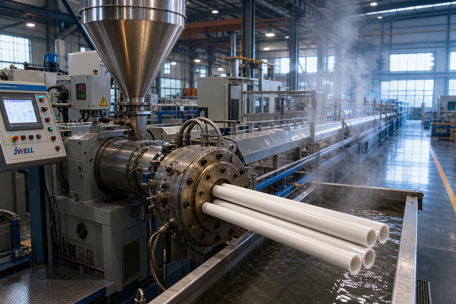
PVC pipe extrusion is a continuous manufacturing process in which a heated polyvinyl chloride compound is forced through a shaped annular die by a rotating screw mechanism, producing hollow cylindrical profiles at consistent dimensions and wall thicknesses suitable for pressure and non-pressure applications.
Here is what makes this process fundamentally different from extruding other plastics: PVC does not truly melt. Unlike polyolefins such as polyethylene or polypropylene, PVC is a thermally sensitive amorphous polymer that undergoes particle fusion — a progressive bonding of resin particles under controlled heat and shear — rather than flowing as a conventional melt. Under extrusion conditions, PVC behaves more like a rubber-like solid, forming a structure of tie molecules and crystallites in the pipe wall. This single characteristic shapes every equipment choice, temperature setting, and process decision downstream.
Why PVC Remains the Dominant Pipe Material
Imagine a material that resists corrosion, weighs a fraction of its metal counterparts, lasts decades underground, and costs less to produce and install. That is precisely why PVC dominates water supply, drainage, irrigation, and electrical conduit markets worldwide.
PVC is two to three times stronger and stiffer than polyolefin alternatives, exhibits lower diffusion through the pipe wall — critical for drinking water applications in contaminated soil — and shows remarkable resistance to corrosion and chemical attack unlike steel or concrete. The industry's transition toward lead-free stabilizers further strengthens PVC's position. Modern hybrid calcium-zinc and organic-based stabilizer systems now enable multiple reprocessing cycles without severe molecular breakdown, supporting circular-economy goals.
Key advantages of PVC pipe include:
- Corrosion resistance — immune to rust, chemical degradation, and chlorinated water attack
- Smooth bore — reduced friction loss for superior hydraulic efficiency
- Light weight — faster installation and lower transportation costs
- Long service life — proven performance exceeding 50 years in buried applications
- Cost-effectiveness — lower production and installation costs versus steel and concrete
- Recyclability — compatible with modern lead-free stabilizers that maintain material quality through reprocessing
Who This Process Guide Serves
This article is built for extrusion engineers, plant operators, and production managers who need more than surface-level overviews. You will find high-level material science layered with actionable process parameters, equipment selection rationale, and structured troubleshooting — the kind of vinyl extrusion depth that typical guides skip entirely. Whether you are optimizing an existing PVC extrusion line or specifying equipment for a new installation, the chapters ahead address the narrow processing window that defines success or failure in this uniquely demanding process.
That processing window — and the material science behind it — is exactly where the real engineering challenge begins.
PVC Material Science and the Narrow Processing Window
Most guides on extrusion PVC treat the material as just another thermoplastic. Feed it, heat it, push it through a die. But PVC is nothing like polyethylene or polypropylene. Its amorphous structure, unusually high glass-transition temperature (around 80 °C), and extreme thermal sensitivity create a processing window so narrow that a misunderstanding of even one variable — molecular weight selection, gelation behavior, or degradation chemistry — can ruin an entire production run. This is the materials-science foundation that separates competent PVC pipe operations from those constantly fighting defects.
Understanding PVC K-Value and Molecular Weight
When selecting PVC resin for extrusion, the first parameter you will encounter is K-value. Derived from intrinsic viscosity measurements using the Fikentscher equation, K-value is the industry-standard indicator of molecular weight for polyvinyl chloride. The relationship is straightforward: higher K-value means higher molecular weight, which translates to greater tensile strength, better impact resistance — and significantly more energy required to achieve fusion.
For rigid pipe applications, K-65 to K-68 resins dominate. K-65 offers balanced processability and mechanical performance for general-purpose pressure pipe, while K-67 and K-68 grades deliver the extra strength needed for higher-pressure ratings and demanding structural applications. However, this strength comes at a cost. Higher K-value resins exhibit greater melt viscosity, demand higher extruder torque, require longer fusion times, and consume more specific energy per kilogram of output.
You will notice this tradeoff directly on the production floor. A jump from K-65 to K-68 resin may require screw speed adjustments, revised temperature profiles, and potentially different screw geometry to accommodate the increased resistance to fusion. Selecting the wrong K-value for your extruder's torque capacity is one of the fastest paths to incomplete gelation and substandard pipe.
Gelation Theory and Particle Fusion
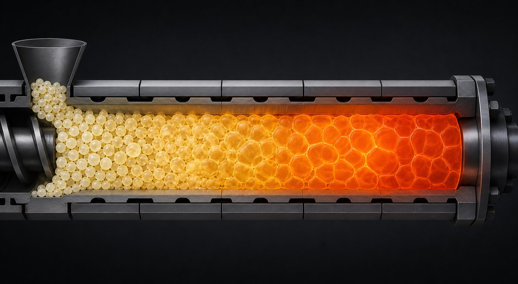
Here is the concept that trips up operators who transfer from polyolefin extrusion: extruded PVC does not truly melt. Instead, PVC resin particles undergo a progressive fusion process called gelation, where heat and mechanical shear break down the original grain structure and bond primary particles into a continuous, entangled network. Understanding the PVC gelation process is essential because the degree to which this fusion occurs directly determines the pipe's mechanical properties.
The gelation sequence unfolds in distinct stages:
- Grain breakdown — The 100-150 micrometer resin grains fracture under shear, exposing smaller sub-grains and primary particles roughly 1 micrometer in size.
- Primary particle compaction — Heat and pressure compress these particles into dense contact, collapsing internal porosity.
- Inter-particle fusion — Molecular chains at particle boundaries begin to interdiffuse, creating tie molecules that bridge adjacent particles.
- Network formation — Extensive chain entanglement produces a continuous polymer network with crystallite junctions acting as physical crosslinks.
The critical insight? Both under-gelation and over-gelation destroy pipe quality. Incomplete fusion leaves weak boundaries between primary particles, resulting in poor impact strength and susceptibility to crack propagation. Push too far, and you consume the compound's thermal stability budget, triggering degradation before the pipe even reaches the calibration tank.
PVC pipe quality is fundamentally determined by achieving optimal gelation — typically 60-80% — where mechanical properties peak without triggering thermal degradation.
This sweet spot is not a fixed number. It shifts depending on the K-value of the resin, the stabilizer system, the lubricant balance, and the specific shear and temperature history delivered by your extruder. Hitting it consistently, run after run, is the central skill of PVC pipe production.
Thermal Degradation and the Processing Window
Imagine a processing corridor barely 40 degrees wide. Below roughly 170 °C, rigid PVC compound refuses to fuse properly. Above approximately 210 °C, the polymer begins to decompose. That is the reality of extrusion PVC — a window so tight that every barrel zone, every die temperature, and every second of residence time matters.
The degradation mechanism is dehydrochlorination — the heat-induced removal of hydrogen chloride (HCl) from the PVC chain. This reaction begins at structurally weak points along the polymer backbone: allylic chlorine sites, tertiary chlorine atoms, and unsaturated chain ends that formed during polymerization. Once HCl detaches, it leaves behind conjugated double-bond sequences (polyenes) responsible for the progressive yellowing, browning, and eventual blackening of degraded PVC.
What makes this especially dangerous is the autocatalytic nature of the process. Released HCl does not simply escape. It lingers in the melt, in barrel dead zones, and in die channels — actively catalyzing further dehydrochlorination. A small pocket of overheated material can accelerate degradation throughout the entire melt stream. This is fundamentally different from processing polyolefins, where modest temperature overshoots cause property shifts but rarely catastrophic decomposition.
For extrusion engineers, the implications are clear. Temperature control in PVC pipe production is not about hitting approximate setpoints. It demands precise zone-by-zone management where every degree of unnecessary heat and every second of excess residence time consumes finite thermal stability that the stabilizer system cannot restore. This is why screw design, die geometry, lubricant balance, and stabilizer selection are not independent choices — they are interlocking decisions that collectively determine whether your process stays inside the narrow window or drifts outside it.
The compound recipe is what gives you the tools to navigate that window. And formulating a PVC pipe compound involves far more than choosing a resin grade.
PVC Formulation and Compounding Essentials for Pipe Production
PVC resin, on its own, is essentially unprocessable. It would degrade almost immediately at extrusion temperatures without protective chemistry, stick aggressively to metal surfaces without lubrication, and shatter under impact without toughening agents. Every successful PVC extrusion process depends on a carefully engineered compound — a recipe where each additive serves a specific function and where the balance between components determines whether the line runs smoothly or fights you at every turn.
Think of it this way: the resin provides the backbone, but the additive package determines how that backbone behaves under the heat, shear, and pressure of the extruder. Getting this recipe right is the difference between consistent PVC extrusions with excellent surface finish and a production run plagued by plate-out, melt fracture, and dimensional instability.
Essential Additive Categories for PVC Pipe Compounds
PVC compounds for extrusion contain six to eight additive categories, each loaded at specific concentrations measured in phr (parts per hundred resin). The table below outlines the essential components found in a typical rigid PVC pipe formulation:
| Additive Type | Function | Typical Loading Range (phr) |
|---|---|---|
| Heat Stabilizers (Tin-based) | Prevent thermal degradation by scavenging HCl and interrupting dehydrochlorination | 1.0 - 2.5 |
| Heat Stabilizers (Calcium-Zinc, lead-free) | Same protective function with improved environmental and regulatory profile | 2.5 - 5.0 |
| Internal Lubricants (e.g., oxidized PE wax, glycerol esters) | Reduce inter-particle and inter-molecular friction within the PVC melt to lower melt viscosity | 0.3 - 1.2 |
| External Lubricants (e.g., paraffin wax, PE wax) | Reduce adhesion between the PVC melt and hot metal surfaces of screws, barrel, and die | 0.2 - 1.0 |
| Processing Aids (acrylic-based, e.g., MMA copolymers) | Promote faster fusion, improve melt elasticity, and enhance surface quality | 0.5 - 2.0 |
| Impact Modifiers (CPE or acrylic-based) | Improve toughness and resistance to brittle fracture, especially at low temperatures | 3.0 - 8.0 |
| Calcium Carbonate (CaCO3) Filler | Reduce material cost, increase stiffness, and improve dimensional stability | 3.0 - 20.0 |
| Titanium Dioxide (TiO2) | Provide UV protection, opacity, and whiteness for outdoor-exposed pipe | 1.0 - 4.0 |
Notice how the lubricant system contains both internal and external components. Their ratio is critical — too much external lubricant delays fusion and causes plate-out on screws and die surfaces, while too little leads to sticking, increased torque, and melt fracture at the die exit. The processing aid works synergistically with the lubricant system by accelerating fusion to compensate for the fusion delay that external lubricants inherently create.
Dry-Blend vs. Pellet Processing
Before the compound reaches the extruder, it must be prepared in one of two forms: dry-blend (powder) or pre-compounded pellets. For rigid PVC pipe production, dry-blend dominates — and for good reason.
The PVC extrusion process imposes a strict thermal budget. Every degree of heat history consumed before material enters the pipe extruder is stability you cannot recover. Dry-blending combines resin and additives in a high-speed mixer (typically reaching 110-120 °C through frictional heating), followed by transfer to a cooling mixer that brings the homogeneous powder back to ambient temperature. This preserves nearly the entire thermal stability budget for the actual pipe extrusion step.
Pellet processing adds a full compounding extrusion pass before the pipe line — imposing additional heat history, shear history, and cost. However, it delivers benefits that some applications demand. PVC compound pellets offer superior lot-to-lot consistency, eliminate the need for in-house formulation expertise, and feed reliably into single-screw extruders that struggle with powder intake. For specialty color-matched products or operations without dedicated mixing equipment, the compound route makes strategic sense despite the 8-12% cost premium.
The equipment implications are significant. Dry-blend processing requires upstream investment in high-speed hot/cold mixer systems, accurate weighing and dosing equipment, and climate-controlled powder storage. The extruder itself must handle low-bulk-density powder efficiently — which is why twin-screw designs with their positive conveying action dominate dry-blend PVC pipe lines, while single-screw extruders work better with pre-compounded pellets that flow freely and do not bridge in the feed throat.
How Compound Quality Drives Extrusion Outcomes
Here is where formulation directly intersects with production floor reality. Every additive interaction shows up in the extruder's behavior and in the final pipe quality:
- Poor stabilizer dispersion — creates localized zones of inadequate thermal protection, leading to degraded material depositing on screw flights and barrel walls (plate-out), which eventually contaminates the melt stream and produces discolored specks in the pipe wall.
- Insufficient or imbalanced lubricant system — causes excessive melt adhesion to metal surfaces, increasing screw torque, generating unwanted frictional heat, and producing melt fracture that appears as surface roughness or shark-skinning at the die exit.
- Excess CaCO3 filler loading — while economically attractive, accelerates abrasive wear on screw flights, barrel linings, and die land surfaces. High filler content also reduces impact strength and narrows the already tight processing window by increasing melt viscosity.
- Inadequate processing aid levels — delays gelation onset, forcing operators to increase barrel temperatures or reduce throughput to achieve acceptable fusion, which in turn consumes more thermal stability budget.
Sounds complex? It is. The compound is not simply a list of ingredients — it is a system of interdependent variables where changing one loading level cascades through fusion behavior, thermal stability, melt rheology, and ultimately the mechanical properties of the finished pipe. Mastering PVC compounds for extrusion means understanding these interactions well enough to adjust formulations when resin lots change, ambient conditions shift, or production targets demand higher throughput.
The compound delivers the material to the extruder in a processable state. But the extruder itself — specifically the screw and barrel system that applies heat and shear to transform that compound into fused pipe — introduces its own set of engineering decisions that are equally consequential.
Twin-Screw vs. Single-Screw Extruders for PVC Pipe Processing
PVC compound arrives at the extruder as a low-bulk-density powder that slides against metal, degrades within a razor-thin temperature corridor, and releases corrosive gas if mistreated. These behaviors do not merely influence which PVC extruder you choose — they dictate it. The screw and barrel assembly must positively convey a powder that refuses to grip barrel walls, deliver tightly controlled shear without overshooting the degradation threshold, and resist both chemical attack and abrasive wear from calcium carbonate fillers. Getting this wrong means fighting the material every hour of every shift.
Why Conical Twin-Screw Extruders Dominate PVC Pipe Lines
Walk into any modern rigid PVC pipe plant and you will almost certainly find conical counter-rotating twin-screw extruders at the heart of the line. This is not convention — it is engineering logic built around PVC's unique behavior.
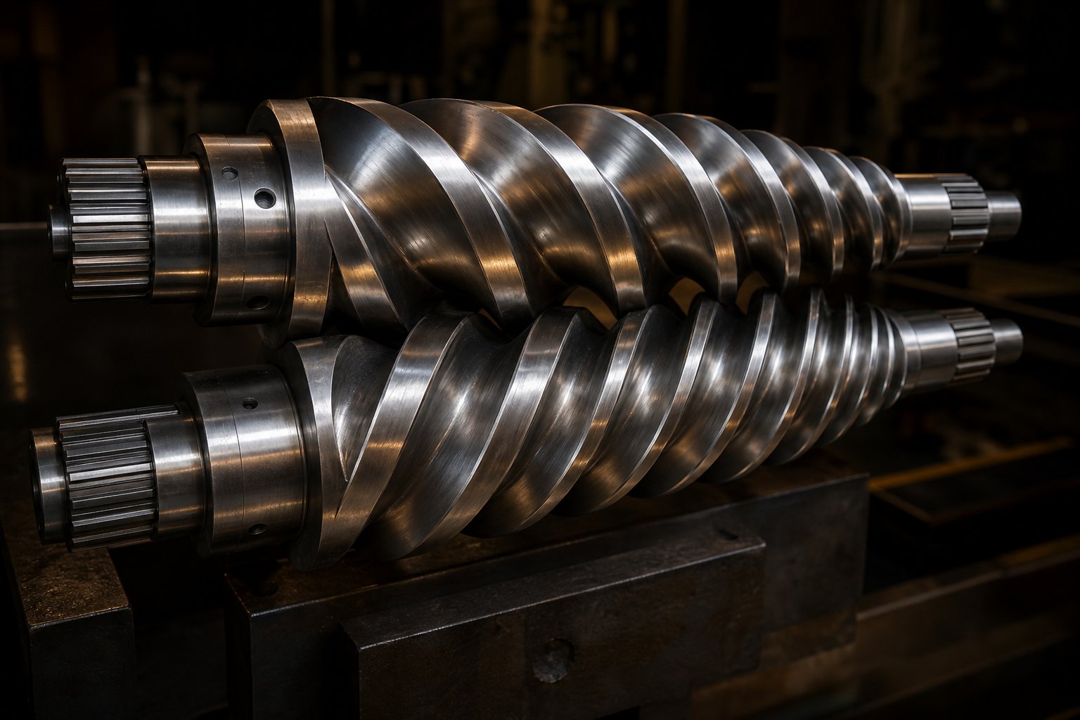
The conical geometry solves multiple problems simultaneously. At the feed end, the large-diameter screw opening — often twice the size of the metering section — accepts low-bulk-density dry-blend powder without bridging or starving. As the screws taper toward the discharge, material is progressively compressed, collapsing trapped air and driving particle-to-particle contact that initiates gelation. Conical twin-screw extruders are essentially positive displacement pumps, independent of the frictional forces that PVC's wall-slip behavior undermines. Material moves forward because the intermeshing screw geometry forces it forward — not because it grips the barrel wall.
The counter-rotating design generates controlled, low-shear mixing. Imagine two gears turning inward: material is pulled into the nip between flights, subjected to brief, intense shearing in the milling gap, then released. This delivers the energy needed for fusion without the sustained high shear that would push PVC past its degradation threshold. The fully intermeshing flights also create a self-wiping action, continuously scraping material from screw surfaces and eliminating the stagnant pockets where PVC would overheat and decompose.
Energy efficiency adds another advantage. Because plasticizing rate in a conical PVC pipe extruder is primarily controlled through barrel and screw temperature rather than through shear, these machines run at roughly 50% lower energy consumption compared to single-screw alternatives processing the same output. The smaller metering-zone diameter also reduces axial forces on the screws and thrust bearings, extending mechanical service life.
Single-Screw Limitations for Rigid PVC
Single-screw extruders remain the workhorse of polyolefin processing, but rigid PVC exposes their fundamental limitations. The core issue is conveying mechanism. A single screw relies on friction between the polymer and the barrel wall to drag material forward. PVC's wall-slip behavior — its tendency to slide against hot metal rather than grip it — directly undermines this mechanism, leading to inconsistent feed rates, output surging, and unpredictable melt pressure.
Powder feeding compounds the problem. Dry-blend PVC has a bulk density roughly 40-50% of its solid density. A single-screw feed throat, designed for free-flowing pellets, struggles with this fluffy powder. Bridging in the hopper, uneven screw-channel filling, and erratic output are common when operators attempt to run PVC dry-blend through single-screw machines.
That said, single-screw extruders still hold a legitimate role in specific PVC applications. Flexible PVC compounds — heavily plasticized and pre-compounded into pellets — feed and convey reliably on single-screw systems. Some PVC profile extruder operations also use single-screw machines with pre-compounded pellets where the additional compounding cost is offset by simpler equipment and lower capital investment. For rigid PVC pipe at production-scale throughput, however, the twin-screw design's positive displacement and powder-handling capability remain unmatched.
Screw Design Parameters That Matter for PVC Pipe
Selecting the right extruder type is only half the equation. The screw and barrel geometry within that extruder determines whether your process achieves consistent gelation, stable output, and acceptable wear life.
L/D ratio — the length-to-diameter ratio — controls how much processing the material receives. Conical twin-screw extruders for PVC pipe typically operate in the 20:1 to 28:1 L/D range. Shorter L/D ratios risk incomplete fusion; longer ratios extend residence time, providing more thorough gelation and homogenization but increasing the risk of thermal degradation if temperature control is not precise. Modern designs trend toward longer processing units with reduced taper angles, achieving surface areas comparable to parallel twin-screw extruders at L/D ratios approaching 28:1.
Compression ratio works in concert with the conical taper. As screw diameter decreases from feed to metering, the channel volume shrinks progressively. This gradual compression controls shear energy input — avoiding the sudden compression spikes that generate localized hot spots in PVC melt. Lower diameter at the metering section means lower peripheral screw speed at constant RPM, which translates to reduced shear rate, lower temperature rise, and less die swell.
The comparison table below highlights where each extruder architecture fits in PVC processing:
| Feature | Conical Twin-Screw | Parallel Twin-Screw | Single-Screw |
|---|---|---|---|
| Powder (dry-blend) feed capability | Excellent — large feed opening accepts low-bulk-density powder | Good — requires adapted feed geometry | Poor — designed for pellets; powder causes bridging |
| Shear control | Excellent — low shear in metering zone due to reduced diameter | Moderate — uniform shear along full length | Limited — relies on barrel friction, prone to hot spots |
| Mixing and homogenization | Very good — intermeshing, self-wiping action | Excellent — larger intermeshing surface area along full length | Moderate — limited distributive mixing without special screw elements |
| Positive displacement conveying | Yes — independent of wall friction | Yes — independent of wall friction | No — depends on barrel-wall friction |
| Typical PVC application | Rigid PVC pipe, profile, sheet | Rigid PVC pipe (especially large diameter), compounding | Flexible PVC, pellet-fed profile, small-diameter pipe |
| Energy efficiency for rigid PVC | High — temperature-controlled plasticizing at lower amperage | Moderate — higher shear energy input | Lower — friction-dependent, higher specific energy |
Barrel and screw metallurgy deserve equal attention, because PVC compounds attack processing equipment from two directions simultaneously. HCl gas released during processing corrodes standard steel surfaces, while CaCO3 filler — loaded anywhere from 3 to 20 phr — grinds aggressively against screw flights and barrel linings. The combination demands specialized protection.
Bimetallic barrel linings — featuring nickel-rich alloy inner layers — offer service lives at least four times longer than standard nitrided barrels in PVC service, with corrosion-resistant grades lasting over ten times longer in aggressive processing environments. Screw surfaces benefit from tungsten carbide coatings or hardfacing treatments that resist abrasive wear without compromising the precise flight tolerances that positive-displacement conveying demands. As screw-barrel clearance increases from wear, conveying efficiency drops — output losses of up to 60 pounds per hour have been documented from relatively small clearance increases in mid-size extruders.
For manufacturers running CaCO3-filled PVC compounds, sourcing barrels engineered specifically for these dual demands is essential. Specialists like NANHAIYA engineer conical twin screw barrel solutions purpose-built for PVC pipe, profile, sheet, and WPC extrusion — with metallurgical specifications matched to the corrosion and abrasion profile of each application. Whether you need a custom barrel for a new line or a drop-in replacement to restore plasticizing consistency on an aging PVC extruder, application-specific barrel design directly impacts output stability, dimensional accuracy, and long-term wear resistance.
Choosing the right extruder architecture and screw-barrel system establishes the mechanical foundation. But that foundation only performs when each processing zone along the barrel is set to the precise temperature and pressure profile that PVC's narrow window demands — a zone-by-zone calibration where the science of gelation meets the reality of production floor control.
Zone-by-Zone Process Walkthrough with Temperature Profile Logic
A conical twin-screw extruder is not a single processor — it is a sequence of thermally distinct environments, each performing a specific physical transformation on the PVC compound. Set one zone wrong and you either starve the next zone of properly prepared material or push the compound past the degradation threshold before it ever reaches the die. Every PVC extrusion machine operates on this principle, yet most process guides treat the barrel as a single black box with an input and an output. The reality is far more nuanced.
Feed Zone and Material Intake
PVC dry-blend enters the extruder through a feed hopper connected to either a gravimetric or volumetric feeder. Gravimetric systems — which measure actual mass flow — deliver superior consistency because they compensate for the bulk density variations that plague PVC powder. Even small fluctuations in feed rate ripple downstream as wall thickness variation, pressure swings, and inconsistent gelation.
Temperature in the feed zone must remain relatively low, typically 150-165 °C for rigid PVC pipe compounds. Why so conservative? Two reasons. First, premature fusion creates agglomerated lumps that bridge across the screw channels, choking material flow and starving downstream zones. Second, the feed zone must allow trapped air between powder particles to escape back through the hopper before the material compacts — a process that higher temperatures would disrupt by softening particle surfaces prematurely.
Twin-screw systems introduce an additional consideration: starve-feeding versus flood-feeding. In flood-feeding, the hopper gravity-fills the screws and the extruder determines throughput. Starve-feeding uses a metering device to control the exact mass entering the screws, decoupling feed rate from screw speed. This separation allows operators to optimize screw speed for gelation quality independently of output rate — a valuable degree of freedom when processing thermally sensitive PVC where shear history directly impacts the degradation budget.
Compression and Plasticizing Zones
As the conical screws taper inward, channel volume decreases progressively. Material that entered as a loose powder is now compressed, de-aerated, and heated into a dense, partially fused mass. This is where the real transformation occurs — and where the most critical temperature decisions are made.
The compression zone typically operates at 165-175 °C, rising gradually from the feed section. This progressive increase follows a deliberate philosophy: each zone adds just enough thermal energy to advance gelation without overshooting the degradation boundary. PVC particles undergo compaction and inter-particle fusion here — primary particle boundaries begin to interdiffuse, tie molecules bridge across former grain boundaries, and the material transitions from a granular solid to a cohesive, rubber-like mass.
A critical distinction separates this from polyolefin processing. In polyethylene extrusion, the compression zone melts crystalline regions — a phase transition with a clear melting point. PVC undergoes no such phase change. Instead, gelation is a gradual, shear-assisted process where frictional heat from screw rotation supplements barrel heater input. The balance between these two heat sources matters enormously. Excessive screw speed generates too much frictional heat, pushing temperatures beyond the setpoint and consuming thermal stability budget that barrel cooling cannot fully recover. Insufficient speed leaves the compound under-fused, producing pipe with poor impact strength and visible grain boundaries under microscopic examination.
Improper settings in this zone announce themselves immediately. Too-low temperatures produce torque spikes as the screws fight against un-fused, highly viscous material. Too-high temperatures trigger the autocatalytic degradation cascade discussed earlier — releasing HCl gas that accelerates decomposition throughout the remaining barrel length.
Metering Zone, Adapter, and Die Head
The metering zone serves as the final homogenization stage. By this point, PVC should be fully fused to the target 60-80% gelation level. The metering section's job is to deliver this fused compound at uniform temperature, consistent viscosity, and stable pressure to the die — operating in the 170-185 °C range, while the adapter and die zone typically run at 175-190 °C.
Overheating in the metering zone is particularly dangerous because material has already consumed a significant portion of its thermal stability budget during compression and plasticizing. A color shift appearing at this stage — even slight yellowing — signals that the compound is running out of stabilizer capacity with no opportunity to recover downstream.
The adapter transitions material from the extruder's circular barrel cross-section to the annular geometry required for pipe. This transition must occur without dead spots — low-flow corners where PVC stagnates, overheats, and degrades into carbonized particles that eventually dislodge and contaminate the product stream.
Die head design for PVC pipe centers on two primary architectures. Spider dies use radial support legs to hold the central mandrel in position. The melt stream splits around these legs and recombines on the other side, creating weld lines (spider lines) in the pipe wall. Spider dies are favored for PVC specifically because they offer short residence time — critical for a thermally sensitive polymer — along with low back pressure and symmetrical melt distribution. The quality of spider-line welds depends primarily on the deformation the melt undergoes after recombination: greater deformation energizes molecular chains to interdiffuse across the weld boundary, producing stronger joints.
Spiral-mandrel dies take a different approach. Multiple spiral channels carved into the mandrel surface gradually overlap, distributing the melt circumferentially and eliminating distinct weld lines entirely. These dies produce superior wall uniformity but impose longer residence times and higher back pressure — a meaningful tradeoff when processing PVC, where every additional second at temperature erodes the stability margin.
Every degree of unnecessary temperature and every second of excess residence time in PVC extrusion consumes thermal stability budget that cannot be recovered.
Process Control Parameters
Running a PVC pipe line within the narrow processing window demands real-time monitoring of several interdependent variables. No single parameter tells the complete story — operators must read them as a system.
Melt temperature is the most direct indicator of processing condition. Measured at the adapter or die entrance via an immersion thermocouple, it reflects the combined thermal input from barrel heaters, frictional shear, and compound exothermic reactions. Even a 5 °C deviation from target can shift gelation level measurably.
Melt pressure, monitored at the adapter and die, reveals flow consistency. Stable pressure produces uniform wall thickness and surface quality. Fluctuations point to upstream problems — material bridging, feed inconsistency, screw wear, or temperature imbalance across zones.
Screw speed controls throughput and shear input simultaneously. Increasing RPM raises output but also increases frictional heat generation, raising actual melt temperature above barrel setpoints. This coupling is why experienced operators adjust screw speed and barrel temperatures together, not independently.
Torque — the rotational resistance the screws encounter — functions as a real-time fusion indicator. Stable torque at target levels confirms consistent gelation. Sudden torque spikes suggest poor lubrication, material contamination, or temperature drops in the compression zone. A gradual torque decline may indicate progressive screw wear reducing conveying efficiency.
Modern process controls for plastics extrusion integrate these variables into closed-loop control systems. PLC-based controllers continuously compare actual melt temperature, pressure, and torque against setpoints, automatically adjusting heater output, cooling water flow, and — in advanced systems — screw speed to hold the process within the narrow window. Historical trend logging allows engineers to correlate parameter shifts with product quality data, identifying drift before it becomes a defect.
Yet even perfect process control only shapes what the extruder produces — a continuous, hot, soft tube of fused PVC. Transforming that tube into a dimensionally precise, fully cooled, marked, and cut pipe requires an equally sophisticated chain of downstream equipment that picks up exactly where the die leaves off.
Downstream Equipment from Calibration to Cutting and Packaging
A perfectly fused PVC tube emerging from the die at 180 °C is, frankly, useless. It is soft, dimensionally unstable, unmarked, and infinitely long. Every attribute that makes a finished pipe specification-compliant — its precise outer diameter, consistent wall thickness, round cross-section, printed markings, and clean square-cut ends — is created by the downstream equipment chain. A PVC pipe extrusion line lives or dies by what happens after the die, yet this is the section most guides treat as an afterthought.
Think of the downstream section as a relay team. Each station receives the pipe from the one before it and passes it along in better condition. If any single station stumbles — inconsistent vacuum, uneven cooling, slipping haul-off belts — the defect propagates through every downstream step and into the finished product. Here is how each station works, what it controls, and why it matters.
Vacuum Calibration and Sizing
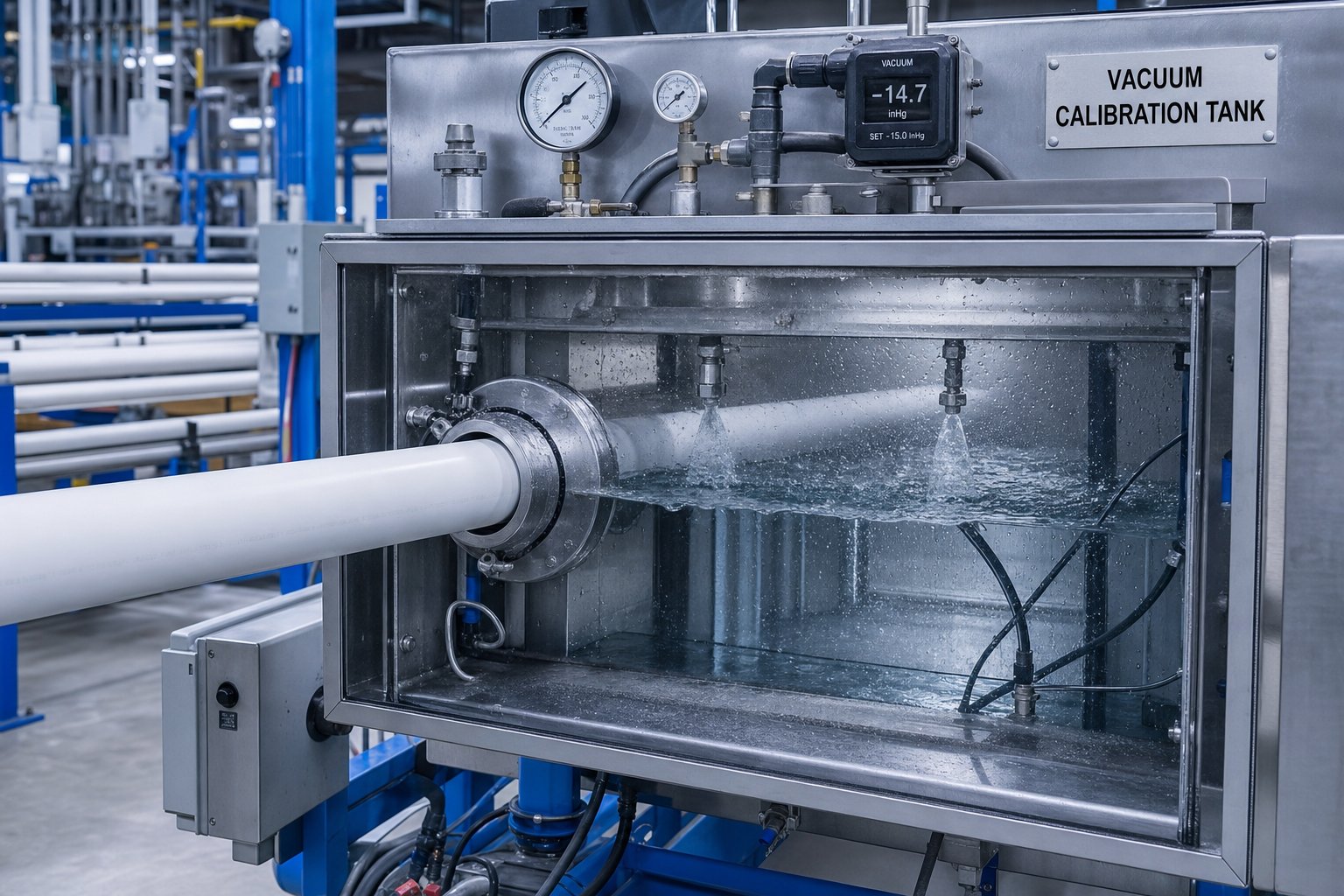
The moment extruded PVC exits the die, it begins to swell and sag under gravity. Without immediate intervention, you would end up with an amorphous blob rather than a precise cylinder. Vacuum calibration solves this by using external suction to pull the hot, pliable pipe wall outward against a rigid metal sleeve, locking the outer diameter to a controlled dimension before the material cools enough to hold its shape independently.
Here is the sequence: the hot extrudate enters a calibration sleeve — a precision-machined metal tube, typically brass or stainless steel — housed inside a sealed vacuum tank filled with cooling water. Vacuum applied to the tank's sealed chamber creates negative pressure around the pipe's exterior surface. This pressure differential forces the still-soft pipe wall outward against the sleeve's inner surface, setting the outer diameter with tight tolerances. Simultaneously, cooling water in the tank begins extracting heat from the pipe wall, progressively stiffening the PVC below its glass transition temperature so the calibrated dimensions become permanent.
Three variables govern calibration quality:
- Vacuum level — Too little vacuum and the pipe fails to contact the sleeve uniformly, producing undersized sections and ovality. Too much vacuum pulls the pipe surface into the sleeve's vacuum ports, creating raised bumps or drag marks on the outer surface. For PVC pipe, vacuum is typically maintained between 0.3 and 0.7 bar below atmospheric, adjusted based on pipe diameter and wall thickness.
- Water temperature — Cooling water inside the vacuum tank must be cold enough to stiffen the pipe's outer skin quickly but not so cold that it induces thermal shock. A sudden temperature drop creates uneven shrinkage between the rapidly cooling outer layer and the still-hot inner wall, building in residual stresses that cause warping or cracking downstream. Graduated cooling — starting warmer near the die entry and decreasing toward the tank exit — reduces this risk significantly.
- Sleeve design — The calibration sleeve's bore diameter directly determines the pipe's finished OD. Sleeve length, the number and placement of vacuum ports, and the water-cooling channel layout within the sleeve body all affect how uniformly the pipe contacts the sizing surface. Worn or damaged sleeves introduce ovality and surface defects that no amount of downstream adjustment can correct.
Pressure calibration — where internal air pressure pushes the pipe wall outward against a calibrating tube — exists as an alternative method but sees limited use in rigid PVC pipe production. Vacuum calibration dominates because it provides more consistent dimensional control across a wider range of pipe sizes and wall thicknesses, and it integrates naturally with the cooling tanks that follow.
Spray and Immersion Cooling Tanks
The vacuum calibration tank starts the cooling process, but it does not finish it. When pipe exits the calibrator, only the outer skin has stiffened. The inner wall and core of the pipe wall remain hot — potentially hot enough to soften the already-hardened outer layer through heat conduction if cooling is not continued. This is why every PVC pipe extrusion line includes extended cooling tanks downstream of the calibrator.
PVC's low thermal conductivity is the controlling factor here. Heat trapped in the pipe wall simply does not conduct outward quickly. Thick-walled pressure pipe — SDR 11 or SDR 17, for example — may need cooling tank lengths of 6 to 12 meters or more, depending on line speed and pipe diameter. The relationship is straightforward: thicker walls hold more heat, higher line speeds reduce contact time with cooling water, and both factors push cooling tank requirements longer.
Two cooling methods are common. Spray cooling uses precisely angled nozzles arranged around the pipe circumference inside a sealed tank. This approach eliminates the buoyancy problems that plague open-water immersion systems — where large-diameter pipes float against the top of the tank and cool unevenly on top versus bottom. Sealed spray tanks also allow better temperature gradient management, typically running inlet water at 40-55 °C and outlet water at 20-25 °C to avoid thermal shock.
Immersion cooling submerges the pipe in a water bath. It is simpler, less expensive, and easier to maintain — but introduces challenges. Temperature stratification between upper and lower water layers causes uneven cooling, and buoyancy forces acting on the pipe can cause deformation, making this method particularly unsuitable for large-diameter pipe. When immersion tanks are used, partitioning the tank into multiple sections with counter-flow water circulation — inlet at the last section, flowing opposite to the pipe direction — creates a cooling temperature gradient that reduces internal stress.
Regardless of the method, one rule holds: the pipe must reach near-ambient temperature before it contacts the haul-off unit. Any residual heat gradient remaining in the pipe wall at that point risks reheating the already-hardened outer surface, leading to deformation under the mechanical loads that follow.
Haul-Off, Cutting, and Downstream Finishing
The haul-off unit is the pacemaker of the entire downstream line. Its speed relative to the extruder's output rate directly controls pipe wall thickness — and by extension, whether the finished product meets or fails its dimensional specification.
Imagine two conveyor belts gently gripping opposite sides of the cooled pipe, pulling it forward at a constant, precisely controlled velocity. That is essentially what a caterpillar-type haul-off does. Multiple tracks — anywhere from two for small-diameter pipe to twelve for large-diameter products — distribute clamping force evenly around the pipe circumference using rubber or polyurethane pads. The haul-off speed must be steplessly adjustable and rock-steady. Speed instability directly causes diameter fluctuation, while any push-pull variation introduces surface waviness defects.
The critical relationship is this: slower haul-off speed relative to extruder output yields thicker pipe walls; faster speed stretches the material and produces thinner walls. This is not just a sizing tool — it is also a source of residual stress. Excessive haul-off speed orients PVC molecules in the extrusion direction, building in longitudinal stress that manifests as reversion (shrinkback) when the pipe is heated during installation or testing. The goal is to pull just fast enough to maintain dimensional targets without imparting unnecessary orientation.
Belt-type haul-offs serve a similar function but use flat belts rather than tracked pads, making them better suited for profile extrusion where non-circular cross-sections require conformable contact surfaces. For round PVC pipe, caterpillar-type units with contoured clamping blocks remain the standard because they distribute radial pressure more uniformly, reducing ovality risk.
Downstream of the haul-off, a series of finishing stations complete the transformation from extruded tube to saleable product:
Cutting systems must produce clean, square cuts without damaging the pipe or generating excessive dust. For PVC pipe from 63 mm to 630 mm, planetary saws are the standard — the cutter head orbits the pipe while a carbide-tipped blade feeds through the wall in a controlled arc. Blade feed rate relative to rotational speed is the critical parameter: too fast and the wall fractures ahead of the cut; too slow and frictional heat softens the PVC around the cut zone. Smaller-diameter pipes and thin-wall products benefit from chipless cutting systems that shear through the wall without generating dust or chips, eliminating the need for vacuum extraction.
Belling (socketing) machines heat one end of the cut pipe and expand it over a mandrel to form an integrated socket joint. Vacuum-type belling provides the highest dimensional precision and smooth socket finish, especially for medium and large-diameter PVC pipe. These machines can operate inline — automatically receiving cut pipe from the saw — or as standalone stations. Pipe diameters from 20 mm up to 800 mm are accommodated by different belling machine models, with vacuum belling dominating above 63 mm diameter and double-pipe belling improving throughput for smaller sizes.
Inline printing and marking systems apply product identification — pipe size, material grade, pressure rating, manufacturer code, production date, and applicable standard number — directly onto the pipe surface using inkjet or hot-stamp printers. This marking is not optional; standards compliance requires permanent, legible identification at regular intervals along the pipe length.
Stacking and bundling systems collect cut pipes, arrange them into bundles of specified count, and strap or wrap them for storage and transport. Automated stacking reduces manual handling labor and ensures consistent bundle geometry for efficient warehousing.
The complete downstream equipment sequence, from die exit to finished goods, follows this order:
- Vacuum calibration tank — sets outer diameter and begins cooling
- Spray or immersion cooling tanks — removes remaining heat from the pipe wall
- Haul-off unit — pulls the pipe at controlled speed to maintain dimensions
- Wall thickness and diameter measurement — ultrasonic or laser gauging for real-time quality verification
- Printer/marker — applies standards-compliant identification
- Planetary saw or chipless cutter — cuts pipe to specified length
- Belling machine (optional) — forms socket joints on pipe ends
- Stacking and bundling system — packages finished pipe for shipment
Each component in this chain interacts with the others. A cooling tank that removes heat inconsistently forces the haul-off to compensate for dimensional drift. Belt slip in the haul-off introduces length variation that the cutter cannot correct. The system behaves as a chain, and the weakest station determines overall line performance and product quality.
Even with every upstream and downstream system performing flawlessly, PVC pipe production generates defects — surface imperfections, dimensional drift, structural irregularities — that demand systematic diagnosis. Knowing which defect traces back to which cause, and which corrective action resolves it without creating new problems, is the troubleshooting discipline that separates reactive operators from proactive ones.
PVC Pipe Extrusion Defects with Root Causes and Corrective Actions
A defect on the production floor is never just a cosmetic problem. A rough outer surface, a wall that measures thin on one side, a yellowish tint creeping into what should be bright white pipe — each of these tells a specific story about what went wrong upstream. The challenge with PVC pipe extrusion troubleshooting is that causes overlap, symptoms mimic each other, and a hasty correction in one area can trigger a new problem somewhere else.
What follows is a systematic breakdown of the most common PVC extrusion defects, organized by category so operators and engineers can trace symptoms back to root causes and apply targeted corrections rather than chasing guesses.
Surface Defects and Their Root Causes
Surface quality is usually the first thing an operator notices — and the first thing a customer rejects. PVC pipe surfaces should be smooth, glossy, and free of visible imperfections on both the exterior and interior walls. When they are not, the cause almost always traces back to die conditions, compound fusion, or thermal degradation.
Shark-skinning (melt fracture at the die exit) appears as a fine, repetitive roughness or cracking pattern on the pipe's outer surface. The mechanism is straightforward: when the PVC melt passes through the die land at a shear rate exceeding its critical threshold, the surface layer tears cyclically as it alternates between sticking and slipping against the die wall. You will notice this defect worsen at higher extrusion speeds because increased output raises the volumetric flow rate through a fixed die gap, pushing shear stress higher.
Corrective actions target shear reduction at the die exit:
- Reduce screw speed or lower overall throughput to decrease volumetric flow rate through the die
- Increase die temperature to reduce melt viscosity, lowering the shear stress the surface layer experiences
- Polish die land surfaces to reduce friction at the polymer-metal interface
- Review the formulation's external lubricant level — insufficient metal-release lubricant intensifies stick-slip behavior at the die wall
Die lines — fine longitudinal grooves running the length of the pipe — are among the most common surface defects in both PVC pipe and extrusion profile PVC production. They originate from physical damage to the die land surface: scratches, nicks, or buildup of degraded material lodged in the die lip. A single carbon particle baked onto the die land acts like a plow, carving a continuous line into the pipe surface at extrusion speed. The fix is mechanical: regularly inspect, clean, and polish die and mandrel surfaces. Any design guideline for plastic extrusion tooling tubing will emphasize that die land finish quality directly transfers to product surface quality — there is no downstream process that erases what the die imprints.
Rough inner surfaces point to a different set of causes. Because the mandrel shapes the pipe's bore, damage or contamination on the mandrel surface produces internal lines and roughness that increase hydraulic friction and create stress concentration points. Beyond tooling condition, rough inner surfaces also result from inadequate compound fusion — if the PVC has not reached sufficient gelation before entering the die, the inner layer retains partially fused particle boundaries that produce a matte, grainy texture. Corrective measures include increasing barrel temperatures in the compression zone (gradually, to avoid degradation), verifying that processing aid levels are adequate to promote fusion, and inspecting the mandrel for accumulated deposits of degraded material.
Discoloration and yellowing is the visible signature of thermal degradation. When PVC exceeds its processing window — either through excessive barrel or die temperatures, prolonged residence time, or stagnation in dead spots — dehydrochlorination produces conjugated polyene sequences that shift the pipe color from white through yellow to brown. Even subtle yellowing signals that the compound's stabilizer capacity is being consumed faster than intended. Reducing temperature setpoints in the overheating zones, lowering screw speed to decrease frictional heat generation, and verifying that cooling system channels are clear and functional are the primary corrective actions. If discoloration appears specifically at startup or shutdown, the issue is likely extended residence time during transitions — a problem addressed through proper purging procedures and faster line stabilization protocols.
Dimensional and Structural Defects
Surface defects are visible. Dimensional defects are measurable — and often more dangerous because a pipe that looks perfect can still fail a pressure test or refuse to seal at a joint if its geometry is out of specification. These defects originate from interactions between die setup, process stability, and downstream equipment alignment.
Wall thickness variation (eccentricity) is arguably the most critical dimensional defect in PVC pipe production. A pipe with one side thick and the other thin has its pressure rating determined by the thinnest point — meaning the extra material on the thick side is wasted cost that adds weight without adding performance. The most frequent root cause is misalignment between the die and mandrel within the die head. Even fractions of a millimeter of off-center positioning create measurable thickness differences around the circumference. Uneven temperature distribution across the die head compounds the problem by causing the melt to flow faster on the hotter side, depositing more material there.
Ovality — the pipe being elliptical rather than circular — typically originates downstream rather than in the extruder. Insufficient vacuum pressure in the calibration tank fails to press the soft pipe uniformly against the sizing sleeve. Uneven spray patterns inside cooling tanks cause one side to shrink faster. Misalignment between the die centerline, calibration tank, and haul-off introduces asymmetric forces that pull the pipe out of round. Even inadequate roller support between stations — allowing still-warm pipe to sag under its own weight — can produce ovality that persists through cooling.
Voids and bubbles trapped within the pipe wall compromise structural integrity by creating internal stress concentrations. The most common source is moisture in the PVC compound. Residual water — from improperly dried filler, hygroscopic additives, or humid storage conditions — flashes to steam inside the barrel, generating gas pockets that become frozen into the pipe wall during cooling. Inadequate vacuum venting on the extruder barrel, excessive die temperatures that volatilize low-molecular-weight additives, or too much lubricant in the formulation can also produce gas entrapment.
Warping and bowing appear after the pipe has been cut — lengths that curve or twist rather than lying straight. The root cause is almost always residual stress locked into the pipe wall by uneven cooling or excessive haul-off tension. When the outer skin cools and stiffens while the inner wall remains hot, differential shrinkage creates stress gradients that manifest as curvature once the pipe is cut free from the line's mechanical constraint.
The table below provides a quick-reference diagnostic guide covering the most common PVC pipe defects, their primary causes, and corrective actions:
| Defect | Primary Cause(s) | Corrective Action(s) |
|---|---|---|
| Shark-skinning / melt fracture | Excessive die shear rate; insufficient external lubricant; low die temperature increasing melt viscosity | Reduce screw speed or throughput; increase die zone temperature; verify external lubricant loading; polish die land surfaces |
| Die lines (longitudinal grooves) | Scratches, nicks, or degraded material buildup on die land or mandrel surfaces | Clean, polish, or replace die and mandrel; implement scheduled die maintenance intervals |
| Wall thickness variation (eccentricity) | Die-mandrel misalignment; uneven die head temperature; inconsistent melt flow distribution | Re-center die and mandrel using adjustment bolts; verify all die head heating zones; check for flow obstructions in die channels |
| Ovality (out-of-round) | Insufficient or uneven vacuum in calibration tank; non-uniform cooling; haul-off or downstream equipment misalignment | Optimize vacuum level and verify spray nozzle uniformity; perform full centerline alignment of downstream equipment; ensure adequate pipe support between stations |
| Voids and bubbles | Moisture in PVC compound or filler; inadequate extruder degassing; volatile release from overheated additives | Dry compound and fillers to below 0.1% moisture; verify vacuum vent function; reduce melt temperature in overheating zones |
| Discoloration / yellowing | Thermal degradation from excessive temperature, prolonged residence time, or material stagnation in dead spots | Reduce barrel and die temperatures; lower screw speed; eliminate dead spots in die and adapter design; verify stabilizer loading and dispersion |
| Warping / bowing | Uneven cooling creating differential shrinkage; excessive haul-off speed inducing molecular orientation | Ensure uniform circumferential cooling; reduce haul-off speed to minimize orientation stress; verify water temperature consistency across cooling tanks |
| Rough inner surface | Mandrel surface damage or contamination; incomplete compound gelation; improper internal lubricant balance | Clean and polish mandrel; increase compression zone temperatures gradually; review processing aid and internal lubricant levels |
Process-Related Issues and Plate-Out
Some of the most persistent production problems in PVC pipe extrusion are not defects in the pipe itself — they are defects in the process that eventually cause pipe defects. Plate-out is the defining example, and it is almost exclusively a PVC-specific phenomenon.
Plate-out is the unwanted deposition of additives on metal surfaces — screws, barrel walls, die channels, and die lips — during processing. The residue appears in various forms: glassy or waxy films, brittle crystalline plaques, or in severe cases, blackened tar-like material baked onto surfaces. This buildup is not merely an annoyance. As plate-out accumulates on the die land, it narrows flow channels unevenly, creates drag marks on the pipe surface, and eventually flakes off as contamination particles embedded in the product. On screw surfaces, it disrupts conveying consistency and can act as an insulating layer that distorts the temperature profile.
The causes are multi-factorial, but three mechanisms dominate:
- Lubricant imbalance — Over-dosing external lubricant disrupts the polarity balance within the compound. The excess migrates toward metal surfaces, condenses, and crystallizes. Even a deviation of 0.1 phr beyond the optimal loading can shift the balance enough to initiate buildup. Conversely, insufficient internal lubricant raises melt viscosity, generating excessive frictional heat that degrades surface-layer PVC into sticky deposits.
- Poor stabilizer dispersion or outdated stabilizer chemistry — When stabilizer particles are not uniformly distributed throughout the dry-blend, localized zones of inadequate thermal protection degrade faster, producing acidic byproducts and metallic soap residues that deposit on metal surfaces. Legacy lead-based stabilizer systems are particularly prone to forming insoluble metallic chloride complexes that plate onto barrel and die walls. Modern calcium-zinc systems exhibit better solubility within the PVC matrix and can extend die-cleaning intervals significantly — from as little as 8 hours to 48 hours in some documented cases.
- High melt temperature — Excessive processing temperatures degrade PVC at the barrel wall and screw surface interface, producing carbonized deposits. Over-heated rear barrel zones — exceeding approximately 190 °C — can initiate degradation before fusion even begins, creating acidic byproducts that push stabilizer residues out of solution and onto metal surfaces.
The hidden cost of plate-out is substantial. A conservative estimate on a 300 kg/h production line suggests that 4% output loss to plate-out-related scrap can translate into tens of thousands of dollars annually — before accounting for the downtime required for screw pulls, die cleaning, and roll wipes that may interrupt every shift.
Burn marks represent a related but distinct problem. When die or adapter geometry creates dead spots — low-flow corners, sharp transitions, or poorly streamlined flow channels — PVC stagnates in those zones. Stationary material continues absorbing heat, eventually degrading into carbonized particles. When these particles finally dislodge, they travel through the die and embed in the pipe wall as black specks or streaks. The corrective approach is design-oriented rather than operational: proper screw and die engineering eliminates dead spots through streamlined flow paths, polished transitions, and geometries that maintain positive material movement across all channel surfaces. Retrofitting existing dies with flow-optimized inserts or replacing outdated tooling with modern streamlined designs addresses the root cause rather than just treating the symptom.
Effective PVC pipe extrusion troubleshooting follows a consistent discipline: observe the defect, trace it to the responsible process zone, verify the root cause through measurement rather than assumption, and apply the targeted correction. Resist the temptation to change multiple variables simultaneously — that approach might eliminate the immediate symptom but leaves you unable to identify which adjustment actually solved the problem, setting the stage for the same defect to return unpredictably.
Producing defect-free pipe, however, is only half the quality equation. Every pipe that leaves the line must also meet specific dimensional tolerances, pressure ratings, and material property requirements defined by industry standards — the external benchmarks that connect extrusion process control to real-world engineering specifications.
PVC Pipe Standards, Classifications, and Quality Testing
Here is a reality that many extrusion operators overlook: your barrel temperatures, die geometry, haul-off speed, and cooling parameters are not arbitrary choices. They exist to produce a pipe that meets a specific standard — a document that defines exact wall thickness tolerances, ovality limits, pressure ratings, and material properties. If the finished pipe fails those specifications, nothing else matters. The line ran perfectly, the surface looks flawless, but the product is scrap.
Understanding PVC pipe standards and specifications is not just quality-department work. It is extrusion-floor knowledge. Every die changeover, every calibration sleeve swap, and every haul-off speed adjustment traces back to a dimensional requirement specified in an ASTM or ISO document. Operators who understand these classifications make better process decisions — they know why specific tolerances exist and which parameters control them.
Schedule Ratings and SDR Classifications
Two fundamentally different systems define PVC pipe wall thickness, and confusing them is one of the most common specification errors in plastic pipe extrusion. Each system creates different relationships between pipe diameter, wall thickness, and pressure capacity — and each demands different extrusion setup parameters.
Schedule-based sizing — familiar as Schedule 40 and Schedule 80 — assigns wall thickness based on a fixed table that varies with nominal pipe diameter. A 2-inch Schedule 40 PVC pipe has a minimum wall thickness of 0.154 inches, while a 6-inch Schedule 40 pipe has a 0.280-inch wall. The wall gets progressively thicker at larger diameters, but the ratio of wall to diameter is not constant. This means the pressure rating actually decreases as diameter increases within the same schedule designation. Schedule 40 PVC at 1-inch has a higher working pressure than Schedule 40 at 8-inch because proportionally less material supports the internal pressure as the pipe gets bigger.
For extrusion operators, schedule-rated pipe means different die and calibration tooling for every diameter change — even within the same schedule class. The wall thickness jump from one nominal size to the next requires recalibrating haul-off speed relative to extruder output, adjusting cooling tank residence time to accommodate the different thermal mass, and verifying that the die gap produces the correct wall at the target line speed.
SDR (Standard Dimension Ratio) sizing takes a completely different approach. SDR expresses the ratio of a pipe's outside diameter to its minimum wall thickness as a single constant number. An SDR 26 pipe, for instance, always has an outside diameter that is 26 times its wall thickness — whether it is a 4-inch pipe or a 12-inch pipe. This geometric consistency produces a powerful result: two pipes of the same material and the same SDR have the same pressure rating regardless of their diameter, because the stress distribution in the pipe wall remains proportionally identical.
The relationship between SDR number and performance follows an inverse rule that you should commit to memory: a lower SDR means a thicker wall relative to diameter, which yields higher pressure capacity. SDR 17 PVC pipe is rated at 250 psi, while SDR 26 is rated at 160 psi, and SDR 41 drops to 100 psi. Each step up in SDR number represents approximately 20% less wall material.
From an extrusion standpoint, SDR-based pipe simplifies some decisions. Because the wall-to-diameter ratio stays constant, the proportional relationship between extruder output, haul-off speed, and die gap follows a consistent pattern across diameters. However, absolute cooling requirements still scale with pipe size because the physical wall thickness increases with diameter even though the ratio remains fixed.
One critical distinction separates SDR from DR. Standard SDR values follow the ANSI preferred number series — 9, 11, 13.5, 17, 21, 26, and 32.5 — with each step representing a standardized wall reduction. DR (Dimension Ratio) uses the same formula but applies to any ratio, including non-standard values like DR 14, DR 18, and DR 25 found in AWWA C900 municipal water pipe specifications. In practice, many professionals use the terms interchangeably, but specification documents require precision.
Key ASTM and ISO Standards for PVC Pipe
Every PVC pipe extrusion line operates under the requirements of at least one — and usually several — governing standards. These documents specify not just dimensions but material cell classifications, hydrostatic design bases, marking requirements, and test methods that the production process must consistently satisfy. The most relevant standards for rigid PVC pipe include:
- ASTM D1785 — covers PVC pressure pipe in Schedules 40, 80, and 120 using iron pipe size (IPS) outside diameters. This standard specifies minimum wall thickness, outside diameter tolerances, and pressure ratings for water distribution, irrigation, and industrial piping systems. It is the foundational standard for schedule-rated PVC pipe in North America.
- ASTM D2241 — covers SDR-rated PVC pressure pipe using IPS outside diameters. Pressure classes range from 63 psi (SDR 64) through 315 psi (SDR 13.5), providing engineers a full spectrum of options for applications from low-pressure irrigation to high-pressure water transmission.
- ASTM D3034 — specifies PVC sewer pipe for non-pressure gravity drainage applications. This standard uses SDR 35 and SDR 26 classifications with different joint configurations (elastomeric gasket joints) and focuses on ring stiffness and chemical resistance rather than pressure capacity.
- ASTM F441 — covers CPVC (chlorinated PVC) pipe in Schedules 40 and 80. CPVC extends the usable temperature range to approximately 200 °F (93 °C), making it suitable for hot-water distribution where standard PVC — limited to 140 °F (60 °C) — cannot perform. CPVC pipe extrusion requires modified temperature profiles and stabilizer systems compared to standard PVC, though the same twin-screw equipment platform is typically used.
- ISO 1452 — the international standard for PVC-U (unplasticized PVC) pressure pipe systems intended for water supply and general purposes. This standard series covers pipe, fittings, and system design using metric sizing and operates under different dimension ratio designations than the ASTM system, making it essential knowledge for manufacturers serving export markets.
Each of these standards defines tolerances that the extrusion line must hold continuously — not just on sample pieces pulled for inspection. Minimum wall thickness means exactly that: no point on the pipe circumference can measure below the specified value. Ovality limits define how far from perfectly round the pipe cross-section may deviate. Outside diameter must fall within a specified plus/minus tolerance band. Meeting these requirements hour after hour, shift after shift, demands the combination of proper equipment setup, stable process control, and systematic quality verification.
Quality Testing and Compliance on the Extrusion Line
Producing pipe that meets standards is one thing. Proving it meets standards — consistently, with documented evidence — is another. Quality testing in PVC pipe production spans both inline measurements that provide real-time feedback and offline tests that verify mechanical performance against specification requirements.
Inline measurements happen continuously during production, providing immediate data that operators use to correct process drift before it produces non-conforming product:
- Ultrasonic wall thickness measurement — Non-contact sensors mounted downstream of the cooling tanks measure wall thickness at multiple points around the pipe circumference using ultrasonic pulse-echo technology. These systems detect eccentricity, thin spots, and gradual drift in real time, typically displaying readings on a continuous chart that shows wall thickness variation across the full production run. Any deviation beyond the standard's tolerance triggers an alarm for operator intervention.
- Laser or optical diameter gauging — Shadow-measurement or laser scanning systems verify that outside diameter remains within specification. These units also calculate ovality by comparing diameter readings taken at different angular positions around the pipe.
Offline testing validates mechanical properties and long-term performance characteristics that cannot be measured during production:
- Hydrostatic burst testing — Pipe samples are filled with water, sealed, and subjected to internal pressure until failure. This test determines resistance to constant internal pressure at specified temperatures, verifying that the pipe's actual burst strength exceeds the design safety margin required by the applicable standard. Short-term burst tests (ASTM D1599) apply rapidly increasing pressure, while long-term tests (ASTM D1598) sustain constant pressure for extended periods to evaluate creep behavior.
- Flattening tests — A section of pipe is compressed between flat plates until the pipe walls contact each other. The test evaluates whether the pipe cracks, splits, or delaminates under this severe deformation — a direct indicator of gelation quality. Pipe with incomplete fusion fails flattening tests at relatively low deflections because poorly bonded primary-particle boundaries propagate cracks under bending stress.
- Drop-weight impact testing — A weighted striker (tup) is dropped onto pipe samples at controlled temperatures to assess impact resistance. This test is particularly sensitive to gelation level and compound formulation — under-fused pipe or pipe with insufficient impact modifier will exhibit brittle fracture patterns rather than ductile deformation. Standards specify the minimum percentage of samples that must survive the drop test without cracking.
- Reversion (shrinkback) testing — Cut pipe samples are placed in an oven at elevated temperature (typically 150 °C for PVC) and measured for longitudinal shrinkage. Excessive shrinkage indicates that the extrusion process imparted too much molecular orientation — usually from excessive haul-off speed or insufficient relaxation time between die exit and cooling. Standards limit allowable reversion to ensure that pipes will not shrink significantly during service or installation, which could compromise joint integrity.
- Ring stiffness testing — Measures the pipe's resistance to deflection under external load, which is critical for buried gravity sewer applications. The test applies a compressive load to a short pipe ring section and measures force versus deflection to calculate stiffness values that must meet or exceed the minimum specified by standards like ASTM D3034.
You will notice a pattern across all of these tests: they do not just verify dimensions — they verify that the extrusion process produced the correct internal structure. Hydrostatic strength depends on gelation quality and wall integrity. Impact resistance reflects both compound formulation and fusion completeness. Reversion reveals process-induced stress from haul-off and cooling conditions. This is why experienced quality engineers treat test failures not as isolated product problems but as process diagnostic signals — each failed test points backward toward a specific extrusion parameter that drifted outside its optimal range.
Meeting PVC pipe standards and specifications is ultimately a systems challenge. The compound must be correctly formulated, the extruder must achieve proper gelation without degradation, the die must distribute flow uniformly, and the downstream equipment must hold dimensions while minimizing residual stress. When all of these elements align, the testing simply confirms what the process already delivered. When they do not, testing catches what process drift allowed through — and the corrective action loop begins again.
Standards define what the pipe must be. Process optimization determines whether you can produce it efficiently enough to remain competitive — hitting those specifications while minimizing energy consumption, material waste, and unplanned downtime.
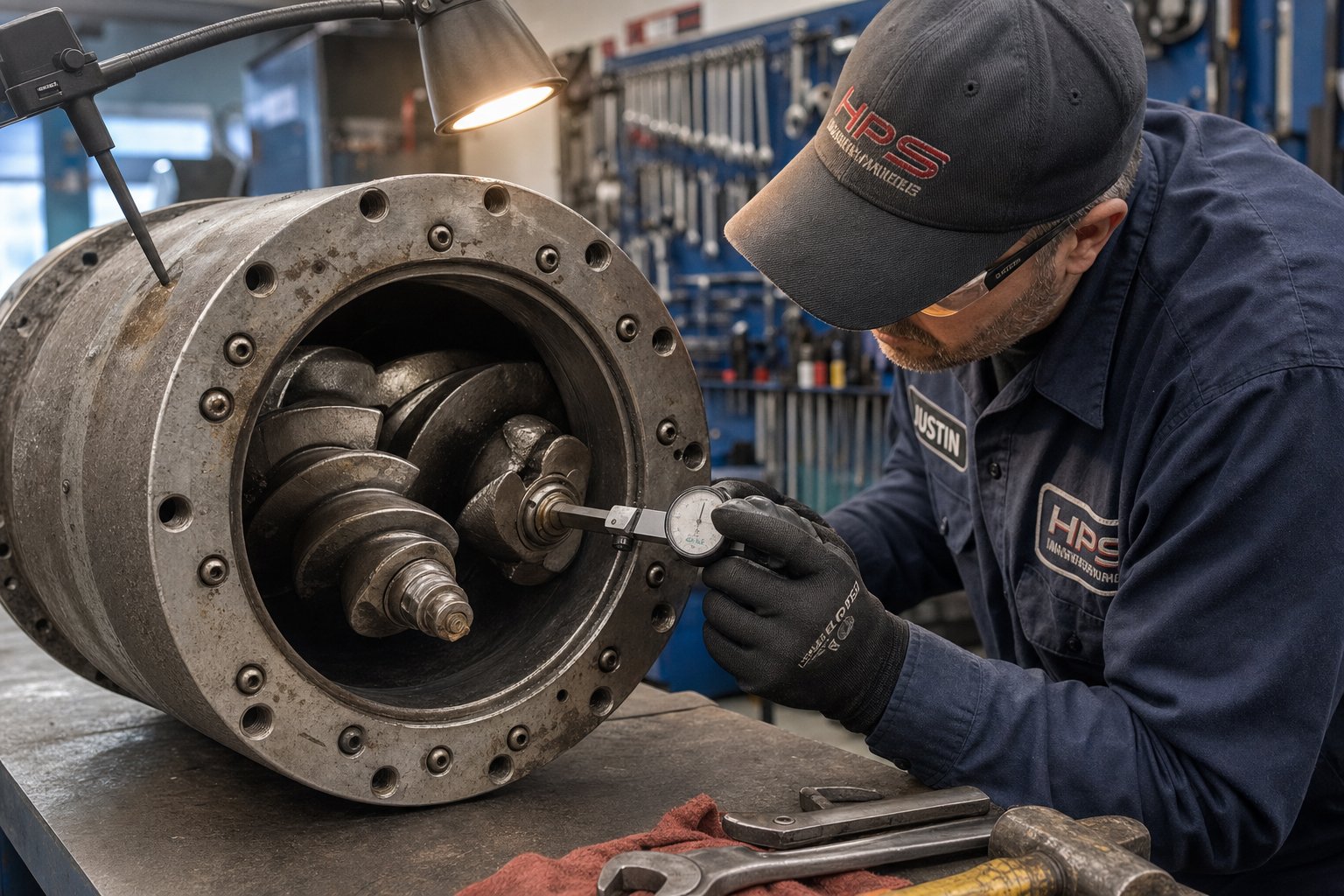
Optimizing Line Efficiency and Long-Term Extrusion Performance
Producing specification-compliant PVC pipe is the baseline. Producing it efficiently — with minimal energy waste, near-zero scrap, and equipment that maintains consistent performance month after month — is what separates profitable operations from those bleeding margin through invisible losses. Energy costs, material waste, and progressive equipment wear erode profitability quietly, and they compound over time. A worn screw-barrel assembly consuming 12% more specific energy while producing 8% more off-spec pipe does not announce itself with alarms. It shows up in quarterly cost reports, by which point the losses have already accumulated.
This final section addresses the operational and economic levers that PVC extruders can pull to maximize line performance over the long term — areas that most process guides ignore entirely.
Energy Efficiency and Throughput Optimization
Energy consumption in PVC pipe extrusion is dominated by the extruder drive motor. The plasticizing process — converting dry-blend powder into a uniformly fused melt — accounts for roughly 80% of total line energy use. Every kilowatt-hour that goes into unnecessary frictional heat, excessive melt temperature, or compensating for worn components is energy that adds cost without adding value.
The key metric here is specific energy consumption (SEC), expressed in kWh per kilogram of output. SEC gives you a normalized measure of how efficiently your extruder converts electrical energy into useful plasticizing work, independent of throughput rate. A well-optimized conical twin-screw PVC pipe line typically operates at a significantly lower SEC than a comparable single-screw setup because the positive-displacement conveying mechanism wastes less energy fighting PVC's wall-slip behavior.
Screw speed plays a nuanced role. The intuitive assumption — that running faster always improves efficiency — does not hold for PVC. Research by Bovo et al. demonstrated that specific energy consumption in PVC extrusion does not follow a simple downward trend with increasing screw speed. Instead, SEC reaches a minimum at a moderate speed — around 50 rpm in the tested compounds — after which energy consumption can actually increase due to wall-slip effects disrupting the expected relationship between screw speed and flow rate. Compounds with high calcium carbonate filler content showed the most pronounced slip behavior, making this finding directly relevant to rigid PVC pipe formulations loaded with CaCO3.
Material properties also drive energy demand in ways that formulation engineers can influence. Harder PVC compounds required up to 60% more energy to extrude compared to softer ones, and higher-viscosity formulations within the same hardness class demanded 20% more energy than lower-viscosity alternatives. These findings suggest that compound optimization — selecting resin grades, plasticizer levels, and filler loadings that minimize viscosity at processing temperatures — can deliver substantial energy savings without changing equipment.
Properly matched screw and barrel geometry reduces energy waste by converting more mechanical energy into useful plasticizing work rather than surplus heat that barrel cooling must then remove. When the screw profile matches the compound's fusion characteristics, material reaches target gelation at the correct barrel position without excessive shear input. An oversized screw for the throughput requirement generates unnecessary frictional heat. An undersized one forces higher RPM, pushing SEC upward and narrowing the already tight processing window.
Progressive screw and barrel wear introduces a creeping energy penalty that many operators fail to connect to their utility bills. As flight clearance increases from wear, material leaks backward over the screw flights rather than conveying forward. To maintain the same output rate, operators increase screw speed — which increases frictional heat generation, raises discharge temperature, and forces the cooling system to work harder. The result is higher energy input for the same throughput, often accompanied by degraded product quality from the elevated melt temperature. In one documented example, a 100-mm extruder with worn flights required progressively higher screw speeds to maintain 150 kg/hr output, with discharge temperature climbing from 236 °C to nearly 246 °C — a temperature too high for stable PVC processing.
Material Waste Reduction and Regrind Strategy
Material waste in PVC pipe extrusion concentrates in two areas: startup and shutdown transitions, and in-process scrap from dimensional or quality deviations. Both are controllable — but PVC's thermal sensitivity makes the strategies different from those used with polyolefins.
Startup and shutdown procedures for PVC demand special attention because the polymer cannot tolerate extended residence at processing temperatures. Unlike polyethylene, which can remain in the barrel for extended periods without catastrophic degradation, PVC and other chlorine-containing polymers must be fully purged before shutdown or they will rapidly decompose, forming carbonized residue and releasing corrosive HCl gas that attacks barrel and screw surfaces. Leaving PVC compound in a hot barrel overnight virtually guarantees a contaminated startup the next morning — with carbon specks, discolored material, and potentially damaged barrel linings.
The recommended approach involves purging the barrel completely with a thermally stable purge compound — typically a polyolefin-based material — before shutting down heaters. On startup, the purge compound is displaced with fresh PVC compound at controlled temperatures, minimizing both material waste and the risk of degradation-related contamination. A few practical details make a meaningful difference:
- Purge at production output rate, not at low speed. Low-speed purging reduces shear stress near metal surfaces — the very forces needed to clean material from barrel walls, screw flights, and downstream components. Material left behind at low-speed purging shows up as contamination once the line reaches production rates.
- Lower barrel temperatures slightly during purging to increase purge compound viscosity, which enhances wall-cleaning effectiveness. However, keep die and adapter temperatures at normal levels so the stiffer purge can flow through and clean downstream surfaces.
- Use purge compounds with similar viscosity to the PVC compound being displaced. A much stiffer purge cleans well but is difficult to displace afterward. A much softer purge flows easily but lacks the mechanical scrubbing action needed to remove PVC deposits.
Regrind strategy for PVC pipe requires careful management of the material's finite thermal stability. Every extrusion pass consumes stabilizer capacity and adds heat history. Regrind — reprocessed pipe from startup scrap, cut-offs, or rejected product — has already used a portion of its stability budget. Blending it back into virgin compound at excessive ratios pushes the overall thermal budget toward the degradation boundary.
Industry practice typically limits regrind addition to 5-10% of the total feed blend for pressure-rated pipe, where mechanical properties and long-term hydrostatic performance are critical. Non-pressure applications like drainage and sewer pipe may tolerate higher ratios, sometimes up to 20%, depending on the regrind's heat history and the standards being targeted. Regrind quality matters as much as quantity — material that experienced significant degradation during its first pass (visible as yellowing or reduced impact strength) should be segregated and diverted to lower-specification products rather than blended into pressure pipe production.
Process-driven scrap reduction delivers the highest return because it eliminates waste at the source. Tighter process control — stable melt pressure, consistent haul-off speed, calibrated temperature profiles — directly reduces the frequency and duration of out-of-spec production. Operator training plays an equally important role. An experienced operator who recognizes the early signs of process drift — a subtle torque shift, a 2 °C melt temperature creep, a slight change in pipe surface gloss — can intervene before the deviation produces scrap. Investing in operator skill development often yields faster payback than capital equipment upgrades.
Maintaining Consistent Plasticizing Performance Over Time
The screw and barrel assembly is the heart of any extrusion line. Its condition at any given moment directly determines output rate, dimensional consistency, gelation quality, and energy efficiency. A new, properly specified screw-barrel system delivers peak performance on day one. The question is: how long does that performance last, and what can you do to extend it?
Wear in PVC extrusion progresses through a predictable pattern. CaCO3 filler particles grind against screw flight tips and barrel bore surfaces, gradually increasing the clearance between them. Simultaneously, HCl gas released during normal processing attacks metal surfaces through chemical corrosion, weakening the very layers designed to resist abrasive wear. The combination is uniquely aggressive — neither purely abrasive nor purely corrosive, but a synergistic attack that standard carbon-steel components cannot withstand.
The performance consequences of this wear are measurable long before they become visually obvious. As flight clearance increases, conveying efficiency drops — material leaks backward over worn flights instead of moving forward. To compensate, operators increase screw speed, which raises frictional heat, elevates discharge temperature, and narrows the processing window. Specific rate — the output per unit of screw speed — declines steadily. Eventually, the line cannot maintain target throughput at acceptable melt temperatures, and production rate must be cut. For critical-duty applications, screws should be replaced when flight clearance reaches approximately twice the original specification. Noncritical products can tolerate more wear, but the economic penalty of reduced output and higher energy consumption still accumulates.
Preventive maintenance schedules should include regular clearance measurements taken during planned shutdowns. The procedure is straightforward: pull the screw, measure flight-tip diameters at multiple points along the length, and compare against original specifications. Barrel bore diameter is measured with an inside micrometer or bore gauge at corresponding positions. Documenting these measurements over time creates a wear trend that allows you to predict when replacement will be necessary — rather than discovering it through a product quality crisis.
A practical guideline for measurement intervals: check flight clearance every 2,000-4,000 operating hours, depending on filler loading and compound abrasiveness. Lines running high-CaCO3 formulations — 15 phr and above — should lean toward the shorter interval. Keep a spare screw in storage so replacement can happen during a scheduled shutdown rather than forcing an emergency line stop. One important caveat from industry experience: a screw should never be refurbished more than three times, because repeated welding of hardfacing onto the base metal degrades the substrate, increasing the risk of delamination during operation.
Barrel lifespan follows a different curve. Iron-based bimetallic barrel liners typically last approximately three times the service life of a screw, thanks to the larger surface area distributing wear across a broader zone. However, PVC's corrosive HCl gas can accelerate barrel wear disproportionately if the bimetallic liner's alloy composition is not matched to the application. Standard nitrided barrels offer minimal protection in PVC service — the corrosive environment rapidly breaches the nitrided layer, exposing the base steel beneath.
The decision between refurbishment and replacement comes down to economics and metallurgy. A worn screw with intact base metal can be rebuilt with new hardfacing for a fraction of the cost of a new unit. A barrel with a breached bimetallic liner, however, cannot be reliably re-lined — replacement is typically the only option. When that replacement decision arrives, the metallurgical specification of the new barrel becomes the most consequential choice you will make for the next several years of production.
Manufacturers sourcing replacement conical twin screw barrels should prioritize suppliers who engineer specifically for PVC applications — where the dual demands of HCl corrosion resistance and CaCO3 abrasion resistance impose metallurgical requirements that general-purpose barrel suppliers often cannot meet. NANHAIYA's conical twin screw barrel solutions are purpose-built for PVC pipe, profile, sheet, and WPC extrusion manufacturers who need drop-in replacement barrels engineered for wear resistance and consistent plasticizing output. Their application-matched metallurgical specifications address the specific corrosion-abrasion profile of CaCO3-filled PVC compounds, helping restore — and in some cases improve upon — the original equipment's plasticizing consistency and dimensional stability.
Regardless of supplier choice, the principle remains the same: a PVC pipe extrusion line's long-term profitability is determined not just by how well it runs on day one, but by how consistently it maintains that performance across thousands of operating hours. Energy optimization, disciplined waste management, and proactive screw-barrel maintenance are not glamorous topics — but they are the operational foundations that separate high-margin PVC pipe operations from those that gradually lose ground to rising costs and declining output quality.
Frequently Asked Questions About PVC Pipe Extrusion
1. Why does PVC pipe extrusion require a twin-screw extruder instead of a single-screw?
PVC dry-blend powder has low bulk density and exhibits wall-slip behavior, meaning it slides against metal rather than gripping it. Single-screw extruders rely on barrel-wall friction to convey material forward, which PVC undermines. Conical counter-rotating twin-screw extruders use intermeshing, positive-displacement screw geometry to force material forward regardless of friction. Their large conical feed opening accepts fluffy powder without bridging, while the tapering barrel progressively compresses the compound and delivers controlled low shear — essential for staying within PVC's narrow 170-210 degrees C processing window. This is why virtually all rigid PVC pipe plants standardize on conical twin-screw systems.
2. What is the ideal gelation level for PVC pipe and why does it matter?
Optimal gelation for PVC pipe typically falls between 60% and 80%. Gelation refers to the progressive fusion of PVC primary particles under heat and shear — not true melting. Below 60%, particle boundaries remain poorly bonded, resulting in weak impact strength and susceptibility to crack propagation under pressure. Above 80%, the compound approaches over-fusion, consuming its finite thermal stability budget and risking dehydrochlorination — the release of corrosive HCl gas that triggers autocatalytic degradation. Achieving the sweet spot depends on resin K-value, stabilizer system, lubricant balance, barrel zone temperatures, and screw shear input working together as a coordinated system.
3. What causes plate-out in PVC extrusion and how can it be prevented?
Plate-out is the buildup of additive residues — waxy films, crystalline plaques, or carbonized deposits — on screws, barrel walls, and die surfaces during PVC processing. The three primary causes are lubricant imbalance (especially excess external lubricant migrating to metal surfaces), poor stabilizer dispersion creating localized degradation zones, and excessively high melt temperatures that decompose PVC at the barrel-metal interface. Prevention starts with precise formulation control — keeping external lubricant within the optimal phr range, ensuring thorough dry-blend mixing for uniform stabilizer distribution, and maintaining barrel temperatures below the degradation threshold. Switching from legacy lead-based stabilizers to modern calcium-zinc systems can also extend die-cleaning intervals significantly.
4. What is the difference between Schedule and SDR ratings for PVC pipe?
Schedule ratings (such as Schedule 40 and Schedule 80) assign a fixed wall thickness to each nominal pipe diameter based on a lookup table. Because the wall-to-diameter ratio is not constant, the actual pressure rating decreases as pipe diameter increases within the same schedule. SDR (Standard Dimension Ratio) takes the opposite approach — it maintains a constant ratio of outside diameter to wall thickness across all pipe sizes. An SDR 26 pipe always has an OD that is 26 times its wall thickness regardless of diameter, so all SDR 26 pipes of the same material share the same pressure rating. For extrusion operators, SDR-based pipe simplifies die gap and haul-off relationships across sizes, while schedule-rated pipe requires unique tooling setups for every diameter change.
5. How often should conical twin-screw barrels be inspected and when should they be replaced?
Flight clearance measurements should be taken every 2,000 to 4,000 operating hours, with lines running high-CaCO3 formulations (15 phr and above) leaning toward the shorter interval. Replacement is recommended when flight clearance reaches approximately twice the original specification for critical-duty products like pressure pipe. PVC compounds impose a dual wear mechanism — abrasive CaCO3 filler grinds against screw flights while corrosive HCl gas attacks metal surfaces — making application-specific barrel metallurgy essential. Suppliers like NANHAIYA engineer conical twin screw barrels specifically for PVC pipe, profile, sheet, and WPC extrusion, matching bimetallic liner alloy composition to this corrosion-abrasion profile for extended service life and consistent plasticizing output.
Written by
Nanhaiya Technical Team
Zhoushan Nanhaiya Plastic Machinery Co., Ltd.
The Nanhaiya technical team supports screw and barrel manufacturing projects through application review, technical communication, custom manufacturing coordination, and production and quality control.
Discuss Your Application
Related Articles
More insights on screw barrel technology and plastics processing.

Extruder Machine Decoded: From Raw Pellet To Finished Product
Oct 6, 2026
Learn how an extruder machine works, compare single-screw vs. twin-screw types, and get expert guidance on specs, troubleshooting, and selection.
Read Article
PE Pipe Making Machine Decoded: From Raw Resin to Flawless Pipe
Oct 4, 2026
Learn how a PE pipe making machine works, from resin to finished pipe. Covers components, material grades, automation, troubleshooting, and buyer selection tips.
Read Article
PVC Profile Making Machine Decoded: From Raw Resin To Profit
Oct 3, 2026
Learn how a PVC profile making machine works — extrusion process steps, key technical parameters, die design, calibration methods, maintenance, and total cost of ownership.
Read ArticleLooking for something else?
Search by material, symptom or product and jump straight to the relevant page.
These are navigation suggestions based on keyword matching — not a quotation, not a delivery commitment, and not a substitute for engineering review. Final specification is confirmed by our engineers against your drawings and processed material.
Need help with screw barrel selection?
Share your machine model, processed material and application. Our team can help with pricing and technical support.