

Why PVC Extrusion Troubleshooting Requires a Different Approach
Imagine you're running a PVC pipe line and a surface defect suddenly appears. Your instinct might be to bump up a barrel zone temperature or dial back screw speed. But if you're treating PVC the same way you'd treat polyethylene or polypropylene, you're likely making the problem worse. PVC extrusion troubleshooting is not a guessing game of random parameter adjustments — it's a systematic diagnostic discipline that traces defects back to their true root causes across formulation, machine settings, screw mechanics, and downstream equipment.
What makes this material so demanding? PVC operates within an extremely narrow processing window where the difference between under-fusion and thermal degradation can be as slim as a few degrees. Unlike polyolefins that simply melt and flow, PVC undergoes a complex fusion and gelation process where primary particles must physically break down and interdiffuse to form a strong, homogeneous structure. Get it wrong, and you'll see fish eyes, rough surfaces, yellowing, or catastrophic HCl release. That thermal sensitivity is exactly why generic plastic extrusion advice falls short here.
This guide is built specifically for PVC processors — operators, technicians, and process engineers who need answers rooted in PVC science, not recycled polyolefin tips. You can jump directly to a specific defect symptom for a quick fix, or read sequentially for a comprehensive understanding of how each process variable connects to the next.
Why PVC Demands Specialized Troubleshooting
PVC's thermal degradation risk sets it apart from virtually every other commodity thermoplastic. The polymer begins releasing hydrogen chloride (HCl) gas at temperatures dangerously close to its processing range, which is why every viable PVC compound relies on heat stabilizers to extend the safe processing window. Lubricants — both internal and external — play equally critical roles, controlling melt viscosity and preventing the compound from sticking to metal surfaces. Without the right stabilizer-lubricant balance, no amount of machine adjustment will produce acceptable output.
Consider the differences highlighted in a comparison of PVC and polyolefin extrusion: PVC is typically processed as a dry blend on double screw extruders, while PE and PP use granular feedstock on single screw machines. PVC requires roughly one-third the specific drive energy of polyolefins, yet it demands far more precision in thermal management. Under extrusion conditions, PVC behaves more like a rubber-like solid forming crystallites and tie molecules — not a free-flowing melt like PE. These fundamental differences mean that troubleshooting strategies proven on polyolefin lines simply do not translate to PVC.
How This Guide Is Organized
Every section ahead targets a specific dimension of the diagnostic process. Here's your roadmap for quick navigation:
- The First Five Minutes — A rapid five-check diagnostic protocol to run before adjusting anything
- Zone-by-Zone Barrel Temperature Troubleshooting — Systematic thermal diagnostics from feed zone through die
- PVC Fusion and Gelation Defect Diagnosis — Understanding under-fusion vs. over-fusion and how to correct each
- Surface Defect Differential Diagnosis — Distinguishing similar-looking defects with entirely different root causes
- Formulation Root Causes — Identifying when the compound recipe, not the machine, is driving the defect
- Screw Design Impact — How screw geometry and wear create problems that parameter changes cannot solve
- Seasonal and Environmental Factors — Why processes shift with ambient temperature and humidity
- Preventive Maintenance Protocols — Structured routines that eliminate recurring defects before they start
Whether you're chasing a persistent surface roughness issue or trying to understand why last winter's settings no longer work in summer, the answers lie in matching the right diagnostic method to PVC's unique processing behavior. And that process starts — literally — in the first five minutes after a defect appears.
The First Five Minutes When a Defect Appears
A defect just showed up on the line. Maybe it's a rough patch on the extrudate surface, maybe it's a sudden wall thickness drift, or maybe the motor load just spiked without explanation. What you do in the next five minutes determines whether you solve the problem in thirty minutes — or spend the rest of the shift chasing your own adjustments.
Most extrusion troubleshooting cycles fail not because operators lack knowledge, but because too many variables change at once before the problem is even classified. A structured starting protocol eliminates that trap entirely. The following five-check sequence gives you a repeatable diagnostic framework that narrows the problem domain before a single parameter gets touched.
The Five Initial Checks Every Operator Should Perform
When a PVC extrusion defect appears, resist the urge to reach for the temperature controller. Instead, run through this PVC extrusion defect diagnostic checklist in order — each check builds on the last and points you toward the right section of this guide for deeper analysis.
- Visual inspection of the extrudate and die exit. Walk to the die and examine the product as it emerges. Is the defect already visible at the die lip, or does it develop further downstream during sizing, cooling, or haul-off? This single observation splits your entire diagnostic path in two. Defects present at the die exit point to melt quality, barrel conditions, or formulation issues. Defects that appear only downstream point to calibration, cooling, or mechanical alignment problems. Look for surface texture changes, discoloration, dimensional irregularities, or any visible pattern in the defect — intermittent versus continuous, one-sided versus uniform.
- Melt pressure and melt temperature readings at the adapter. Check your pressure transducer and melt thermocouple readings at the adapter or die entry. Compare them to your documented baseline. A rising melt pressure with stable screw speed suggests a flow restriction — possibly screen pack loading, die buildup, or increased melt viscosity from a formulation shift. Dropping pressure may indicate screw wear, feed inconsistency, or a material change. Melt temperature deviations reveal whether the barrel profile has drifted or whether shear-generated heat has changed. For PVC extruder melt pressure troubleshooting, even small deviations of 5-10% from baseline deserve attention because PVC's narrow processing window amplifies the downstream effects.
- Motor amperage or torque reading relative to baseline. Your drive motor is a real-time sensor for what's happening inside the barrel. Elevated amps at the same screw speed indicate higher melt viscosity — possibly from under-temperature conditions, a lubricant imbalance, or a material batch change. Reduced amps might signal over-temperature conditions, reduced feed rate, or advanced screw wear reducing compression effectiveness. Compare the current reading against your recorded baseline for the same product and screw speed. If you don't have a baseline, this is exactly why you'll want to build one (covered in the preventive maintenance section later).
- Hopper feed consistency and raw material verification. Look into the hopper. Is the dry blend or compound flowing freely and consistently, or do you see bridging, rat-holing, or irregular feed behavior? Confirm the material in the hopper matches what should be running — wrong resin lot, contaminated regrind, or an incorrect additive batch can produce defects that perfectly mimic machine-related problems. If a material batch change occurred recently, the formulation becomes the prime suspect regardless of what the machine settings show.
- Downstream equipment alignment and vacuum/water checks. Inspect the calibration tank, vacuum levels, cooling water temperature, haul-off belt condition, and cutter alignment. A shifted calibration sleeve, a vacuum leak, inconsistent water flow, or a worn haul-off belt can all introduce defects that look like extruder problems but originate entirely downstream. Verify that nothing was bumped, adjusted, or disrupted since the last good production run.
This entire sequence takes about five minutes. It costs nothing. And it prevents the single most expensive mistake in PVC processing — changing a parameter before you know which part of the line introduced the defect.
Reading the Symptoms Before Touching the Controls
Here's a scenario every experienced operator recognizes: a surface defect appears, someone increases die temperature by 5°C, the defect changes slightly, so they also bump barrel zone three, then adjust screw speed to compensate for the output shift, and within twenty minutes the line is running three variables away from its proven baseline — with the original defect still present plus two new ones layered on top.
PVC compounds are uniquely unforgiving of this approach. Because formulation variables — stabilizer levels, lubricant balance, filler loading — interact directly with processing variables like temperature, shear, and residence time, changing multiple settings simultaneously makes root cause isolation nearly impossible. A temperature increase might mask a lubricant deficiency temporarily, while the underlying imbalance continues to worsen.
The disciplined approach starts with documentation. Before making any adjustment, record your current baseline conditions:
| Parameter | What to Record | Why It Matters |
|---|---|---|
| Melt temperature | Actual reading at adapter or die entry | Reveals thermal drift independent of set points |
| Zone temperatures | All barrel zone set points and actual readings | Identifies heater or thermocouple malfunctions |
| Screw speed (RPM) | Current operating speed | Baseline for shear and output rate |
| Melt pressure | Adapter or die entry pressure reading | Detects flow restrictions or feed issues |
| Motor amps/torque | Drive load percentage or amperage | Proxy for melt viscosity and screw condition |
| Line speed | Haul-off speed setting and actual speed | Required for dimensional troubleshooting |
| Defect description | Location, timing pattern, visual appearance | Prevents diagnosis from memory, which is unreliable |
With this snapshot in hand, apply the one-variable-at-a-time methodology. Make a single, deliberate change — one temperature zone, or screw speed, or a downstream setting — then allow the line sufficient time to stabilize before evaluating the result. For PVC extrusion, stabilization typically requires at least three to five minutes of steady-state operation after a thermal change, since PVC's high melt viscosity means temperature shifts propagate slowly through the barrel.
Always record, then observe, then change one variable, then observe again. This is the only reliable path to root cause isolation in PVC extrusion troubleshooting.
This principle sounds simple, but it demands discipline — especially under production pressure when scrap is accumulating and the instinct is to fix everything at once. The operators who consistently diagnose PVC extrusion problems quickly are the ones who slow down at this critical moment, trusting the process of systematic observation over reactive adjustment.
Of course, knowing where to look is only half the equation. Once your five-check sequence points toward a thermal issue in the barrel, you need zone-by-zone diagnostic precision — understanding exactly how each temperature zone influences PVC fusion and where specific deviations produce specific defects.
Zone-by-Zone Barrel Temperature Troubleshooting
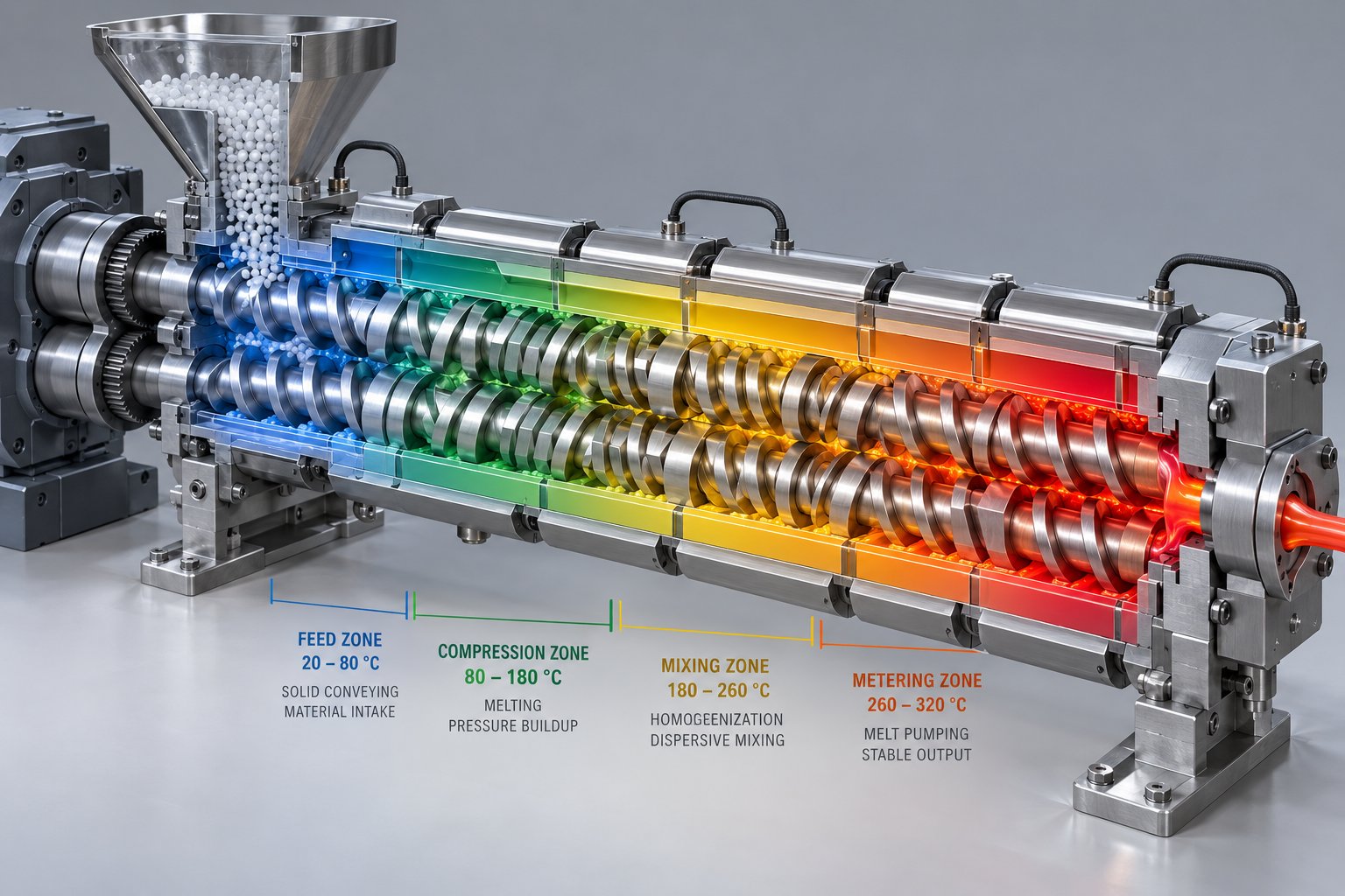
Your five-check diagnostic pointed toward a thermal problem in the barrel. But which zone? A barrel temperature profile is not a single setting — it's a carefully orchestrated gradient where each zone performs a distinct function in transforming PVC dry blend into a fully fused, homogeneous melt. Adjusting the wrong zone doesn't just fail to fix the defect; it can introduce an entirely new one. Understanding PVC extrusion barrel temperature settings by zone transforms reactive guessing into precise, targeted correction.
A typical rigid PVC extrusion barrel — whether running on a conical twin screw or a parallel twin screw — divides into several thermal zones: the feed zone, one or more compression/transition zones, the metering zone, the adapter, and the die. Each zone interacts with screw geometry, material rheology, and residence time in ways that directly determine product quality.
Feed Zone and Compression Zone Temperature Diagnostics
The feed zone is where PVC dry blend or pellets first enter the barrel. Its job is straightforward: accept material consistently and begin gentle heating without premature fusion. Think of it as the on-ramp to a highway — it needs to keep traffic flowing smoothly, not cause a pileup at the entrance.
When the PVC extruder feed zone temperature is too high, the compound begins fusing prematurely against the barrel wall. This creates a partially gelled layer that restricts fresh material from entering — a condition called bridging. You'll notice output drops, screw speed stays constant, and motor amps may decrease because less material is being conveyed. Surging — a rhythmic pulsation in output and melt pressure — is another telltale sign. The extrudate wall thickness fluctuates in a repeating cycle as the feed alternates between starved and flooded conditions.
When the feed zone runs too cold, the opposite problem emerges. Material enters the compression zone insufficiently preheated, requiring more energy from shear and downstream heating to achieve fusion. The result is inconsistent feeding, erratic melt pressure, and potentially under-fused output with visible defects.
For rigid PVC extrusion, feed zone temperatures generally sit at the lower end of the barrel profile — often in the range of 150-165°C (300-330°F), though exact values depend on the specific formulation and machine design. The key principle is that the feed zone should be warm enough to soften and compact the PVC particles without initiating significant gelation.
The compression zone is where the real transformation begins. Here, increasing screw compression works in concert with rising temperature to drive PVC particle fusion — the breakdown of primary particle boundaries and the beginning of molecular interdiffusion. Temperature in this zone typically climbs 10-20°C above the feed zone, creating the thermal energy gradient that, combined with mechanical shear, initiates gelation.
Under-temperature in the compression zone is one of the most common sources of surface defects in PVC extrusion. When particles don't receive enough thermal energy to break down their grain structure, they pass through as partially fused or unfused inclusions. These appear as fish eyes — small, hard, translucent or opaque spots embedded in the extrudate — or as a generally rough, matte surface texture that no amount of die polishing will correct. If you're seeing these symptoms, the compression zone temperature profile is one of the first places to investigate.
Over-temperature in this zone carries a different and equally serious risk. PVC's thermal degradation begins when processing temperatures push past the compound's stabilizer protection capacity. The visual evidence progresses from subtle yellowing to brown discoloration, then to black specks from localized burning. In severe cases, the unmistakable sharp odor of HCl gas confirms active decomposition. PVC is inherently sensitive to heat, and the compression zone — where shear-generated heat adds to conductive heat from the barrel — is particularly vulnerable to thermal overshoot.
Metering Zone, Adapter, and Die Temperature Adjustments
The metering zone sits at the end of the screw's working length, and its primary job is delivering a homogeneous, consistently pressurized melt to the die. Temperature here directly influences melt viscosity, which in turn controls pressure stability and output uniformity. If metering zone temperature is too low, the melt remains excessively viscous, driving up back-pressure and motor load while producing a melt that resists uniform flow distribution in the die. Too high, and you risk over-processing — reducing melt viscosity beyond optimal levels, potentially degrading the PVC, and losing the melt strength needed for dimensional stability.
A useful diagnostic clue: if your melt pressure reading at the adapter fluctuates rhythmically despite steady screw speed and consistent feed, the metering zone temperature may need fine-tuning. Stable metering zone conditions produce stable pressure. Instability here often points to a mismatch between metering zone temperature and the melt viscosity needed for smooth die flow.
The adapter — the short section connecting the barrel exit to the die — serves as a critical thermal bridge. It's easy to overlook, but adapter temperature plays an outsized role in maintaining the melt quality that the barrel worked so hard to achieve. Set it too low, and the melt cools and stiffens, creating pressure spikes and potential flow imbalance at the die entry. Set it too high, and extended residence time at elevated temperature promotes degradation — especially in dead spots where melt flow is sluggish.
Die temperature is where barrel processing meets final product quality. It directly controls surface finish, flow balance across the die cross-section, and dimensional accuracy of the finished profile or pipe. Low die temperatures produce higher melt viscosity at the die land, resulting in rough surfaces, potential melt fracture (sharkskin texture), and increased die pressure. High die temperatures can cause die drool — material oozing or stringing at the die lips — along with dimensional instability as the over-softened extrudate struggles to hold its shape in the calibration stage.
How to set barrel temperatures for rigid PVC extrusion depends on the specific compound and product geometry, but the zone-by-zone diagnostic matrix below captures the general patterns that experienced operators rely on:
| Zone | Common Symptom If Too Low | Common Symptom If Too High | First Corrective Step |
|---|---|---|---|
| Feed Zone | Inconsistent feeding, surging, erratic output | Bridging, reduced output, premature fusion | Adjust in 5°C increments; verify feed throat cooling |
| Compression Zone | Fish eyes, rough surfaces, unfused particles | Yellowing, black specks, HCl odor | Cross-check screw speed; inspect thermocouple accuracy |
| Metering Zone | High melt viscosity, pressure instability, elevated motor amps | Over-fusion, reduced melt strength, degradation risk | Verify melt pressure trend; adjust in small increments |
| Adapter | Pressure spikes, flow imbalance at die entry | Thermal degradation in dead spots, discoloration | Match adapter temp to metering zone; check for material hang-up |
| Die | Rough surface, melt fracture, high die pressure | Die drool, dimensional instability, soft extrudate | Adjust die lips or land length; balance with external lubricant level |
This matrix is your quick-reference diagnostic tool. When a defect appears and your initial five-check sequence points toward thermal causes, match the symptom pattern to the zone and apply the corresponding first corrective step before exploring deeper root causes.
Melt Temperature Measurement Best Practices
Here's a detail that catches many operators off guard: the PVC melt temperature vs barrel set point difference can be surprisingly large. Your barrel zone controller displays the temperature of the barrel wall — the set point and the thermocouple reading embedded in the barrel steel. But the actual melt temperature inside the channel, the temperature that truly determines fusion quality and degradation risk, is often 10-20°C different from the barrel reading.
Why the gap? Two factors dominate. First, shear-generated heat from screw rotation adds thermal energy directly to the melt that barrel thermocouples cannot fully detect. At higher screw speeds, this shear contribution increases substantially, pushing actual melt temperature above barrel set points — sometimes significantly. Second, PVC's relatively poor thermal conductivity means the melt core temperature can lag behind the barrel wall temperature, especially in larger-diameter extruders or at higher throughputs.
Melt temperature at the adapter — measured by an immersion thermocouple that penetrates into the melt stream — provides the most accurate single-point reading of what the PVC compound is actually experiencing. This is the number that matters most for diagnosing fusion and degradation issues. If your extruder doesn't have an immersion melt thermocouple, consider it a high-priority addition.
Handheld pyrometer readings at the die face are useful for quick checks, but they measure surface temperature of the extrudate, which cools rapidly upon exposure to air. Pyrometer readings typically run 10-30°C below actual melt temperature at the die exit, depending on line speed and ambient conditions. Treat them as directional indicators, not absolute values.
The practical takeaway: when your diagnostic process points to a thermal root cause, always reference actual melt temperature data rather than barrel set points alone. A barrel zone reading exactly on target means little if the melt thermocouple shows the PVC is 15°C hotter or cooler than intended. That hidden gap between set point and reality is where many persistent temperature-related defects quietly originate — and it's also where the boundary between proper fusion and thermal degradation gets crossed without anyone noticing the barrel controllers.
Temperature precision, however, only tells you whether the compound reached the right thermal window. It doesn't tell you whether the PVC actually fused correctly once it got there. Fusion — or more precisely, gelation — is a process with its own diagnostic science, and a compound can hit the perfect melt temperature yet still produce under-fused or over-fused output depending on shear history, formulation, and residence time.
PVC Fusion and Gelation Defect Diagnosis
Polyethylene melts. Polypropylene melts. PVC does something far more complicated — and that difference is exactly why a barrel temperature reading alone can never tell you whether your product will pass mechanical testing. PVC undergoes a multi-stage fusion process called gelation, where the original powder particles must be physically broken apart and their molecular chains interdiffused to build a strong, continuous polymer network. Get the gelation level wrong in either direction and you'll produce extrudates that look acceptable on the surface but fail catastrophically in service.
This distinction matters enormously for PVC extrusion troubleshooting because gelation-related defects don't always announce themselves with obvious visual symptoms. A pipe might emerge from the die looking perfectly smooth, yet shatter on impact during quality testing because its fusion level never reached the threshold for adequate toughness. Understanding how to diagnose and correct gelation problems — not just temperature problems — separates effective process engineers from operators who are perpetually chasing symptoms.
Understanding PVC Gelation and Why It Matters
Imagine a jar of popcorn kernels. Suspension PVC resin arrives as particles roughly 100-200 microns in diameter, each with a distinctive porous, grain-like morphology. Beneath the outer skin of each particle sit much smaller structures — primary particles approximately one micron in size — held together by weak physical bonds. During extrusion, heat and mechanical shear must accomplish a very specific sequence of transformations to turn those loose grains into a functional engineering material.
The gelation process unfolds in four overlapping stages:
- Particle compaction. The loose PVC powder is compressed and densified by the screw's conveying action. Air is expelled and particles begin contacting each other under pressure.
- Primary particle breakdown. As temperature and shear increase, the outer grain boundaries fracture and the internal primary particles are released. This is where the original "popcorn" structure disintegrates.
- Molecular interdiffusion. Freed PVC chains from adjacent primary particles begin migrating across the old particle boundaries, entangling with chains from neighboring particles. This entanglement is the mechanism that actually builds mechanical strength.
- Network formation. Sufficient interdiffusion creates a continuous, entangled polymer network throughout the melt. The original particle boundaries effectively disappear, replaced by a homogeneous structure with strong inter-particle bonding.
Here's the critical insight: PVC's engineering properties come directly from fusion, not simply from reaching a target temperature. A compound can hit 190°C and still be under-fused if shear history was insufficient to break down primary particles and drive chain entanglement. Conversely, excessive processing can push gelation beyond the optimal window, destroying the residual crystalline structure that contributes to impact resistance.
Under-fusion produces extrudates with poor impact strength, visible fish eyes — those small hard spots where intact primary particles survived the extrusion process — rough internal surfaces, and a tendency toward delamination under mechanical stress or pressure testing. The PVC under-fusion fish eyes cause and fix equation almost always traces back to insufficient particle breakdown, whether from low temperatures, inadequate shear, excessive external lubricant, or some combination of all three.
Over-fusion creates its own set of problems, and they're often counterintuitive. You might expect that more fusion always means better properties, but PVC over-fusion impact strength reduction is a well-documented phenomenon. When gelation pushes past roughly 80-90% of the theoretical maximum, the residual crystalline domains that act as energy-absorbing reinforcement points within the polymer matrix are destroyed. The result is a fully homogeneous but overly processed melt that actually loses toughness. Over-fusion also wastes energy, increases thermal degradation risk, and raises the probability of discoloration from extended heat exposure.
Diagnosing Under-Fusion vs Over-Fusion on the Production Line
So how do you determine whether your extrudate's gelation level is actually in the right range? Several practical diagnostic methods are available, ranging from simple shop-floor techniques to laboratory-level analysis.
Visual inspection provides the quickest initial read. For rigid PVC pipe and profile, surface gloss is a rough proxy for gelation — under-fused material tends to exhibit a matte, dull finish because incompletely fused particle remnants scatter light. Well-fused PVC shows a smooth, glossy surface. In clear or translucent PVC formulations, transparency itself becomes a diagnostic tool: under-fused material appears hazy because residual particle boundaries act as optical scattering centers, while properly fused material is clear.
Acetone immersion testing is the most widely used shop-floor method for how to test PVC fusion degree acetone immersion. Cut a small sample from the extrudate, immerse it in acetone for a controlled time period (typically 10-30 minutes, depending on the protocol), then examine the result. Under-fused PVC absorbs acetone rapidly and swells, whitens, or disintegrates because the solvent penetrates along unfused particle boundaries. Well-fused material resists acetone penetration and retains its shape and color. The degree of swelling or disintegration correlates directly with the fusion level — heavily swollen or crumbled samples indicate seriously deficient gelation.
Differential Scanning Calorimetry (DSC) provides the most precise laboratory-level confirmation. DSC measures the thermal history of the processed PVC by detecting endothermic peaks related to crystalline melting. As technical analysis confirms, typical rigid PVC crystallinity values fall in the 4-10% range, and DSC can estimate the processing temperature the material actually experienced. This helps engineers verify whether the compound reached the intended thermal window and achieved the target fusion level. While DSC requires lab equipment and trained interpretation, it's invaluable for resolving disputes between formulation-related and process-related fusion problems.
The following table provides a side-by-side comparison to help you distinguish under-fusion from over-fusion on the production line:
| Property | Under-Fusion Indicator | Over-Fusion Indicator |
|---|---|---|
| Surface appearance | Matte, dull, granular texture | Very high gloss, potentially with slight yellowing |
| Fish eyes | Present — hard, translucent or opaque spots | Absent |
| Impact strength | Low — brittle failure in drop or Charpy tests | Reduced — ductile-to-brittle transition from over-processing |
| Acetone immersion | Rapid swelling, whitening, or disintegration | Minimal absorption; sample remains intact |
| Internal pipe surface | Rough, pitted, or layered texture | Smooth but may show discoloration |
| Transparency (clear PVC) | Hazy, milky appearance | Clear but potentially yellow-tinted |
| Weld line strength | Weak — fails easily under pressure | Adequate to good |
| Thermal stability margin | Adequate — stabilizer not yet consumed | Reduced — stabilizer partially consumed by excessive heat history |
Corrective Actions for Fusion Problems
When PVC gelation level troubleshooting extrusion points to a fusion problem, the temptation is to immediately raise barrel temperatures. Sometimes that's the right move — but not always. In fact, increasing temperature alone carries real risk because it adds thermal energy without necessarily improving the mechanical breakdown of primary particles, and it accelerates stabilizer consumption. A more effective approach follows a structured adjustment hierarchy that addresses the most likely root causes in order of impact and safety.
First, check the formulation. Acrylic processing aids are specifically designed to accelerate PVC fusion by improving shear transfer between particles and promoting molecular entanglement. If processing aid levels are too low — or if a formulation change reduced them — fusion will suffer regardless of barrel settings. Similarly, lubricant balance plays a decisive role. Excessive external lubricant (like paraffin wax) creates a slippery boundary layer between PVC particles and the barrel wall, reducing the shear energy transmitted to the compound and delaying fusion. Too much internal lubricant can also interfere with the development of a robust entangled network. If a defect appeared after a formulation change, the compound is the prime suspect.
Second, review the barrel temperature profile. If the formulation hasn't changed, examine the compression and metering zone temperatures relative to your proven baseline. Increasing compression zone temperature by 3-5°C increments can improve fusion — but always verify the response through actual melt temperature readings, not just the barrel set point. Remember the gap discussed in the previous section: barrel wall readings may not reflect what the melt is truly experiencing.
Third, evaluate screw speed. This is the corrective action many operators overlook. Increasing screw speed raises shear energy input, which directly promotes primary particle breakdown and chain interdiffusion — the physical mechanisms that drive gelation. A modest increase in screw RPM can improve fusion more effectively and safely than a large temperature increase because shear energy is distributed throughout the melt rather than conducted from the barrel wall inward. The trade-off is increased output rate, which must be balanced against downstream capacity.
Fourth, consider back-pressure adjustments. Increasing back-pressure through screen pack changes, die restriction, or adjustable throttle valves extends residence time and increases shear in the metering zone. This gives the PVC compound additional processing time and energy to achieve complete fusion. Use this lever judiciously — excessive back-pressure raises melt temperature and risks degradation, particularly in formulations with marginal stabilizer levels.
The most effective fusion correction often combines modest shear increases with targeted temperature adjustments, rather than relying on temperature alone. Shear breaks particles apart; temperature helps the freed chains move and entangle.
Every fusion correction you make should be validated. Run an acetone immersion test on a sample taken after the process stabilizes. Compare impact test results if your quality protocol requires them. Document the new settings as part of your updated process baseline. And if the fusion problem persists despite optimized barrel temperatures and screw speed, the investigation needs to expand — because defects that resist parameter optimization often have their true origins in the compound itself, in ways that look identical to machine-driven problems but require entirely different solutions.
Surface Defect Differential Diagnosis for PVC Extrusion
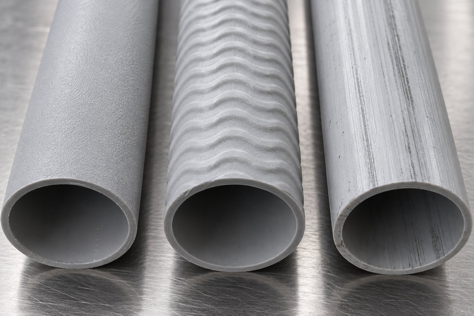
A rough surface is a rough surface, right? Not even close. One of the most persistent traps in PVC extrusion troubleshooting is treating surface defects as interchangeable symptoms with a single fix. In reality, two extrudates can look remarkably similar coming off the die — both rough, both subpar — yet originate from entirely different mechanisms that demand opposite corrective actions. Raise die temperature to fix one, and you'll make the other worse. That's why differential diagnosis — the practice of distinguishing between look-alike defects based on their specific characteristics — is arguably the most valuable skill a PVC operator can develop.
The same logic applies to bubbles, voids, and discoloration. Each symptom has multiple possible root causes, and the fix for moisture-driven bubbles is useless against degradation-driven gas voids. The sections below break down the most common PVC surface defects into their distinct subtypes, giving you the diagnostic markers to identify each one correctly before committing to a corrective action.
Surface Roughness From Three Different Root Causes
Surface roughness is the single most frequently reported PVC extrusion surface defect — and the most frequently misdiagnosed. Three distinct mechanisms produce rough surfaces, each with its own visual signature, timing pattern, and correction path. Learning to tell them apart saves hours of wasted adjustments.
1. Surface roughness from incomplete PVC fusion. This is the roughness that confuses operators the most because it doesn't respond to die-side fixes. The texture is matte and granular, almost like fine sandpaper. You can polish the die land to a mirror finish, and the roughness returns immediately because the defect originates upstream in the barrel. Incompletely fused PVC particles — remnants of the original grain structure that survived the gelation process — reach the die as a heterogeneous melt with embedded hard spots. These partially fused inclusions disrupt the smooth flow of material through the die land, producing a uniformly rough surface from the moment the line starts. The roughness is consistent and does not worsen progressively over time. The fix lies in improving fusion: adjusting compression zone temperatures, increasing screw speed for more shear energy, or reviewing processing aid and lubricant levels in the formulation.
2. Surface roughness from melt fracture. This one looks distinctly different if you know what to look for. Instead of a uniform granular texture, you'll see a repeating pattern — sharkskin ridges, a wavy stick-slip texture, or regular transverse lines across the extrudate surface. This is the classic PVC melt fracture sharkskin fix scenario. The root cause is excessive shear stress at the die land: the melt velocity at the die wall alternates between sticking and slipping, creating the characteristic patterned distortion. Unlike fusion-related roughness, melt fracture responds directly to die-side interventions — reducing output rate to lower shear velocity, increasing die temperature to reduce melt viscosity at the land, widening the die gap, or increasing external lubricant levels to reduce wall friction. If you increase barrel temperature to fix this defect without addressing die conditions, you risk degradation without resolving the shear stress problem.
3. Surface roughness from die buildup (plate-out). Here's the telltale timing clue: this roughness gets progressively worse. The line starts clean and the initial product looks fine. Over minutes or hours, streaks, lines, or drag marks begin appearing on the extrudate surface, gradually worsening in severity. The cause is lubricant, stabilizer, or additive migration that accumulates as a deposit on the die land surfaces. This buildup — called plate-out — creates physical obstructions that score or drag across the extrudate as it exits. PVC die plate-out buildup prevention starts with formulation review: excessive external lubricant, incompatible stabilizer systems, or high filler loading all promote plate-out. The immediate fix is die cleaning, but if the problem recurs within the same production run, the formulation balance needs adjustment.
The table below puts all three side by side so you can quickly match what you're seeing on the line to the correct root cause:
| Defect Type | Visual Appearance | Touch Texture | Timing Pattern | Primary Root Cause | First Fix |
|---|---|---|---|---|---|
| Incomplete fusion roughness | Uniform matte, granular surface | Fine sandpaper feel | Present from startup; consistent over time | Insufficient gelation in barrel | Increase compression zone temperature or screw speed; review processing aid level |
| Melt fracture (sharkskin) | Repeating ridges, wavy stick-slip pattern | Regular ridged texture | Present at startup; worsens with increased output rate | Excessive shear stress at die land | Reduce output rate, increase die temperature, or increase external lubricant |
| Die buildup (plate-out) | Progressive streaks, lines, or drag marks | Intermittent raised lines or grooves | Develops gradually; worsens over time during the run | Lubricant/stabilizer migration and accumulation on die surfaces | Clean die; review external lubricant level and stabilizer compatibility |
Notice how the timing pattern alone narrows the diagnosis considerably. A roughness present from the first meter of extrudate points to fusion or melt fracture. A roughness that develops gradually over the production run points to plate-out. This single observation — "was it there from the start?" — is your most efficient first diagnostic question for any PVC extrusion surface roughness problem.
Distinguishing Bubbles, Voids, and Porosity in PVC Extrudates
Bubbles in PVC extrudate trigger an immediate alarm on any production line. But the word "bubble" covers at least three distinct phenomena — and the corrective actions for each are completely different. Treating a degradation void like a moisture bubble, or a calibration defect like a material problem, wastes time and often makes the situation worse.
Moisture-related bubbles originate from water vapor trapped in hygroscopic additives within the PVC compound. PVC resin itself has low moisture absorption, but common formulation ingredients — calcium carbonate fillers, acrylic impact modifiers, and especially wood flour in WPC compounds — readily absorb ambient humidity. During extrusion, this trapped moisture vaporizes under barrel heat and pressure. When the melt exits the die and pressure drops, the steam expands into visible bubbles. These bubbles are typically small, numerous, and distributed relatively uniformly throughout the extrudate cross-section. They tend to appear more frequently in humid conditions or after raw materials have been stored improperly.
The fix for moisture-driven bubbles targets the water source directly. Pre-drying hygroscopic additives before blending, maintaining sealed storage for finished dry blends, and using barrel venting to allow moisture vapor to escape before the melt reaches the die are all effective countermeasures. A simple diagnostic test confirms moisture as the culprit: take a small sample of the dry blend, heat it in an oven at 105°C for two hours, and compare the extrusion result. If bubbles disappear or significantly diminish, moisture was the root cause.
Degradation-related gas voids look different and behave differently. When PVC overheats past its thermal stability limit, the polymer chain begins releasing hydrogen chloride (HCl) gas. These voids tend to be larger and more irregular than moisture bubbles, sometimes appearing as elongated cavities aligned with the flow direction. They're often accompanied by discoloration — yellowing or browning near the void — and in severe cases, a sharp acidic odor is detectable at the die exit. Unlike moisture bubbles, degradation voids worsen as the line runs because the thermal damage is cumulative: stabilizer depletion accelerates once it begins.
Corrective action here is fundamentally different from the moisture protocol. Barrel temperatures need immediate review — particularly compression and metering zones where shear heat combines with conductive heat. Stabilizer levels in the formulation require verification. And critically, any dead spots in the barrel, adapter, or die where material can stagnate and overheat must be identified and eliminated.
Vacuum calibration-related porosity is the third category, and it's the one most often confused with material-driven bubbles. This porosity typically appears near the outer wall of pipe or the surface of profiles — the regions most directly affected by the vacuum calibration process. When vacuum is excessive, it can pull dissolved gases or micro-voids toward the outer surface. When vacuum is insufficient or uneven, the extrudate doesn't seat fully against the calibration sleeve, leaving surface porosity or rough patches. The distinguishing feature is location: calibration-related porosity concentrates near the outer surface rather than distributing uniformly through the wall thickness.
Diagnosing which type of bubble or void you're dealing with comes down to three questions: Where in the cross-section are they located? Did they appear suddenly or develop gradually? And are they accompanied by discoloration or odor? Your answers point directly to the mechanism — and the fix.
Discoloration Patterns and What They Reveal
Color changes in PVC extrudates are more than cosmetic failures — they're diagnostic signals that reveal what's happening inside the barrel, adapter, and die. Three distinct discoloration patterns show up regularly, and each tells a different story about the process condition.
Yellowing from thermal degradation is the most common and most concerning. It indicates that the PVC compound has exceeded its thermal stability window, either from excessive barrel temperatures, too much shear heating, or depleted stabilizer. Yellowing typically appears uniformly across the extrudate cross-section and intensifies progressively during the run as the stabilizer system is consumed. Early-stage yellowing may be subtle — detectable only when comparing the extrudate against a color standard or a sample from the beginning of the run. Advanced yellowing is obvious and signals that the compound's heat stabilizer reserve is critically low. The fix starts with reducing thermal input: lower barrel zone temperatures, reduce screw speed to decrease shear heating, and verify that stabilizer levels in the formulation are adequate.
Brown or black specks point to a completely different mechanism — localized material degradation from dead spots or hang-up areas. These are points in the barrel, adapter, breaker plate, or die where PVC melt sits stagnant for extended periods, eventually charring into dark, carbonized particles that periodically break free and contaminate the melt stream. As industry observations confirm, wear or corrosion on mold surfaces can cause stripes and surface defects that reduce overall product quality. Black specks in PVC extrusion causes almost always trace back to equipment geometry — rough internal surfaces, sharp corners in flow channels, improperly seated screen packs, or worn die components that create stagnation zones. The corrective action is mechanical: disassemble and thoroughly clean the affected components, polish flow surfaces, redesign flow channels to eliminate dead spots, and review purging procedures between production runs.
Color inconsistency or streaking — where the extrudate shows uneven coloration in patches, streaks, or swirls — points to poor dispersion of pigments or additives in the compound. This is fundamentally a mixing problem, not a degradation problem. The colorant or additive particles haven't been uniformly distributed throughout the PVC matrix. Root causes include insufficient mixing time during compound preparation, incompatible carrier resins for color concentrates, degraded mixing elements in the extruder screw, or simply running at too low a screw speed to achieve adequate dispersive mixing. The fix focuses on mixing intensity — upstream in compound preparation or within the extruder through screw speed adjustment or mixing element evaluation.
Each discoloration type demands a distinct diagnostic path. Yellowing says "too much heat or too little stabilizer." Black specks say "clean and inspect your hardware." Color streaking says "improve your mixing." Treating one as the other wastes time and materials while the real problem persists — a pattern that extends beyond surface defects into the compound formulation itself, where the true origin of many persistent PVC processing failures quietly resides.
Formulation Root Causes Behind PVC Extrusion Defects
Every section so far has touched on the same quiet truth: some defects simply refuse to respond to machine adjustments. You optimize barrel temperatures zone by zone. You fine-tune screw speed. You clean and polish the die. And the problem persists. When that happens, the root cause almost certainly lives inside the compound itself — not the equipment processing it.
PVC compounds are not single-ingredient materials. A typical rigid PVC formulation includes the base resin, heat stabilizer, internal and external lubricants, processing aids, impact modifiers, fillers like calcium carbonate, and pigments. Each ingredient influences how the compound behaves under heat and shear, and an imbalance in any one of them can produce extrusion defects that perfectly mimic machine-caused problems. This is the critical gap that most PVC formulation defects extrusion troubleshooting resources fail to address — the compound is treated as a fixed input, when in reality it's one of the most variable and impactful elements on the line.
The diagnostic principle here is straightforward: if a defect appeared after a formulation change — new resin lot, different stabilizer batch, adjusted lubricant levels, or a new filler supplier — the formulation is the prime suspect regardless of what the machine settings show. And even without a deliberate change, ingredient degradation during storage, moisture absorption, or lot-to-lot variability can shift compound behavior enough to push a previously stable process into defect territory.
Stabilizer Depletion Symptoms and Corrective Formulation Adjustments
Heat stabilizers are the bodyguards of the PVC molecule. They neutralize the hydrogen chloride that PVC releases under thermal stress, preventing the autocatalytic degradation cascade that rapidly destroys the polymer. When that protection fails — whether from insufficient dosing, degraded stabilizer chemistry, or excessive thermal demand — the symptoms follow a predictable and progressively worsening pattern.
The earliest sign of PVC heat stabilizer depletion during extrusion is a subtle yellowing of the extrudate. At first, it's barely noticeable — you might only catch it by comparing the current product against a retained color standard from the beginning of the run. As stabilizer reserves decline further, the yellowing deepens to amber, then brown. Localized degradation produces black specks — tiny carbonized particles where the PVC chain has fully decomposed. In severe cases, you'll detect the sharp, acrid odor of HCl gas at the die exit, a signal that degradation has overwhelmed the stabilizer system entirely.
Here's the critical diagnostic distinction: how do you tell stabilizer depletion apart from simple thermal overprocessing? Both produce yellowing and discoloration. Both can generate black specks. The difference lies in the progression pattern. Stabilizer depletion worsens progressively over time even when barrel temperatures remain perfectly stable. The compound gradually exhausts its protective capacity, so the first meter of extrudate looks fine, the hundredth meter shows faint yellowing, and the thousandth meter is noticeably discolored. Thermal overprocessing, by contrast, produces immediate and consistent discoloration that correlates directly with temperature readings — raise the temperature, the yellowing appears; lower it, the yellowing recedes.
If the timing pattern points to stabilizer issues, several corrective paths are available. First, verify stabilizer dosing accuracy. Weighing errors during compound preparation — even small ones — can leave the formulation under-protected. Second, check stabilizer shelf life. Tin-based stabilizer systems, Ca-Zn packages, and lead-free alternatives all have finite storage lives, and some components — particularly organic co-stabilizers like beta-diketones and phosphites — can lose effectiveness if stored in humid or high-temperature conditions. Ca-Zn stabilizers, for instance, typically require co-stabilizers to provide adequate long-term thermal protection, and if those co-stabilizers degrade during storage, the primary stabilizer system appears to fail even at correct dosage levels.
Third, consider whether the process itself is consuming stabilizer faster than intended. Excessive shear from aggressive screw speeds, prolonged residence time from low throughput, or dead spots where material stagnates and overheats can all deplete stabilizer reserves faster than the formulation was designed to handle. In these cases, the fix may involve both formulation adjustment — increasing stabilizer loading or adding more robust co-stabilizers — and process optimization to reduce unnecessary thermal and shear stress on the compound.
Lubricant Imbalance and Its Effects on Processing
If stabilizers protect PVC from chemical degradation, lubricants protect it from mechanical and thermal abuse during processing. And just like stabilizers, lubricant balance is a precision exercise. PVC compounds rely on two functionally distinct types of lubrication working in concert: internal lubricants that reduce friction between PVC molecular chains within the melt, and external lubricants that reduce adhesion between the melt and the hot metal surfaces of the screw, barrel, and die.
A rigid PVC pipe compound, for example, typically carries roughly 1 to 3 phr of total lubricant — a small fraction by weight, yet one that disproportionately controls processability. Calcium stearate serves as the primary internal lubricant and co-stabilizer, paraffin wax provides external lubrication and metal release, and oxidized PE wax delivers additional die release at very low dosages. Shift any component of this balance, and the processing response changes dramatically.
PVC lubricant imbalance internal vs external symptoms show up as distinct, identifiable processing problems. Here's what each imbalance looks like on the production floor:
- Too little internal lubricant: Melt viscosity rises, motor amperage or torque increases noticeably at the same screw speed, and melt pressure climbs. The compound resists flow, generating excess shear heat that can push temperatures past the degradation threshold. Operators often misdiagnose this as a temperature problem and lower barrel settings, which further increases viscosity and worsens the cycle.
- Too much internal lubricant: Fusion is delayed because the lubricant reduces the inter-particle friction that drives gelation. The extrudate may appear under-fused — matte surface, poor impact strength, possible fish eyes — even at normal barrel temperature settings. This is one of the most commonly overlooked causes of fusion deficiency.
- Too little external lubricant: The melt sticks to metal surfaces, particularly the die land. Die pressure rises, surface roughness develops as a stick-slip pattern (melt fracture), and in severe cases the extrudate drags and tears at the die exit. The compound essentially tries to bond to the steel instead of sliding past it.
- Too much external lubricant: Plate-out develops on the die, screw, and calibration surfaces as excess lubricant migrates out of the melt and deposits on metal. Fusion quality suffers because the external lubricant layer between PVC particles and the barrel wall reduces the shear energy transferred to the compound. Surface haze, poor printability, and weld-line weakness in profiles are additional indicators.
The challenge is that these symptoms overlap with machine-caused problems. High motor amps could mean a cold barrel or a lubricant-starved compound. Melt fracture could mean a die temperature issue or an external lubricant deficiency. The diagnostic key is context: did the symptom appear after a material batch change? Has the same machine run this product successfully before at identical settings? If the machine history checks out but the material lot is different, the lubricant balance deserves scrutiny.
One particularly tricky interaction involves the Ca-Zn stabilizer systems that have replaced lead-based stabilizers across much of the industry. Lead stabilizers inherently provided some lubrication, whereas Ca-Zn systems generally require more external lubricant to compensate for the loss of that built-in lubricity. Processors who switched stabilizer systems without rebalancing the lubricant package often experience persistent processing difficulties that no machine adjustment can resolve.
Filler Loading, Impact Modifier, and Processing Aid Interactions
Beyond stabilizers and lubricants, three other formulation variables quietly shape extrusion behavior in ways that can produce confounding defects: calcium carbonate filler loading, impact modifier levels, and acrylic processing aid content.
Calcium carbonate filler is the most widely used filler in rigid PVC, added to reduce cost and improve stiffness. But high CaCO3 loading introduces two specific problems for PVC extrusion. First, calcium carbonate is hygroscopic — it absorbs ambient moisture that vaporizes during processing and creates bubbles in the extrudate. The finer the particle size and the higher the loading, the greater the moisture risk. Using stearic acid-coated CaCO3 grades helps by reducing the filler's surface energy and moisture absorption, but it also changes the lubricant balance since the coating itself acts as a mild lubricant. Second, high filler loading increases melt viscosity significantly, raising motor load and shear heat generation. Fillers can also adsorb stabilizer molecules on their surface, effectively reducing the active stabilizer available to protect the PVC matrix. A new filler lot with higher surface area than the previous supply can cause calcium carbonate filler PVC extrusion problems that mimic stabilizer depletion — progressive yellowing and reduced thermal stability — despite no change in stabilizer dosage.
Impact modifiers — typically acrylic (MBS) or chlorinated polyethylene (CPE) types — alter the melt's rheological behavior and fusion characteristics. Higher impact modifier content generally increases melt viscosity and can delay fusion onset, requiring adjustments to barrel temperature or screw speed to maintain the same gelation level. Impact modifiers are also frequently hygroscopic, compounding the moisture-related bubble risks from fillers. When both filler loading and impact modifier content are high, the combined moisture burden can overwhelm barrel venting capacity, producing persistent bubble defects that no amount of temperature adjustment can eliminate — only pre-drying of the raw materials resolves it.
Acrylic processing aids occupy the opposite end of the fusion spectrum. These additives promote PVC fusion by increasing melt elasticity and shear transfer efficiency between particles, effectively accelerating the gelation process. They counteract the fusion-delaying effects of external lubricants — an interaction documented extensively in PVC processing literature. When processing aid levels drop — whether from a formulation change, a raw material substitution, or simple dosing error — fusion quality declines even though all machine parameters remain constant. The compound takes longer to gel, output may appear under-fused, and surface quality deteriorates. Operators instinctively respond by raising barrel temperatures, which partially compensates but increases degradation risk and stabilizer consumption unnecessarily.
The troubleshooting logic for formulation-related defects follows one overarching principle: trace the timeline. When did the defect first appear? Did anything change in the raw materials — new lots, new suppliers, different storage conditions? Did the formulation itself change, even slightly? If the defect correlates with a material change, address the material first. Running a retained sample of the previous compound batch through the same machine at the same settings provides the definitive test: if the old material runs clean and the new material produces the defect, the root cause is unambiguously formulation-driven.
This formulation-versus-machine diagnostic approach is essential — but there's one machine variable that behaves almost like a formulation issue in how fundamentally it shapes PVC processing outcomes. Screw design and screw condition directly determine how much shear energy reaches the compound, how uniformly the melt is processed, and whether the barrel can even achieve proper fusion at any temperature setting. When a screw no longer matches the process requirements, the symptoms look eerily similar to formulation problems, creating one of the most difficult differential diagnoses in PVC extrusion.
How Screw Design Impacts PVC Processing and Defect Generation
A perfectly balanced formulation and a flawless temperature profile still can't produce quality extrudate if the screw geometry doesn't match the process demands. The screw is the engine of fusion — it determines how much shear energy reaches the PVC compound, how uniformly that energy is distributed, and whether the melt exits the barrel in a homogeneous, properly gelled state or as a partially processed mess. Yet when persistent defects resist every temperature and formulation adjustment, screw design and screw condition are often the last variables anyone investigates. That's a costly oversight.
Understanding the relationship between screw geometry and PVC processing behavior transforms your troubleshooting from a surface-level parameter chase into a root cause investigation that reaches the mechanical heart of the extruder.
Compression Ratio, L/D Ratio, and Mixing Section Design for PVC
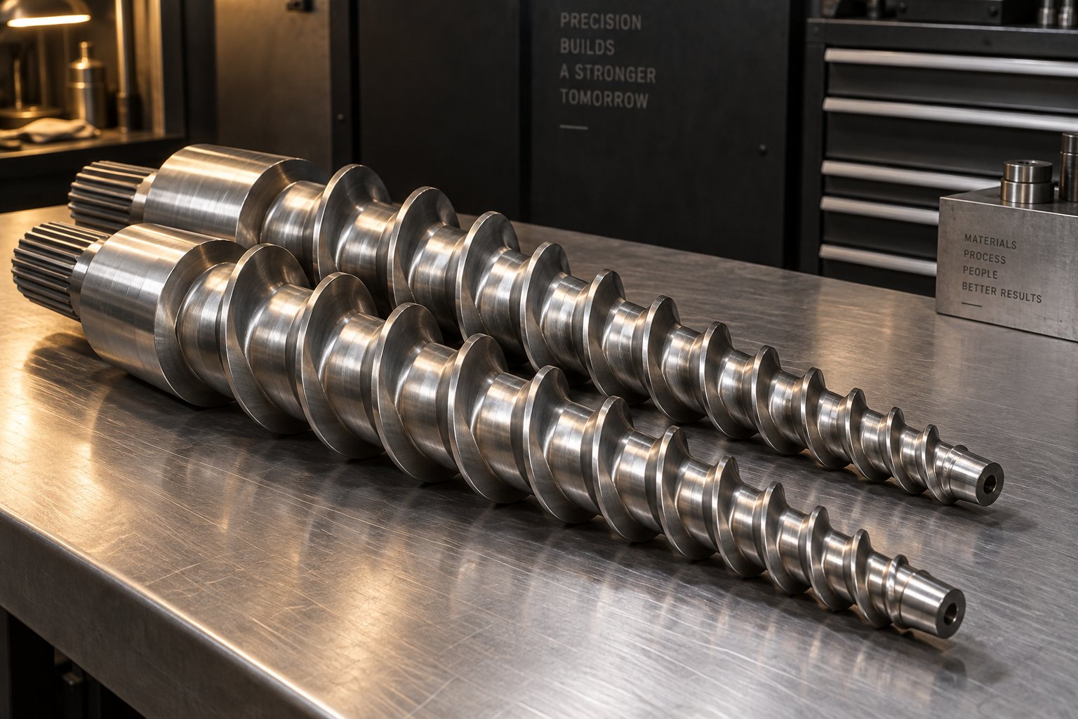
For rigid PVC extrusion — pipe, profile, board, foam board, WPC — the conical twin screw barrel is the dominant plasticizing design, and for good reason. Picture two intermeshing screws whose diameters taper from a large feed end to a smaller discharge end, rotating inside a matching tapered barrel. That geometry delivers a critical advantage for PVC: a large feed zone intake area that accepts bulky dry blend efficiently, tapering progressively to a smaller metering section that builds pressure and compacts the material gently but thoroughly.
Why does this matter for a heat-sensitive polymer like PVC? The conical taper spreads compression gradually along the barrel length rather than concentrating it in a short transition zone. This produces even heat distribution and reduced energy consumption compared to designs that rely on aggressive, localized compression. The counter-rotating action of the twin screws provides positive conveying — material is pushed forward mechanically rather than relying solely on drag flow — which gives conical systems excellent self-feeding capability for rigid PVC dry blends.
The compression ratio effect on PVC fusion quality is direct and significant. Compression ratio describes how much the available channel volume decreases from the feed end to the discharge end. Too aggressive a compression ratio — where channel volume drops sharply — generates excessive shear heat in a short barrel section. For PVC, that localized thermal spike can push the compound past its degradation threshold even when barrel zone temperatures look perfectly safe. The melt thermocouple shows a number; the screw geometry determines whether that number represents uniform processing or a dangerously uneven thermal history.
Insufficient compression creates the opposite failure. Without adequate mechanical work, PVC primary particles don't break down fully. The melt exits the barrel under-fused, producing fish eyes, poor impact strength, and rough surfaces that no amount of temperature increase can fully correct — because the problem isn't thermal energy, it's mechanical energy. The screw simply isn't doing enough physical work on the compound.
Mixing sections or kneading elements along the screw length play a supporting role by redistributing the melt and improving thermal homogeneity. Well-designed mixing elements break up any remaining particle agglomerates and ensure uniform temperature distribution across the melt cross-section — without introducing the intense, localized shear that could degrade PVC. Poorly designed or worn mixing elements, conversely, create dead zones where material stagnates and overheats, contributing to black specks and discoloration.
The table below highlights the key differences between conical and parallel twin screw designs for PVC processing:
| Design Aspect | Conical Twin Screw Barrel | Parallel Twin Screw Barrel |
|---|---|---|
| Geometry | Tapered diameter; axes at an angle | Constant diameter; parallel axes |
| Feed zone capacity | Large intake area; excellent self-feeding for dry blends | Smaller relative feed volume; may need force-feeding |
| Bearing and torque capacity | Larger bearings; higher load and torque resistance | Smaller bearings; lower torque capacity |
| Compression profile | Gradual, geometry-driven compression along full length | Compression depends on screw element configuration |
| Typical PVC applications | Pipe, profile, board, foam board | Profiles, WPC, cable ducts, window frames |
| Space requirement | More compact footprint | Longer machine length for equivalent L/D |
This isn't an academic distinction. When a conical twin screw barrel PVC extrusion system is properly matched to the product and formulation, it delivers the gentle-yet-thorough plasticizing that PVC's thermal sensitivity demands. When the match is wrong — whether from an undersized screw for the throughput requirement, an incorrect compression ratio for the formulation, or simply the wrong barrel type for the application — the resulting defects resist every parameter adjustment you throw at them.
Recognizing Screw Wear as a Defect Source
Even the perfectly matched screw eventually wears. And wear doesn't announce itself with a single dramatic failure — it creeps in gradually, eroding process capability so slowly that operators compensate without realizing they're masking a deteriorating mechanical condition. Recognizing PVC extruder screw wear symptoms and diagnosis patterns early saves significant scrap, downtime, and frustration.
The fundamental mechanism is straightforward. As screw flights wear, the clearance between the flight tip and the barrel wall increases. This widening gap allows more material to leak backward over the flights instead of being conveyed forward, reducing the screw's compression effectiveness and its ability to generate the mechanical shear PVC needs for proper fusion. As extrusion wear research documents, the main signs of wear include a reduction in specific rate — the output per revolution of the screw — and higher discharge temperatures as leakage flow increases and heat transfer efficiency drops.
Imagine running a line that produced excellent pipe six months ago at 35 RPM. You're now running the same product at 42 RPM to maintain output, the melt temperature is running hotter than baseline, and reject rates have crept up despite no formulation or setting changes. That's the classic wear progression in action.
Here are the specific symptoms that point to screw wear as the defect source:
- Declining output at constant screw speed: You need higher RPM to hit the same kg/hr target. This is the earliest and most reliable wear indicator — the specific rate (output divided by screw speed) drops measurably.
- Increasing melt temperature variability: Worn flights allow uneven material flow, creating hot spots and cold spots in the melt. Melt temperature readings at the adapter become less stable, fluctuating where they previously held steady.
- Higher discharge temperatures at the same output: With increased leakage flow and reduced heat transfer efficiency at the barrel wall, the melt absorbs more energy per unit of material processed. Discharge temperatures rise even without changing barrel set points.
- Surging or output pulsation: Worn compression zones lose their ability to maintain consistent forward pressure. The result is periodic output fluctuation — the extrudate diameter or wall thickness cycles rhythmically, and melt pressure readings oscillate.
- Inconsistent fusion quality: Because worn screws deliver less mechanical shear to the compound, fusion levels drop. Fish eyes reappear in products that previously ran clean. Acetone immersion tests show increasing swelling. Impact test results decline.
- Rising reject rates with unchanged settings: This is the cumulative effect of all the above. The process window narrows as wear progresses — the range of settings that produce acceptable product shrinks until eventually no combination of temperatures and speeds yields consistent quality.
One particularly deceptive aspect of screw wear is how operators unconsciously adapt. A few extra RPM here, a slight temperature bump there — each individual adjustment seems minor, but collectively they drift the process far from its original baseline. This is precisely why tracking baseline parameters (covered in the preventive maintenance section) matters so much. Without documented baselines, gradual wear is invisible until the process falls off a cliff.
For reference, new flight clearance on a plasticating extruder is typically the nominal screw diameter divided by 1000 per side. A 90mm conical twin screw, for example, starts with roughly 0.09mm (0.0035 in.) clearance per side. As that clearance doubles and triples, every symptom listed above intensifies. Some applications tolerate more wear than others — non-critical products like drainage pipe may run acceptably at higher clearances, while precision profiles and pressure-rated pipe demand much tighter tolerances.
When to Evaluate Screw Replacement or Upgrade
Knowing when to replace a PVC extruder screw barrel is ultimately an economic and quality decision, but several concrete criteria help frame that judgment objectively rather than waiting for a catastrophic failure.
Measurable flight clearance increase is the most direct indicator. Industry guidelines suggest evaluating replacement when flight clearance reaches approximately four times the original clearance — though for critical applications like pressure pipe, replacement may be warranted at two times the original clearance. If your screws started with 0.09mm per side clearance and measurement shows 0.25-0.35mm, you're well into the zone where performance degradation is significant.
Documented output decline provides the production-side evidence. If specific rate has dropped more than 10-15% from the documented baseline, the worn screw is forcing higher speeds, longer cycle times, and increased energy consumption to maintain throughput. Industry case studies show that a worn screw can reduce effective output capacity by 13% or more before the line becomes completely uneconomical.
Inability to achieve proper fusion at any temperature setting is the definitive process-quality criterion. When barrel temperatures, screw speeds, and even formulation adjustments can't produce acceptable gelation levels — confirmed by acetone immersion or DSC testing — the screw has lost the mechanical capability to do its job. No parameter change can compensate for a screw that physically cannot generate sufficient compression and shear.
Additional practical considerations strengthen the replacement decision:
- A screw should generally not be refurbished more than three times, because repeated welding of new hard facing deteriorates the base metal, increasing the risk of delamination.
- When the screw is removed, the barrel bore should also be measured. Iron-based bimetallic barrel liners typically last about three times the service life of a screw, but verifying bore dimensions during screw replacement prevents reinstalling a new screw into a worn barrel — which would accelerate wear on the new screw.
- Keeping a spare screw set in storage eliminates extended downtime during changeover. The worn set can then be refurbished or replaced on a non-emergency timeline.
For PVC pipe, profile, board, foam board, and WPC extrusion manufacturers who rely on conical twin screw extruders, sourcing properly engineered replacement screw barrels is a strategic decision — not just a purchasing task. The screw geometry must match the specific formulation, throughput requirement, and product type to deliver stable plasticizing. Generic or poorly matched replacements often reintroduce the same fusion and output consistency defects that triggered the replacement in the first place. Manufacturers like NANHAIYA, which specialize in custom and replacement conical twin screw barrels for PVC applications, provide the application-specific engineering that ensures the new screw set resolves the root cause rather than just resetting the wear clock.
The broader lesson here extends beyond any single component. Screw design and condition represent a foundational process variable — one that sits beneath temperature settings, formulation balance, and operator technique. When the foundation shifts, everything built on top of it becomes unstable. But screws and barrels don't operate in isolation from their environment. The same extrusion line that runs flawlessly in a temperature-controlled factory during mild spring weather may produce entirely different results when ambient conditions shift — a reality that catches many processors off guard and demands its own diagnostic approach.
Seasonal and Environmental Factors That Shift PVC Processing
Picture this: your PVC pipe line ran perfectly all through September. Same formulation, same machine, same operator. Then November arrives, the plant temperature drops fifteen degrees overnight, and suddenly you're fighting surging, rough surfaces, and inconsistent wall thickness. Nobody changed a single parameter. So what happened?
The environment changed — and PVC noticed. Unlike polyolefins that tolerate broad swings in ambient conditions with minimal process impact, PVC's narrow processing window means that shifts in incoming material temperature, plant humidity, and cooling water conditions can push a previously stable process right past its operating boundary. Seasonal PVC extruder temperature adjustments aren't optional fine-tuning — they're a necessary part of maintaining the fusion quality and dimensional accuracy your line delivered under different conditions last month.
This is a blindspot many processors share. The parameter sheet taped to the extruder was developed during one season, under one set of ambient conditions. When those conditions shift and defects appear, the instinct is to blame the machine, the material, or the operator — when the real culprit is the twenty-degree temperature swing between the warehouse and the hopper that nobody accounted for.
Ambient Temperature Effects on Feed and Barrel Performance
Cold weather introduces a straightforward but impactful variable: the PVC dry blend entering the feed throat arrives significantly colder than it does during warmer months. A dry blend stored in an unheated warehouse at 5°C (41°F) carries far less thermal energy into the barrel than the same blend at 25°C (77°F). That 20°C deficit must be made up somewhere — and the barrel's feed zone and early compression zones absorb the burden.
The consequences of ignoring this deficit cascade through the entire barrel profile. Colder incoming material requires more energy to reach the onset of fusion in the compression zone. If feed zone and early barrel temperatures aren't increased to compensate, the compound arrives at the compression zone under-heated. Fusion onset is delayed, primary particles don't break down fully, and the output exhibits classic under-fusion symptoms — fish eyes, matte surfaces, poor impact strength. PVC extrusion problems in cold weather winter conditions trace back to this thermal deficit more often than any other single cause.
The practical fix is proactive adjustment. When ambient plant temperatures drop significantly, increase feed zone and first compression zone set points by 5-10°C above the warm-weather baseline. Monitor actual melt temperature at the adapter to verify that the adjustment compensates adequately — don't assume the barrel set point tells the whole story. Some processors maintain separate parameter sheets for summer and winter operation, a simple practice that eliminates the annual cycle of seasonal troubleshooting entirely.
Hot summer conditions present the mirror-image problem. Incoming material arrives warmer, barrel cooling systems work harder, and the combined thermal input from barrel heaters plus shear plus elevated feed temperature can push the compound toward over-fusion or degradation. If your cooling fans or barrel cooling water circuits are already running at capacity during warm months, the barrel may struggle to hold set points — actual zone temperatures creep above targets, and the melt temperature climbs into dangerous territory. Reducing barrel zone set points by 3-5°C during hot weather, particularly in the metering zone and adapter, helps maintain the same actual melt temperature the process was optimized for.
Cooling water temperature variations amplify the seasonal effect downstream. Calibration tanks and cooling baths rely on plant water supply, which often draws from outdoor-exposed cooling towers or ground-source supplies whose temperature shifts with the seasons. A calibration tank running at 15°C in winter versus 28°C in summer produces measurably different cooling rates on the same PVC pipe, directly affecting dimensional accuracy, ovality, and residual stress levels. As extrusion process research confirms, cooling water temperature fluctuations shift shrinkage rates, and even modest variations of a few degrees can cause dimensional drift outside specification. Maintaining cooling water within a tight temperature band — ideally ±1-2°C — through properly sized chillers rather than relying on ambient plant water is the most effective countermeasure.
Humidity, Material Storage, and Moisture-Related Defects
PVC resin itself absorbs minimal moisture — it's not a hygroscopic polymer in the way nylon or PET are. But here's the catch: PVC resin rarely extrudes alone. The additives blended into every PVC compound — calcium carbonate fillers, acrylic and MBS impact modifiers, wood flour in WPC formulations, and even some stabilizer and pigment systems — absorb ambient humidity readily. And those additives often constitute 10-40% of the total compound weight.
During humid seasons — summer months, rainy periods, or in tropical manufacturing environments — this moisture absorption accelerates. Open feeding systems expose dry blends directly to workshop air, and materials stored in partially sealed bags or open bins pick up moisture continuously. The humidity effect on PVC extrusion moisture bubbles is well-documented: water absorbed by fillers and modifiers vaporizes inside the heated barrel, and when the pressurized melt exits the die and pressure drops, that steam expands into visible bubbles scattered throughout the extrudate wall.
Industry practitioners identify moisture-driven bubbles by their characteristic appearance — large, sparse bubbles with glossy interior walls indicate moisture or volatile substances, distinctly different from the small, dense, yellowed bubbles associated with thermal degradation. High workshop humidity can cause materials to absorb moisture through open feeding systems, compounding the problem when operators aren't monitoring ambient conditions.
PVC raw material storage best practices form the first line of defense against moisture-related defects:
- Store all raw materials in sealed, moisture-resistant packaging until immediately before use. Opened bags should be resealed or transferred to closed containers — never left open on the plant floor overnight.
- Keep storage areas climate-controlled when possible, or at minimum, dry and well-ventilated. Ground-level concrete floors in humid climates wick moisture upward; palletizing materials off the floor reduces absorption.
- Pre-dry hygroscopic additives separately before blending into the PVC compound. Calcium carbonate fillers, wood flour, and impact modifiers benefit from drying at 80-105°C for 1-4 hours depending on the specific additive and its moisture loading. As resin drying specialists emphasize, proper drying requires maintaining precise temperature and time parameters — drying too aggressively can degrade certain additives, while insufficient drying leaves enough residual moisture to cause defects.
- Use sealed hopper systems and dry-air conveying to prevent moisture reabsorption after drying. A perfectly dried compound exposed to humid plant air in an open hopper for thirty minutes can reabsorb enough moisture to reintroduce bubble defects.
- Monitor compound moisture content with a gravimetric moisture analyzer before processing, especially during seasonal transitions or after extended storage.
Barrel venting provides an additional in-process safeguard. Twin screw extruders used for rigid PVC typically include one or two vent ports along the barrel where evolved gases — including water vapor — can escape from the partially processed melt before final pressurization in the metering zone. Effective venting requires adequate vacuum (industry practitioners recommend at least -0.05 MPa) and clean, unobstructed vent openings. A blocked or fouled vent port, or a vacuum pump operating below capacity, eliminates this critical degassing pathway and allows moisture vapor to remain trapped in the melt all the way to the die.
How do you confirm moisture as the root cause when bubbles appear? A simple comparative test works reliably: take a sample of the dry blend currently running, spread it on a tray, and dry it in an oven at 105°C for two hours. Run this dried sample through the extruder at identical settings. If bubbles disappear or significantly diminish, moisture was the primary cause. If bubbles persist, the investigation shifts to degradation, venting, or calibration — the other bubble mechanisms covered earlier in this guide.
Environmental factors are easy to dismiss as minor nuisances because they change gradually and lack the dramatic immediacy of a machine malfunction or a bad material lot. But their cumulative effect on process stability is real and measurable. A process that drifts out of specification every time the seasons change — or every time a rainy week drives plant humidity up — isn't suffering from bad luck. It's suffering from a gap in the maintenance and monitoring system. Closing that gap requires structured, proactive routines that anticipate these shifts rather than reacting to the defects they produce.
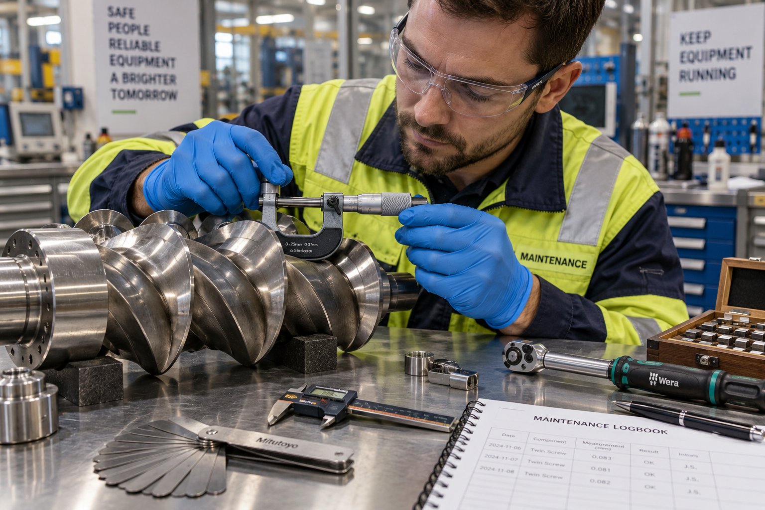
Preventive Maintenance Protocols That Eliminate Recurring Defects
Seasonal drift, screw wear, lubricant migration, stabilizer depletion — every defect mechanism covered in this guide shares one uncomfortable truth: by the time you see the symptom on the extrudate, the root cause has been building for days, weeks, or even months. Reactive troubleshooting fixes the immediate problem, but it does nothing to prevent the same failure from returning on the next shift, the next production run, or the next seasonal transition. Reducing PVC extrusion downtime with preventive maintenance requires a fundamentally different mindset — one that catches degradation before it ever reaches the product.
The gap in most PVC extrusion operations isn't knowledge. Operators understand barrel temperatures, fusion science, and formulation interactions. The gap is structure — a systematic, documented routine that inspects every critical component on a defined schedule, tracks process baselines over time, and flags gradual deterioration while it's still invisible to the naked eye. What follows is that structure, covering the full extrusion line from screw barrel to cutter.
Scheduled Inspection Checklist for the Entire PVC Extrusion Line
A PVC extrusion line preventive maintenance checklist isn't just a list of parts to look at — it's a frequency matrix that matches each component's failure mode to the inspection interval most likely to catch problems early. Some components need a daily glance; others need quarterly measurement with precision instruments. The table below organizes the entire line into a practical PVC extruder screw barrel wear inspection schedule and beyond:
| Component | Daily Check | Weekly Inspection | Monthly Service | Quarterly Overhaul |
|---|---|---|---|---|
| Screw flights | Monitor motor amps and specific rate for drift | Compare output per RPM against baseline | Visual inspection during scheduled shutdowns | Measure flight diameter and clearance with precision gauges |
| Barrel bore | Note any unusual melt temperature variability | Check barrel zone heater response times | Inspect vent ports for buildup or blockage | Measure bore diameter at multiple points; compare to original spec |
| Die and die land | Inspect extrudate surface for progressive streaking or plate-out | Clean die lips; check for buildup deposits | Full die disassembly, cleaning, and polishing of land surfaces | Measure die gap uniformity; inspect for erosion or corrosion |
| Thermocouples | Verify zone readings are stable and consistent | Cross-check barrel readings against handheld pyrometer | Recalibrate or replace any thermocouple showing drift | Full calibration of all barrel, adapter, and die thermocouples |
| Pressure transducers | Confirm melt pressure reading is within baseline range | Check for signal noise or erratic readings | Verify calibration against known reference | Replace diaphragm seals; full recalibration |
| Calibration sleeves | Check vacuum levels and extrudate fit | Inspect sleeve surfaces for scoring, deposits, or wear | Clean and polish sleeve interior; verify dimensional accuracy | Replace worn sleeves; re-qualify vacuum settings |
| Haul-off belts/pads | Listen for slipping; check grip consistency | Inspect belt or pad surfaces for wear, glazing, or contamination | Measure belt tension; adjust or replace worn pads | Full belt replacement if wear exceeds manufacturer spec |
| Cooling system | Verify water temperature and flow rate at calibration and spray tanks | Check for algae, mineral buildup, or flow restrictions | Clean heat exchangers and filters; verify chiller performance | Full system flush; replace worn seals, gaskets, and hoses |
| Cutter | Check cut quality — burrs, deformation, or uneven edges | Inspect blade sharpness and alignment | Sharpen or replace blades; lubricate moving components | Full mechanical inspection of drive, guides, and clamp mechanisms |
You'll notice this matrix covers far more than just the extruder. Calibration sleeves, haul-off belts, and cooling systems degrade just as surely as screws and barrels — they simply fail in different ways. A scored calibration sleeve produces surface marks that mimic die defects. A glazed haul-off belt introduces periodic slip that creates wall thickness variation indistinguishable from surging. A fouled heat exchanger shifts cooling water temperature by a few degrees — enough to cause dimensional drift that operators chase with barrel adjustments, never realizing the real problem is downstream.
The key to making this checklist work in practice is ownership. Assign specific checks to specific roles — daily checks to operators, weekly inspections to shift leads, monthly service to maintenance technicians, and quarterly overhauls to maintenance supervisors or engineers. When everyone assumes someone else is checking the cooling water temperature, nobody checks it.
Tracking Process Baselines to Catch Problems Early
Imagine a blood pressure reading of 145/95. Is that alarming? It depends — alarming compared to what? Without knowing the patient's baseline, a single reading tells you almost nothing. The same principle applies to how to track PVC extrusion process baselines. A melt pressure reading of 185 bar is meaningless in isolation. But if you know that the same product, at the same screw speed, with the same formulation, consistently ran at 165 bar three months ago, that 20-bar increase is a clear signal that something has changed — likely screw wear, die restriction, or a material viscosity shift.
Baseline tracking doesn't require sophisticated process monitoring systems. A simple logbook or spreadsheet recording the following parameters at the start of each production run — when the line is running at optimum conditions and producing good product — provides an enormously powerful diagnostic reference:
- Motor amperage or torque percentage at operating screw speed
- Melt pressure at the adapter
- Melt temperature from the immersion thermocouple
- Output rate (kg/hr) at the operating screw speed
- Specific rate (output divided by screw RPM) — the single most sensitive indicator of screw wear
- All barrel zone set points and actual readings
- Cooling water inlet temperature
- Ambient plant temperature
The power of this data emerges over time. When you plot specific rate week over week, a gradually declining trend reveals screw wear months before it produces visible defects. When motor amps creep upward at the same screw speed, you know melt viscosity is increasing — pointing to a formulation shift, a lubricant imbalance, or a temperature control problem developing. When melt pressure trends upward with stable output, die buildup or screen pack loading is the likely culprit.
A practical trend-tracking method operators can implement immediately: at the start of every Monday production run, record the baseline parameters listed above on a dedicated tracking sheet. Compare each week's values to the previous four weeks. Flag any parameter that has shifted more than 5% from its four-week average. That simple threshold catches gradual degradation reliably without generating false alarms from normal run-to-run variation.
The best troubleshooting is the kind you never have to do. Baseline tracking turns invisible degradation into visible trends — and visible trends get fixed before they become production emergencies.
Building a Proactive Troubleshooting Culture
Structured checklists and baseline tracking are tools. But tools only work when people use them consistently — and that requires a cultural shift from firefighting to prevention. In many PVC extrusion operations, the maintenance team is celebrated for heroic repairs under pressure, while nobody notices the quiet work of preventing those emergencies in the first place. Flipping that equation is where the real operational gains live.
The business case is straightforward. Unplanned downtime on a PVC extrusion line doesn't just cost the hours the line sits idle — it costs startup scrap, requalification time, expedited shipping to meet delayed orders, and the overtime labor to catch up. Industry data shows that product changeovers alone commonly consume 30 to 60 minutes of scrap-generating time, and two changes per day can produce one to two hours of waste. Multiply those losses across unplanned shutdowns caused by preventable failures — a seized bearing, a degraded thermocouple, a worn screw that finally can't hold fusion — and the cost of reactive maintenance dwarfs the investment in prevention.
Preventive maintenance also directly addresses the root causes of long lead times in production. When screw barrels wear beyond their effective service life and the replacement isn't already on site, the line sits idle while procurement scrambles. When a calibration sleeve fails and no spare exists, production waits. Building a spare parts inventory for wear-critical components — and maintaining relationships with suppliers who can deliver replacements on predictable timelines — eliminates these bottlenecks.
For PVC pipe, profile, board, foam board, and WPC extrusion lines that rely on conical twin screw extruders, the screw barrel is the single most wear-critical component in the entire system. Having a reliable supply partner for custom and replacement conical twin screw barrels is not a procurement convenience — it's an essential element of any preventive maintenance strategy. Suppliers like NANHAIYA support this need by engineering application-specific conical twin screw barrels that match the formulation, throughput, and product requirements of each line, ensuring that replacement components restore full process capability rather than introducing new variables.
Practical steps to build a proactive culture include:
- Make baseline data visible. Post trend charts near the extruder so operators see how their line's health is evolving — not just the current shift's output numbers.
- Reward prevention, not just recovery. Recognize the technician who caught a thermocouple drifting before it caused a degradation event, not just the one who stayed late to fix the degradation.
- Conduct brief root cause reviews after every significant defect event. The question isn't just "what went wrong?" — it's "what inspection or measurement would have caught this before it reached the product?" Feed those answers back into the maintenance checklist.
- Schedule major wear component inspections during planned shutdowns rather than waiting for failure. Screw and barrel measurements, die inspections, and calibration sleeve checks are far less expensive during a planned maintenance window than during an emergency that halts production.
PVC extrusion troubleshooting, at its best, is a discipline you practice less and less over time — not because defects stop being possible, but because your inspection routines, baseline data, and preventive maintenance protocols catch the precursors long before they manifest as scrap on the line. The first five minutes after a defect appears matter enormously. But the weeks and months of structured prevention before that defect ever has a chance to appear? That's where operational excellence lives.
Frequently Asked Questions About PVC Extrusion Troubleshooting
1. What are the most common causes of fish eyes in PVC extrusion?
Fish eyes in PVC extrudates result from incomplete gelation, where primary PVC particles survive the extrusion process without fully breaking down and interdiffusing. The most frequent root causes include insufficient compression zone temperatures, excessive external lubricant reducing shear transfer to the compound, low processing aid levels in the formulation, and inadequate screw speed generating too little mechanical energy for particle breakdown. To diagnose, perform an acetone immersion test on a sample — rapid swelling or whitening confirms under-fusion. Corrective steps should follow a structured hierarchy: first verify formulation balance (processing aid and lubricant levels), then adjust compression zone temperature in 3-5 degree C increments, then evaluate a modest screw speed increase to boost shear energy input. Avoid raising temperature alone, as this adds thermal risk without necessarily improving the mechanical breakdown that drives true gelation.
2. How do you tell if PVC extrusion bubbles are caused by moisture or thermal degradation?
Moisture-driven bubbles and degradation-related gas voids look different and behave differently on the production line. Moisture bubbles are typically small, numerous, uniformly distributed through the wall, and feature glossy interior surfaces. They tend to appear more frequently in humid weather or after raw materials have been stored improperly. Degradation voids are larger, more irregular, often elongated along the flow direction, and accompanied by discoloration such as yellowing or browning near the void. A sharp HCl odor at the die exit confirms active thermal decomposition. A simple diagnostic test resolves the question: dry a sample of dry blend at 105 degrees C for two hours and run it at the same settings. If bubbles disappear, moisture was the cause. If they persist, investigate barrel temperatures, stabilizer adequacy, and any dead spots in the flow path where material may be stagnating and overheating.
3. Why does my PVC extrusion line run differently in winter versus summer?
Seasonal ambient temperature swings directly impact PVC processing because the compound enters the feed throat at significantly different temperatures. In winter, dry blend stored in unheated warehouses may arrive 15-20 degrees C colder than during summer, creating a thermal energy deficit the barrel must compensate for. Without feed zone and early compression zone temperature increases, fusion onset is delayed and under-fusion defects such as rough surfaces and poor impact strength appear. In summer, warmer incoming material combined with reduced cooling system efficiency can push melt temperatures past the safe window, risking over-fusion or degradation. Cooling water temperature also shifts seasonally, affecting calibration tank performance and product dimensional accuracy. Maintaining separate parameter sheets for winter and summer operation, and using chillers to stabilize cooling water temperature within a tight band, eliminates most seasonal process drift.
4. How do I know when my PVC extruder screw barrel needs replacement?
Several measurable indicators signal that a conical twin screw barrel has worn beyond its effective service life. The most reliable early sign is declining specific rate — the output in kg/hr divided by screw RPM. If you need progressively higher screw speeds to maintain the same throughput, flight clearance has increased and compression effectiveness has dropped. Additional symptoms include increasing melt temperature variability, surging or pulsating output, rising reject rates despite unchanged settings, and an inability to achieve proper fusion at any temperature combination. Physically, replacement should be evaluated when flight clearance reaches approximately two to four times the original specification. For PVC pipe, profile, and board extrusion, sourcing application-specific replacements from specialists like NANHAIYA ensures the new screw barrel geometry matches your formulation and throughput requirements, restoring full plasticizing capability rather than simply resetting the wear clock.
5. What is the difference between melt fracture and fusion-related surface roughness in PVC extrusion?
These two defects look superficially similar but originate from completely different mechanisms and demand opposite corrective actions. Fusion-related roughness produces a uniform matte, granular texture resembling fine sandpaper. It is present from the very first meter of extrudate, does not worsen over time, and does not respond to die polishing because the defect originates upstream in the barrel where PVC particles failed to fully gel. The fix involves improving fusion through higher compression zone temperatures, increased screw speed, or adjusted processing aid and lubricant levels. Melt fracture, by contrast, produces a repeating patterned distortion — sharkskin ridges or wavy stick-slip marks — caused by excessive shear stress at the die land. It worsens at higher output rates and responds to die-side interventions such as reducing throughput, increasing die temperature, widening the die gap, or adding external lubricant to reduce wall friction. Raising barrel temperature to fix melt fracture risks degradation without addressing the actual shear stress problem at the die.
Written by
Nanhaiya Technical Team
Zhoushan Nanhaiya Plastic Machinery Co., Ltd.
The Nanhaiya technical team supports screw and barrel manufacturing projects through application review, technical communication, custom manufacturing coordination, and production and quality control.
Discuss Your Application
Related Articles
More insights on screw barrel technology and plastics processing.
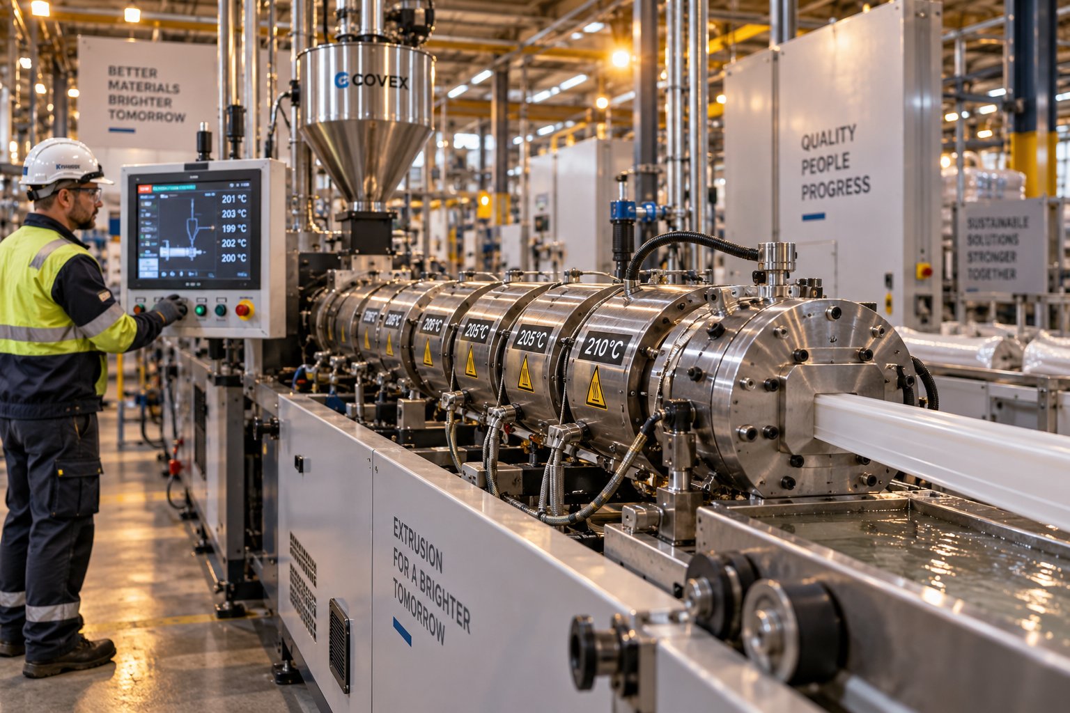
Plastic Extrusion Troubleshooting: Trace Every Defect to Its Source
Oct 16, 2026
Master plastic extrusion troubleshooting with this symptom-first guide. Diagnose defects zone by zone, fix root causes, and prevent recurring issues fast.
Read Article
PVC Profile Extrusion Line Decoded: From Screw Design to Factory Floor
Oct 16, 2026
Learn how a PVC profile extrusion line works — from screw design and barrel profiling to troubleshooting, maintenance, and factory layout planning.
Read Article
WPC Profile Extrusion Machine Decoded: Raw Blend To Flawless Profile
Oct 15, 2026
Learn how a WPC profile extrusion machine works — from extruder types and temperature zones to troubleshooting, wear management, and emerging co-extrusion trends.
Read ArticleLooking for something else?
Search by material, symptom or product and jump straight to the relevant page.
These are navigation suggestions based on keyword matching — not a quotation, not a delivery commitment, and not a substitute for engineering review. Final specification is confirmed by our engineers against your drawings and processed material.
Need help with screw barrel selection?
Share your machine model, processed material and application. Our team can help with pricing and technical support.