

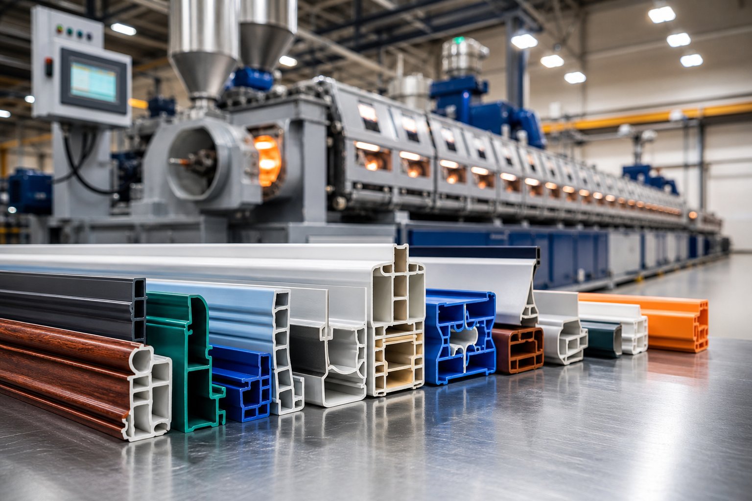
What Is Profile Extrusion and Why Does It Matter
Imagine you need a continuous plastic part - say, a window frame trim or a complex automotive seal - that holds the exact same shape along its entire length. How do you produce thousands of feet of that shape quickly, consistently, and affordably? The answer, for most manufacturers, is profile extrusion.
Defining Profile Extrusion in Plastics Engineering
At its core, profile extrusion is a continuous manufacturing process. Thermoplastic resin is fed into a heated barrel, melted by a rotating screw, and forced through a specially shaped die. The result is a product with a fixed, uniform cross-sectional geometry that can be cut to virtually any length. Unlike injection molding, which produces discrete three-dimensional parts one shot at a time, this process generates an uninterrupted stream of material in a single consistent shape.
Profile extrusion is a continuous plastics manufacturing process in which thermoplastic material is melted, homogenized, and forced through a shaped die to produce parts with a constant cross-sectional geometry - including complex channels, multi-chamber hollows, and custom-designed shapes that go far beyond simple tubes or flat sheets.
That distinction is critical. Sheet extrusion produces flat, uniform-thickness panels. Tube extrusion creates simple round or square hollow sections. Profile extrusions, by contrast, handle the intricate and irregular - think L-channels, multi-cavity window sashes, snap-fit cable ducts, and dual-lipped sealing strips. The cross-section can include varying wall thicknesses, internal chambers, grooves, and fins, all formed in a single pass through the die. This versatility in cross-sectional complexity is exactly what separates this method from its simpler extrusion counterparts.
Why Profile Extrusion Matters for Modern Manufacturing
Few manufacturing processes match the combination of design freedom, production speed, and cost efficiency that profile extrusion delivers. You'll find extruded plastic profiles in virtually every major industry:
- Construction: PVC window frames, door systems, rainwater guttering, and cable conduit
- Automotive: Body side moldings, weatherstripping, bumper trim, and dashboard edge profiles
- Medical: Specialized tubing, device housings, and fluid-handling channels
- Electrical: Wire trunking, LED diffuser housings, and insulation channels
- Consumer goods: Furniture edging, appliance trim, and retail display components
Construction alone represents the single largest market for this technology, with millions of linear feet of extruded PVC profiles installed in buildings worldwide each year. Yet the process is equally indispensable in sectors where tight tolerances and engineered material properties are non-negotiable.
For engineers, the appeal is geometric complexity at production-line speed. For procurement professionals, it is lower tooling costs compared to injection molding and favorable per-unit economics at medium-to-high volumes. For product designers, the ability to specify an extruded plastic profile with custom cross-sections, co-extruded layers, or specialized material blends opens creative possibilities that few other processes can match.
Understanding how this process works - from resin selection through die design to downstream quality control - is essential for anyone specifying, sourcing, or designing plastic components with a constant cross-section. Each stage in the workflow directly influences the dimensional accuracy, surface finish, and mechanical performance of the finished part.
How the Profile Extrusion Process Works Step by Step
A finished extruded profile may look straightforward - a continuous length of plastic with a fixed shape - but the journey from raw pellet to precision part involves a tightly coordinated sequence of thermal, mechanical, and dimensional control steps. Each stage in the plastic profile extrusion process directly shapes the quality, accuracy, and surface finish of the final product. Here is exactly what happens inside a profile extruder, stage by stage.
From Raw Pellets to Molten Polymer
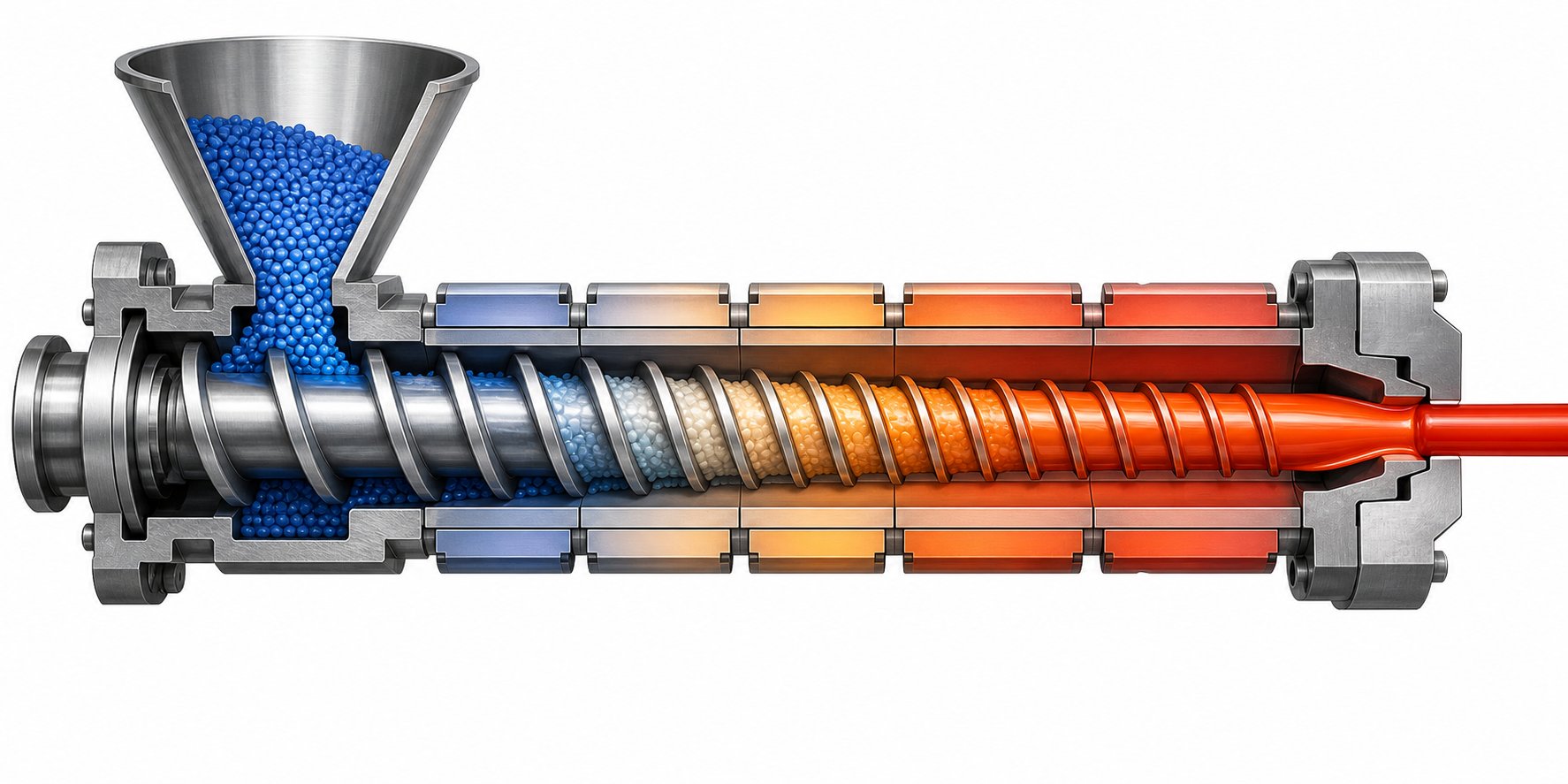
Every production run begins at the hopper, a funnel-shaped container mounted above the extruder barrel. Thermoplastic pellets or granules - sometimes blended with colorants, stabilizers, or processing aids - are gravity-fed from the hopper into the barrel's feed throat. From this point, a rotating screw takes over.
Picture the screw as the engine of the entire plastic profile extrusion machine. As it turns inside the heated barrel, it performs three distinct functions across three carefully engineered zones:
- Feed zone: The screw's deep flights pick up solid pellets from the hopper and convey them forward. Here, the channel depth is at its greatest, allowing material to enter freely without premature compression.
- Compression (transition) zone: The flight depth gradually decreases, compacting the softening pellets against the barrel wall. This compression generates shear heat and eliminates air pockets trapped between granules. The material transitions from solid to a semi-molten state.
- Metering zone: The shallowest section of the screw delivers a fully molten, homogenized polymer at consistent pressure and temperature to the die. Uniform output here is critical - any fluctuation in pressure or melt quality shows up as dimensional variation in the finished profile.
Temperature control across the barrel is equally important. The barrel is divided into multiple heating zones, each regulated independently through electric heater bands and cooling fans. Temperatures typically ramp upward from the feed throat toward the die end, though the exact profile depends on the resin being processed. Overheating degrades the polymer, while insufficient heat leaves unmelted particles that create surface defects. For PVC processing, counter-rotating conical or parallel twin-screw extruders are commonly used, whereas polyolefins and engineering thermoplastics typically run on single-screw machines with length-to-diameter (L/D) ratios between 24:1 and 33:1.
Screw geometry - flight depth, pitch, compression ratio, and the presence of mixing elements - must be matched to the specific resin. A screw designed for HDPE will not deliver optimal melt quality if swapped in for a rigid PVC compound, because each polymer has different melting behavior, viscosity, and shear sensitivity.
Die Shaping and Downstream Processing
The molten polymer, now pressurized and uniform, exits the barrel and enters the extrusion die. This is where the material takes its intended cross-sectional shape. The die's internal flow channels guide the melt into the target geometry - whether that is a simple U-channel, a multi-chamber window sash, or a snap-fit cable duct. Getting an even flow distribution across the die opening is essential; imbalanced flow leads to warping, uneven wall thickness, or surface irregularities.
What emerges from the die is a hot, soft extrudate that still needs to be cooled, sized, and stabilized before it becomes a usable part. The downstream processing stages handle exactly that, and each one has a measurable impact on final part quality.
- Material feeding - Pellets enter the hopper and are metered into the barrel at a controlled rate.
- Melting and homogenization in the screw barrel - The rotating screw conveys, compresses, and melts the resin across its three functional zones, producing a uniform polymer melt.
- Die forming - The pressurized melt is pushed through the shaped die, creating the desired cross-sectional profile.
- Calibration and sizing - The soft extrudate enters a vacuum or pressure calibration unit that holds it against a precisely machined sleeve, locking in the target dimensions before the material can distort.
- Cooling - The profile passes through a water bath or spray cooling tank, solidifying the shape completely. Gradual, uniform cooling minimizes internal stress and prevents warping.
- Haul-off and cutting - A haul-off unit grips the cooled profile and pulls it at a constant speed synchronized with the extruder output. A downstream cutter then slices the continuous length into specified pieces. Haul-off speed directly affects wall thickness - pulling faster thins the profile, while slowing it down adds thickness.
- Quality inspection - Finished profiles are checked for dimensional accuracy, surface finish, color consistency, and mechanical properties before packaging or secondary processing.
The calibration stage deserves special attention. Inside the calibrator, vacuum pressure draws the still-pliable extrudate outward against a metal sizing sleeve, effectively freezing the profile at the correct dimensions. Without precise calibration, even a perfectly designed die cannot guarantee tight tolerances on the finished part. Cooling must also be carefully managed - if the profile cools unevenly, residual stress builds up, leading to bowing, twisting, or dimensional drift over time.
Every component in this chain - from screw design through die geometry to haul-off speed control - functions as part of an interconnected system. A plastic profile extruder is only as good as the weakest link in its downstream line. Adjusting one variable, such as screw speed, requires compensating adjustments in temperature zones, haul-off rate, and cooling intensity to maintain dimensional consistency.
Of course, all of this engineering effort hinges on one foundational decision made before the first pellet ever enters the hopper: which thermoplastic material to run. That choice influences every parameter discussed here - from screw geometry and barrel temperatures to die design and cooling rates - and it is far more consequential than many first-time specifiers realize.
Materials Used in Plastic Profile Extrusion
Choosing a thermoplastic for your profile project is not a minor detail - it is the single decision that ripples through every downstream engineering choice. The resin you select dictates barrel temperatures, screw geometry, die flow channel design, cooling rates, and even the type of calibration unit required. Get it right, and the entire line runs smoothly. Get it wrong, and you'll fight dimensional drift, surface defects, and premature part failure from day one.
So what are the real options? The world of profile plastics spans everything from low-cost commodity resins to specialty engineering polymers built for extreme environments. Understanding how each material behaves - both in the melt phase and in the finished product - is essential for engineers, designers, and procurement teams evaluating plastic extrusion profiles for any application.
PVC and Its Dominance in Profile Extrusion
If one material dominates the profile extrusion landscape, it is polyvinyl chloride. PVC accounts for a larger share of extruded profiles worldwide than any other thermoplastic, and the reasons are deeply practical rather than accidental.
Consider what PVC offers in a single package:
- Cost-effectiveness: Raw PVC resin is among the least expensive engineering-capable thermoplastics available, keeping per-meter production costs low even for complex multi-chamber profiles.
- Weatherability: Rigid PVC resists UV degradation, moisture absorption, and atmospheric pollutants, making it a natural fit for outdoor construction products that must endure decades of exposure.
- Inherent flame retardance: Unlike polyolefins, PVC contains chlorine in its molecular backbone, giving it a naturally high limiting oxygen index. It self-extinguishes when the flame source is removed - a critical advantage for building code compliance.
- Processing versatility: Both rigid (uPVC) and flexible (plasticized) formulations extrude well, with processing temperatures typically ranging from 320 degF to 400 degF (160 degC to 205 degC). The relatively low melt temperature reduces energy consumption compared to engineering resins.
You'll find extruded PVC profiles in window and door frames, cable trunking, edge banding, rainwater guttering, PVC fencing, and electrical conduit. Construction alone absorbs the majority of global PVC profile output, with window systems representing the single highest-volume application. The material's dimensional stability, colorability, and weldability (PVC profiles can be fusion-welded at corners without adhesives) make pvc extrusion profiles a default specification across the building products sector.
Flexible PVC compounds, meanwhile, serve applications requiring elasticity - think refrigerator door gaskets, decorative trim with soft edges, and protective cable sleeving. By adjusting the plasticizer content, formulators can tune shore hardness from semi-rigid down to highly flexible within the same polymer family.
Engineering Thermoplastics for Demanding Applications
PVC covers an enormous range of use cases, but it is not the right answer for every project. When you need higher impact resistance, elevated service temperatures, superior chemical resistance, or specific mechanical properties, engineering and commodity thermoplastics step in to fill the gap. Each brings its own processing characteristics - and its own challenges on the extrusion line.
ABS (Acrylonitrile Butadiene Styrene) delivers excellent impact resistance and a high-quality surface finish that can be painted, plated, or textured. Its amorphous structure resists shrinkage, which simplifies die design and calibration. ABS is commonly extruded into appliance trim, automotive interior profiles, and consumer electronics housings.
Polycarbonate (PC) stands out for optical clarity, high impact strength, and an operating temperature range that extends well above what PVC or ABS can handle. It is the go-to choice for transparent or translucent profiles such as LED lighting diffuser covers and protective equipment housings. However, polycarbonate's higher melt viscosity and processing temperature (around 500 degF to 570 degF) demand robust barrel heating capacity and carefully optimized die flow channels.
HDPE (High-Density Polyethylene) is a crystalline polymer prized for its chemical resistance, moisture impermeability, and toughness at low temperatures. HDPE profiles appear in outdoor decking support channels, chemical-resistant cable trays, and playground equipment components. Its relatively high shrinkage rate - a characteristic of crystalline polymers - requires dies designed with generous oversize compensation and careful downstream cooling control.
Polypropylene (PP) shares many of HDPE's advantages while offering a higher melting point and better rigidity. Automotive underbody trim, reusable container edges, and chemical tank profiles frequently use PP. Like HDPE, its crystalline nature means managing shrinkage is a core die design consideration.
TPE (Thermoplastic Elastomers) bridge the gap between rigid plastics and rubber. TPE profiles are soft, flexible, and return to their original shape after deformation - ideal for sealing strips, vibration dampening profiles, and grip surfaces. Many TPE formulations bond well to rigid substrates during co-extrusion, enabling dual-durometer designs.
Nylon (Polyamide) excels where abrasion resistance, mechanical strength, and high-temperature performance are non-negotiable. Extruded nylon profiles serve in conveyor system guides, wear strips, and industrial brush channels. Nylon's hygroscopic nature - it absorbs moisture from the air - means the resin must be thoroughly dried before processing, or moisture-related defects like bubbles and surface splay will appear in the extrudate.
Each material's melt behavior directly drives the engineering of every component upstream and downstream of the die. A plastic PVC extrusion profile runs at moderate temperatures with relatively forgiving flow characteristics, while a polycarbonate profile demands significantly higher thermal input and tighter process control. The table below gives you a quick-reference comparison.
| Material | Typical Processing Temperature Range | Key Properties | Common Profile Applications |
|---|---|---|---|
| PVC (Rigid) | 320 - 400 degF (160 - 205 degC) | Flame retardant, weatherable, cost-effective, dimensionally stable | Window frames, cable trunking, edge banding, conduit |
| PVC (Flexible) | 300 - 380 degF (150 - 195 degC) | Elastic, soft-touch, tunable hardness via plasticizer content | Gaskets, protective sleeving, decorative trim |
| ABS | 400 - 475 degF (205 - 245 degC) | High impact resistance, excellent surface finish, low shrinkage | Appliance trim, automotive interiors, electronics housings |
| Polycarbonate | 500 - 570 degF (260 - 300 degC) | Optical clarity, outstanding impact strength, high heat resistance | LED diffusers, protective covers, transparent profiles |
| HDPE | 400 - 530 degF (205 - 275 degC) | Chemical resistance, moisture-proof, tough at low temperatures | Decking supports, cable trays, outdoor profiles |
| Polypropylene | 400 - 480 degF (205 - 250 degC) | Good rigidity, chemical resistance, higher melting point than PE | Automotive trim, container edges, chemical tank profiles |
| TPE | 350 - 450 degF (175 - 230 degC) | Rubber-like flexibility, elastic recovery, bonds well in co-extrusion | Sealing strips, grip surfaces, vibration dampening profiles |
| Nylon (PA) | 450 - 530 degF (230 - 275 degC) | Abrasion resistant, high strength, excellent high-temperature performance | Wear strips, conveyor guides, industrial channels |
A few patterns stand out. Amorphous plastics like PVC, ABS, and polycarbonate tend to exhibit lower and more predictable shrinkage, which simplifies tooling design. Crystalline and semi-crystalline materials such as HDPE, polypropylene, and nylon shrink more aggressively and unevenly, demanding dies that are cut oversize and cooling systems calibrated to manage differential solidification rates.
Material selection, in short, is never an isolated decision. The resin you choose must be coordinated with die geometry, screw and barrel configuration, calibration setup, and cooling strategy to deliver optimal output quality. A mismatch between material and processing equipment is one of the most common root causes of poor surface finish, dimensional inconsistency, and excessive scrap rates on a profile line.
Yet even when the material is perfectly matched to the extruder, the final quality of a plastic profile ultimately depends on the one component that physically shapes the melt into a usable product - the extrusion die itself. Its internal geometry, surface finish, and flow balancing determine whether the resin's inherent properties translate into a precision part or a reject.
Die Design and Tooling for Custom Profiles
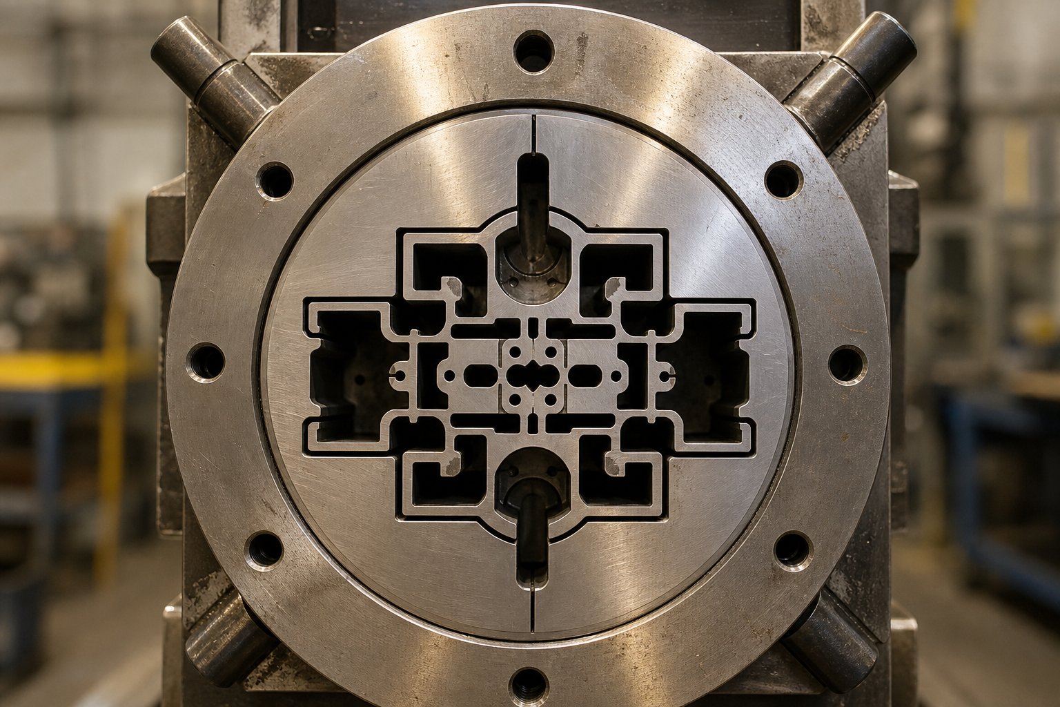
The extrusion die is where engineering ambition meets physical reality. Every feature you see in a finished profile - each groove, channel, hollow chamber, and snap-fit lip - was first carved into a block of hardened steel and then refined through iterative testing until the extrudate matched the target geometry. No other single component in a profile extrusion line has a greater impact on product quality, dimensional consistency, and production efficiency. And yet, die design remains one of the least discussed aspects of the process.
Why is it so challenging? As extrusion engineering consultant Chris Rauwendaal explains, the size and shape of the extruded product varies from that of the die flow channel because multiple mechanisms - die swell, draw down, and cooling shrinkage - simultaneously alter the extrudate after it leaves the die. Predicting how those forces interact for a given profile geometry and resin is what makes custom plastic profile extrusion one of the most demanding specialties in plastics engineering.
How Custom Profile Dies Are Engineered
Imagine you need an L-shaped channel with one thick wall and one thin wall, plus a small internal fin. The die designer does not simply cut that exact shape into a steel plate. Instead, the process works backward from the desired finished cross-section, compensating at every step for the physics that will alter the extrudate between the die exit and the haul-off unit.
Three major phenomena drive those compensations:
- Die swell (extrudate swell): Elastic recovery in the polymer causes the extrudate to expand as it exits the die opening. The die aperture must be undersized relative to the target profile to account for this expansion. The degree of swell varies by resin - polycarbonate, for instance, can shift its die-swell ratio by up to 18% across its processing window.
- Material shrinkage: As the profile cools from melt temperature to ambient, it contracts. Semi-crystalline resins like HDPE and polypropylene shrink more aggressively than amorphous materials like PVC or ABS, so the die must be cut proportionally larger to hit final dimensions.
- Draw down: The haul-off pulls the extrudate faster than it exits the die, thinning and elongating the profile. In non-circular cross-sections, draw down also changes the shape because material in corners flows more slowly, causing corner regions to thin disproportionately. A square die opening, for example, typically produces a bulged product rather than a true square.
Flow balancing is where the real artistry enters. When a profile has non-uniform wall thickness - and most custom extruded plastic profiles do - thicker sections allow the melt to flow faster than thin sections. Left uncorrected, this imbalance causes distortion, warping, and uneven surface finish. Die engineers address this through two primary techniques:
Land length adjustment. The land is the final parallel section of the die channel just before the exit. By making the land longer in thick-walled zones, the designer increases flow resistance there, slowing it to match the velocity through thinner regions. The required land length ratio follows a power-law relationship based on the channel height ratio and the polymer's power law index. For most polymers, a channel that is 5 mm high needs a land roughly 2.15 times longer than a 3 mm channel to produce balanced flow.
Channel height modification. In profiles with thick features like ribs or circular sections, the die designer can insert pins or restrictors to reduce the effective channel height in those areas, forcing the melt velocity toward uniformity. This approach works well where land length adjustment alone cannot eliminate cross-flow between thick and thin zones.
Several general rules guide the overall channel geometry. There should be no dead spots in the flow path - stagnant zones degrade the polymer and create surface defects. Velocity should increase steadily along the channel. And abrupt changes in cross-section are avoided because they generate turbulence and inconsistent melt delivery.
Tooling Considerations for Complex Profiles
Solid profiles are relatively straightforward to tool. Hollow profiles are a different story. Creating an internal void requires a mandrel - a metal core that sits inside the melt stream and forms the inner wall of the profile. The mandrel must be supported without disrupting flow, which is where spider dies come in. Spider dies use thin metal legs radiating inward to hold the mandrel centered, but the melt stream splits around each leg and must recombine downstream. Those recombination zones create weld lines that can reduce mechanical strength if not carefully managed through temperature optimization and adequate post-spider flow path length.
For projects requiring multiple identical profiles from a single die, multi-cavity dies allow several cross-sections to be extruded simultaneously. Each cavity must be independently flow-balanced, which adds significant design complexity but dramatically increases throughput for high-volume profile custom extrusions.
Die material and surface treatment also play critical roles in both longevity and part quality. Most custom profile extrusion dies are machined from H13 or comparable hardened tool steel, chosen for its thermal conductivity, wear resistance, and toughness under sustained high-pressure operation. Surface treatments like nitriding, chrome plating, or hard coating reduce friction between the polymer melt and the die walls, improving the profile's surface finish while extending die service life. For PVC processing specifically, corrosion-resistant steel grades or specialized coatings are essential, because PVC releases hydrogen chloride gas during extrusion that aggressively attacks standard tool steels.
The iterative nature of die development deserves emphasis. Even with advanced CAD modeling and finite element analysis simulations, most custom plastic profiles require at least one - and often several - trial runs with die geometry adjustments before target tolerances are achieved. Manufacturers with in-house die machining capabilities can iterate in days rather than weeks, which is a meaningful advantage when project timelines are tight.
When evaluating any custom profile extrusion project, the following factors must be addressed during die design:
- Target profile geometry, including wall thickness variations and internal features
- Material rheology - melt viscosity, die swell behavior, and shrinkage characteristics
- Production speed requirements and their effect on flow balance
- Tolerance specifications for critical dimensions
- Surface finish standards and any aesthetic requirements
Each of these variables interacts with the others. A tighter tolerance spec may demand a slower production speed to maintain dimensional control. A profile with extreme wall thickness variation requires more sophisticated flow balancing - possibly including internal partitions within the die to prevent cross-flow between thick and thin zones. And a switch from PVC to polycarbonate on the same basic profile shape can require a completely redesigned die due to the difference in melt behavior.
Die engineering, in short, is the bridge between a profile design on a CAD screen and a physical part you can hold in your hand. The quality of that bridge determines whether the final product meets spec on the first run or requires costly rework. Yet even the most precisely engineered single-material die reaches its limits when a project calls for combining two or more materials - a rigid core with a flexible seal, or a weatherable cap over a cost-effective substrate - within a single continuous profile. That challenge belongs to co-extrusion, a technique that multiplies both the possibilities and the engineering complexity of the process.
Co-Extrusion and Multi-Material Profile Techniques
What if a single material simply cannot deliver everything your profile needs? A window frame requires structural rigidity in its core but a UV-resistant color layer on the exterior. An automotive weatherseal demands a rigid mounting clip fused to a soft, compressible sealing lip. A medical catheter needs a lubricious inner bore bonded to a tough outer shell. No single polymer checks all those boxes simultaneously - and that is precisely the problem co-extrusion solves.
Co-extrusion is a process in which two or more polymers are extruded simultaneously and joined within a single die to form a unified, multi-material profile in one continuous operation. Rather than manufacturing separate components and assembling them later, this technique produces a finished coextrusion profile directly off the line - with distinct material zones permanently bonded at the molecular level during forming.
How Co-Extrusion Produces Multi-Material Profiles
Picture two or three separate extruders, each melting a different resin, all feeding into a shared die head. Inside that die, dedicated flow channels keep the individual melt streams separated until they converge at or near the die exit. At the merge point, the hot polymer layers bond together under pressure before entering the calibration unit as a single integrated extrudate.
The setup looks more complex than a standard single-material line, but the principle is straightforward: each extruder handles one material independently - controlling its own barrel temperatures, screw speed, and melt pressure - while the die geometry determines where each material ends up in the finished cross-section. The result is a profile that combines properties impossible to achieve with any single resin.
Why go to this trouble? Co extrusions eliminate secondary assembly steps, reduce adhesive failures, and deliver material properties exactly where they are needed most. Common strategies include:
- Cap layering: A thin, weather-resistant or colored outer layer over a cost-effective structural substrate - widely used in PVC window profiles where an acrylic or ASA cap provides superior UV resistance without the expense of making the entire frame from premium resin.
- Soft-over-hard combinations: A rigid structural body with a flexible sealing edge or grip surface extruded as one piece, eliminating the need for mechanical fastening or post-applied adhesives.
- Barrier layering: Multiple polymer layers stacked to block gas permeation, moisture transmission, or chemical migration - critical in medical and food-contact tubing applications.
Dual Durometer and Multi-Layer Profile Applications
Among the most commercially significant co-extrusion applications is the dual durometer profile - a part that combines two materials of different hardness (durometer) bonded during extrusion into a single functional component. You encounter these every time you close a car door.
Automotive weatherstripping is a textbook example. The rigid clip section - typically extruded from polypropylene or a hard TPE compound - snaps onto the vehicle's sheet metal flange and provides structural retention. The sealing bulb, co-extruded from a soft, compressible TPE or EPDM-like compound, deforms against the door frame to create a watertight and noise-reducing seal. Manufacturing these as a single coextruded profile eliminates the weak bond line that would exist if two separately made pieces were glued together.
Other real-world applications span multiple industries:
- Window systems: Rigid PVC frames with co-extruded soft gasket lips and color-matched exterior cap layers
- Medical tubing: Multi-layer catheter shafts combining a lubricious inner layer (such as HDPE) with a bondable outer layer (such as PEBA) and an adhesive tie layer between them - with individual wall thicknesses as thin as 25 microns
- Construction trim: Economical recycled-content cores capped with virgin material for appearance and weather performance
- Consumer products: Tool grips, appliance seals, and furniture edging combining structural support with soft-touch surfaces
The technical challenges, however, are substantial. Successful co-extrusion demands that engineers carefully manage several interacting variables:
Melt temperature compatibility. The polymers being combined must have overlapping or closely matched processing temperature windows. If one material requires 500 degF and another degrades above 380 degF, they cannot be co-extruded without an intermediate tie layer or a die design that minimizes thermal cross-contamination between flow channels.
Interlayer adhesion. Not all polymers bond naturally to each other. Materials with low surface energies - like polyethylene and nylon - will delaminate unless an adhesive tie layer is introduced between them. Die designers must account for this additional melt stream, which adds another extruder and another set of flow channels to the system.
Differential shrinkage. When two co-extruded materials shrink at different rates during cooling, internal stresses build at the interface. Left unmanaged, this leads to warping, curling, or eventual delamination in the finished profile. Matching materials with compatible shrinkage characteristics - or designing the profile geometry to accommodate differential contraction - is essential for long-term performance.
Flow velocity matching. At the point where melt streams merge inside the die, velocity differences between layers create wave-like instabilities at the interface. These instabilities cause intermixing, poor aesthetics, and reduced mechanical performance. Die flow channels are engineered using computational fluid dynamics to ensure each polymer stream arrives at the merge point with matched velocities.
Viscosity management ties all of these challenges together. When materials with different viscosities meet inside a die, the lower-viscosity melt tends to migrate toward the outer walls of the flow channel, encapsulating the higher-viscosity material and disrupting layer uniformity. Best practice positions the highest-viscosity polymer on the inside and the lowest-viscosity material on the outside, where it naturally wants to flow.
Despite this complexity, co-extrusion continues to grow because it delivers something no post-assembly method can replicate: a molecularly bonded, multi-functional profile produced at line speed with zero secondary operations. For engineers and product designers evaluating whether their next project warrants a dual durometer or multi-layer approach, the key question is simple - does the application demand different performance properties in different zones of the same cross-section? If so, co-extrusion is almost certainly the most efficient path to that result.
With the manufacturing techniques themselves well established - from single-material dies through multi-extruder co-extrusion setups - the broader question becomes where these profiles actually end up. The range of industries relying on extruded profiles is far wider than most newcomers expect, and the performance requirements vary dramatically from one sector to the next.
Profile Extrusion Applications Across Key Industries
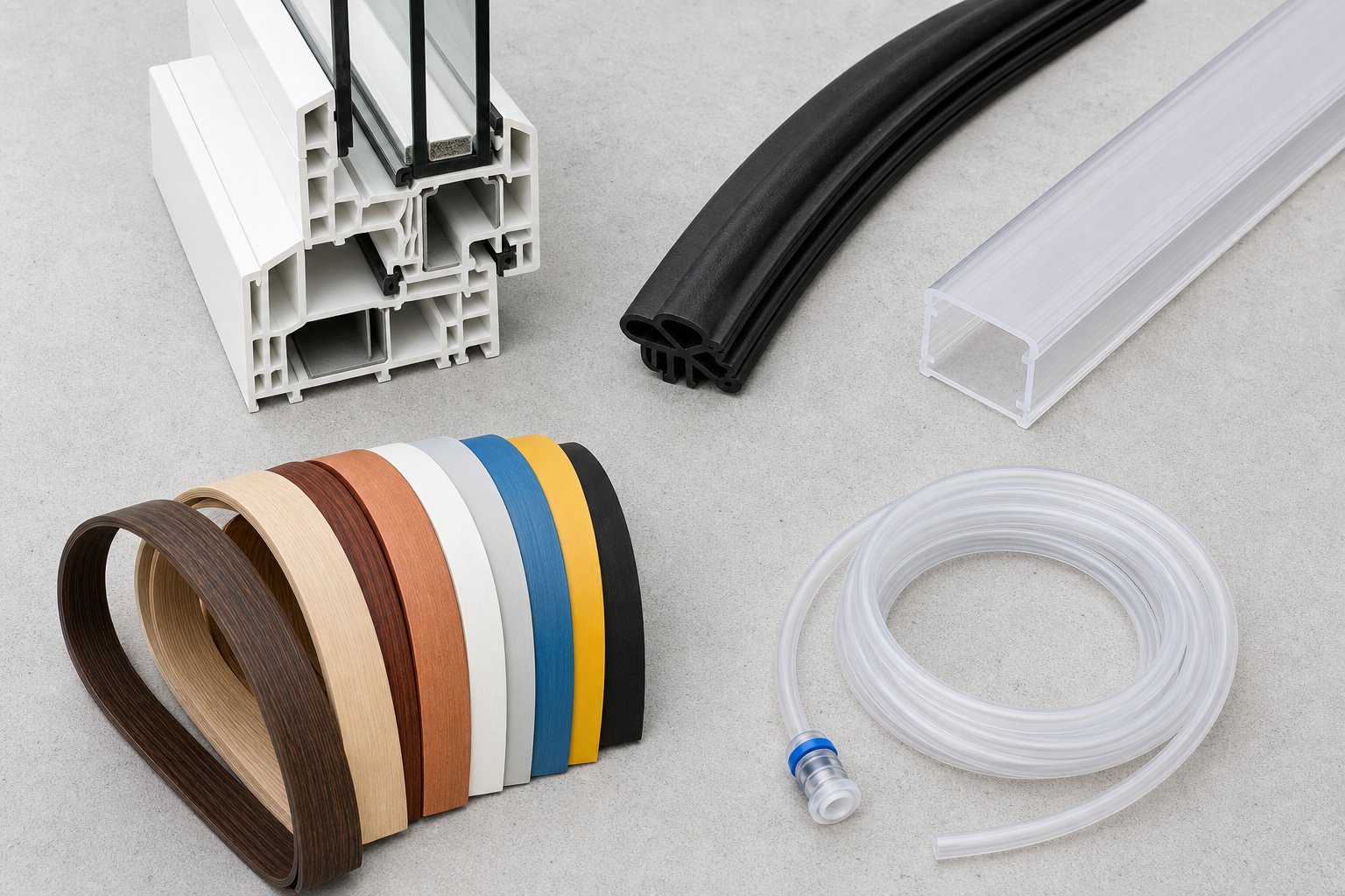
A process this versatile does not serve a single market - it threads through virtually every sector that uses continuous-length plastic components. Yet lumping all applications into a generic list does a disservice to the engineering specificity involved. A PVC window frame and an automotive bumper trim may both be extruded plastic profiles, but the materials, tolerances, and performance standards behind each are worlds apart. Breaking applications down by industry reveals both the breadth of the technology and the distinct demands each sector places on the extrusion process.
Construction and Building Products
Construction is the undisputed heavyweight. The sector alone accounted for more than 36% of total extruded plastics demand in 2025, making it the single largest end market for plastic profile extrusions worldwide. The reasons are straightforward: buildings need millions of linear feet of consistently shaped components that resist weather, insects, rot, and UV exposure - all at a price point that keeps project budgets viable.
Specific profiles you will find across residential and commercial construction include:
- Window and door frames: Multi-chamber rigid PVC profiles engineered for thermal insulation, structural rigidity, and decades of outdoor exposure without painting or sealing
- Siding trim and cladding: Decorative and protective profiles that cap building exteriors, resist impact damage, and maintain color stability
- Cable conduit and trunking: Channels that route electrical wiring safely through walls and ceilings while meeting fire-rating standards
- Decking profiles: Wood-plastic composite (WPC) boards and support rails offering the appearance of timber without rotting, splintering, or requiring annual maintenance
- Rainwater guttering: PVC and HDPE gutter sections and downpipe profiles molded for water flow efficiency and snap-fit jointing
- PVC fencing: Hollow and solid profiles that replicate the appearance of painted wood while eliminating ongoing upkeep
Global construction output exceeded $13 trillion in 2025, and projections point toward $17 trillion by 2030. That expansion, coupled with ongoing replacement of aging metallic and wooden infrastructure with corrosion-resistant polymer alternatives, means demand for construction-grade plastic extruded profiles continues to grow at rates above the general market average - particularly across Asia Pacific, the Middle East, and Latin America where urbanization and affordable housing programs are generating enormous volumes of new building starts.
Automotive, Electrical, and Consumer Applications
Beyond construction, the automotive sector is rapidly scaling its consumption of extruded profiles. Battery electric vehicle platforms require an estimated 8-12 kg of additional extruded plastic content per vehicle compared to conventional internal combustion models, driven by the need to cut weight and extend driving range. With global BEV production surpassing 16 million units in 2025 and projected to exceed 45 million annually by 2034, the automotive addressable market for plastic extrusion shapes is nearly tripling within a single decade.
Typical automotive profiles include body side moldings that protect painted surfaces from parking lot dings, flexible bumper trim that absorbs minor impacts, co-extruded weatherseals combining rigid clips with soft sealing bulbs, and dashboard edge profiles that provide a finished appearance while hiding panel joints. Materials range from TPE and EPDM-like compounds for seals to polypropylene, ABS, and polycarbonate for rigid trim elements.
Electrical applications depend heavily on flame-rated plastic extrusion shapes for cable management. Cable trunking systems - those rectangular channels running along office walls or inside industrial enclosures - are almost universally produced through profile extrusion in rigid PVC or halogen-free formulations. LED lighting diffuser housings, another fast-growing application, use polycarbonate or acrylic profiles to distribute light evenly while protecting the LED strip beneath. Wire insulation channels and panel-mounted connector housings round out the electrical category.
Consumer goods represent a quieter but substantial market. Furniture edging in ABS or PVC covers raw panel edges with a clean, durable finish. Retail display channels hold price tags and signage in supermarkets and showrooms. Appliance trim profiles edge refrigerator doors, washing machine panels, and air conditioning units. Many manufacturers of household and retail products rely on suppliers of custom plastic profiles and extrusions to deliver exactly the cross-section they need - in the right color, material, and tolerance - without the tooling cost of injection molding.
The table below organizes these applications into a quick-reference format for engineers and procurement professionals evaluating whether profile extrusion suits a specific project.
| Industry Sector | Example Profiles | Typical Materials Used | Key Performance Requirements |
|---|---|---|---|
| Construction | Window frames, door systems, cable conduit, decking, guttering, fencing | Rigid PVC, HDPE, WPC (wood-plastic composite) | UV resistance, flame retardance, thermal insulation, 25+ year service life |
| Automotive | Body side moldings, bumper trim, weatherseals, dashboard edge profiles | TPE, polypropylene, ABS, polycarbonate | Impact absorption, flexibility, color stability, temperature cycling resistance |
| Electrical | Cable trunking, wire channels, LED diffuser housings, connector profiles | Rigid PVC, halogen-free compounds, polycarbonate, acrylic | Flame rating (UL94), dielectric strength, light diffusion efficiency |
| Consumer Goods | Furniture edging, retail display channels, appliance trim, protective bumpers | ABS, PVC, polypropylene, TPE | Surface finish quality, color matching, snap-fit precision, cost efficiency |
| Medical | Catheter shafts, fluid-handling channels, device housings, tubing profiles | PEBA, HDPE, polycarbonate, nylon | Biocompatibility, dimensional precision, sterilization resistance, multi-layer bonding |
What this cross-industry view makes clear is that profile extrusion is not a one-size-fits-all technology - it is a platform process whose output characteristics change dramatically depending on the materials, tooling, and quality standards specified for each sector. A construction window profile tolerates dimensional variation of plus or minus 0.3 mm comfortably, while a medical catheter profile may demand tolerances tighter than plus or minus 0.05 mm. Both are extruded profiles, but they represent entirely different levels of process control.
That raises an important question for anyone evaluating their manufacturing options: when is profile extrusion actually the right choice compared to injection molding, pultrusion, or even additive manufacturing? The answer depends on part geometry, production volume, and budget - factors that deserve a direct, side-by-side comparison.
Profile Extrusion vs. Other Manufacturing Methods
You have a part with a constant cross-section, a target material, and a production volume in mind. Does that automatically mean extrusion profiles are the answer? Not necessarily. Several competing technologies can produce plastic parts with fixed or near-fixed geometries, and each comes with its own cost structure, design envelope, and volume sweet spot. Choosing the wrong method can mean overpaying for tooling, underperforming on mechanical properties, or locking yourself into a process that cannot scale. A clear, side-by-side comparison eliminates guesswork.
Profile Extrusion vs. Injection Molding and Pultrusion
The most common alternative engineers consider is injection molding - and the distinction is fundamental. Injection molding fills a closed cavity to produce discrete, three-dimensionally complex parts one cycle at a time. Profile extrusion, by contrast, generates continuous lengths of uniform cross-section at production-line speed. If your part is a bracket, a housing, or a snap-fit connector with geometry that changes in all three axes, injection molding is the right tool. If your part is a channel, trim, seal, or frame that maintains the same shape along its length, extruded profiles are almost always more efficient.
Tooling economics reinforce this divide. A custom injection mold - machined from hardened steel with internal cooling channels, ejector systems, and precision parting lines - typically costs several times more than an extrusion die of comparable complexity. That gap matters enormously at moderate production volumes. For a simple extruded profile, die tooling might run a few thousand dollars, whereas an injection mold for a part of similar material volume could easily reach tens of thousands. This lower tooling threshold makes extrusions and profiles viable even for mid-volume projects where injection molding would be prohibitively expensive per unit.
Pultrusion enters the picture when you need fiber reinforcement. While standard profile extrusion pushes thermoplastic melt through a die, pultrusion pulls continuous reinforcing fibers - glass, carbon, or Kevlar - through a resin-impregnation system and a heated forming die. The result is a composite profile with exceptional tensile strength and stiffness-to-weight ratio. Pultruded fiberglass rods, for instance, can deliver roughly three times the tensile strength of extruded 6063 aluminum at significantly lower weight. The tradeoff is reduced design flexibility - pultrusion handles simpler cross-sections - and limited material options, since the process is built around thermoset resins rather than thermoplastics.
3D printing (additive manufacturing) occupies yet another niche. It excels at rapid prototyping, one-off geometries, and parts too complex for any die-based process. However, it cannot match the throughput, surface finish, or per-unit plastic extrusion cost of a running extrusion line. For production quantities above a few hundred parts, 3D printing is rarely competitive on economics alone.
When Profile Extrusion Is the Most Cost-Effective Choice
Rather than defaulting to any single method, consider four decision factors that consistently determine the best fit:
- Part geometry: Does the part maintain a constant cross-section along its length? If yes, extrusion is the natural frontrunner. Variable 3D geometry points toward injection molding or additive manufacturing.
- Production volume: Medium-to-high volumes - hundreds to millions of linear feet - drive per-unit cost down dramatically on an extrusion line. Low volumes of complex 3D parts favor injection molding (if tooling budget allows) or 3D printing (if quantities are small).
- Material requirements: Standard thermoplastics and co-extruded multi-material combinations are squarely in the extrusion wheelhouse. Fiber-reinforced composites steer the decision toward pultrusion. Highly filled engineering resins requiring precise three-dimensional features lean toward injection molding.
- Budget: Lower tooling investment for extrusion dies means faster breakeven. If a project demands high volumes of extruded profiles but tooling budget is constrained, extrusion offers the shortest path to positive unit economics.
The table below puts these factors side by side for a quick comparison.
| Manufacturing Method | Best For | Tooling Cost (Relative) | Ideal Volume | Material Options |
|---|---|---|---|---|
| Profile Extrusion | Continuous parts with constant cross-section | Low to Medium | Medium to High (hundreds to millions of linear feet) | Wide range of thermoplastics; multi-material via co-extrusion |
| Injection Molding | Discrete, 3D-complex parts | High | High (thousands to millions of units) | Broadest thermoplastic and thermoset range |
| Pultrusion | Fiber-reinforced structural profiles | Medium | Medium to High | Thermoset resins with glass, carbon, or aramid fibers |
| 3D Printing | Prototypes, one-offs, extreme geometric complexity | None (no tooling) | Very Low (1 to hundreds of parts) | Growing but limited versus molding or extrusion |
A few patterns emerge from this comparison. Profile extrusion occupies a unique position: it delivers lower tooling costs than injection molding, broader thermoplastic compatibility than pultrusion, and vastly higher throughput than 3D printing. For any project requiring consistent cross-sectional geometry in a thermoplastic material at meaningful production volumes, it is difficult to beat on overall plastic extrusion cost per unit.
That said, choosing the right process is only half the equation. Even a perfectly selected method delivers subpar results if the finished parts are not measured, verified, and held to specification throughout every production run - a dimension of quality control that separates reliable suppliers from unreliable ones.
Quality Control and Precision in Profile Extrusion
A well-engineered die and a properly configured extrusion line can produce beautiful profiles during the first few minutes of a run. The real test? Maintaining that same dimensional accuracy, surface quality, and mechanical performance across hours - or days - of continuous production. Profile precision is not something you achieve once and forget about. It is something you monitor, measure, and defend at every stage of the manufacturing process.
Dimensional consistency, surface finish, and mechanical integrity must all be verified throughout a production run. Even minor drift in barrel temperature, screw wear, or haul-off speed can push critical dimensions outside tolerance before an operator notices a visible change. That is why modern profile precision extrusions rely on a combination of inline and offline inspection methods working in concert to catch deviations the moment they appear.
Inline and Offline Quality Inspection Methods
Imagine a profile running at 10 feet per minute. By the time you pull a sample, walk it to a bench, and measure it with calipers, hundreds of feet of potentially out-of-spec material have already been produced. Inline measurement systems solve this problem by monitoring profile dimensions in real time - right on the production line, without stopping or sampling.
The most common inline tools include:
- Laser micrometers: These non-contact sensors project a laser beam across the profile and measure the shadow cast to determine width, height, or diameter with micron-level resolution. Multiple laser heads positioned around the profile can capture an entire cross-sectional envelope continuously. Several types of laser micrometers are available, including single-axis scanning, dual-axis, and multi-axis configurations tailored to different profile geometries.
- Vision-based gauging systems: Camera arrays paired with image-processing software capture the profile's silhouette and compare it against a reference model in real time. These systems excel at detecting shape distortion, warping, and surface irregularities that a single-axis laser micrometer might miss.
- Ultrasonic wall thickness gauges: For hollow profiles, ultrasonic sensors measure wall thickness without physical contact by sending sound pulses through the material and timing the reflected signal.
When inline systems flag a deviation, operators can adjust screw speed, temperature zones, haul-off rate, or calibrator vacuum immediately - often correcting the issue before any material falls out of specification.
Offline inspection complements these real-time tools with deeper, more detailed analysis. Coordinate measuring machines (CMMs) verify complex profile geometries against CAD models with micron-level measurement accuracy, capturing features that inline systems may not fully resolve. Tensile and impact testing confirm that the extruded material meets strength and ductility requirements. Color measurement instruments - spectrophotometers - ensure batch-to-batch consistency for profiles where aesthetic uniformity matters.
The calibration unit itself plays a pivotal role in achieving tight tolerances. As discussed earlier, the vacuum or pressure calibrator locks the still-pliable extrudate into its target dimensions immediately after the die exit. A worn or poorly maintained calibrator sleeve introduces dimensional drift that no amount of downstream inspection can correct - only prevent from shipping. Regular calibrator inspection and replacement are non-negotiable for any operation targeting profile precision.
Ultimately, achieving consistent results depends on the entire system working in concert. Screw barrel performance determines melt uniformity. Die quality governs shape accuracy. Calibration and cooling fix dimensions. Haul-off speed controls wall thickness. And inspection systems verify all of it. Weakness in any single link degrades the final product.
Key Terminology Every Buyer Should Know
Whether you are an engineer writing a specification or a procurement professional evaluating supplier capabilities, the terminology used in profile extrusion can trip you up if it is unfamiliar. The glossary below covers essential terms you will encounter in conversations with extruders, die makers, and quality teams.
| Term | Definition |
|---|---|
| Die Swell | The expansion of the polymer extrudate as it exits the die opening, caused by elastic recovery of the melt. Die swell ratios vary by material and processing conditions, and die designers must compensate for this expansion to hit target dimensions. |
| Melt Fracture | A surface defect that appears as roughness, sharkskin texture, or wavy distortion on the extrudate surface. It occurs when the polymer's elastic stress exceeds a critical threshold at the die exit, typically caused by excessive extrusion speed or improper die land geometry. |
| Calibrator | A precision-machined metal sleeve or plate assembly positioned immediately after the die exit. It uses vacuum or pressure to hold the hot, pliable extrudate in its target shape until it cools enough to retain the dimensions independently. |
| Haul-Off | A motorized pulling unit downstream of the cooling tank that grips the solidified profile and draws it forward at a constant, controlled speed. Haul-off speed relative to extruder output directly affects wall thickness and profile dimensions. |
| Mandrel | A metal core inserted inside the die to form the internal void of a hollow profile. Mandrels must be precisely positioned and supported - often by spider legs - without creating flow disruption or visible weld lines in the finished part. |
| Land Length | The length of the final parallel section of the die channel before the exit. Adjusting land length across different zones of the die opening is a primary method for balancing melt flow velocity in profiles with non-uniform wall thickness. |
| Crosshead Extrusion | A configuration in which the extrusion crosshead redirects the melt flow at a right angle to the screw axis, allowing a substrate - such as a wire, cable, or rigid core - to pass through the center of the die while polymer is applied around it. This technique is widely used for wire coating, cable jacketing, and over-extrusion onto pre-formed substrates. |
Understanding these terms gives you a shared language with your extrusion partner and helps you ask the right questions during quoting, prototyping, and production qualification. When a supplier mentions adjusting land length to correct a flow imbalance or references an extrusion crosshead setup for an over-molded profile, you will know exactly what they mean - and why it matters for your part.
Quality systems and precise terminology provide the framework for consistent results. Yet even the best inspection protocols cannot compensate for a poorly selected or worn-out screw and barrel - the component that determines melt quality before every other variable in the line even comes into play.
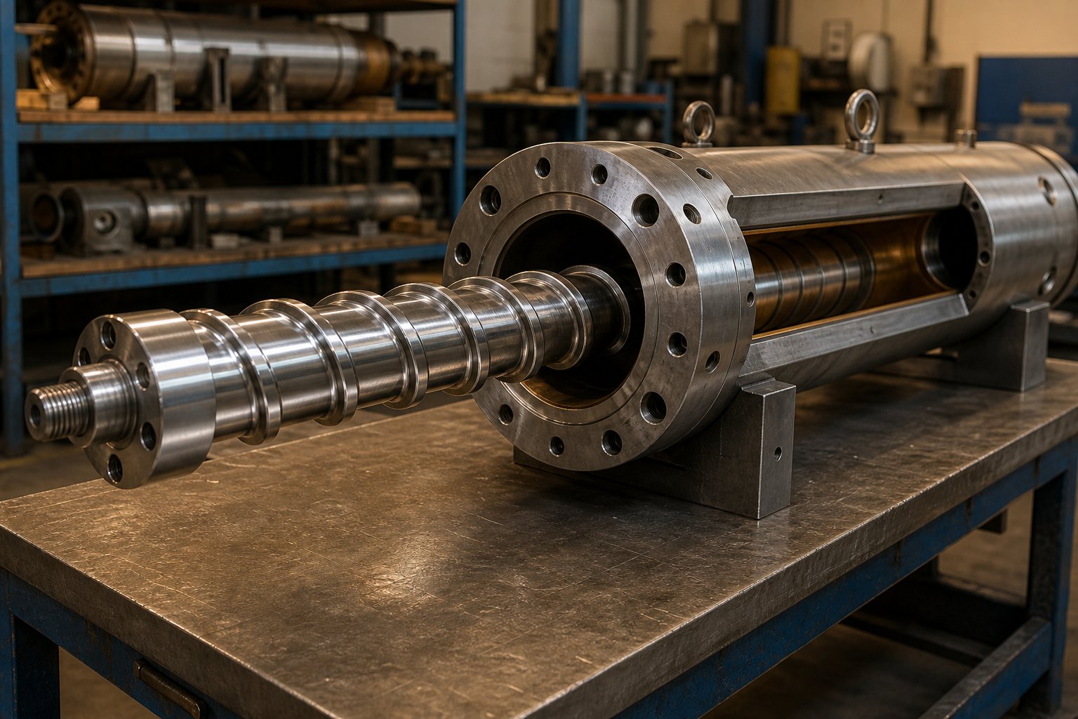
Selecting the Right Screw and Barrel for Profile Extrusion Lines
Every quality system, every inline laser gauge, every precision-machined calibrator in your downstream line relies on one upstream assumption: that the melt arriving at the die is uniform, properly pressurized, and free of unmelted particles or thermal degradation. If that assumption fails, no amount of downstream engineering can rescue the profile. The screw and barrel are where melt quality is born - or lost - and their selection deserves at least as much attention as die design when specifying a plastic profile extrusion line.
Why the Screw and Barrel Are the Heart of Any Extrusion Line
Think of the screw and barrel as the engine block of a profile extruder. The screw conveys raw pellets, compresses them against the heated barrel wall, generates shear energy to complete melting, and meters the homogenized melt forward at consistent pressure. The barrel provides the containment vessel - withstanding internal pressures up to 10,000 psi (approximately 70 MPa) without exceeding 0.15% elastic strain - while transferring heat into or out of the polymer through independently controlled temperature zones.
Three screw design parameters dominate performance:
- L/D ratio (length-to-diameter ratio): General-purpose profile extrusion typically calls for L/D ratios between 24:1 and 30:1. Higher ratios - 32:1 to 40:1 - provide better melting, improved mixing, and more stable pressure development, which benefits materials that are difficult to homogenize or require high output rates. A 60 mm bore with an 1800 mm barrel length, for example, yields a 30:1 ratio suitable for blown film, pipe, and profile applications.
- Compression ratio: This is the ratio of flight depth in the feed zone to flight depth in the metering zone. A 3:1 compression ratio works well for polyolefins like HDPE and LLDPE, while rigid PVC often requires lower compression to avoid shear-sensitive degradation. Mismatching compression ratio to resin creates either unmelted solids (too low) or thermal degradation (too high).
- Flight geometry: Channel width, helix angle, and the presence of mixing elements or barrier flights all influence how effectively the screw separates molten polymer from unmelted solids and delivers a defect-free melt to the die.
Wear resistance is the other critical barrel consideration. Processing polymers with mineral fillers - talc, calcium carbonate, glass fibers, titanium oxide - creates abrasive conditions that erode standard steel surfaces over time. Corrosive compounds like certain PVC formulations and flame-retardant additives attack barrel metallurgy chemically. According to Davis-Standard's engineering guidance, matching screw and barrel material construction is essential to prevent one component from inducing premature wear in the other.
Barrel liner options address these challenges directly:
- Iron-based bimetallic liners: Suitable for general-purpose wear environments processing non-corrosive resins
- Nickel-based liners: Engineered for corrosive compounds including flame-retardant formulations, fluoropolymers, and high-temperature resins
- Tungsten carbide-loaded nickel alloys: The highest wear grade, recommended for highly abrasive filled or reinforced compounds
Screw surface treatments add another layer of protection. Flight tips can be inlaid with stellite or similar hard-facing alloys for abrasion resistance, while root surfaces may receive chrome plating or spray coatings for extreme conditions. Heat treatments such as flame hardening and nitriding further extend service life in demanding profile applications.
Beyond metallurgy, ongoing mechanical checks matter. Straightness of the barrel and screw, proper alignment of the drive system, uniform barrel heating, and adequate barrel support - especially on extended L/D configurations - all prevent premature adhesive wear from metal-to-metal contact. Any profile extrusion company serious about long-term output consistency builds these inspections into its preventive maintenance schedule.
For plants evaluating barrel replacements or specifying new builds, sourcing from suppliers who engineer barrels specifically for the demands of continuous extrusion is essential. NANHAIYA, for instance, manufactures single-screw barrels designed to support diverse applications including profile, pipe, film, sheet, pelletizing, and recycling lines - providing a resource for operations that need reliable barrel solutions matched to their specific resin and throughput requirements.
Building a Reliable Profile Extrusion Line
The screw and barrel are the core, but they operate within a broader equipment ecosystem that must work as a unified system. A plastic profile extrusion line encompasses everything from the drive motor through the final stacking station, and each component must be sized and configured to match the others.
The drive system - typically an AC motor with variable frequency drive (VFD) - provides adjustable rotational speed and stable torque delivery. Modern drives offer energy savings of 20-30% over older DC systems while providing finer speed resolution for sensitive profile geometries. The gearbox reduces motor speed and multiplies torque, while a heavy-duty thrust bearing absorbs the axial loads generated by melt pressure pushing back against the screw.
Temperature controllers manage the barrel's zoned heating and cooling. Each zone operates independently through PID control, with thermocouples providing feedback to maintain setpoints within plus or minus 1 degree Celsius. Effective heat extraction - via air cooling fans or water channels - is just as important as heat input, particularly for shear-sensitive polymers where excessive temperature causes degradation.
Downstream, the calibration table must be long enough to fully size and stabilize the profile before it reaches the haul-off. For PVC window profiles and wide panels, vacuum sizing tables of 4 meters or longer are standard, with vacuum levels reaching -0.096 MPa to lock in dimensional accuracy. Haul-off units need traction force of 10 kN or greater and servo-driven cutting systems that synchronize perfectly with line speed to deliver precise cut lengths without profile distortion.
When evaluating high-performance plastic profile extruders or planning a new line, the following selection criteria should guide every equipment decision:
- Material compatibility: Barrel metallurgy, screw geometry, and temperature range must match the resin family being processed
- Throughput capacity: Output rates for basic PVC profile lines range from 60 to 700 kg/h; high-speed configurations push beyond 500 kg/h for large-format profiles
- Dimensional precision: Calibration table length, vacuum capacity, and haul-off control resolution determine achievable tolerances
- Energy efficiency: Modern AC drives, optimized screw designs, and insulated barrel covers reduce energy cost per kilogram of output
- Vendor support for replacement parts: Screw and barrel wear is inevitable; sourcing from manufacturers who stock or quickly produce replacement components minimizes unplanned downtime
The trend toward modular plastic profile extruders reflects this interconnected reality. Modular systems allow processors to swap screw configurations, change barrel sections, or reconfigure downstream equipment without replacing the entire line - a significant advantage for operations running multiple profile geometries or material families across different production shifts.
Whether you are a profile extrusion co evaluating a complete new line or an existing plant replacing a worn barrel, the principle remains the same: every component must be engineered as part of a system, not selected in isolation. A premium die mounted on an extruder with a mismatched screw geometry or a worn barrel will never deliver the melt quality that precision profiles demand. Invest in the foundation - the screw and barrel - and every downstream stage benefits from the consistency it provides.
Frequently Asked Questions About Profile Extrusion
1. What is the difference between profile extrusion and standard extrusion?
Standard extrusion typically produces simple geometric shapes such as round tubes, flat sheets, or films with uniform thickness. Profile extrusion, on the other hand, creates complex and irregular cross-sectional geometries - including L-channels, multi-chamber hollows, snap-fit ducts, and shapes with varying wall thicknesses, internal fins, and grooves - all formed in a single continuous pass through a custom-engineered die. This ability to handle intricate, non-standard cross-sections is what sets profile extrusion apart and makes it indispensable across industries like construction, automotive, and medical devices.
2. What materials are most commonly used in profile extrusion?
PVC (polyvinyl chloride) dominates the profile extrusion market due to its cost-effectiveness, UV resistance, flame retardance, and processing versatility. Both rigid and flexible PVC formulations are widely extruded into window frames, cable trunking, and gaskets. Beyond PVC, engineering thermoplastics such as ABS, polycarbonate, HDPE, polypropylene, TPE, and nylon serve applications demanding higher impact resistance, elevated service temperatures, or superior chemical resistance. Each resin requires matched screw geometry, barrel temperatures, and die design for optimal results.
3. How much does profile extrusion tooling cost compared to injection molding?
Profile extrusion dies generally cost significantly less than injection molds of comparable complexity. A custom extrusion die for a moderately complex profile may cost a few thousand dollars, whereas an injection mold for a part of similar material volume can easily reach tens of thousands. This lower tooling threshold makes profile extrusion viable even at moderate production volumes where injection molding would be cost-prohibitive on a per-unit basis. However, extrusion is suited only for parts with a constant cross-section, while injection molding handles fully three-dimensional geometries.
4. What is co-extrusion and when should it be used?
Co-extrusion is a technique where two or more different polymers are simultaneously extruded through a shared die to form a unified, multi-material profile in one continuous operation. It is used when a single material cannot deliver all required performance properties - for example, combining a rigid structural core with a soft sealing lip, or applying a UV-resistant cap layer over a cost-effective substrate. Common applications include automotive weatherstripping, multi-layer medical tubing, and PVC window frames with co-extruded color caps. Key challenges include matching melt temperatures, ensuring interlayer adhesion, and managing differential shrinkage between materials.
5. How is quality controlled during the profile extrusion process?
Modern profile extrusion lines use a combination of inline and offline inspection methods. Inline tools such as laser micrometers and vision-based gauging systems monitor dimensions in real time, allowing operators to correct deviations immediately. Ultrasonic gauges measure hollow-profile wall thickness without contact. Offline methods include coordinate measuring machines (CMMs) for verifying complex geometries against CAD models, tensile and impact testing for mechanical validation, and spectrophotometers for color consistency. The calibration unit also plays a critical role by using vacuum or pressure to lock the hot extrudate into its target shape before it can distort.
Written by
Nanhaiya Technical Team
Zhoushan Nanhaiya Plastic Machinery Co., Ltd.
The Nanhaiya technical team supports screw and barrel manufacturing projects through application review, technical communication, custom manufacturing coordination, and production and quality control.
Discuss Your Application
Related Articles
More insights on screw barrel technology and plastics processing.

What Nobody Tells You About Screw Barrel For Plastic Machine Design
Oct 10, 2026
Learn how screw barrel for plastic machine design affects melt quality, throughput, and wear life. Covers geometry, resin matching, troubleshooting, and sourcing.
Read Article
Single Screw Extruder for Sheet: Stop Guessing, Start Specifying
Oct 9, 2026
Learn how to specify a single screw extruder for sheet production. Covers screw geometry, resin-specific processing, troubleshooting, and maintenance best practices.
Read Article
PE Pipe Extruder Machine: What Datasheets Won't Tell You
Oct 9, 2026
Learn how a PE pipe extruder machine works, key specs explained, material grade selection, maintenance tips, and buyer guidance beyond the datasheet.
Read ArticleLooking for something else?
Search by material, symptom or product and jump straight to the relevant page.
These are navigation suggestions based on keyword matching — not a quotation, not a delivery commitment, and not a substitute for engineering review. Final specification is confirmed by our engineers against your drawings and processed material.
Need help with screw barrel selection?
Share your machine model, processed material and application. Our team can help with pricing and technical support.