

What a Powder Coating Twin Screw Extruder Actually Does
Every flaw you see in a finished powder coating — specks, color drift, orange peel, poor gloss — can usually be traced back to one machine. Not the spray gun. Not the curing oven. The extruder. Yet most available information about this critical piece of equipment is either too shallow to be useful or too sales-driven to be trustworthy. This article takes a different approach: a vendor-neutral, technically thorough walkthrough of the powder coating twin screw extruder, written for formulators, production engineers, and anyone who wants to understand what really happens between the premix hopper and the cooling belt.
Defining the Powder Coating Twin Screw Extruder
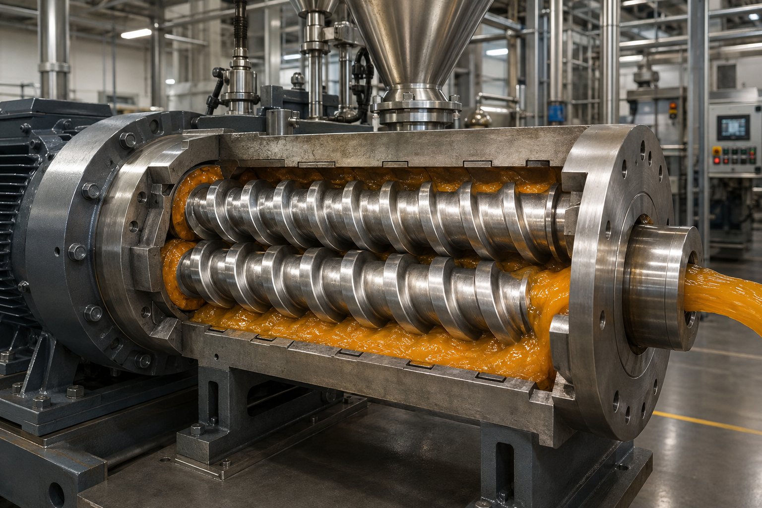
A powder coating twin screw extruder is a compounding machine that converts a dry premix of resins, hardeners, pigments, fillers, and additives into a homogeneous molten compound through precisely controlled shear and heat. Two intermeshing screws rotate inside a heated barrel, melting the resin matrix, breaking apart pigment agglomerates, and distributing every component evenly throughout the melt — all within a tightly managed temperature window. The result is not a finished product shape like a pipe or a profile. Instead, the extrudate is immediately cooled, solidified, and broken into thin flakes that feed downstream grinding mills. Those mills reduce the flakes into the fine, uniform powder that eventually gets electrostatically sprayed onto metal surfaces and cured into a durable coating film.
What does a powder coating extruder do, in the simplest terms? It transforms a loose, heterogeneous dry blend into a dense, perfectly mixed solid compound — and it must accomplish this without accidentally starting the chemical reaction that is supposed to happen later, inside the curing oven.
Why Twin Screws Dominate Powder Coating Production
You might wonder why single screw extruders, which are cheaper and mechanically simpler, are not the standard choice. The answer comes down to the unique demands of thermoset powder coating chemistry. Twin screw extruders for thermoset powder coatings offer several decisive advantages over single screw alternatives:
- Superior distributive mixing: Two intermeshing screws create complex flow patterns that spread pigments, fillers, and additives uniformly through the resin melt — essential for consistent color and surface quality.
- Self-wiping action: The flight of one screw continuously sweeps the surface of the other, preventing material from stagnating in dead zones where it could overheat and begin to crosslink.
- Shorter residence time: Material moves through the barrel quickly and predictably, minimizing thermal exposure — a critical factor when processing heat-sensitive thermoset resins like epoxy, polyester, hybrid, and acrylic systems.
- Tighter thermal control: Precise barrel zone heating and cooling, combined with the efficient heat transfer enabled by twin screw geometry, keeps the melt temperature within the narrow window required to avoid premature curing.
These characteristics explain why twin screw extruders are used for powder coating across virtually every production facility worldwide — from small custom coaters to large-scale manufacturing operations producing thousands of kilograms per hour.
Thermoset powder coating extrusion is a compounding step, not a shaping step. Unlike thermoplastic extrusion, the extrudate has no final geometry. It is immediately cooled on a chilled belt or cooling rolls and broken into flakes for downstream grinding. The extruder's only job is to deliver a perfectly mixed, thermally undamaged compound — and that job is far harder than it sounds.
This distinction matters because it reshapes every design decision inside the machine — from screw element selection to barrel temperature profiles. And those internal details are exactly where coating quality is won or lost, starting with the specific zones inside the barrel itself.
The Complete Powder Coating Production Workflow
Understanding the powder coating twin screw extruder in isolation only gets you halfway. The real insight comes from seeing where it sits within the full manufacturing chain — and recognizing how every step before it sets the stage, while every step after it inherits whatever quality the extruder delivers. Imagine a relay race where the extruder is the anchor leg: it receives the baton from upstream preparation and passes its output forward with no second chances.
From Raw Materials to Finished Powder
The powder coating manufacturing process steps follow a logical sequence, each building on the one before it. Whether you are running a small batch operation or a high-volume production line, the workflow remains fundamentally the same. Here is how powder coatings are manufactured with a twin screw extruder at the heart of the process:
- Weigh-up of raw materials: Formulators measure out resins, crosslinkers (hardeners), pigments, fillers, and additives according to the product recipe. Accuracy here determines whether the final coating meets its target color, gloss, and performance specifications.
- Premixing: The weighed ingredients go into a high-speed mixer — sometimes called a high-intensity blender — that combines everything into a uniform dry premix. This step begins the pigment dispersion process and ensures that no pockets of unmixed raw material reach the extruder. Low-speed tumble or ribbon blenders can also be used, though high-intensity mixing generally produces better consistency and smoother final coatings.
- Twin screw extrusion: The premix is fed into the extruder, where rotating screws melt the resin matrix to a taffy-like consistency and incorporate all components into a homogeneous molten compound. Pigment agglomerates are broken apart under controlled shear. The material spends only about 5 to 10 seconds inside the barrel — just enough time for thorough compounding without triggering the crosslinking reaction that must wait for the curing oven.
- Cooling: The hot extrudate exits the barrel and passes onto chilled rolls or a cooling belt. Chill rolls flatten the melt into a thin sheet, increasing surface area for rapid heat removal. The compound solidifies quickly into a brittle, glass-like state.
- Flaking and crushing: Once cooled, the brittle sheet is broken into small, irregularly shaped flakes — typically a few millimeters across — sized to feed efficiently into the grinding equipment.
- Fine grinding: A pin mill or air classifying mill (ACM) reduces the flakes into the fine powder particles required for electrostatic spraying. Particle size distribution is tightly controlled during this step because it directly affects how the powder fluidizes, pumps, and transfers onto the workpiece. Fluidizing and anti-caking agents are often added at this stage.
- Classifying and sieving: The ground powder passes through a cyclone separator to remove ultra-fine particles, then through a sieve to catch any oversized material. The result is a narrow, controlled particle size distribution.
- Packaging and quality control: The finished powder is packaged into containers, and samples are pulled for testing — color, gloss, reactivity, film smoothness, and other specifications are verified before the batch ships.
This is the powder coating production line workflow in its entirety. Notice that it blends batch operations (weigh-up and premixing happen bowl by bowl) with continuous processing (extrusion through packaging runs without interruption as long as premixed batches keep feeding the extruder).
How Extruder Output Shapes Downstream Quality
Here is the critical point most overviews miss: the extrusion step in powder coating production is not just one link in the chain — it is the link that locks in quality. Once the material exits the extruder, the formula and color are essentially set. If pigment dispersion is incomplete, no amount of grinding will fix it. If the compound is not homogeneous, you will see inconsistencies in every coating film sprayed from that batch.
Think about what the extruder's output directly determines:
- Pigment dispersion quality controls color strength, hiding power, and gloss. Poorly dispersed pigments leave visible specks and reduce tinting efficiency, meaning you need more pigment to achieve the same color — a direct cost penalty.
- Compound homogeneity affects how uniformly flow agents, degassing additives, and hardeners are distributed. Uneven distribution leads to surface defects like craters, orange peel, or inconsistent cure across the finished film.
- Flake thickness and brittleness influence grinding efficiency. Thick, unevenly cooled flakes require more energy to grind and produce broader particle size distributions, which degrade application performance.
- Residual thermal history matters because material that was overheated in the extruder has already consumed part of its crosslinking reactivity. This shifts the gel time and cure window of the finished powder, potentially causing under-cure or over-cure in the oven.
The bottom line is straightforward: poor extrusion cannot be corrected downstream. You cannot re-disperse pigments after the compound has solidified. You cannot restore reactivity lost to thermal damage. You cannot blend away inconsistency once the flakes are ground into powder. The extruder is the quality bottleneck of the entire powder coating manufacturing line, and every decision made inside the barrel — temperature, screw speed, element configuration, feed rate — echoes all the way through to the finished coating on the customer's part.
That reality raises an obvious question: what exactly happens inside each section of that barrel, and how do engineers control it? The answer lies in a zone-by-zone breakdown of the extruder's internal architecture.
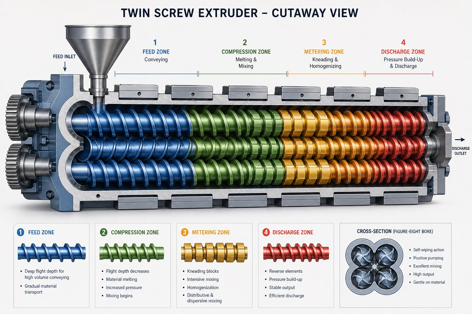
Inside the Barrel — Twin Screw Extruder Barrel Zones Explained
Picture the barrel of a powder coating twin screw extruder as a series of rooms, each with a specific job. Raw material enters one end as a loose, dusty premix and exits the other as a dense, perfectly blended melt — and every zone it passes through plays a distinct role in making that transformation happen. Understanding these zones is not academic trivia. It is the foundation production engineers and formulators rely on when diagnosing quality problems, optimizing throughput, or adapting the machine to a new product family.
Most descriptions of twin screw extrusion lump everything together into vague statements about "melting and mixing." That is not helpful when you are staring at fish-eyes on a coated panel and trying to figure out which barrel section is causing the problem. So let's walk through each zone in detail — the screw elements inside it, the process parameters that matter, and the things that can go wrong.
Feeding and Conveying Zone
Everything starts at the feed throat. The dry premix — a blend of resins, hardeners, pigments, fillers, and additives already combined in a high-speed mixer upstream — drops into the barrel through a feed port and lands on deep-flighted conveying screw elements. These elements look like wide, open spirals. Their job is simple: grab the incoming material and push it forward into the barrel without compressing it prematurely.
The feeder sitting above the feed throat deserves attention because it controls the entire extruder's throughput. You will encounter two main types:
- Volumetric feeders deliver material at a constant volume per unit of time. They are simpler and less expensive, but their accuracy depends on the premix maintaining a consistent bulk density. If the premix is fluffy in one batch and compacted in the next, the actual mass flow rate drifts — and so does your process.
- Gravimetric (loss-in-weight) feeders continuously weigh the hopper and adjust the feed rate to maintain a constant mass flow. They are more expensive but far more accurate, especially when handling premixes with variable bulk density or poor flow characteristics.
For most production-scale powder coating lines, gravimetric feeding is the preferred choice. Premix bulk density can vary depending on how much filler and pigment the formula contains, how aggressively the high-speed mixer compacted the blend, and even ambient humidity. A gravimetric feeder compensates for all of this automatically, keeping the extruder's fill ratio stable and preventing the throughput fluctuations that show up as inconsistent flake thickness or dispersion quality downstream.
One often-overlooked detail: the conveying elements in the powder coating extruder feeding and conveying zone must move material efficiently without generating significant shear or heat. The premix is still a dry solid at this point. Excessive mechanical energy here can cause localized melting at the barrel wall, which creates a sticky film that disrupts material flow and leads to surging. Barrel cooling in this first zone is common practice specifically to prevent that problem.
Melting and Plasticizing Zone
This is where the premix transitions from a loose solid into a viscous melt — and where the thermoset challenge becomes very real. Kneading blocks replace the open conveying elements, and barrel heaters raise the temperature to soften the resin matrix. The combination of conducted heat from the barrel wall and mechanical energy from the kneading action transforms the dry blend into a taffy-like mass.
Sounds straightforward, but here is the catch. The melting and mixing zones in a powder coating extruder must operate within a narrow thermal window. The barrel temperature has to be high enough to fully melt the resin and allow the pigments and fillers to wet out and incorporate — yet it must stay well below the crosslinking onset temperature of the thermoset system. Cross that threshold, and you start generating gels that ruin the batch.
How narrow is that window? It depends on the resin chemistry:
- Epoxy systems typically offer a relatively wider processing range, with crosslinking onset temperatures that allow moderate barrel setpoints.
- Polyester-TGIC and polyester-HAA systems can be more thermally sensitive, requiring tighter temperature control, especially in the melting zone where the resin first becomes fluid and reactive groups gain mobility.
- Hybrid (epoxy-polyester) systems fall somewhere in between, but their dual-resin nature means both components must melt and blend before either begins to react.
- Acrylic systems often have lower crosslinking onset temperatures and demand the most conservative thermal profiles.
Production engineers monitor actual melt temperature — not just barrel setpoint temperature — because viscous shear heating inside the kneading blocks can push the melt 10 to 20 degrees Celsius above the barrel wall temperature. That difference is where premature crosslinking hides.
Dispersive and Distributive Mixing Zones
Once the resin is molten, the real mixing work begins. This is the heart of the compounding process, and understanding the distinction between dispersive and distributive mixing is essential for anyone troubleshooting color consistency or surface quality issues.
Dispersive mixing is about breaking things apart. Pigment particles arrive in the premix as agglomerates — clusters of primary particles held together by surface forces. Dispersive mixing subjects these agglomerates to high shear stress, fracturing them down to their primary particle size. Narrow kneading blocks with aggressive stagger angles — often 60 or 90 degrees — generate the intense shear fields needed for this task. Without adequate dispersive mixing, you get visible specks, reduced color strength, and inconsistent gloss across the cured film.
Distributive mixing is about spreading things evenly. Even if every pigment agglomerate has been broken apart, the individual particles, fillers, flow agents, and other additives still need to be uniformly distributed throughout the entire melt volume. Wide kneading blocks, toothed mixing elements, and gear-type mixing elements create the splitting and recombining flow patterns that achieve this homogeneity. Poor distributive mixing shows up as color streaks, uneven surface texture, and batch-to-batch variation in coating performance.
In practice, the screw elements for each extruder barrel zone in these mixing sections are carefully sequenced. A typical approach starts with narrower, more aggressive kneading blocks for dispersive work, then transitions into wider or gear-type mixing elements for distribution. The exact arrangement depends on the formulation — a point we will revisit in detail when we discuss screw configuration philosophy.
Discharge Zone
After the mixing zones have done their work, the melt reaches the discharge section at the barrel's downstream end. Here, deep-flighted conveying elements build pressure to push the homogeneous compound out of the barrel through a die plate or an open discharge port.
Unlike thermoplastic extrusion, there is no need for a precisely shaped profile, tube, or film die. The only goal is to deliver the melt as a thin sheet or set of strands onto a cooling belt or between chilled rolls for rapid solidification. A thinner output means faster cooling, which minimizes additional thermal exposure — an important consideration for thermoset compounds that have already spent their limited heat budget inside the barrel.
Some extruder setups include a screen pack or breaker plate at the discharge to catch any undispersed agglomerates or foreign contamination before the melt reaches the cooling equipment. This acts as a final quality gate, though it also creates back pressure that can raise melt temperature slightly — another trade-off engineers must manage.
Zone-by-Zone Reference Summary
The table below consolidates each barrel zone's function, the screw elements typically installed, and the critical process parameters to watch. Bookmark it — you will find yourself coming back to it when troubleshooting or setting up a new product run.
| Barrel Zone | Primary Function | Typical Screw Elements | Key Process Parameters to Monitor |
|---|---|---|---|
| Feeding and Conveying | Intake of dry premix; forward transport without premature melting | Deep-flighted conveying elements (large pitch) | Feed rate stability, barrel wall temperature (kept cool), hopper flow consistency |
| Melting and Plasticizing | Softening and melting the resin matrix to form a continuous melt phase | Kneading blocks (medium stagger angles), transitional conveying elements | Barrel zone temperatures, actual melt temperature, motor torque |
| Dispersive Mixing | Breaking down pigment agglomerates under high shear | Narrow kneading blocks (60° or 90° stagger), reverse elements for back pressure | Melt temperature rise, screw speed, shear rate indicators |
| Distributive Mixing | Uniform distribution of all components throughout the melt | Wide kneading blocks (30° or 45° stagger), toothed or gear mixing elements | Compound homogeneity (checked via color and gloss on test panels), residence time |
| Discharge | Pressure build-up and expulsion of the melt for cooling | Deep-flighted conveying elements (standard pitch), optional screen pack | Die pressure, melt temperature at exit, visual quality of extrudate sheet |
Each of these zones interacts with its neighbors. A change in feed rate alters the fill level in the melting zone. A more aggressive kneading block arrangement raises melt temperature, which affects how much cooling the discharge zone needs to compensate. The barrel is a system, not a collection of independent compartments — and optimizing it requires understanding how those interactions ripple through the entire screw profile.
That systemic thinking becomes even more important when you consider that the screws themselves come in fundamentally different geometric configurations — each with distinct strengths and trade-offs for thermoset powder coating production.
Twin Screw Design Comparison for Powder Coatings
Not all twin screw extruders are built the same way. The direction the screws rotate, and whether or not they physically intermesh, fundamentally changes how material flows through the barrel, how much shear the melt experiences, and how precisely you can control thermal exposure. For thermoset powder coatings — where every excess degree of heat carries the risk of premature crosslinking — these geometric differences are not minor engineering footnotes. They determine what you can process, how fast you can run, and how consistent your final coating will be.
So which configuration is the best twin screw configuration for powder coating? Let's break down the three main designs and see where each one fits.
Co-Rotating Intermeshing Twin Screws
This is the dominant configuration in modern powder coating production, and for good reason. In a co-rotating intermeshing design, both screws turn in the same direction and their flights mesh tightly together. That geometry creates a self-wiping action — the flight crest of one screw continuously sweeps material off the root of the other, preventing stagnation and eliminating dead zones where resin could overheat and gel.
The co-rotating twin screw advantages for thermoset coatings go beyond self-cleaning. The intermeshing geometry generates figure-eight flow patterns that deliver excellent distributive and dispersive mixing in a remarkably short barrel length. Material moves through quickly and predictably, giving engineers tight control over residence time — a critical lever when your processing window is only a few degrees wide.
Another practical benefit: modularity. Co-rotating machines use segmented screw shafts onto which individual conveying elements, kneading blocks, and mixing elements can be arranged in virtually any sequence. When you switch from a heavily filled titanium dioxide white to a transparent clear coat, you can reconfigure the screw profile to match the new formulation's mixing demands without replacing the entire screw set. That flexibility makes co-rotating intermeshing extruders the workhorse of multi-product powder coating facilities.
Counter-Rotating Intermeshing Twin Screws
When the screws turn in opposite directions and still intermesh, the geometry creates enclosed C-shaped chambers between the flights. Material is trapped in these pockets and conveyed forward in a very positive, piston-like manner. This closed-chamber transport mechanism gives counter-rotating intermeshing machines an edge in one specific area: extremely predictable material conveyance with minimal back-mixing.
For certain heat-sensitive formulations — imagine a highly reactive acrylic system where even modest back-mixing would extend residence time past the safety margin — this positive-displacement behavior can be advantageous. The material spends a well-defined, uniform amount of time inside the barrel, reducing the risk of localized overheating.
The trade-offs, however, are significant. Counter-rotating intermeshing screws generate higher inter-screw forces, which accelerates wear on both the screw elements and barrel liners — a particular concern in powder coating applications already dealing with abrasive mineral fillers. Maximum throughput capacity is generally lower than co-rotating designs of the same screw diameter. And because the closed-chamber geometry inherently limits the complex flow splitting and recombining that drives distributive mixing, achieving the same level of pigment homogeneity often requires a longer barrel or additional mixing sections.
Counter-Rotating Non-Intermeshing Twin Screws
In this configuration, the screws rotate in opposite directions but do not mesh — a gap exists between them. Material transfers between the screws through this open space rather than being positively conveyed in closed chambers. The result is a gentler, lower-shear environment with significant back-mixing.
Why does this see limited use in powder coating applications? The very features that make it gentle — open gaps, extensive back-mixing, longer residence times — work against the thermoset processing imperative of getting material through the barrel quickly and uniformly. The lack of intermeshing also eliminates the self-wiping benefit, increasing the likelihood of material stagnation and localized gel formation. You will occasionally encounter this design in specialty applications or older installations, but it is not a realistic choice for modern thermoset powder coating compounding.
Side-by-Side Configuration Comparison
The table below puts all three configurations next to each other across the parameters that matter most in an intermeshing twin screw extruder powder coating comparison. Use it as a quick reference when evaluating equipment options or understanding why your facility runs the configuration it does.
| Parameter | Co-Rotating Intermeshing | Counter-Rotating Intermeshing | Counter-Rotating Non-Intermeshing |
|---|---|---|---|
| Mixing Efficiency | Excellent — strong dispersive and distributive mixing | Good — strong conveying, moderate mixing | Moderate — relies on back-mixing, limited dispersive shear |
| Residence Time Control | Very good — narrow, predictable distribution | Excellent — closed chambers give uniform transport | Poor — broad residence time distribution due to back-mixing |
| Throughput Capacity | High — scales well with screw diameter | Moderate — limited by inter-screw pressure constraints | Moderate to low |
| Self-Wiping Capability | Yes — continuous flight-to-root wiping | Partial — wiping occurs but with higher contact stress | No — open gap between screws |
| Thermal Control Precision | Very good — short residence time plus efficient barrel cooling | Good — uniform transport helps, but higher friction adds heat | Fair — long residence time complicates thermal management |
| Screw/Barrel Wear Rate | Moderate — manageable with proper metallurgy | Higher — inter-screw forces accelerate wear | Lower mechanical wear, but stagnation risk offsets the benefit |
| Modularity | High — fully segmented screw elements on splined shafts | Moderate — some designs offer modular elements | Low — typically fixed screw geometry |
| Powder Coating Suitability | Industry standard — preferred for nearly all thermoset powder coating formulations | Niche — suitable for specific heat-sensitive or low-volume applications | Rarely used — not recommended for thermoset powder coatings |
The comparison makes the industry's preference clear. Co-rotating intermeshing machines deliver the combination of mixing quality, throughput, thermal safety, and flexibility that thermoset powder coating production demands. Counter-rotating intermeshing designs occupy a valid niche for specialized formulations, but their limitations in mixing efficiency and wear resistance keep them from displacing the co-rotating standard. And counter-rotating non-intermeshing machines, while useful in other polymer processing contexts, simply do not align with the short-residence-time, high-dispersion, thermally constrained reality of powder coating compounding.
Choosing the right screw configuration is only half the equation, though. Even within a co-rotating intermeshing machine, the way engineers handle the fundamental tension between shear energy and heat generation — the defining challenge of thermoset extrusion — separates a good process from one that produces gel-filled rejects.
Why Thermoset Extrusion Demands Different Rules
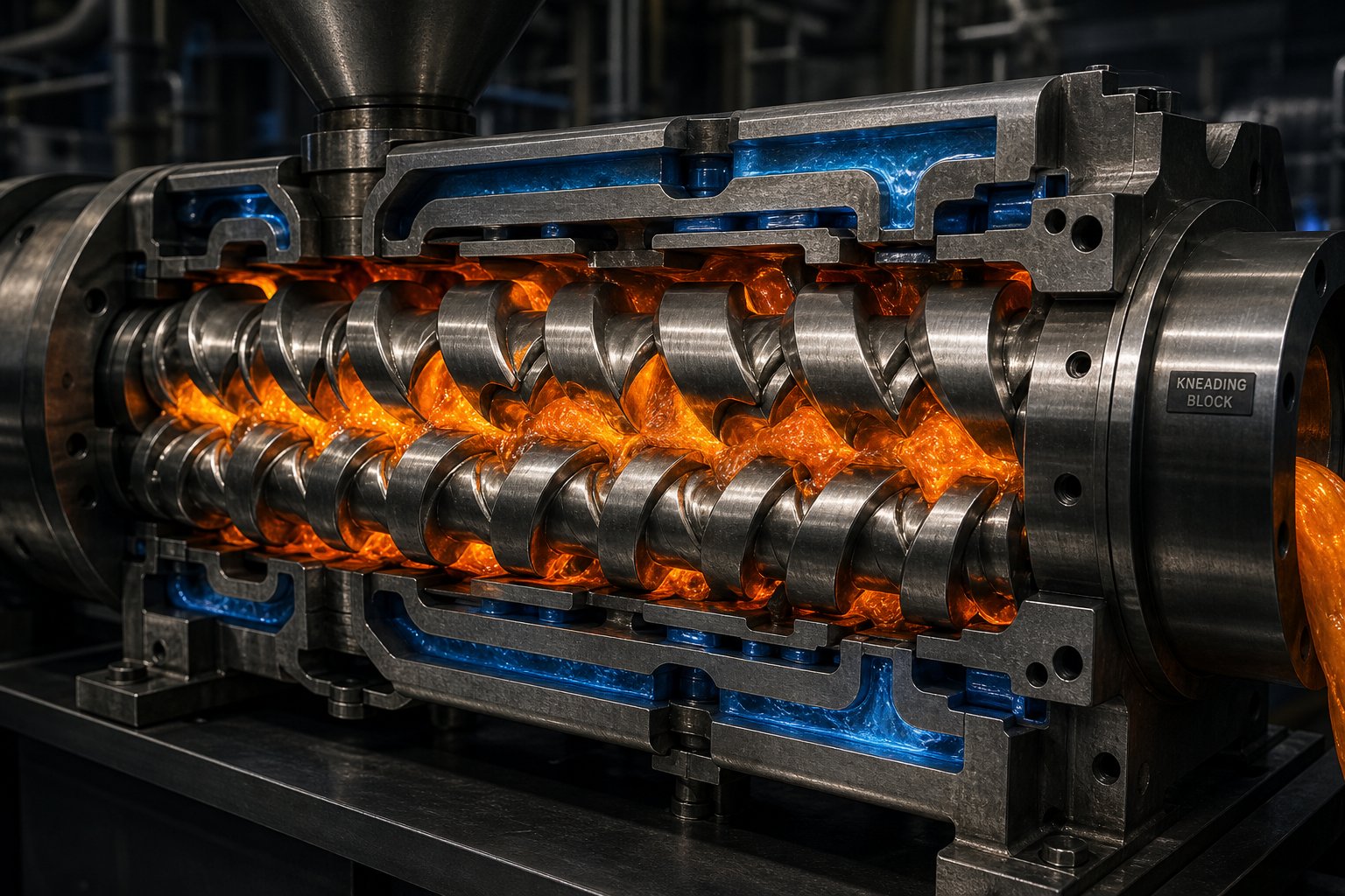
If you have spent any time running thermoplastic compounding lines, stepping into thermoset powder coating extrusion feels like switching from highway driving to navigating a mountain road with no guardrails. The basic machinery looks similar — same twin screw barrel, same modular elements, same control panels. But the margin for error shrinks dramatically. In thermoplastic processing, overheating a melt usually means degraded properties or discoloration — problems you can often detect, adjust for, and sometimes even salvage. In thermoset powder coating extrusion, overheating triggers an irreversible chemical reaction that turns part of your melt into permanent, insoluble debris. There is no going back.
This single difference — the ever-present threat of premature crosslinking — is the defining challenge that separates powder coating extrusion from virtually every other compounding application. It dictates barrel temperatures, screw speeds, element configurations, and even how aggressively you can pursue pigment dispersion. Understanding it is not optional for anyone running or specifying these machines.
The Premature Crosslinking Problem
Here is what actually happens inside the barrel when things go wrong. Thermoset powder coating resins — epoxies, polyesters, hybrids, acrylics — contain reactive functional groups that are designed to crosslink. That crosslinking reaction is supposed to occur later, inside the curing oven at 160 to 200 degrees Celsius, where it transforms the sprayed powder film into a hard, chemically resistant coating. The resin and hardener are intentionally formulated so that this reaction stays dormant at lower temperatures, giving the manufacturer a safe processing window to melt, mix, and compound the material without triggering the cure.
But that dormancy has limits. Expose the melt to excessive temperature or let it sit in the barrel too long, and the reactive groups start finding each other. Molecular chains begin linking together. Once enough crosslinks form, localized regions of the melt transform from a flowable liquid into an insoluble, rubbery solid — a process called gelation. These gelled regions become tiny specks embedded in the surrounding melt, and no amount of shear or remelting will break them apart. They are chemically locked.
When the compound is cooled, ground into powder, sprayed onto a part, and cured in the oven, those gels show up as fish-eyes — small raised bumps or craters in the finished coating surface. They scatter light differently than the surrounding film, creating visible defects that are immediately obvious on high-gloss or smooth-finish coatings. A single production run contaminated with gels can mean scrapped product, rework, and customer complaints. In severe cases, the entire batch is unusable.
What makes this particularly tricky is that different resin systems have different crosslinking onset temperatures, so premature crosslinking in powder coating extrusion is not a one-size-fits-all risk. Consider the range:
- Epoxy systems generally offer the most forgiving processing window. Their crosslinking onset temperatures tend to sit comfortably above the melt temperatures needed for good dispersion, giving operators a reasonable buffer zone. This is one reason epoxy-based formulations are often recommended for newcomers to powder coating production.
- Hybrid (epoxy-polyester) systems contain two different resin types that must both melt and intermix before any crosslinking begins. The processing window narrows compared to straight epoxies, and the interaction between the two resin chemistries adds complexity to thermal management.
- Polyester-TGIC systems require careful attention. The TGIC crosslinker can begin reacting with the polyester's carboxyl groups at temperatures that are not far above the melting point, particularly if residence time extends beyond the design target.
- Polyester-HAA systems use hydroxyalkylamide hardeners that can be quite thermally sensitive. These formulations often demand the most conservative barrel temperature profiles in the polyester family.
- Acrylic systems sit at the most challenging end of the spectrum. Many acrylic powder coating resins have low crosslinking onset temperatures, meaning the gap between "fully melted and mixable" and "starting to gel" can be uncomfortably small — sometimes only 15 to 25 degrees Celsius of usable range.
This is not a theoretical concern. Production engineers switching between product families routinely adjust barrel zone temperatures, screw speeds, and throughput rates to stay inside each system's safe processing window. Running an acrylic formulation on the same temperature settings used for an epoxy is a reliable way to generate a barrel full of gelled material.
Balancing Shear, Dispersion, and Thermal Control
Here is the fundamental tension that makes thermoset powder coating extrusion so demanding compared to thermoplastic compounding. Excellent pigment dispersion requires mechanical energy. Breaking apart pigment agglomerates — clusters of primary particles bonded by surface forces — demands high shear stress, which comes from aggressive kneading block configurations and elevated screw speeds. More shear means better color development, higher gloss, and stronger hiding power in the cured film.
But shear generates heat. Every time the screw elements force the viscous melt through a narrow gap or a kneading block nip, mechanical energy converts into thermal energy through viscous dissipation. The melt temperature rises — not because the barrel heaters are set too high, but because the mixing action itself is pumping heat into the material. In thermoplastic compounding, this is manageable. You might need to add barrel cooling, but the polymer itself can tolerate a wide temperature range without catastrophic consequences. In thermoset extrusion, every degree of shear-induced heating eats into your already narrow safety margin, pushing the melt closer to the crosslinking threshold.
This is the trade-off that experienced engineers wrestle with on every formulation: push harder for better dispersion and risk gelation, or play it safe thermally and accept that some pigment agglomerates may survive the process. The best operations find a balance through several interrelated strategies:
- Optimized screw speed: Running the screws faster increases shear rate and improves dispersion — but it also increases viscous heating and reduces residence time. There is a sweet spot where dispersion quality peaks before thermal damage begins. Finding it often requires systematic trials at different speed-throughput ratios.
- Aggressive barrel cooling: Applying maximum cooling capacity to the mixing zones pulls heat out of the barrel wall, creating a thermal gradient that counteracts shear heating. Some operations run mixing zone barrel temperatures 20 to 30 degrees below the target melt temperature, relying on the screw's mechanical energy to bring the melt to the right consistency while the barrel actively removes excess heat.
- Shortened high-shear mixing zones: Rather than running long kneading block sections that accumulate shear heat over many barrel diameters, effective powder coating screw profiles concentrate dispersive mixing into short, intense bursts separated by conveying elements that allow the melt to relax and cool against the barrel wall.
- Careful kneading block stagger angles: Narrow-disc kneading blocks at 90-degree stagger generate maximum shear but also maximum heat. Blocks at 60 degrees offer a compromise — strong dispersive action with somewhat less viscous dissipation. Blocks at 30 or 45 degrees focus more on distributive mixing with less heat generation. Engineers select and sequence these elements to deliver the required dispersion with the minimum possible thermal penalty.
In practice, shear heat control in thermoset twin screw extrusion often comes down to monitoring the actual melt temperature at the die exit — not the barrel setpoint temperatures displayed on the control panel. As industry analysis of heating rate effects confirms, the melt temperature can run significantly above the barrel wall temperature due to viscous dissipation, and this gap widens as screw speed increases or throughput drops. An engineer who watches only barrel temperatures while ignoring the actual melt reading is flying blind in exactly the zone where thermoset resins are most vulnerable.
The processing window for thermoset powder coatings is significantly narrower than for most thermoplastic compounding applications. Where a thermoplastic melt might tolerate a 60 to 80 degree Celsius range between its processing temperature and its degradation point, thermoset powder coating resins often operate within 20 to 40 degrees of their crosslinking onset — and that margin shrinks further when viscous shear heating is factored in.
This constrained reality is exactly why how to prevent gelation in a powder coating extruder is not about any single adjustment. It is a systems-level challenge involving screw element selection, barrel thermal management, feed rate-to-screw-speed ratios, and formulation awareness all working together. Miss one variable, and the others cannot fully compensate.
That systems-level perspective extends naturally into the screw elements themselves — the individual building blocks that engineers arrange and rearrange to create a screw profile tuned to each formulation's unique combination of mixing needs and thermal sensitivity.
Screw Element Configuration for Powder Coating Applications
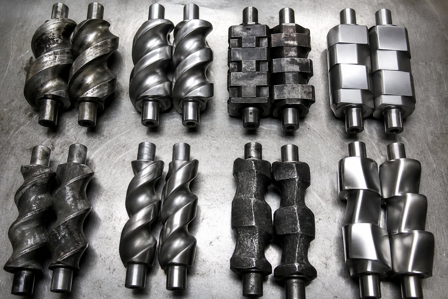
Imagine having a toolbox where every wrench, socket, and driver can be rearranged on a single shaft to build a completely different tool for each job. That is essentially how a modular twin screw works. The screw shaft itself is just a splined rod — the real engineering lives in the individual elements stacked onto it. Conveying elements, kneading blocks of varying widths and angles, specialized mixing elements, and reverse-flight segments each contribute a distinct mechanical action to the melt. Rearrange them, and you fundamentally change how the extruder handles your formulation.
For powder coating production, getting this arrangement right is not a luxury — it is the difference between a batch that meets color, gloss, and smoothness specs on the first pass and one that generates customer complaints. Yet twin screw element configuration for powder coatings rarely gets the detailed treatment it deserves. Most discussions stop at "use kneading blocks for mixing" without explaining how element selection, sequencing, and spacing interact with the thermoset processing constraints covered in the previous section.
Building a Screw Profile for Powder Coatings
Every co-rotating intermeshing twin screw extruder used in powder coating production relies on a modular screw design for thermoset compounding. Engineers slide individual elements onto splined shafts, lock them in sequence with a threaded tip, and create a complete screw profile tailored to the formulation at hand. Swap a few elements, and the same machine behaves differently — more shear here, gentler conveying there, longer residence in one zone, shorter in another.
The general design philosophy for powder coatings follows a clear pattern that reflects the narrow thermal processing window discussed earlier: moderate shear intensity, short high-shear zones, extended conveying sections, and efficient melt discharge. Contrast this with a typical thermoplastic compounding profile, which might use long sequences of aggressive kneading blocks to maximize filler incorporation or polymer blending. In thermoset powder coating extrusion, every additional kneading block adds shear heat that eats into your crosslinking safety margin. So the guiding principle is always: use only as much shear as the formulation demands for adequate dispersion — and not a single element more.
In practice, a typical powder coating screw profile breaks down into recognizable sections. The upstream portion consists almost entirely of large-pitch conveying elements that move the dry premix forward without generating heat. A short, carefully designed kneading block sequence handles melting and initial plasticization. A second kneading or mixing section — often separated from the first by a conveying "relaxation" zone — provides the dispersive and distributive mixing that breaks apart pigment agglomerates and homogenizes the melt. Finally, deep-flighted conveying elements in the discharge zone build pressure to push the compound out of the barrel.
The kneading block arrangement in a powder coating extruder is where most of the fine-tuning happens. As real-world screw layout guidance confirms, kneading block stagger angles are the primary lever for adjusting shear intensity. Small stagger angles — 30 or 45 degrees — produce gentle folding and recombining flow patterns suited to distributive mixing. Larger angles — 60 or 90 degrees — create intense shearing action that fractures pigment agglomerates but also generates substantially more viscous heat. For powder coatings, you will typically see alternating sequences of moderate-angle blocks rather than long runs of aggressive 90-degree elements. This delivers the required dispersion in controlled bursts, with conveying elements between each burst allowing the melt to cool against the barrel wall before encountering the next high-shear zone.
Reverse-flight elements deserve special mention. Placed strategically within the screw profile, these backward-facing conveying segments create a local dam that forces material to build up pressure before passing through. They increase fill level and residence time in the zone immediately upstream, which can improve mixing completeness in a preceding kneading block section. In powder coating applications, reverse elements are used sparingly — too much back pressure means too much residence time, which circles right back to the gelation risk. But a single reverse element placed after a dispersive mixing section can meaningfully improve pigment wetting without extending overall barrel residence time to dangerous levels.
How Raw Material Properties Drive Configuration Choices
Here is where screw configuration stops being a textbook exercise and becomes a practical, formulation-specific decision. Different powder coating products place very different demands on the mixing sections, and production engineers routinely modify element arrangements when switching between product families. A single "universal" screw profile does not exist for a facility running whites, metallics, clears, and textured finishes.
Consider a few common scenarios. A standard white formula loaded with 20 to 30 percent titanium dioxide by weight presents a distributive mixing challenge. TiO2 particles are relatively easy to break apart — they do not form stubborn agglomerates the way some organic pigments do — but they need to be spread evenly through a very large volume of filler material. This calls for extended distributive mixing zones with wide kneading blocks at moderate stagger angles, toothed mixing elements, or gear-type dispersing sections that split and recombine the melt stream repeatedly without generating excessive shear heat.
Switch to a formulation containing a difficult-to-disperse organic pigment — certain phthalocyanine blues or carbon blacks, for example — and the priorities flip. These pigments form tightly bonded agglomerates that resist breakup. The screw profile needs stronger dispersive zones: narrower kneading blocks at 60 or 90 degrees that subject the melt to the high shear stress required to fracture those clusters down to primary particle size. Color strength and gloss depend directly on how thoroughly these agglomerates are destroyed. But the increased shear also means increased viscous heating, so the engineer must compensate with aggressive barrel cooling and possibly a shorter overall mixing section length.
Resin reactivity adds another layer. Low-reactivity epoxy or hybrid systems give the engineer more room to experiment with aggressive kneading configurations. The crosslinking onset temperature sits comfortably above the melt processing range, so the thermal margin tolerates a bit more shear heating. Highly reactive systems — fast-cure polyester-HAA formulations or thermally sensitive acrylics — demand the opposite approach. Gentler profiles with minimal shear heating, shorter residence times, and fewer total kneading elements become essential to prevent gelation. In extreme cases, engineers may accept slightly lower dispersion quality rather than risk pushing melt temperatures into the danger zone.
Highly filled formulations containing large amounts of barium sulfate, calcium carbonate, or other mineral extenders present yet another challenge. These fillers increase melt viscosity significantly, which amplifies shear heating at any given screw speed. The screw profile may need wider conveying gaps to accommodate the higher torque demand, and kneading block sections may need to be shortened or operated at lower stagger angles to keep the viscous dissipation manageable.
The key takeaway for anyone looking to optimize screw profile for powder coating extrusion is this: screw configuration is not set-and-forget. It is a living, formulation-driven decision that production teams revisit whenever the product mix changes, raw material suppliers shift, or quality targets tighten. Facilities that treat their screw profile as fixed hardware rather than adjustable process tooling leave performance on the table — and often struggle with defects that a simple element rearrangement could resolve.
Screw Element Types and Their Roles in Powder Coating Extrusion
For a quick reference, here are the main screw element types you will encounter on a powder coating twin screw extruder and what each one contributes to the compounding process:
- Large-pitch conveying elements: Used in the feed zone and between mixing sections. They move material forward rapidly with minimal shear or heat generation. Extended conveying sections give the melt time to cool against the barrel wall between high-shear zones — a critical function in thermoset processing.
- Standard-pitch conveying elements: Provide forward transport with moderate compression. Commonly used in transition zones and the discharge section to build pressure for melt expulsion.
- Narrow kneading blocks (thin disc, 60° or 90° stagger): The primary dispersive mixing elements. They generate intense localized shear to fracture pigment agglomerates and break down filler clusters. Used in short sequences to limit cumulative shear heating.
- Medium kneading blocks (45° or 60° stagger): Offer a balance between dispersive and distributive mixing. Commonly the backbone of the melting and primary mixing zones in powder coating profiles.
- Wide kneading blocks (30° or 45° stagger): Emphasize distributive mixing — spreading components evenly through the melt rather than breaking them apart. Ideal for homogenizing highly filled or multi-pigment formulations without excessive heat input.
- Toothed or gear mixing elements: Create splitting and recombining flow patterns that enhance distributive mixing with relatively low shear stress. Useful for final homogenization stages where thermal sensitivity limits the use of kneading blocks.
- Reverse-flight (left-handed) conveying elements: Generate localized back pressure, increasing fill level and residence time in the upstream zone. Used sparingly in powder coating profiles to intensify mixing in a targeted area without extending overall residence time.
- Neutral (90° stagger) kneading blocks: Also called "non-forwarding" kneading blocks. They create a pressure dam similar to reverse elements but with high shear intensity. Rarely used in thermoset powder coating applications because of the extreme heat generation, but occasionally employed for the most stubborn dispersion challenges.
Every element on that list is a tool with a specific purpose. The art — and it genuinely is part art, part engineering — lies in sequencing them into a profile that delivers complete dispersion and homogeneity while respecting the thermal boundaries of the resin system being processed.
Even the best-designed screw profile, however, cannot prevent every problem. Wear, feed inconsistencies, and process drift introduce defects over time that require a different kind of expertise — not design thinking, but diagnostic troubleshooting on the production floor.
Troubleshooting Common Powder Coating Extrusion Defects
A well-designed screw profile and a properly set temperature map can keep a powder coating extruder running smoothly for weeks. Then one morning, the lab pulls a test panel and finds specks, color drift, or surface craters that were not there yesterday. What changed? Diagnosing extrusion defects in thermoset powder coating production requires a systematic approach — not random knob-turning — because the root cause is rarely what it first appears to be. This powder coating extrusion troubleshooting guide covers the three defect families that account for the vast majority of production-floor headaches: pigment dispersion failures, gels and thermal degradation, and throughput instability driven by mechanical wear.
Pigment Dispersion Failures and Color Inconsistency
When coated panels show weak color development, visible specks, reduced gloss, or batch-to-batch color drift, the problem almost always traces back to incomplete pigment dispersion inside the extruder. But "poor dispersion" is a symptom, not a diagnosis. You need to identify which specific mechanism is falling short.
The most common causes of poor pigment dispersion in a twin screw extruder include:
- Insufficient shear energy: The kneading block configuration may not generate enough stress to fracture pigment agglomerates — particularly tightly bonded organic pigments like phthalocyanine blues or carbon blacks. If the screw profile was designed for an easier-to-disperse formulation and was never updated, dispersion quality suffers immediately when you switch to a more demanding product.
- Feed rate too high relative to screw speed: Overfeeding floods the mixing zones, reducing the specific mechanical energy delivered per kilogram of material. Each particle gets less shear work, and agglomerates survive the process intact. Lowering the feed rate or increasing screw speed — while monitoring melt temperature — often resolves this quickly.
- Worn screw elements and barrel liners: This is the insidious one. Wear does not happen overnight, so the degradation creeps in gradually. As kneading block flight crests round off and the intermeshing clearance between the two screws widens, the peak shear stress the elements can deliver drops. Material passes through the mixing zones without experiencing enough force to break apart agglomerates. Worn barrel liners compound the problem — the gap between the screw flight tip and the barrel wall increases, allowing material to bypass the high-shear zone entirely. If color consistency has been drifting slowly worse over months despite no formulation changes, worn hardware is the first place to look.
- Incorrect kneading block arrangement: A screw profile heavy on distributive mixing elements but light on dispersive ones will spread components evenly without breaking agglomerates apart. The result is a uniformly distributed population of undispersed pigment clusters — consistent color, but weak color and low gloss.
Gels, Fish-Eyes, and Thermal Degradation
Few defects are more alarming than finding fish-eyes and gels in powder coating extrusion output. Those small, hard specks embedded in an otherwise smooth coating film represent permanently crosslinked material — resin that cured prematurely inside the extruder and can never be remelted, redispersed, or removed by any downstream process. When a customer's quality inspector circles a raised bump on a gloss panel, the damage was already done minutes earlier inside the barrel.
Gels form through premature crosslinking triggered by one or more of these conditions:
- Excessive melt temperature: The most direct cause. When barrel zone temperatures are set too high, or when viscous shear heating pushes the actual melt temperature past the crosslinking onset point, reactive functional groups in the thermoset resin begin linking together. Remember — the melt temperature at the die exit can run 10 to 20 degrees Celsius above barrel setpoints due to viscous dissipation, so relying only on the control panel display is dangerous.
- Dead spots in the screw profile: Any location where material stagnates — a poorly designed transition between elements, a gap in the screw assembly, or a section where wear has created an unswept pocket — allows resin to sit at elevated temperature far longer than the intended residence time. That trapped material slowly gels, and when the main melt stream eventually dislodges a piece of it, the result is a sudden outbreak of specks across the production run. As practical troubleshooting research confirms, dead-zone deposits can contaminate production for extended periods before they are identified and cleaned.
- Excessive residence time: Running the extruder at very low throughput while maintaining normal screw speed extends the time material spends inside the barrel. Even if temperatures are nominally within range, the cumulative thermal exposure pushes the resin past its safe limit. This commonly happens during startups, shutdowns, or grade transitions when the extruder is not running at design capacity.
Thermal degradation also affects components beyond the resin itself. Flow agents, degassing additives, and other thermosensitive ingredients can degrade at high melt temperatures, losing their effectiveness. When flow agents break down, the cured coating develops orange peel — a bumpy, textured surface that should have been smooth. When degassing additives fail, trapped volatiles create pinholes and craters in the finished film. These defects often appear alongside gels, which makes sense — the same overheating event that triggers premature crosslinking simultaneously damages the heat-sensitive additives in the formulation.
Surging, Throughput Instability, and Mechanical Wear
If the extrudate sheet emerging from the die pulses in thickness — alternately thick and thin in a rhythmic pattern — you are dealing with surging. Powder coating extruder surging and throughput problems trace back to inconsistent material delivery or compromised conveying capability inside the barrel.
Common causes include:
- Inconsistent feeding: Volumetric feeders that cannot compensate for batch-to-batch variations in premix bulk density send fluctuating amounts of material into the barrel. Gravimetric feeders are more stable, but even they struggle if the premix has poor flow characteristics — clumping, bridging in the hopper, or rat-holing that causes sudden flow surges followed by dry spells.
- Hopper bridging: Premixes containing high percentages of fine fillers or tacky additives can arch across the hopper throat, blocking flow until the bridge collapses and dumps a slug of material into the feed zone all at once. Installing hopper agitators, vibrators, or adjusting the hopper geometry often resolves this.
- Worn conveying elements: As the flight tips on conveying elements wear down, their ability to grip and push material forward weakens. The screws start slipping relative to the material bed, and output fluctuates. This is a gradual process that often goes unnoticed until surging becomes severe enough to affect downstream flake quality and grinding consistency.
Barrel and screw wear in powder coating production deserves special emphasis because it progresses faster than many operators expect. Powder coating formulations are inherently abrasive. Mineral fillers like calcium carbonate, barium sulfate, wollastonite, and silica — present at loadings of 10 to 40 percent by weight in many formulations — act like fine sandpaper on barrel liners and screw flight surfaces. Titanium dioxide, the most common white pigment, adds to the abrasive load. Over thousands of hours, these fillers erode the precision-machined surfaces that the extruder depends on for consistent shear, pressure, and conveyance. The result is a slow, steady decline in mixing performance, color consistency, and output stability — a decline that accelerates the longer worn components remain in service.
Defect-to-Root-Cause Reference Table
The table below maps the most common powder coating extrusion defects to their likely causes and the corrective actions that experienced production teams reach for first. Print it, laminate it, and keep it near the extruder control panel — it will save diagnostic time when defects appear unexpectedly.
| Observed Defect | Likely Root Cause(s) | Recommended Corrective Action |
|---|---|---|
| Weak color strength or low gloss | Insufficient dispersive mixing; worn kneading blocks; feed rate too high relative to screw speed | Review screw profile for adequate dispersive elements; inspect kneading block wear; reduce feed rate or increase screw speed while monitoring melt temperature |
| Visible pigment specks in cured film | Pigment agglomerates surviving the mixing zone; incorrect kneading block stagger angles; bypassing due to worn barrel liner | Add or replace dispersive kneading blocks (60° or 90° stagger); measure barrel liner bore for wear; verify premix quality from the high-speed mixer |
| Batch-to-batch color drift | Worn screw elements reducing shear consistency; inconsistent feed rate; premix variability | Measure screw element dimensions against original specs; switch to gravimetric feeding if using volumetric; tighten premix raw material controls |
| Fish-eyes or gel specks | Excessive melt temperature; dead spots in screw profile; excessive residence time at low throughput | Lower barrel zone temperatures in mixing sections; inspect screw assembly for gaps or stagnation points; avoid running at very low throughput during transitions |
| Orange peel or surface roughness | Flow agent degradation from overheating; poor distributive mixing of additives | Reduce melt temperature; verify flow agent addition rates; add distributive mixing elements to improve additive homogeneity |
| Pinholes or craters in cured film | Degassing additive degradation; moisture in premix; volatile contamination | Check premix storage conditions; verify degassing additive integrity; reduce barrel temperatures in early zones |
| Output surging (cyclic thickness variation) | Inconsistent feeding; hopper bridging; worn conveying elements | Install hopper agitators; switch to gravimetric feeder; inspect and replace worn conveying screw elements |
| Gradually declining quality over months | Progressive barrel liner and screw flight wear from abrasive fillers | Schedule regular dimensional inspections of barrel bore and screw elements; establish wear-limit thresholds for replacement; consider harder barrel metallurgy for high-filler formulations |
Notice a pattern in the table above? Many of these defects share a common thread: mechanical wear. A fresh extruder with new barrel liners and sharp screw elements rarely produces dispersion failures or surging — those problems creep in over time as abrasive fillers grind away at the hardware. Recognizing when wear has crossed the line from acceptable to quality-impacting is one of the most valuable skills a production engineer can develop — and it becomes especially important when scaling from small lab machines to full production lines, where wear rates, throughput demands, and replacement part logistics all change dramatically.
Scaling from Lab-Scale to Full Production Extrusion
A new powder coating formula can look flawless on a lab panel — perfect gloss, dead-on color match, zero specks — and then fall apart the first time it runs on a production extruder. The resin is the same. The pigments are the same. The premix recipe has not changed. Yet the production batch comes out darker, rougher, or peppered with gels. If this sounds familiar, you have already discovered the central reality of powder coating extrusion scale-up from lab to production: a larger machine is not a scaled-up copy of a smaller one. It is a fundamentally different processing environment where shear rates, thermal gradients, residence time distributions, and wear dynamics all shift in ways that formulation percentages alone cannot predict.
This is a content gap across the industry. Most available resources treat lab-scale and production-scale extrusion as separate topics — or skip the transition entirely. In practice, bridging that gap is one of the most consequential challenges facing R&D teams developing new formulations and facilities commissioning new production lines.
Lab-Scale Extrusion for Formulation Development
Lab-scale twin screw extruders — typically 16 to 26 mm in screw diameter — are the starting point for nearly every new powder coating formulation. They let formulators test resin-hardener-pigment combinations using just a few kilograms of raw material, iterating quickly through variations in additive levels, pigment loadings, and resin ratios without burning through expensive production-scale quantities. You can run a dozen trial formulations in a single day on a lab extruder, panel each one, and narrow down the candidates before committing any time on larger equipment.
That speed and economy come with a trade-off, though. A lab-scale twin screw extruder for powder coating development does not behave like its production-scale counterpart in several critical ways:
- Residence time distribution is different. A small-diameter machine processes a tiny volume of material per screw revolution. The melt spends a different amount of time in each zone compared to a production machine running at a much higher throughput. Even if you match screw speed numerically, the actual thermal exposure history of the material diverges.
- Shear rate does not scale linearly. Shear rate in the overflight gap depends on screw tip speed and clearance — both of which change with diameter. A 26-mm lab extruder running at 400 rpm does not deliver the same peak shear stress as a 58-mm production machine at the same rpm setting. Copying the control panel numbers from one machine to the other is one of the most common scale-up mistakes, and it almost never reproduces the lab result.
- Heat transfer efficiency favors the smaller machine. Lab extruders have a much higher barrel surface area relative to melt volume — the area-to-volume ratio shrinks dramatically as diameter increases. This means lab machines cool more effectively, pulling shear-generated heat out of the melt faster than production equipment can. A formulation that stayed comfortably below its crosslinking onset temperature on a 20-mm extruder may overheat on a 50-mm machine running equivalent process parameters simply because the larger barrel cannot extract heat as efficiently.
- Feed behavior changes. Small feeders dosing a few hundred grams per hour into a lab extruder can introduce pulsing and inconsistency that gets averaged out at production throughput — or the opposite can happen, with a stable lab feed becoming erratic at higher rates due to hopper bridging or premix segregation. Either way, feed stability at lab scale does not guarantee feed stability at production scale.
None of this means lab-scale work is unreliable. It means the lab result is a reference point, not a guarantee. The approved panel, the gel time measurement, the gloss reading, the color coordinates — these become the benchmarks you are trying to reproduce at larger scale, not the process settings that produced them.
Pilot-Scale Validation and Production Ramp-Up
This is why experienced powder coating manufacturers rarely jump straight from a 20-mm lab extruder to a full-production machine. An intermediate pilot-scale step — typically on a 30 to 50 mm extruder — closes the gap by exposing scale-dependent issues at a manageable cost before they become expensive production failures.
What changes during pilot scale powder coating extrusion validation? The key parameters to watch are not the ones displayed on the control screen — they are the derived values that describe what the material actually experiences:
- Specific energy input (kWh/kg): This is arguably the single most important scale-up parameter. It represents the mechanical energy transferred from the motor through the screws into each kilogram of material processed. A case study documented across 26-mm, 40-mm, and 92-mm co-rotating extruders demonstrated that simply copying temperature profiles and screw speeds between machines resulted in SME values dropping by as much as 67 to 69 percent at the largest scale — causing incomplete melting, phase separation, and unusable output. Only after screw design, temperature, and speed were adjusted to match the original SME did the process stabilize. For thermoset powder coatings, where both too little energy (poor dispersion) and too much energy (gelation) are failure modes, tracking specific energy input during scale-up of a twin screw extruder is essential.
- Fill ratio: The percentage of screw channel volume actually occupied by material at any point along the barrel. It shifts with throughput, screw speed, and screw element geometry. A change in fill ratio alters residence time in the mixing zones, directly affecting both dispersion quality and thermal exposure.
- Screw speed-to-throughput ratio: Rather than matching screw rpm across machines, experienced engineers match the ratio of screw speed to feed rate. This ratio governs how much mixing energy each unit of material receives. A production machine might run at lower rpm than the lab machine but at proportionally higher throughput, yielding a similar energy-per-kilogram profile.
- Thermal management at larger diameters: As barrel diameter increases, the area-to-volume ratio drops and the ability to extract shear heat through barrel cooling diminishes. The same kneading block configuration that ran cool on a lab extruder can push melt temperatures dangerously close to the crosslinking threshold on a production machine. Aggressive cooling strategies — higher coolant flow rates, additional cooling zones, or even reducing mixing section length — often become necessary at scale.
A practical lesson from production experience: change one variable at a time during pilot trials. Adjusting screw design, temperature profile, and feed rate simultaneously may produce a good panel, but as scale-up practitioners note, nobody will know which adjustment actually worked. If the next batch drifts, you have no baseline for correction. Systematic, documented single-variable changes build a process understanding that translates into a repeatable production SOP — not just a lucky run.
Wear Profiles Change with Scale
Here is an aspect of scale-up that formulators focused on chemistry often overlook: barrel and screw wear profiles change dramatically between lab and production equipment. A lab extruder processing a few kilograms of abrasive TiO2-filled polyester formula per hour barely registers measurable wear over months of operation. The same formulation running at 500 kg/h on a production machine grinds through barrel liners and screw element flight crests at a pace that demands scheduled inspection and replacement.
Why the difference? Throughput drives total abrasive contact. A production machine pushes vastly more mineral filler across the same critical surfaces — screw flight tips, barrel bore walls, kneading block faces — per hour, per day, per campaign. The cumulative erosion accelerates wear far beyond what lab experience would suggest. And as the previous troubleshooting section established, worn components degrade dispersion quality, widen clearances that reduce shear stress, increase melt temperature through reduced mechanical efficiency, and eventually introduce contamination from exposed base metal.
This makes barrel metallurgy and surface treatment choices critical at production scale. Lab barrels can get away with standard nitrided steel because the wear volume is negligible. Production barrels processing highly filled powder coating formulations need harder solutions — bimetallic barrel liners, tungsten carbide or boron-based alloy inserts, or powdered metallurgy coatings engineered to withstand tens of thousands of hours of abrasive contact.
Sourcing precision-manufactured replacement barrels matched to specific wear profiles becomes a practical necessity for any production-scale operation. Suppliers like NANHAIYA, which offers parallel twin screw barrels with custom specifications for high-wear processing applications, serve compounding producers who need replacement components that maintain the tight dimensional tolerances required for consistent dispersion quality and output stability across long production campaigns. Without access to properly engineered replacement barrels, a production line's performance gradually drifts downward as wear accumulates — and by the time the degradation shows up in coating quality data, weeks of suboptimal output may have already shipped.
Scale-up is not a multiplication exercise. The real task is reproducing the material's thermal and mechanical history while screw geometry, output volume, cooling conditions, and wear dynamics all change simultaneously.
Treating scale-up as a connected engineering path — from lab reference through pilot validation to production qualification, with specific energy input as the anchor parameter and wear management as the long-term sustainability strategy — separates facilities that consistently produce first-pass-quality powder coatings from those that spend months chasing defects they inadvertently designed into their process during the transition to full-scale production. And every one of those defects, whether it shows up as a color shift, a gel speck, or a surface texture problem, ultimately lands on the coated part — which is exactly where the connection between extrusion decisions and final coating performance becomes impossible to ignore.
How Extrusion Parameters Influence Coating Film Performance
Every coated part tells a story about what happened inside the extruder. The customer holding a finished panel does not see barrel zone temperatures, screw element arrangements, or specific energy input values — but every one of those upstream decisions is written into the coating film's color, gloss, smoothness, hardness, and durability. A panel with brilliant color depth and mirror-flat gloss did not get that way by accident. Neither did the one with weak hiding power, orange peel texture, or micro-craters scattered across its surface. Both panels started as the same type of resin, the same class of pigment, the same family of additives. The difference was made inside the barrel.
This connection — how extrusion affects powder coating quality in specific, measurable ways — is the thread that ties together everything discussed in this article, from zone-by-zone barrel design through screw element configuration to scale-up strategy. Understanding it transforms the extruder from a mysterious black box into a controllable instrument whose settings map directly to the attributes inspectors measure on every production batch.
How Extrusion Quality Determines Coating Performance
Think of the extruder as a translator. It takes a recipe — resin, hardener, pigment, filler, additives — and converts it into a physical compound whose properties dictate what the cured coating can and cannot achieve. The translation is only as good as the process that performs it. Here are the direct links between extrusion parameters that influence coating film performance and the quality attributes visible on the finished part:
- Pigment dispersion quality → color strength, gloss, and hiding power. When pigment agglomerates are thoroughly broken down to primary particle size, each particle scatters and absorbs light efficiently. Color appears rich and saturated. Gloss readings climb because the coating surface is microscopically smooth — no undispersed clusters disrupt the light reflection. Hiding power improves because well-dispersed particles cover more surface area per gram of pigment. Conversely, surviving agglomerates act as tiny defects: they scatter light chaotically, reduce tinting efficiency, and force formulators to add more pigment to compensate — a direct cost penalty that originates in the mixing zones of the barrel.
- Melt homogeneity → surface smoothness and mechanical properties. Flow agents, degassing additives, and hardeners must be distributed uniformly at the molecular level for the cured film to behave consistently across its entire area. Uneven flow agent distribution creates zones where the coating levels differently during cure, producing visible orange peel or waviness. Inconsistent hardener distribution means some regions of the film crosslink more densely than others, creating internal stress gradients that reduce flexibility, impact resistance, and adhesion. These are not cosmetic issues — they are structural deficiencies baked into the compound during extrusion.
- Thermal history → reactivity and gel time of the finished powder. Every thermoset powder coating ships with a specified gel time — the number of seconds the powder takes to melt and crosslink at a given temperature, measured on a hot plate. This value determines how the coating flows and levels inside the curing oven before it hardens. If the compound was overheated during extrusion, some crosslinking reactivity has already been consumed. The gel time shortens. The powder cures faster than the formulator intended, which means it has less time to flow and level before it locks into its final surface state. The result? Higher orange peel, reduced gloss, and a narrower cure window that makes the coating less forgiving of oven temperature variations. A batch whose gel time has shifted by even a few seconds can fail specification on panels that the same formula previously passed without issue.
- Compound consistency → application behavior in electrostatic spray systems. Electrostatic spray guns charge individual powder particles and accelerate them toward the grounded workpiece. The uniformity of the particle charge, the fluidization behavior in the hopper, and the transfer efficiency onto the part all depend on the physical and chemical consistency of the ground powder. Compound that varies in composition — due to incomplete mixing during extrusion — produces particles with inconsistent surface energy and charging behavior. Some particles stick efficiently; others do not. The result is uneven film thickness, back-ionization problems, and Faraday cage effects in recessed areas that should be coatable. These application defects often get blamed on spray equipment settings when the true root cause sits upstream in the extruder.
The extruder is the single most influential piece of equipment in the entire powder coating manufacturing line. The premixer upstream blends dry ingredients, but it cannot disperse pigments — it simply combines them. The grinding mill downstream reduces particle size, but it cannot fix what the compound contains. The spray gun applies the powder, but it cannot improve what it is given. Only the extruder performs the irreversible transformation that sets the compound's final properties. Everything after extrusion is, in a very real sense, just packaging and delivery of the quality decisions already locked inside the compound.
Maintaining Extrusion Excellence Over Time
Here is the uncomfortable reality that many operations learn the hard way: extrusion quality is not a set-it-and-forget-it achievement. It degrades gradually, shift by shift, as the barrel and screw components that deliver precise shear, pressure, and thermal control slowly wear under the relentless abrasion of mineral-filled powder coating formulations. The barrel and screw wear impact on powder coating quality follows a predictable pattern — one that is easy to miss if you are not actively looking for it.
In the early stages of wear, changes are invisible to the naked eye and barely detectable on coated panels. Intermeshing clearances between screw elements widen by fractions of a millimeter. Barrel bore diameters grow microscopically. The extruder still runs, and finished powder still passes quality checks — but the safety margin is shrinking. As wear progresses, peak shear stress in the kneading blocks drops because the gaps are larger. Material begins slipping past flight tips instead of being positively conveyed. The extruder motor works harder to maintain the same throughput, and melt temperature creeps upward because reduced mechanical efficiency means more energy dissipated as heat rather than transferred as mixing work.
Eventually — and this can take months or years depending on filler loading, throughput, and barrel metallurgy — the wear crosses a threshold where coating quality measurably deteriorates. Gloss drops a few units. Color coordinates shift outside tolerance. Dispersion ratings on grind gauge checks start showing tails of undispersed particles. By the time these changes become obvious in the quality lab, the extruder has been producing subtly suboptimal compound for weeks. That compound has already been ground, packaged, and possibly shipped.
Twin screw extruder maintenance for powder coating production, then, is not just a mechanical concern — it is a quality assurance function. Comprehensive maintenance strategies emphasize that proactive replacement of barrel liners and screw elements before performance degrades below acceptable thresholds is consistently more cost-effective than reactive troubleshooting after customer complaints arrive. Scheduled dimensional inspections — measuring barrel bore diameter, screw flight outer diameter, and kneading block clearances at defined intervals — create a wear trend database that lets production teams predict replacement timing rather than reacting to quality failures. As industry experience with screw wear prevention confirms, quality degradation from worn screws typically increases scrap rates from 1 to 2 percent with new components up to 3 to 5 percent as wear accumulates — a production cost that far exceeds the investment in timely replacement parts.
The economics are straightforward. A set of replacement kneading blocks and conveying elements costs a fraction of what a single rejected production batch costs in wasted raw materials, rework labor, and delayed shipments. Proactive replacement also eliminates the cascading troubleshooting exercise that begins when quality drifts — the hours spent adjusting temperatures, screw speeds, and feed rates trying to compensate for a hardware problem that no process parameter change can truly fix.
For operations processing abrasive, highly filled powder coating formulations at production scale, reliable sourcing of precision-manufactured replacement barrels and screw elements is not a convenience — it is an operational requirement. Suppliers like NANHAIYA, which engineers parallel twin screw barrels for compounding producers, masterbatch manufacturers, and pelletizing operations handling high-wear materials, provide the kind of custom-specification components that maintain tight dimensional tolerances across extended campaigns. Having a dependable barrel and screw sourcing partner means replacement components are available before the existing ones cross the wear threshold — not weeks after quality data has already flagged a problem.
Extrusion Parameters That Map to Coating Quality
As a final reference, here are the key extrusion process variables and the specific coating quality attributes each one directly influences. Use this as a checklist when investigating quality deviations — start at the extruder, match the defect to the parameter, and work backward to the root cause.
- Melt temperature at die exit → gel time accuracy, reactivity retention, additive integrity, risk of premature crosslinking
- Specific mechanical energy (kWh/kg) → pigment dispersion completeness, color development, gloss potential
- Screw speed-to-feed rate ratio → mixing intensity per unit of material, dispersion quality, shear heat generation
- Barrel zone temperature profile → resin melting completeness, thermal safety margin relative to crosslinking onset, additive stability
- Residence time in mixing zones → compound homogeneity, risk of localized gelation in dead spots, distributive mixing completeness
- Screw element wear state (clearance measurements) → peak shear stress capability, dispersion consistency over time, output stability
- Feed rate stability → compound consistency batch to batch, flake thickness uniformity, grinding efficiency downstream
- Cooling rate on chill rolls or belt → flake brittleness, grindability, retention of amorphous resin state
Every item on that list connects a decision or condition inside the extruder to something a quality inspector measures on a coated panel. That is the central message of this entire article: the powder coating twin screw extruder is not just a processing step — it is the quality-defining step. Master its zones, respect its thermal boundaries, configure its elements for each formulation, troubleshoot its defects systematically, scale it up with energy-based parameters rather than copied settings, and maintain its hardware proactively against the inevitable grind of abrasive fillers. Do all of that, and the panels coming out of the curing oven will consistently reflect the quality you designed into the formula — not the flaws the extruder introduced along the way.
Frequently Asked Questions About Powder Coating Twin Screw Extruders
1. What does a powder coating twin screw extruder actually do?
A powder coating twin screw extruder converts a dry premix of resins, hardeners, pigments, fillers, and additives into a homogeneous molten compound using controlled shear and heat. Two intermeshing screws rotate inside a heated barrel, melting the resin, breaking apart pigment agglomerates, and distributing all ingredients evenly. Unlike thermoplastic extrusion, it does not shape the output — the extrudate is cooled into brittle flakes and ground into fine powder for electrostatic spraying. The entire compounding step must finish without triggering the crosslinking reaction reserved for the curing oven, making precise thermal and mechanical control essential.
2. Why are twin screw extruders preferred over single screw extruders for powder coatings?
Twin screw extruders dominate powder coating production because intermeshing screw geometry delivers superior distributive and dispersive mixing, a self-wiping action that eliminates dead zones where resin could overheat and gel, shorter and more predictable residence times, and tighter thermal control across the barrel. Single screw machines lack the complex flow patterns needed to fully break apart pigment agglomerates and uniformly distribute additives within the extremely narrow processing window that thermoset chemistries demand. Co-rotating intermeshing twin screws also offer modular screw configurations, allowing engineers to tailor the mixing profile to each formulation.
3. How do you prevent premature crosslinking (gelation) during powder coating extrusion?
Preventing premature crosslinking requires a multi-variable approach. Keep barrel zone temperatures well below the resin system's crosslinking onset temperature, and monitor actual melt temperature at the die exit rather than relying solely on barrel setpoints, since viscous shear heating can push the melt 10 to 20 degrees Celsius higher. Use optimized screw speeds, shortened high-shear mixing zones separated by conveying sections for cooling, and carefully selected kneading block stagger angles to balance dispersion with heat generation. Avoid running at very low throughput, which extends residence time, and inspect screw assemblies regularly for dead spots or gaps where material can stagnate and gel.
4. What causes fish-eyes and gel specks in powder coatings, and how are they fixed?
Fish-eyes and gel specks are permanently crosslinked particles that formed inside the extruder due to excessive melt temperature, stagnant dead spots in the screw profile, or extended residence time at low throughput. Once gelled, these particles cannot be remelted or redispersed by any downstream process. To fix the issue, lower barrel temperatures in mixing sections, inspect the screw assembly for assembly gaps or worn pockets where material can overheat, and avoid operating below the design throughput during transitions or startups. Regular cleaning of the barrel and scheduled replacement of worn screw elements also help eliminate stagnation-prone zones.
5. How does barrel and screw wear affect powder coating quality over time?
Abrasive mineral fillers like titanium dioxide, calcium carbonate, and barium sulfate gradually erode screw flight tips and barrel bore surfaces. As clearances widen, peak shear stress drops, reducing pigment dispersion quality and causing slow-onset color drift, lower gloss, and visible specks. Worn conveying elements lose their grip on material, leading to output surging and inconsistent flake thickness. The motor compensates by working harder, which raises melt temperature and increases gelation risk. Proactive scheduled inspections and timely replacement of worn components — sourced from precision manufacturers like NANHAIYA's parallel twin screw barrel line (nhyscrews.com) — prevent quality degradation before it reaches finished product.
Written by
Nanhaiya Technical Team
Zhoushan Nanhaiya Plastic Machinery Co., Ltd.
The Nanhaiya technical team supports screw and barrel manufacturing projects through application review, technical communication, custom manufacturing coordination, and production and quality control.
Discuss Your Application
Related Articles
More insights on screw barrel technology and plastics processing.
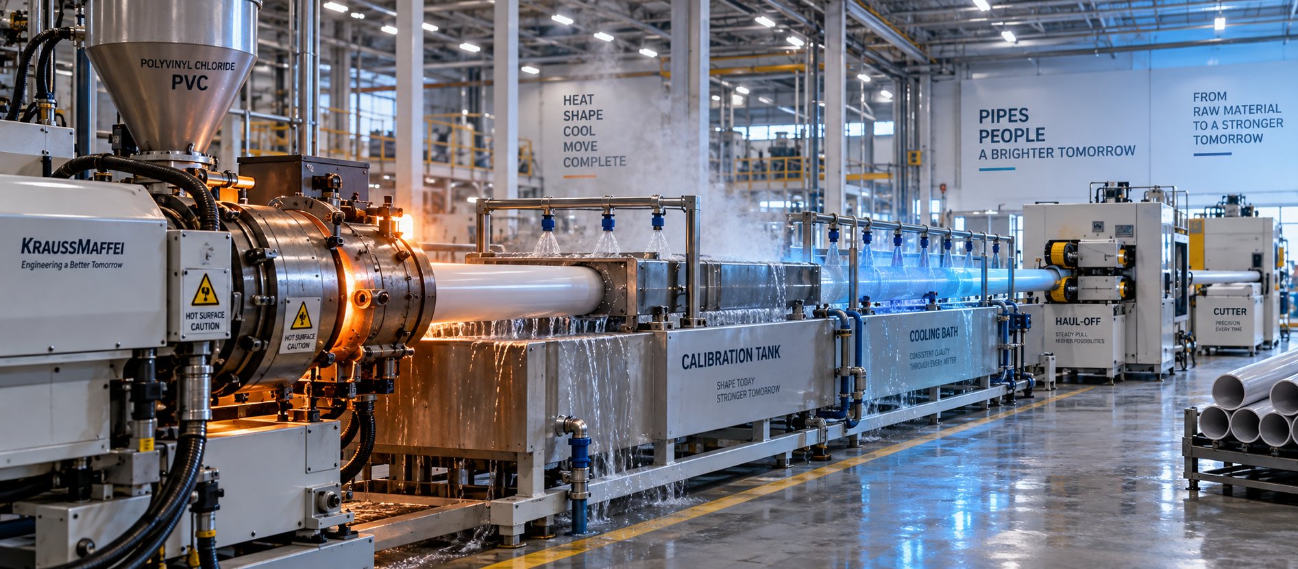
PVC Pipe Making Machine: What No Supplier Will Tell You First
Oct 21, 2026
Learn what a PVC pipe making machine really includes, how each component works, extruder types compared, maintenance schedules, defect fixes, and buying tips.
Read Article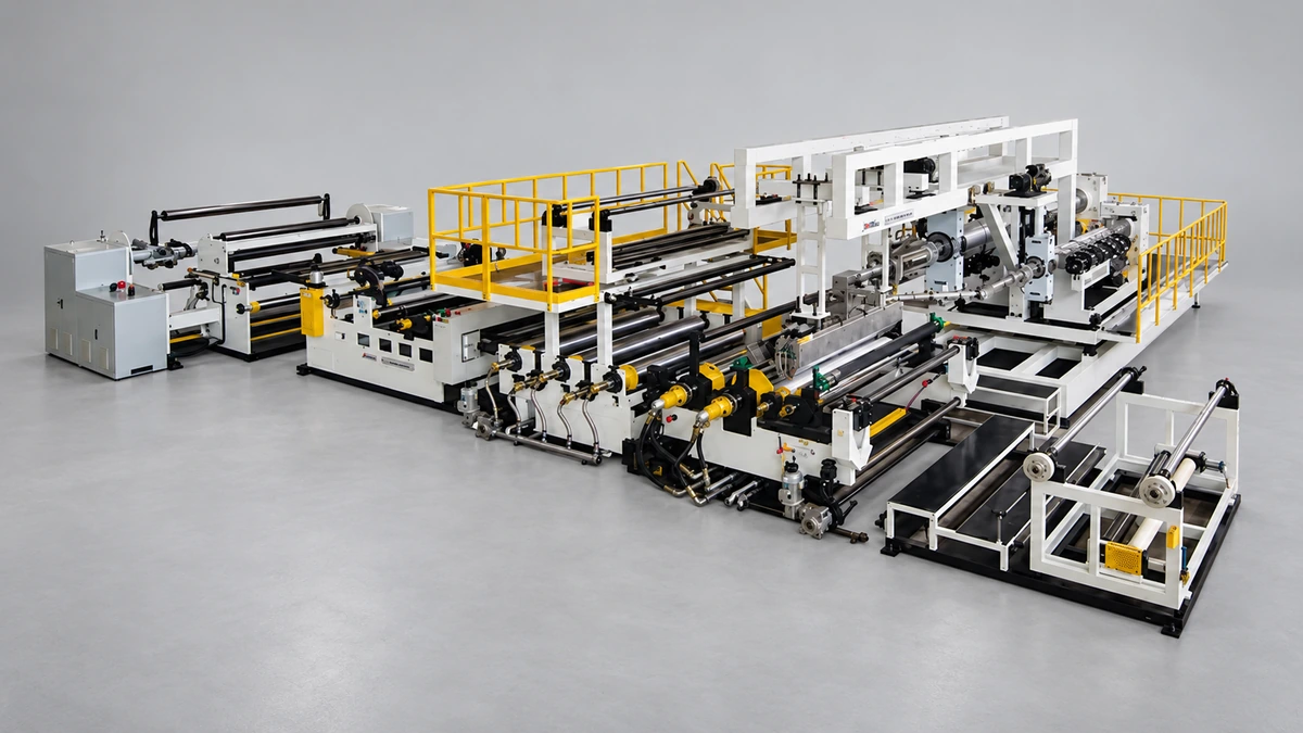
What Your Film Extrusion Machine Datasheet Won't Tell You
Oct 20, 2026
Film extrusion machine guide covering blown vs cast processes, multilayer configurations, screw specs, resin selection, and supplier evaluation for production engineers.
Read Article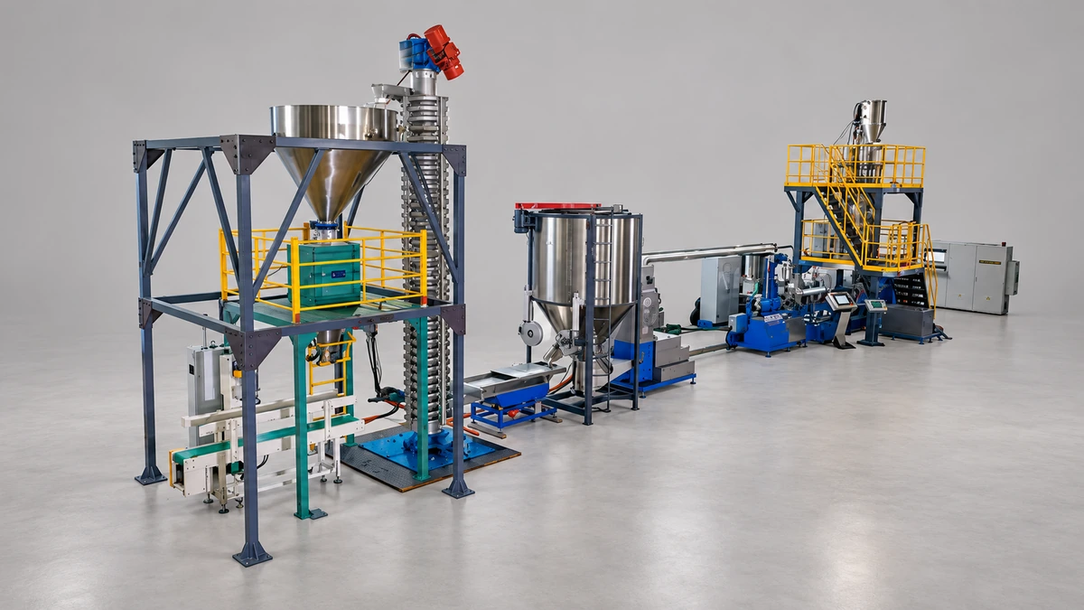
Raw Scrap to Perfect Pellets: Plastic Pelletizing Machine Guide
Oct 19, 2026
Learn how a plastic pelletizing machine converts scrap into uniform pellets. Covers cutting methods, extruder types, quality control, costs, and maintenance.
Read ArticleLooking for something else?
Search by material, symptom or product and jump straight to the relevant page.
These are navigation suggestions based on keyword matching — not a quotation, not a delivery commitment, and not a substitute for engineering review. Final specification is confirmed by our engineers against your drawings and processed material.
Need help with screw barrel selection?
Share your machine model, processed material and application. Our team can help with pricing and technical support.