

What Is Polymer Processing and Why It Matters
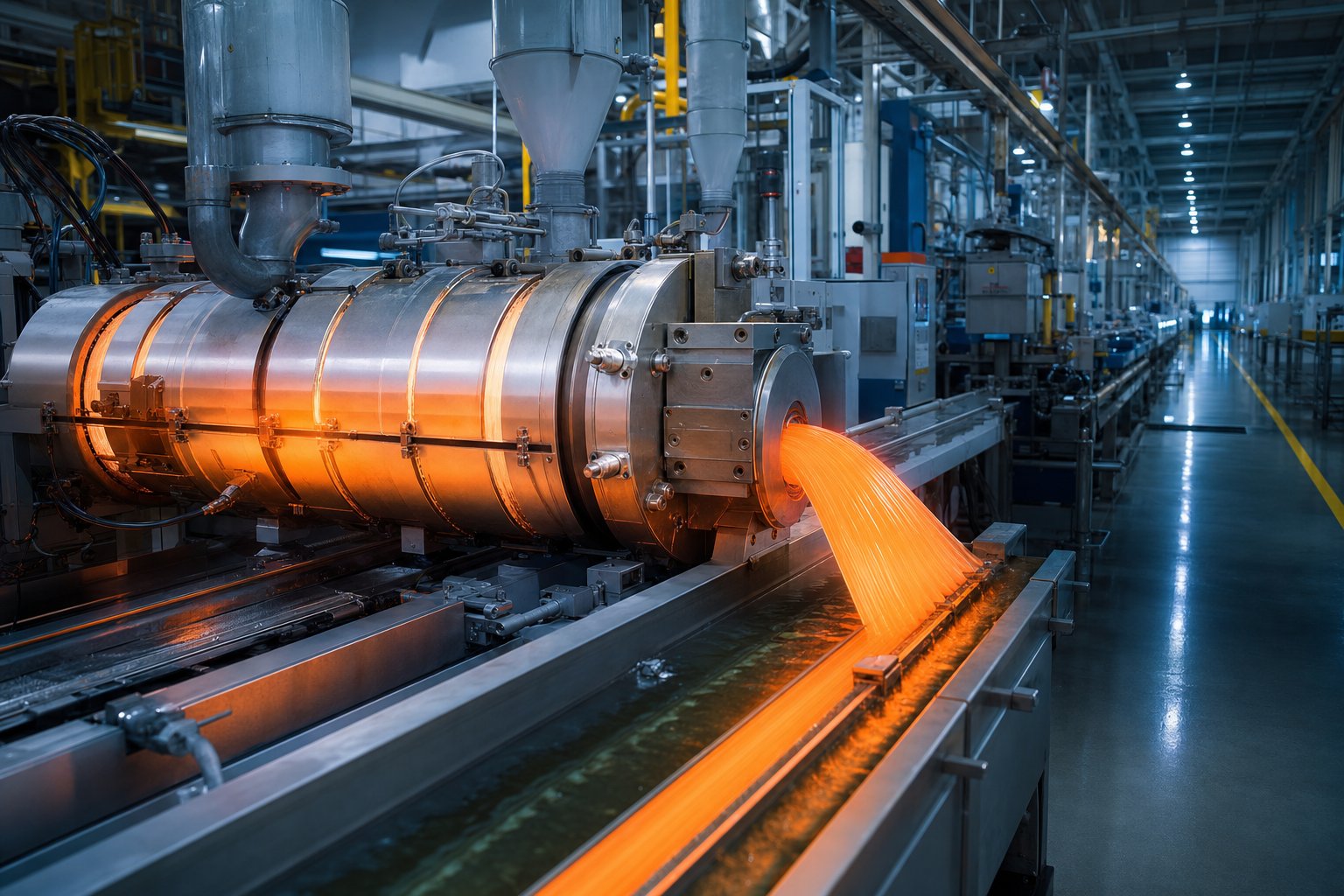
Imagine holding a simple plastic pellet between your fingers. It looks unremarkable - a tiny, uniform granule with no obvious purpose. Yet that pellet is the starting point for everything from automotive dashboards to medical tubing, food packaging films, and structural building pipes. The bridge between raw resin and a functional product? That is polymer processing.
Polymer processing refers to the set of manufacturing techniques used to transform raw polymer materials - typically in the form of pellets, granules, or powders - into finished or semi-finished products through controlled thermal, mechanical, and rheological manipulation. Common methods include extrusion, injection molding, blow molding, thermoforming, and rotational molding.
This definition matters because it draws a clear boundary. The term is often confused with polymerization itself, but these are fundamentally different stages of the manufacturing pipeline. Understanding the distinction is critical for anyone working in plastics engineering, product design, or materials procurement.
Defining Polymer Processing and Its Industrial Scope
At its core, this discipline involves changing a polymer's physical state - heating it into a melt or viscoelastic condition, shaping it through dies, molds, or forming tools, and then cooling or curing it into a stable structure. The University of Michigan's Visual Encyclopedia of Chemical Engineering describes it as "creating structures using polymers by changing their viscosity and rheological properties and shaping them." Every technique in the field revolves around that principle: control the flow, control the form.
The industrial scope is vast. Lightweight polymers reduce fuel consumption in automotive applications. Biocompatible plastics enable sterile medical packaging and implantable devices. Flexible films and rigid containers preserve food and protect consumer goods. Weather-resistant formulations strengthen construction piping and insulation systems. Each of these outcomes depends not just on choosing the right polymer, but on processing it correctly.
How Polymer Processing Differs from Polymerization
So what is the polymerization process, and where does it end? Polymerization is the upstream chemical reaction - the step where small monomer molecules bond together to form long polymer chains through addition or condensation reactions. It is the chemistry that creates the material. Processing, by contrast, is the engineering that shapes it.
Think of it this way: polymerization produces the resin. Processing turns that resin into a pipe, a bottle cap, or a sheet of packaging film. The two stages sit in sequence within the broader manufacturing pipeline:
- Polymer production (synthesis): Monomers undergo polymerization to create raw polymer material, which is then compounded and pelletized.
- Primary processing: Pellets or powders are melted and shaped into products through extrusion, molding, thermoforming, or similar techniques.
- Secondary and tertiary processing: Finished forms undergo additional operations like printing, welding, machining, surface treatment, or assembly.
This hierarchy sets the stage for everything that follows. Whether you work in extrusion, injection molding, blown film, or additive manufacturing, your daily decisions - temperature profiles, screw speeds, cooling rates, tooling configurations - all fall within the processing domain. And those decisions hinge on something even more fundamental: the physical and thermal properties baked into the polymer during its production.
Polymer Properties That Dictate Processing Decisions
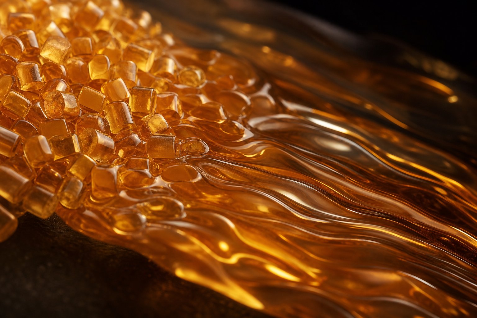
Those physical and thermal properties baked into a polymer during synthesis do not simply live in a datasheet. They dictate everything - which machine you run, what temperatures you set, how fast you pull product off the line, and whether your output meets spec or ends up as scrap. For anyone working in polymer engg, bridging the gap between material science and shop-floor reality starts here.
Molecular Structure and Its Impact on Processability
Four properties form the decision framework for selecting and tuning any polymer processing technique:
- Molecular weight distribution (MWD): Polymers with a broad MWD flow more easily at lower shear rates, making them forgiving during extrusion. Narrow distributions provide more uniform mechanical properties in finished parts but demand tighter parameter control. The question of what process builds polymers into chains with specific MWD profiles is answered upstream during polymerization, yet the consequences land squarely on the processing floor.
- Crystallinity: Semi-crystalline polymers like HDPE and nylon have a defined melting temperature where crystalline regions dissolve. You must exceed this temperature to process them. Amorphous polymers like polycarbonate and polystyrene soften gradually above their glass transition temperature. This difference changes how you design cooling systems and determines shrinkage behavior.
- Glass transition temperature (Tg): Below Tg, amorphous regions become rigid and brittle. Above it, molecular chain segments gain mobility. As Linseis thermal analysis research explains, the cooling rate has a decisive influence on the glass transition temperature - faster cooling raises Tg, which directly impacts part dimensional stability and residual stress.
- Thermal degradation temperature: This is your ceiling. Every degree you add above the recommended processing window risks chain scission, discoloration, or outgassing. The practical processing window sits between the melting point (or Tg for amorphous resins) and the onset of degradation - sometimes a range of just 30-50 degrees Celsius for sensitive materials like PVC or PVDF.
These four properties together define the available parameter window. A department of polymer science and engineering might study them in isolation, but on a production line, they interact simultaneously. A high-crystallinity polymer with a narrow degradation window demands precision barrel temperature control and consistent throughput - there is no room for drift.
Understanding Melt Flow Index as a Processing Guide
If molecular structure defines the boundaries, melt flow index (MFI) is the quick-reference guide practitioners reach for first. Measured in grams per 10 minutes under standardized temperature and load, MFI tells you how easily a polymer flows when melted. Lower values indicate higher viscosity (longer chains, more entanglement); higher values mean the melt moves freely.
Why does this matter on the floor? Because MFI directly influences equipment selection, die geometry, and screw speed settings. A low-MFI resin needs higher pressures to push through a die - try running it at parameters designed for a high-flow grade, and you will get incomplete fills, excessive motor load, or melt fracture.
The table below illustrates how MFI ranges guide technique selection, using polypropylene as a reference polymer:
| MFI Range (g/10 min) | Suitable Processing Method | Typical Products | Key Processing Consideration |
|---|---|---|---|
| 0.3 - 2 | Blow molding | Bottles, tanks, hollow containers | High melt strength needed for parison stability |
| 2 - 5 | Pipe and profile extrusion | Pipes, window frames, decking | Balanced viscosity for shape retention at die exit |
| 3 - 6 | Fiber spinning / film extrusion | Monofilament, blown film | Uniform draw-down ratio and consistent melt tension |
| 8 - 15 | Injection molding | Housings, connectors, containers | Fast cavity fill at lower injection pressure |
| 15 - 30+ | Thin-wall molding / spunbond | Thin containers, non-woven fabrics | Ultra-high flow for complex or thin geometries |
Data adapted from SpecialChem's MFI processing guide, which notes that polypropylene with an MFI of 3.6 g/10 min suits monofilament spinning, while grades at 18 g/10 min serve spun-bonded fabric production. One important caveat: two polymers with identical MFI values will not necessarily behave the same under processing conditions, since MFI does not capture long-chain branching, shear-thinning behavior, or pressure-dependent viscosity changes. Treat it as a starting filter, not the final answer.
Moisture Sensitivity and Pre-Processing Requirements
Imagine running a perfectly tuned extrusion line - temperatures optimized, screw speed dialed in, die geometry matched to your resin grade. Then bubbles appear in your extrudate. Surface defects. Inconsistent mechanical properties. The culprit? Moisture that was never removed before processing.
Hygroscopic polymers - materials like nylon (PA), polycarbonate (PC), PET, and TPU - absorb moisture from ambient air into their molecular structure. This is not surface condensation you can wipe away. The water molecules bond within the polymer matrix and, when heated during processing, cause hydrolysis that breaks polymer chains, leading to reduced viscosity, weakened tensile strength, and visible defects like splay marks or blistering.
The consequences are measurable and costly:
- Viscosity instability: Excess moisture alters the resin's effective MFI during processing, making parameter settings unreliable from batch to batch.
- Mechanical degradation: Chain scission from hydrolysis permanently reduces impact strength, elongation, and fatigue performance.
- Surface quality failures: Bubbles, silver streaks, and rough textures that cannot be corrected downstream.
Proper drying protocols are non-negotiable for these materials. Nylon 66, for example, requires four to six hours of desiccant drying at 80-100 degrees Celsius. Under-drying leaves residual moisture; over-drying or excessive temperatures cause oxidative degradation, brittleness, and color shifts. The window is specific and must be followed precisely.
Non-hygroscopic polymers like polyethylene and polypropylene do not absorb moisture internally, but surface condensation can still cause cosmetic issues. A brief hot-air preheat cycle is typically sufficient for these materials.
The takeaway for processing teams: material preparation is not separate from processing - it is the first processing step. Every property discussed here, from Tg and crystallinity to MFI and moisture content, either expands or narrows the window within which your equipment can produce consistent, defect-free output. And that raises the next practical question: how do upstream production methods - the polymerization chemistry and compounding steps that happen before resin ever reaches your hopper - predetermine what you can and cannot achieve on your processing line?
How Polymers Are Produced Before Processing Begins
The resin sitting in your hopper did not appear from nowhere. Its molecular architecture - chain length, branching, crystallinity, and residual additive content - was locked in during polymer production, well before it reached your facility. Understanding these upstream steps is not academic trivia. It directly explains why one batch runs smoothly and another causes headaches on the same machine with the same settings.
To explain the process of polymerization in practical terms: monomers (small, reactive molecules) are chemically bonded into long repeating chains through controlled reactions. The two fundamental pathways - addition and condensation - produce different chain structures, and the industrial method used to carry out those reactions determines the physical form and purity of the final resin.
Addition and Condensation Polymerization Fundamentals
In addition polymerization, monomers containing carbon-carbon double bonds open up and link end-to-end without releasing any byproduct. The chain grows rapidly from a reactive center - a free radical, cation, or anion - and the result is a polymer with the same elemental composition as its monomer. Polyethylene, polypropylene, PVC, and polystyrene all form through this route. Because no small molecules escape during the reaction, addition polymers tend to achieve high molecular weights quickly, yielding resins with excellent melt strength for extrusion and blow molding.
Condensation polymerization works differently. Here, monomers with two or more functional groups react in a step-growth fashion, releasing a small byproduct - typically water, methanol, or hydrogen chloride - at each linkage. As polymer chemistry research explains, this deliberate process builds polyesters, polyamides (nylons), and polycarbonates with precise density and thermal tolerance. The tradeoff? Condensation polymers require careful removal of byproducts to push the reaction toward high molecular weight, and residual moisture sensitivity often carries over into the processing stage.
From Reactor to Pellet - The Production Pipeline
Regardless of polymerization chemistry, industrial polymer production uses one of several general methods of polymer production to manage heat, viscosity, and product recovery. Each method yields a different material form suited to specific downstream processing routes:
- Bulk polymerization: Only monomer and initiator are present - no solvent or water phase. This produces high-purity resins but presents heat removal challenges at scale. Industrial examples include PMMA, high-pressure LDPE, and crystal polystyrene. The output is typically melt-extruded directly into pellets or cast sheets.
- Suspension polymerization: Monomer droplets are dispersed in water with mechanical agitation, producing uniform beads or granules. PVC, expandable polystyrene, and SAN copolymers are commonly made this way. The bead form is convenient for direct feeding into extruders and molding machines.
- Solution polymerization: Monomer and catalyst dissolve in a solvent, allowing precise temperature control. This route produces HDPE, LLDPE, polyacrylonitrile, and aromatic polyamides. The solvent must be stripped afterward, and the polymer is typically recovered as flakes or pelletized from a melt.
- Emulsion polymerization: Monomers form tiny particles in an aqueous emulsion stabilized by surfactants. The result is a latex - a colloidal dispersion - used directly in coatings, adhesives, and rubber applications. Styrene-butadiene rubber and nitrile rubber are produced this way. When solid pellets are needed, the latex is coagulated and dried.
The sequential journey from raw chemistry to processable material follows a consistent pipeline:
- Monomer synthesis and purification: Petroleum or bio-based feedstocks are cracked, distilled, or fermented into pure monomers.
- Polymerization reaction: Monomers undergo addition or condensation reactions in reactors optimized for heat transfer, mixing, and molecular weight control.
- Product recovery and drying: The polymer is separated from solvents, water, or unreacted monomer through filtration, centrifuging, or devolatilization.
- Compounding and pelletization: The base resin is melt-blended with stabilizers, colorants, fillers, or processing aids in a twin-screw extruder, then strand-cut or underwater-pelletized into uniform granules.
- Primary processing: Pellets enter extrusion lines, injection molding machines, or other forming equipment to become finished products.
Why does this matter to you as a processor? Because choices made at steps one through four - catalyst type, polymerization method, molecular weight targets, additive packages - predetermine the MFI, crystallinity, thermal stability, and moisture behavior you inherit. A PVC resin produced by suspension polymerization arrives as free-flowing powder with specific particle size distributions that affect how it feeds into your extruder. An HDPE from solution polymerization carries different branching characteristics than one made via gas-phase processes, altering die swell and cooling behavior on your line.
The critical insight: polymer production and polymer processing form a continuous chain of cause and effect. You cannot fully optimize downstream parameters without understanding what upstream decisions delivered to your material. And with that foundation in place - knowing both what your resin is and how it came to be - the real question becomes which processing technique best converts that material into your target product geometry, at the right volume, and at competitive cost.
Primary Processing Techniques Compared
Geometry, volume, and cost - those three factors ultimately funnel every polymer manufacturing decision toward one specific technique. But the landscape of available methods is broad, and each operates on fundamentally different mechanics. A hollow bottle demands a different approach than a rigid pipe, and a precision gear requires different tooling logic than a large water tank. Understanding how are polymers manufactured into such diverse forms requires a clear look at each primary method side by side.
Extrusion Processing for Pipes, Profiles, Films, and Sheets
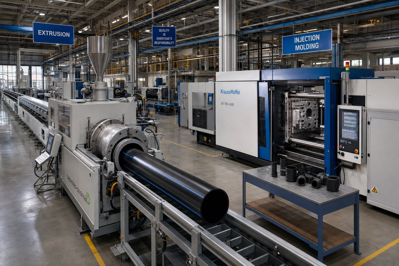
Extrusion stands as the highest-volume continuous process in polymer manufacturing. The principle is straightforward: a rotating screw conveys, melts, and pressurizes polymer within a heated barrel, then forces the melt continuously through a shaped die. What exits that die - a pipe, a window profile, a flat sheet, or a thin film - depends entirely on die geometry and downstream cooling equipment.
The process never pauses. Unlike molding, where each cycle produces a discrete part, extrusion produces indefinite lengths of product. That continuity delivers exceptional material throughput and low per-unit cost for products with uniform cross-sections.
Two screw configurations dominate. Single-screw extruders handle straightforward melting and conveying of pre-compounded pellets - think PE pipe, PVC profiles, and blown film. Twin-screw extruders, particularly co-rotating intermeshing designs, excel where intensive mixing is required: compounding masterbatches, processing recycled blends with inconsistent properties, or incorporating high filler loadings. As Jim Frankland explains in Plastics Technology, the twin can transfer the entire channel of polymer from one screw to the other multiple times, permitting full-channel mixing - something a single screw simply cannot replicate due to inherent velocity stratification in its channel.
Typical extrusion products include PVC drainage pipes, HDPE water mains, uPVC window frames, polyethylene agricultural films, ABS sheets for thermoforming, and WPC decking profiles. Granulation lines also use extruders to pelletize compounded materials for downstream molding operations.
Injection and Blow Molding Mechanics
Injection molding is the workhorse for discrete, complex parts at high volumes. Molten polymer is injected under high pressure into a closed steel mold, packed to compensate for shrinkage, cooled until dimensionally stable, then ejected. Cycle times can drop below ten seconds for thin-wall packaging. The polymer molding process here delivers the tightest tolerances, finest surface detail, and broadest material compatibility of any technique - supporting everything from ABS and polycarbonate to nylon, POM, and TPU.
The tradeoff? Tooling is expensive. Multi-cavity steel molds with hot runner systems represent significant capital investment, justified only at production volumes where amortization drives unit cost below alternatives.
Blow molding takes a different path to create hollow shapes. A molten tube (parison) or injection-molded preform is inflated with compressed air inside a mold cavity. Extrusion blow molding produces HDPE drums and detergent bottles. Stretch blow molding biaxially orients PET molecules to create lightweight bottles with excellent clarity and gas barrier properties. The limitation? Wall thickness uniformity depends on parison control, and fine geometric features are difficult to achieve.
Thermoforming, Rotational, and Compression Methods
Thermoforming heats a pre-made plastic sheet to its softening point, then stretches it over or into a mold using vacuum, pressure, or mechanical assist. It suits large panels, food trays, appliance liners, and vehicle interior components at medium volumes. Tooling costs remain low compared to injection molding, making it attractive for parts where ultra-tight tolerances are not required.
Rotational molding fills a different niche entirely. Polymer powder - almost always polyethylene - is placed inside a mold that rotates biaxially in an oven. The powder melts and coats the mold interior uniformly, creating large, seamless hollow structures like water tanks, kayaks, and playground equipment. No internal pressure is applied, so residual stress is minimal and tooling costs stay low. The penalty is cycle time: rotomolding is the slowest primary technique.
Compression molding handles thermoset materials that injection molding cannot. A pre-measured charge of SMC (sheet molding compound), BMC (bulk molding compound), or rubber is placed into a heated mold cavity and compressed under hydraulic pressure. The material flows to fill the cavity and then undergoes irreversible chemical curing. This produces thick, high-strength structural parts - automotive panels, electrical enclosures, and composite brackets - with excellent heat resistance.
Cross-Technique Comparison at a Glance
Choosing between these methods means weighing multiple factors simultaneously. The table below consolidates the trade-offs into a single reference:
| Technique | Process Principle | Suitable Polymers | Typical Products | Volume Suitability | Tooling Cost | Part Complexity |
|---|---|---|---|---|---|---|
| Extrusion | Continuous melt forced through shaped die | PE, PP, PVC, ABS, PET, TPU | Pipes, profiles, films, sheets, filament | High (continuous) | Low-Medium | Low (2D cross-section) |
| Injection Molding | High-pressure melt injection into closed mold | ABS, PC, PP, PA, POM, PBT, TPU | Housings, gears, connectors, medical parts | High (10K+ parts) | High | Very High (complex 3D) |
| Blow Molding | Parison or preform inflated with air inside mold | HDPE, LDPE, PP, PET, PVC | Bottles, containers, tanks, ducts | Medium-High | Medium | Medium (hollow shapes) |
| Thermoforming | Heated sheet shaped over mold by vacuum/pressure | HIPS, ABS, PETG, PVC, PC, PMMA | Trays, panels, enclosures, liners | Low-Medium | Low | Low-Medium (shell forms) |
| Rotational Molding | Powder melts inside biaxially rotating heated mold | LLDPE, HDPE, XLPE, PA11/12 | Tanks, kayaks, bins, playground items | Low | Low | Low (large hollow) |
| Compression Molding | Charge pressed and cured in heated matched mold | SMC, BMC, phenolics, rubber | Structural panels, electrical parts, gaskets | Low-Medium | Medium | Medium (thick sections) |
Notice the pattern: as part complexity and tolerance demands increase, so does tooling investment. Extrusion delivers the lowest cost per kilogram for continuous profiles, but it cannot produce three-dimensional shapes. Injection molding handles almost any geometry, but justifying that tooling requires volume. Rotomolding and thermoforming fill the gap where large parts or moderate runs make expensive steel molds impractical.
Each technique also imposes its own parameter universe - temperature profiles, pressures, speeds, and cooling strategies that must be tuned to the specific polymer running through the equipment. Selecting the right method is only half the challenge. The other half is optimizing the parameters within that method to achieve consistent, defect-free output at maximum efficiency.
Process Parameter Optimization for Consistent Output
Selecting the right technique gets you to the starting line. Crossing the finish line - with consistent dimensions, clean surfaces, and reliable mechanical properties - depends on how precisely you dial in your polymer process parameters. Temperature, pressure, screw speed, and cooling rate form an interconnected system where adjusting one variable shifts everything else. Master these interactions, and you will turn a capable machine into a profitable one.
Temperature Profile Optimization Across Barrel Zones
Every extruder barrel is divided into multiple heating zones, each serving a distinct function aligned with the screw sections beneath it. Getting these zone temperatures right is not guesswork - it follows directly from the polymer's thermal behavior.
The principle is straightforward: initial barrel zones covering the solids conveying section need temperatures that maximize the forwarding friction between the resin and the barrel wall. For semicrystalline resins like polyethylene, extrusion research by Mark Spalding at Dow recommends starting at the melting temperature (Tm) plus 50 degrees Celsius. For amorphous resins like HIPS (Tg of 105 degrees Celsius), an initial setting around 155 degrees Celsius provides a solid baseline. The barrel zones over the melting section then run 30 to 50 degrees Celsius higher than the solids conveying zones, because melting flux - the rate at which solid polymer converts to melt at the barrel wall - increases with temperature. LDPE, for instance, shows a 20% increase in melting flux when barrel temperature rises from 190 to 250 degrees Celsius.
This often produces what experienced operators call a "hump" temperature profile: relatively low feed zone temperatures, peak temperatures in the melting section, and slightly reduced temperatures over the metering and mixing zones. Why reduce temperature at the end? Because the metering section's job is to stabilize discharge temperature, and pushing it too high risks thermal degradation. As a practical rule of thumb, decreasing barrel zone temperatures by 10 degrees Celsius over the metering section lowers discharge melt temperature by roughly 2 to 3 degrees Celsius.
For the production of engineering polymers like polycarbonate or PA66, the processing window between melting and degradation can be extremely narrow. These materials demand precise multi-zone PID control and frequent verification with immersion melt thermocouples at the die - because barrel setpoint temperatures and actual melt temperatures are not the same thing. Screw design, barrel wear, and energy dissipation from shear all create gaps between what the controller displays and what the polymer actually experiences.
PVC adds another layer of complexity. Its thermal sensitivity means shorter L/D ratios and lower barrel temperatures are typically preferred to avoid degradation. Push the temperature too high or allow residence time to stretch, and the material releases hydrochloric acid, corroding equipment and ruining the product.
Screw Speed, Pressure, and Output Rate Relationships
Screw speed (measured in RPM) is the primary lever for controlling output rate - but it is not a simple "faster equals more" relationship. Higher RPM increases throughput, yes. It also increases shear heating, which raises melt temperature independently of barrel heater settings. For shear-sensitive polymers, this additional heat can push you past the degradation threshold before your barrel thermocouples even register a problem.
The interaction between MFS speed (melt flow speed through the die), screw RPM, and back pressure defines your operating envelope. Back pressure builds from die resistance and downstream pull. Increase it, and you improve mixing quality and melt homogeneity. Increase it too much, and you restrict throughput, raise melt temperature, and create excessive motor load. The balance point depends on your specific die geometry, polymer viscosity, and target output rate.
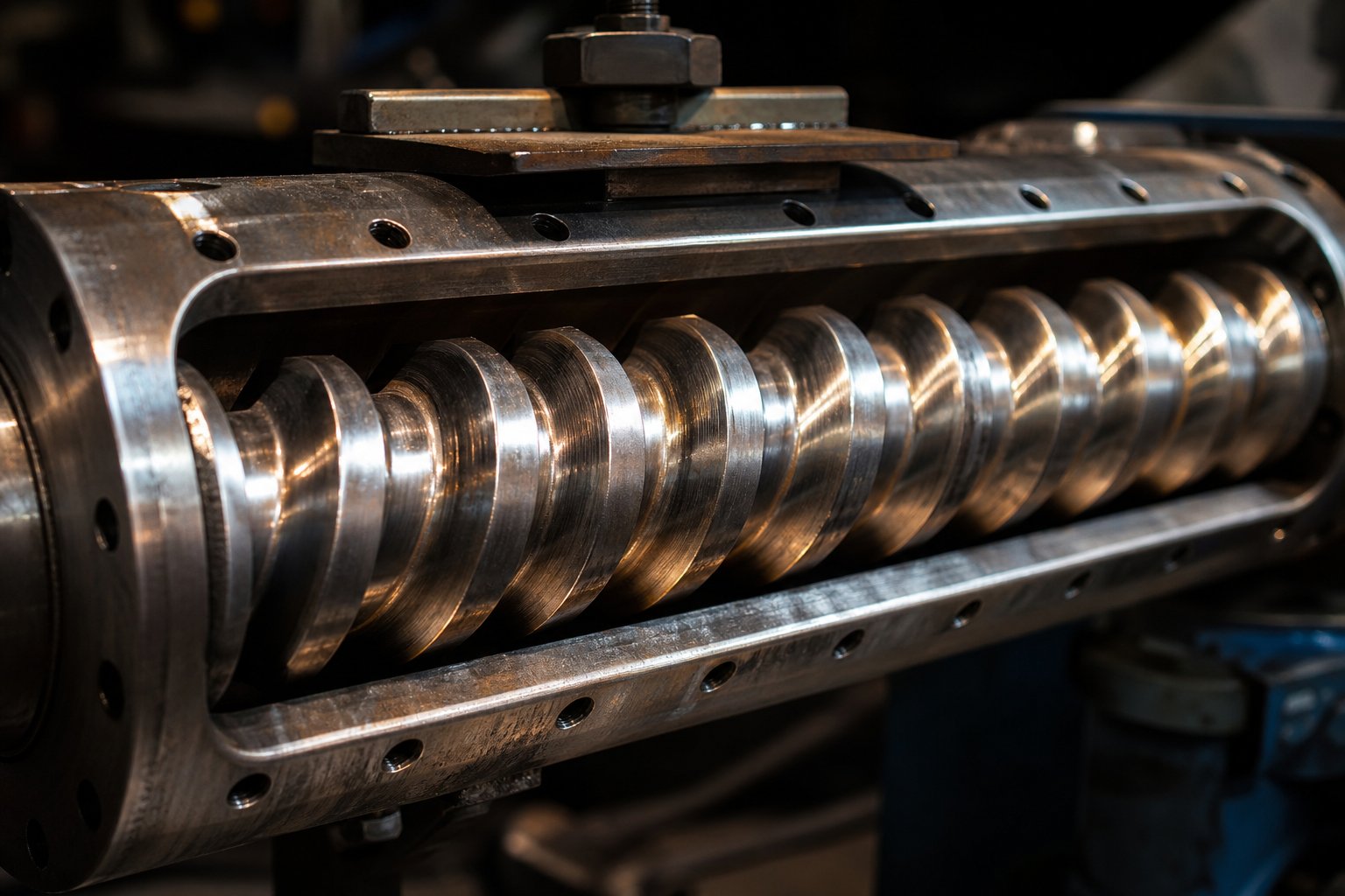
Here is where screw geometry becomes the hidden variable that most operators inherit but rarely question. Three parameters matter most:
- L/D ratio: Standard single-screw extruders range from 20:1 to 30:1. Higher L/D ratios improve plasticization and enable higher screw speeds, but they also increase power consumption, manufacturing complexity, and the risk of shaft deflection in smaller-diameter screws.
- Compression ratio: This is the ratio of the feed section groove volume to the metering section groove volume. Polyethylene typically needs a compression ratio of 3:1 to 4:1 to achieve thorough melting and densification. ABS, by contrast, requires only 1.6:1 to 2.5:1 due to its different bulk density and thermal characteristics. A mismatched compression ratio leads directly to incomplete melting or excessive shear degradation.
- Flight depth: Deeper flights in the feed section improve solids conveying capacity, but excessive depth weakens the screw structurally and disrupts uniform heat transfer. Shallower metering flights increase shear rate - beneficial for mixing, detrimental if the polymer is heat-sensitive.
These geometric parameters are not adjustable during a run. They are locked into the screw barrel hardware you have installed. That reality makes screw selection one of the most consequential decisions in any extrusion operation - and it is why matching screw geometry to your specific polymer and product requirements matters so much. For teams running diverse product lines across pipe, profile, film, sheet, WPC, or granulation equipment, NANHAIYA's custom screw barrel solutions provide a practical resource for specifying and sourcing replacement screw barrels engineered for specific polymer families and output targets, rather than relying on generic configurations that compromise performance.
Worn screws compound the problem. As flight tips erode, the clearance between screw and barrel increases beyond the optimal 0.1 to 0.6 mm range. The result is increased backflow, melt leakage, pressure fluctuations, and localized overheating from added friction. Output drops. Consistency degrades. If your extruder suddenly develops pressure cycling or dimensional drift without any parameter changes, check screw and barrel wear first.
Cooling Rate Control and Cycle Time Reduction
What happens after the melt exits the die is just as critical as what happens inside the barrel. Cooling rate controls crystallization behavior in semicrystalline polymers, residual stress in amorphous ones, and dimensional accuracy in everything.
Cool too fast, and you lock in high residual stresses that manifest as warpage, cracking, or dimensional instability during service. Cool too slowly, and you extend cycle times, reduce throughput, and in semicrystalline materials, promote excessive crystallinity that can make parts brittle. For injection molding, cooling typically accounts for 60 to 80 percent of the total cycle time - making it the single biggest lever for productivity improvement.
In extrusion, cooling takes different forms depending on the product. Pipe extrusion uses calibration sleeves with vacuum sizing followed by spray or immersion cooling tanks. Film extrusion relies on chill rolls or air rings. Profile extrusion employs calibration tables with controlled water contact. In every case, the cooling system must remove heat symmetrically. Uneven cooling creates differential shrinkage - and differential shrinkage creates warped product.
Die temperature also plays a role that is easy to overlook. Uneven die temperatures create flow distribution imbalances, producing gauge variation in films and wall thickness inconsistencies in pipes. Monitoring and balancing die zone temperatures is a straightforward correction that eliminates a surprising number of dimensional defects.
Troubleshooting Common Parameter-Related Defects
Even with careful setup, defects appear. The key is tracing each defect back to the specific parameter deviation that caused it. Here are the most common issues and their corrective strategies:
- Melt fracture (spiral patterns or gross surface distortion): Reduce extrusion rate or increase die temperature to lower melt viscosity at the die land. Widening the die gap or using a polymer processing aid can also reduce the shear stress below the critical fracture threshold.
- Shark skin (fine ridges on the extrudate surface): This occurs at the die exit from excessive surface stress. Lower the output rate, raise the die lip temperature, or apply a fluoropolymer-based processing aid to reduce surface drag. Adjusting to a resin grade with a slightly higher MFI can also help.
- Die swell (extrudate expands beyond the die dimensions): Increase the die land length to allow more stress relaxation before exit. Reducing screw speed decreases the elastic memory stored in the melt. For high die swell polymers, compensating die geometry during tooling design is often more practical than chasing parameter corrections.
- Thermal degradation (yellowing, brown specks, or burnt smell): Reduce barrel temperatures in the metering zone and verify residence time is not excessive. Check for dead spots in the die or adapter where material can stagnate and overheat. Inspect the screw for worn flights that create localized friction buildup.
- Flow surging (periodic output fluctuations): Often caused by improper solids conveying - barrel feed zone temperature may be too high, reducing the friction differential needed to push material forward. Lower the feed zone temperature in 10-degree increments and monitor rate stability. Also verify that the feed casing temperature is maintained at 40 to 60 degrees Celsius to prevent pellet bridging.
- Unmelts (solid fragments in extrudate): Increase melting zone barrel temperatures to boost melting flux. If the problem persists, the screw's compression ratio or L/D ratio may be insufficient for the material - a screw design change rather than a parameter adjustment is the permanent fix.
Notice a pattern in this list? Nearly every defect traces back to an imbalance between thermal energy, mechanical shear, and residence time. Adjusting parameters corrects the symptom. Matching screw geometry, barrel condition, and die design to your specific polymer prevents the symptom from recurring.
Parameter optimization delivers measurable returns - less scrap, faster cycles, lower energy consumption, and more consistent product quality. But those returns exist within an economic framework that extends well beyond machine settings. Tooling costs, production volumes, material pricing, and capital amortization all shape the profitability equation, and they influence technique selection just as powerfully as any temperature profile or screw speed setting.
Economic Factors in Processing Technique Selection
A perfectly optimized temperature profile means nothing if the technique itself does not make financial sense for your production volume. Every day, engineers and operations managers face the same fundamental question: which method delivers acceptable parts at the lowest total cost for the quantities we actually need? The answer shifts dramatically depending on whether you are producing 50 prototypes, 5,000 units for a regional launch, or 500,000 parts annually for a global supply chain.
This is where the polymer processing industry often stumbles. Technical articles cover the mechanics of extrusion, molding, and thermoforming in detail, but rarely address the economic logic that determines which technique a manufacturer should actually invest in. Yet for most businesses, the cost decision comes before the parameter decision.
Production Volume and Technique Cost-Effectiveness
The economics of how polymers are produced into finished goods follow a consistent pattern: every technique carries a combination of upfront tooling investment and per-unit production cost. As Fictiv's manufacturing cost analysis frames it, the total cost formula is straightforward:
Total Cost = Tooling (NRE) + (Unit Cost x Quantity) + Secondary Operations + Logistics/Quality Risk
That formula explains why a $10,000 injection mold makes perfect sense for 20,000 parts - adding just $0.50 per unit in tooling amortization - but is irrational for 100 parts, where tooling alone contributes $100 each. The crossover point where high-tooling methods overtake low-tooling alternatives defines your technique selection threshold.
Consider the cost curves. 3D printing and CNC machining maintain relatively flat per-unit costs regardless of volume - no expensive molds or dies required. Thermoforming and extrusion carry modest tooling and drop in unit cost steadily as volumes rise. Injection molding and compression molding start with the highest tooling spike but plunge to the lowest unit costs once production scales into thousands or tens of thousands of parts.
The table below maps these relationships across practical volume ranges:
| Production Volume | Recommended Techniques | Relative Unit Cost | Typical Tooling Lead Time | Key Economic Factor |
|---|---|---|---|---|
| Prototype (1-50 units) | 3D printing, CNC machining | High | Days to 1 week | Zero tooling investment; speed to first part |
| Low (50-1,000 units) | Thermoforming, rotational molding, soft-tool injection molding | Medium-High | 2-4 weeks | Low tooling cost offsets higher per-unit cost |
| Medium (1,000-10,000 units) | Extrusion, aluminum-tool injection molding, blow molding | Medium | 3-6 weeks | Tooling amortization begins reducing unit cost significantly |
| High (10,000+ units) | Steel-tool injection molding, continuous extrusion, compression molding | Low | 4-12 weeks | Tooling fully amortized; unit cost driven by cycle time and material |
Notice the lead time column. Tooling fabrication - not machine time - dominates the schedule for high-volume methods. Building a hardened steel injection mold can take 4 to 12 weeks before a single production part is made. Extrusion dies are simpler and faster to produce, which partly explains why extrusion offers a faster path to volume production for products with uniform cross-sections. Many programs use hybrid strategies to bridge this gap: CNC-machined prototypes for engineering validation, soft aluminum tools for pilot runs, and hardened steel molds only when the design is locked and volume commitments are firm.
Tooling Investment and Amortization Considerations
Tooling cost is not just a line item - it is a strategic commitment. A hardened steel injection mold represents tens of thousands of dollars and weeks of lead time, but it can produce hundreds of thousands of parts with tight tolerances before requiring maintenance. A thermoforming tool costs a fraction of that amount but wears faster and cannot deliver the same dimensional precision. An extrusion die sits somewhere in between: moderately priced, relatively fast to fabricate, and capable of running continuously for extended production campaigns.
The real question is amortization speed. How quickly does your production volume absorb that upfront investment? Imagine two scenarios for manufacturing a polymer housing:
- Scenario A - 2,000 units annually: An aluminum injection mold at $8,000 adds $4.00 per part in tooling cost. A thermoformed version with a $2,500 tool adds $1.25 per part - but the per-unit forming cost is higher, and secondary trimming adds labor. Total cost per part may be comparable, but the thermoforming route delivers parts weeks sooner.
- Scenario B - 50,000 units annually: A hardened steel mold at $35,000 adds just $0.70 per part. Cycle times of 15 to 30 seconds per shot drive unit costs to levels no other technique can match. The mold pays for itself within the first production run.
This amortization logic also explains why the manufacture of polymers into standard commodity products - bottle caps, pipe fittings, electrical connectors - overwhelmingly relies on injection molding and continuous extrusion. At commodity volumes, tooling cost becomes negligible per unit, and the economic competition shifts entirely to cycle time, energy efficiency, and material yield.
How Recycled Polymer Streams Change the Economics
Recycled feedstocks introduce a different cost equation. The raw material is cheaper - post-industrial regrind or post-consumer recyclate can cost 20 to 50 percent less than virgin resin. But that savings comes with processing penalties that erode the margin if you are not prepared for them.
As research published in Polymers documents, recycled plastics suffer from contamination, inconsistent melt flow properties, and progressive molecular weight degradation through each reprocessing cycle. An HDPE blend study cited in the paper found a gradual decline in mechanical performance with each recycling stage, with the most significant drop occurring after the initial step. For PLA/PS blends, apparent viscosity decreased and flow behavior became more sensitive to shear rate and temperature after recycling.
What does this mean economically? You save on material cost but spend more on:
- Sorting and pre-processing: Contaminated or mixed streams require additional cleaning, drying, and separation before they can be fed into processing equipment.
- Parameter adjustment: Inconsistent MFI batch-to-batch means more frequent process tuning, wider tolerance acceptance, and potentially higher scrap rates during changeovers.
- Quality testing: Recycled materials require more rigorous incoming inspection and in-process monitoring to catch degradation-related defects before they propagate through a production run.
- Equipment wear: Contaminants in recycled streams - metal fragments, calcium carbonate residues, incompatible polymer traces - accelerate screw and barrel wear, increasing maintenance frequency and component replacement costs.
The net economics favor recycled streams most strongly in applications with generous tolerance requirements and high material consumption - drainage pipes, landscaping products, pallets, and non-structural packaging. For precision parts or products requiring consistent surface finish, the processing overhead can negate the material savings.
Decision Framework: Dedicated vs. Flexible Equipment Lines
Beyond technique selection, a parallel economic decision looms: should you invest in dedicated equipment optimized for one product, or flexible multi-purpose lines that handle diverse runs?
Dedicated lines - a single-screw extruder permanently configured for HDPE pipe, for example - maximize throughput and minimize changeover losses. Every parameter is locked in. Screw geometry, die tooling, and downstream equipment are all purpose-matched. The economics work beautifully at sustained high volumes. The risk? If demand shifts or the product becomes obsolete, that specialized equipment has limited redeployment value.
Flexible lines trade peak efficiency for versatility. A multi-purpose injection molding cell with quick-change mold systems can switch between products in hours rather than days. An extrusion line with interchangeable dies and modular downstream cooling can serve pipe, profile, and sheet production from the same platform. The unit cost per product is somewhat higher, but the total capital utilization across a diverse product portfolio can be superior.
The decision hinges on five questions practitioners should ask before committing capital:
- What volume do you realistically expect over the next 12 to 24 months - and how confident is that forecast?
- Is the product design stable, or are revisions likely that would require retooling?
- Does the product geometry demand a specific technique, or could multiple methods produce acceptable results?
- Are you processing a single polymer family, or do you need to handle diverse materials with different thermal and rheological profiles?
- Is speed to market or long-term unit cost the more critical competitive factor?
For many processors in the polymer processing industry, the honest answer is a hybrid approach: dedicated high-volume lines for bread-and-butter products, supplemented by flexible capacity for shorter runs, new product introductions, and seasonal demand spikes. That combination balances capital efficiency against market responsiveness - the same tension that drives every manufacturing investment decision.
Sound economics get you to profitability. But profitability means nothing if your output does not meet specification. The most cost-effective technique at the highest volume still fails if parts come off the line warped, undersized, or mechanically deficient. Catching those failures - and tracing them back to their root causes - requires a quality control system as rigorous as the process parameters themselves.
Quality Control and Defect Troubleshooting
A warped pipe that cannot seat into its fitting. A bottle cap with internal voids that cracks under torque. A blown film with fine surface ridges that destroy optical clarity. Each of these failures costs money - in scrap, rework, customer returns, and lost production time. The uncomfortable truth? Most defects are detectable before they leave the plant, and nearly all of them trace back to a specific parameter deviation, material condition, or equipment issue that could have been caught earlier.
Quality control in polymer processing is not a final checkpoint - it is an integrated system that runs parallel to the production process itself. When done well, it closes the loop between what your machine is doing and what your product actually looks like, measures like, and performs like under load.
Mechanical and Dimensional Testing Standards
Every finished polymer product must answer two fundamental questions: does it fit, and will it hold up? Dimensional inspection answers the first. Mechanical testing answers the second.
Dimensional inspection for molded parts typically involves coordinate measuring machines (CMM), optical comparators, or laser scanning systems that compare actual part geometry against CAD models. For extruded products like pipes and profiles, wall thickness gauges, diameter micrometers, and profile projectors verify cross-sectional conformance at regular intervals along the production run. Advanced facilities use X-ray metrology and CT scanning to inspect internal features - wall thickness distribution in blow-molded containers, void detection in thick-section moldings, and fiber orientation in reinforced composites - without destroying the part.
Mechanical testing goes deeper. As polymer testing specialists at Micom Laboratories emphasize, mechanical testing evaluates measurable properties including tensile strength, stiffness, ductility and elongation, flexural behavior, and compressive performance. For polymers specifically, test conditions like strain rate, specimen conditioning, temperature, humidity, and processing history can significantly influence results - meaning that testing must be planned around real service conditions rather than treated as a generic pass/fail exercise.
The most common mechanical tests applied to processed polymer products include:
- Tensile testing (ASTM D638 / ISO 527): Measures how much load the material withstands before failure and how much it elongates. Critical for films, fibers, and any product under sustained pulling forces.
- Impact testing (ASTM D256 / ISO 180): Quantifies energy absorbed during fracture - typically via Izod or Charpy methods. Essential for parts exposed to sudden loading or low-temperature service.
- Flexural testing (ASTM D790 / ISO 178): Evaluates stiffness and strength under bending. Directly relevant for structural profiles, panels, and enclosures.
- Hardness testing (Shore A/D): Measures surface resistance to indentation. Quick and useful for incoming material verification and process consistency checks.
Here is an important nuance that separates routine quality programs from effective ones: polymer properties are sensitive to processing history. A tensile bar cut from a well-packed, properly cooled injection-molded plaque will not behave identically to one from a region near a weld line or gate. Regrind percentage, mold temperature, and cooling time all shift mechanical results. That is why meaningful quality data requires consistent specimen preparation and testing conditions that reflect the actual production process - not idealized laboratory setups.
How Testing Protocols Differ by Product Type
Imagine comparing quality control for a continuous extruded pipe versus a discrete injection-molded connector. The products are fundamentally different in how they are produced, inspected, and validated - and the testing logic must follow suit.
Extruded products like pipes, profiles, and sheets run continuously. You cannot inspect every meter. Instead, quality programs rely on periodic sampling - cutting test specimens at defined intervals (every 30 minutes, every reel change, every new material lot) and performing dimensional checks, hydrostatic burst tests for pressure pipes, or tensile testing on film strips. In-line measurement systems continuously monitor critical dimensions like wall thickness and outer diameter using ultrasonic or laser gauges, flagging deviations in real time before they accumulate into significant scrap volumes.
Discrete molded parts follow a different pattern. Each shot cycle produces a complete part (or set of parts in multi-cavity tools), and quality verification focuses on part-to-part consistency within a production run. First article inspection (FAI) validates that initial samples meet all dimensional and functional specifications. Statistical process control (SPC) then tracks key characteristics - weight, critical dimensions, surface quality - across the run to detect drift before it causes out-of-spec conditions. For multi-cavity molds, cavity-to-cavity comparison is essential: weighing and measuring parts from every cavity under the same shot conditions separates process variation from steel variation, identifying whether a defect is random or locked to a specific mold position.
In-Line Monitoring and Statistical Process Control
Catching defects after they happen is expensive. Catching parameter drift before it produces defects is where modern quality systems earn their return on investment.
In-line monitoring technologies now available across both extrusion and molding include melt pressure sensors at the die, infrared temperature profiling along barrel zones, ultrasonic wall thickness measurement for pipe and tubing, and gravimetric throughput monitoring that detects output rate fluctuations in real time. These sensors feed data into SPC systems that calculate control limits, track trends, and trigger alarms when a parameter begins drifting outside its validated window.
The power of SPC lies in pattern recognition. A single out-of-spec reading might be noise. A gradual upward trend in melt pressure over several hours signals something actionable - perhaps increasing screen pack contamination, progressive screw wear, or a shift in incoming material viscosity. Responding to the trend prevents the defect. Responding only to the final out-of-spec part means scrap has already been produced.
For injection molding, cavity pressure monitoring has become one of the most diagnostic tools available. By placing pressure sensors directly in the mold cavity, processors can monitor fill behavior, packing pressure transfer, and gate freeze timing shot by shot. Deviations in the cavity pressure curve correlate directly with defects: a premature pressure drop indicates short shot risk, an excessively high peak suggests flash potential, and inconsistent curves between cavities reveal flow imbalance or tooling wear.
Tracing Defects Back to Parameter Deviations
When a defect appears, the first instinct is often to start adjusting machine settings. Resist that urge. Effective troubleshooting requires separating process-sensitive defects from those rooted in tooling, material, or part design - because the corrective path is fundamentally different for each.
The following list pairs common defect types with their typical root causes and the parameter adjustments most likely to resolve them:
- Voids (internal bubbles or hollow sections): Usually caused by insufficient packing pressure or premature gate freeze in injection molding. Increase hold pressure and hold time in controlled increments, monitoring part weight until it plateaus. If part weight stabilizes but voids persist in thick sections, the wall thickness ratio or gate size is the physical bottleneck - a design issue, not a process one.
- Warpage (bowed or distorted geometry): Driven by differential cooling, shrinkage imbalance, or ejection stress. Compare part flatness across controlled cooling-time changes before escalating to mold review. Asymmetric rib layouts and uneven wall thickness are frequent design-side contributors that no amount of process tuning can fully correct.
- Sink marks (surface depressions over thick sections): Result from volumetric shrinkage during cooling without adequate melt compensation. Increase hold time, verify gate freeze timing, and review rib-to-wall thickness ratios. A gate freeze study - plotting part weight against hold time - pinpoints whether the gate is sealing before the part is fully packed.
- Weld lines (visible lines where flow fronts meet): Occur when two melt fronts converge at insufficient temperature or pressure. Raising mold temperature or injection speed can improve molecular bonding at the meeting point. If the line crosses a structural feature like a snap fit or screw boss, gate relocation may be necessary to shift the weld to a non-critical area.
- Discoloration (yellowing, brown streaks, or black specks): Indicates thermal degradation from excessive melt temperature, prolonged residence time, or material stagnation in dead spots. Reduce barrel temperatures in the metering zone, verify purging protocols, and inspect for worn screw flights or contaminated hot runner systems.
- Splay (silver streaks on the surface): Most commonly caused by residual moisture in hygroscopic resins. Verify the drying record and material handling history before adjusting any machine settings. As Micom's testing guidance notes, moisture-induced splay reduces impact strength - meaning visual defects are only the surface indicator of deeper mechanical degradation.
- Flash (thin excess material at parting lines): Results from excessive cavity pressure, late velocity-to-pressure transfer, or insufficient clamp force. Reduce packing pressure in controlled steps before assuming the mold needs rework. If flash persists while the part begins to short shot under reduced pressure, parting-line wear or shut-off damage is the real cause.
Notice the recurring principle: adjust one variable at a time, measure the response, and escalate to tooling or design review only when controlled process changes fail to resolve the issue. This disciplined approach - what the industry calls scientific molding methodology - prevents the all-too-common scenario of chasing multiple parameter changes simultaneously, losing track of what actually fixed (or worsened) the problem.
The Role of Polymer Processing Aids in Surface Quality
Some surface defects resist correction through parameter adjustment alone. Melt fracture - also known as sharkskin or orange peel - and die lip buildup are two persistent challenges in extrusion that stem from fundamental polymer-die interactions rather than simple temperature or speed errors.
This is where polymer processing aids earn their place in the formulation. PPAs are functional additives, typically incorporated at low concentrations (hundreds of ppm), that migrate to the polymer-metal interface during extrusion and reduce the frictional drag between the melt and the die wall. The practical results are significant: elimination of melt fracture in blown film, reduction of die lip buildup, and the ability to increase extruder output at the same screw RPM without triggering surface defects.
Traditionally, fluoropolymer-based PPAs have been the industry standard for decades. However, the regulatory landscape is shifting. Per- and polyfluorinated substances (PFAS) - the chemical family that includes fluoropolymer PPAs - face increasing scrutiny from regulators and brand owners due to environmental persistence concerns. The packaging industry, in particular, is actively transitioning toward PFAS-free PPA alternatives that deliver comparable melt fracture elimination and die buildup reduction without the associated regulatory and environmental risk.
For processors, the practical takeaway is straightforward: if you are battling persistent surface defects in film, sheet, or profile extrusion despite optimized temperatures and speeds, a PPA addition may solve the problem more effectively and sustainably than further parameter manipulation. Evaluate candidates based on time-to-clear performance (how quickly the additive eliminates existing melt fracture), die buildup reduction over extended runs, and compatibility with your downstream requirements like printing, sealing, or food-contact compliance.
Quality control, at its best, does more than reject bad parts. It generates the data that connects every defect to its origin - whether that origin sits in the material, the process, the tooling, or the part design itself. That diagnostic capability is becoming even more powerful as the industry integrates digital monitoring, predictive analytics, and real-time feedback systems into production lines - a transformation that is reshaping how processors think about consistency, efficiency, and sustainability across the entire manufacturing operation.

Emerging Trends Reshaping the Processing Landscape
That diagnostic capability - connecting every defect to its root cause through data - is no longer limited to after-the-fact analysis. A fundamental shift is underway in how polymer processing facilities generate, interpret, and act on information. Sensors that once fed simple alarm thresholds now stream continuous data into AI-driven control systems. Virtual replicas of entire production lines simulate parameter changes before anyone touches a dial. And the materials flowing through those lines increasingly come from recycled streams processed with energy budgets that would have seemed impossible a decade ago.
These are not distant possibilities. They are active deployments reshaping what it means to run a competitive processing operation. For anyone working in polymer research and development - or simply trying to keep a production floor profitable and compliant - understanding these trends is no longer optional.
Industry 4.0 and Smart Manufacturing Integration
Imagine your extruder detecting a subtle shift in melt viscosity from an incoming material batch, automatically adjusting barrel temperatures and screw speed to compensate, and logging the correction for your engineering team to review - all before a single meter of out-of-spec product reaches the puller. That scenario describes what smart extrusion systems are delivering right now.
Industry 4.0 integration means embedding IoT sensors, AI-driven control logic, and networked data systems directly into processing equipment. The result is not just monitoring - it is autonomous response. Sensors track product dimensions, melt temperature, and die pressure in real time. AI algorithms compare those readings against validated process windows and make micro-adjustments without operator intervention. Predictive maintenance algorithms detect early signatures of component wear - vibration patterns in gearboxes, gradual pressure drift from screw flight erosion - and alert maintenance teams before unplanned downtime occurs.
The specific Industry 4.0 capabilities now being integrated into polymer processing equipment include:
- Real-time melt pressure monitoring: Continuous pressure tracking at multiple barrel and die positions detects viscosity shifts, screen pack loading, and flow distribution imbalances as they develop - not after they produce defective product.
- Predictive maintenance algorithms for screw wear detection: Machine learning models analyze trends in motor load, pressure fluctuation amplitude, and output rate stability to estimate screw and barrel wear progression. Maintenance is scheduled based on actual condition rather than arbitrary calendar intervals.
- Automated parameter adjustment based on incoming material properties: When a new resin lot enters the hopper with a slightly different MFI or moisture level, the control system recognizes the deviation through in-line rheometry or gravimetric feed rate changes and recalibrates temperatures, speeds, and pressures accordingly.
- Remote production dashboards: Operators and managers monitor entire production lines from tablets or offsite workstations. Quality data, energy consumption, throughput rates, and alarm histories are accessible in real time, reducing the need for constant floor presence while improving response speed.
- Self-correcting quality loops: When dimensional gauges detect wall thickness drifting toward a control limit, the system adjusts die temperature or haul-off speed in small increments to bring the product back to center - a closed-loop response that was previously handled manually by experienced operators.
The practical impact is significant. Manufacturers adopting these systems report reduced downtime through predictive rather than reactive maintenance, lower scrap rates from faster defect detection, and the ability to run production with leaner operator teams. The technology does not replace experienced processors - it amplifies their effectiveness by handling the repetitive monitoring and adjustment tasks that consume attention and introduce human variability.
What is a polymer scientist's role in this landscape? It is evolving. Where materials expertise once focused primarily on formulation and testing, it now increasingly involves interpreting the data streams these systems generate - correlating real-time rheological behavior with molecular-level material changes and translating those insights into process improvements that the control algorithms can learn from.
Sustainable Processing and Circular Economy Approaches
Sustainability in polymer processing is no longer a corporate talking point - it is an engineering discipline with measurable targets. The pressure comes from multiple directions simultaneously: tightening government regulations on plastic waste and carbon emissions, brand-owner commitments to recycled content targets, and simple economics as energy costs rise globally.
The most immediate gains come from energy efficiency. Modern extrusion and molding equipment has shifted from conventional AC motors to servo-driven systems that draw power only when load demands it. Industry reports indicate that combining servo motors with induction heating systems and closed-loop cooling reduces electricity consumption by 20 to 30 percent compared to previous-generation equipment. For a facility running multiple extrusion lines around the clock, that translates directly into lower operating costs and a reduced carbon footprint - financial and environmental goals aligned rather than competing.
Closed-loop recycling integration represents a deeper structural change. Rather than treating post-industrial scrap as waste, advanced processing lines now reintroduce regrind directly into the production stream through dedicated side feeders, gravimetric blending systems, and multi-zone temperature controls that accommodate the altered rheology of recycled material. Vacuum venting systems built into extruder barrels remove moisture and volatile contaminants from recycled feedstocks during processing, eliminating the need for separate pre-treatment steps.
The sustainability case extends to the materials themselves. Research into recycled polymer performance provides encouraging data. A study published in Resources, Conservation and Recycling found that recycled polymer composites retained up to 90 percent of their original tensile strength after the first recycling cycle and 80 percent after three cycles, while energy usage during recycling decreased by 30 percent and carbon footprint dropped by 25 percent compared to virgin production. These findings confirm that what is the process of polymerisation from virgin monomers is not the only viable path to functional materials - reprocessing existing polymers offers substantial environmental benefits without catastrophic mechanical degradation, especially within the first few cycles.
Bio-based feedstocks add another dimension. PLA, PHA, and other compostable resins are entering mainstream extrusion and molding applications, though they require modified processing approaches - tighter temperature control windows, specialized screw geometries, and adjusted cooling strategies to manage their distinct crystallization and thermal sensitivity profiles.
Additive Manufacturing as a Complement to Traditional Methods
3D printing is not replacing extrusion or injection molding. Anyone who tells you otherwise is ignoring the economics covered earlier in this article. What additive manufacturing does exceptionally well is fill the gaps that traditional high-volume methods cannot serve efficiently: prototyping, bridge production, and low-volume custom parts where tooling investment is unjustifiable.
Fused deposition modeling (FDM), the most common polymer 3D printing method, is itself an extrusion process - a miniaturized, digitally controlled version of the same melt-and-deposit principle that drives industrial extruders. The difference lies in scale, speed, and precision targets. An FDM printer deposits material strand by strand to build geometry layer by layer, offering geometric freedom that no mold or die can match. The tradeoff is throughput: where an injection mold cycles every 15 seconds, a printed part may take hours.
The real value emerges when additive and traditional methods work together. Consider a typical product development timeline. A design team prints functional prototypes in days using ABS or nylon filament, tests them under realistic conditions, iterates the geometry three or four times, and only then commits to cutting steel for a production mold. That workflow eliminates the costly risk of tooling a flawed design. It also accelerates time to market by compressing the validation phase from months to weeks.
Digital twin technology bridges both worlds. A recent study published in Polymers demonstrated how a Simscape-based digital twin enabled real-time extrusion control for polymer printing, achieving linewidth variability as low as 2 percent and settling times under 250 milliseconds - even when material viscosity increased fourfold during processing. The digital twin continuously synchronized virtual models with physical system behavior, enabling parameter optimization without halting production or wasting material on trial runs. This same principle applies at industrial scale: digital twins of full extrusion lines or molding cells allow engineers to simulate recipe changes, predict the effects of screw wear, or test new material formulations virtually before committing machine time.
For processing teams, the practical implications are clear. Additive manufacturing handles what traditional methods do poorly - low quantities, complex geometries, and rapid design iteration. Traditional methods handle what 3D printing cannot - high volumes, tight cycle times, and consistent mechanical performance across millions of parts. The smartest operations integrate both, using each where its economics and capabilities align.
These trends - smart manufacturing, sustainable processing, and hybrid additive-traditional workflows - share a common thread. They all demand deeper integration between material knowledge, process control, and equipment capability. The factories pulling ahead are the ones that treat these three pillars as inseparable, investing not just in new technology but in the component-level equipment decisions and supply chain relationships that keep production lines running at peak performance.
Practical Equipment Guidance for Processing Teams
Material knowledge, process control, and equipment capability - those three pillars have surfaced repeatedly throughout this article because they are genuinely inseparable. You can master polymer technology at the molecular level and still produce scrap if your screw barrel is worn beyond tolerance. You can invest in the latest smart manufacturing platform and still chase defects if the incoming resin is undried. The teams that consistently deliver quality output understand a simple truth:
Successful polymer processing depends equally on material understanding, parameter control, and equipment condition. Neglecting any one of these three pillars undermines the other two, regardless of how much investment you direct toward them individually.
That principle applies whether you run a single extrusion line producing HDPE pipe or manage a multi-cell injection molding facility processing engineering resins for automotive connectors. The specifics change. The underlying logic does not.
Matching Equipment Components to Your Processing Needs
Think about who is reading this article. Engineers optimizing existing lines need to connect process parameters to the physical hardware driving them - screw geometry, barrel condition, die design, and cooling configuration. Managers evaluating new technique investments need a framework for matching capital expenditure to realistic production volumes and product requirements. Maintenance teams need practical schedules and inspection criteria that prevent unplanned downtime before it disrupts delivery commitments.
Each role benefits from a different entry point into the same optimization cycle. Here is a prioritized action checklist that serves all three:
- Audit your current screw and barrel condition. Measure flight clearances and compare them against OEM specifications. As whole-line maintenance research confirms, tracking screw and barrel clearance at feed, transition, and metering sections monthly reveals wear trends long before output quality collapses. If clearances exceed 0.6 mm, plan replacement rather than continuing to compensate with parameter adjustments that mask the real problem.
- Verify that screw geometry matches your current polymer and product portfolio. Compression ratios, L/D ratios, and flight depths optimized for one resin family may be entirely wrong for another. If your product line has diversified since your last screw specification, the mismatch is costing you in melt quality, energy consumption, and defect rates.
- Establish baseline process parameters and monitor drift. Record temperature profiles, melt pressures, motor loads, and output rates under validated conditions. Statistical process control only works when you have a meaningful baseline to compare against. A reading that looks normal today could represent significant drift from where you started six months ago.
- Implement a structured maintenance rhythm that covers the full line. Daily walk-through checks for melt pressure trends, feed throat cooling, and die lip condition take 10 to 15 minutes and prevent the kind of hidden drift that turns into emergency shutdowns. Weekly inspections during planned stops should cover heater terminals, gearbox oil, water filters, and belt condition. Monthly trend measurements - screw clearance, gearbox temperature, motor insulation - provide the data that separates planned maintenance from reactive repair.
- Evaluate incoming material consistency before blaming the machine. Batch-to-batch MFI variation, moisture content in hygroscopic resins, and contamination in recycled streams all create processing instability that looks like equipment malfunction. A disciplined incoming inspection protocol eliminates material as a variable before you start adjusting temperatures and speeds.
- Align capital investment decisions with realistic volume forecasts and product complexity requirements. Use the technique comparison and economic frameworks covered earlier in this article to avoid over-investing in tooling for uncertain volumes or under-investing in equipment capability for demanding geometries.
Building a Reliable Supply Chain for Critical Components
Every extrusion operation eventually faces the same scenario: a worn screw barrel needs replacement, a new product requires different screw geometry, or a shift to recycled feedstock demands harder wear surfaces. The speed and precision with which you source those components directly impacts how long your line sits idle.
For teams running pipe, profile, film, sheet, WPC, or granulation equipment, having a responsive supplier for custom screw barrels is not a convenience - it is a production continuity requirement. NANHAIYA's plastic extruder machine and screw barrel support serves exactly this need, providing replacement screw barrels and custom extrusion components engineered for specific polymer families and equipment configurations. Whether you need a bimetallic barrel liner for abrasive recycled compounds or a barrier screw design optimized for polyolefin film extrusion, having a specialist supplier in your network reduces lead time from weeks to days when it matters most.
That said, screw barrel sourcing is one piece of a broader supply chain ecosystem. Reliable processing also depends on consistent resin supply with certified property data, calibrated testing equipment for incoming and in-process quality verification, access to polymer processing aids for surface quality optimization, and technical partnerships - whether with research groups like Cambridge Polymer Group for specialized material characterization or with equipment OEMs for control system upgrades. The strongest operations build redundancy into every critical supply chain node, ensuring that no single component shortage or supplier disruption can halt production.
The polymer processing landscape will continue evolving - smarter controls, more sustainable materials, tighter integration between digital and physical systems. But the fundamentals remain constant. Understand your material. Control your parameters. Maintain your equipment. Those three disciplines, executed consistently, turn raw resin into reliable results.
Frequently Asked Questions About Polymer Processing
1. What is polymer processing and how does it differ from polymerization?
Polymer processing is the engineering discipline that transforms raw polymer materials - pellets, granules, or powders - into finished products through controlled thermal, mechanical, and rheological manipulation. Polymerization, by contrast, is the upstream chemical reaction that bonds monomers into polymer chains. In simple terms, polymerization creates the resin, while processing shapes that resin into functional items like pipes, films, bottles, and automotive parts using techniques such as extrusion, injection molding, blow molding, and thermoforming.
2. How does melt flow index (MFI) affect polymer processing technique selection?
Melt flow index measures how easily a polymer flows when melted, expressed in grams per 10 minutes. Low-MFI resins (0.3-2 g/10 min) suit blow molding because they maintain parison stability. Medium ranges (2-6 g/10 min) work well for pipe extrusion and film production where balanced viscosity ensures shape retention. High-MFI grades (8-30+ g/10 min) are ideal for injection molding and thin-wall applications requiring fast cavity fill. MFI also influences screw speed settings, die geometry, and required injection pressures, making it the first practical filter when matching a resin to a processing method.
3. What are the most common defects in polymer processing and how are they fixed?
Common defects include voids (insufficient packing pressure - increase hold pressure and time), warpage (differential cooling - balance mold temperatures and cooling rates), sink marks (volumetric shrinkage - extend hold time and verify gate freeze), weld lines (cold flow front convergence - raise mold temperature or injection speed), and splay or silver streaks (moisture in hygroscopic resins - verify drying protocols before adjusting machine settings). The key troubleshooting principle is adjusting one variable at a time while measuring the response, and escalating to tooling or design review only when controlled process changes fail.
4. How do screw barrel geometry and condition impact extrusion quality?
Screw geometry - including L/D ratio, compression ratio, and flight depth - directly controls melting efficiency, mixing quality, and output consistency. A mismatched compression ratio causes incomplete melting or shear degradation, while worn flight tips increase barrel clearance beyond the optimal 0.1-0.6 mm range, leading to backflow, pressure fluctuations, and localized overheating. Processors running diverse polymer families across pipe, profile, film, or granulation lines benefit from working with specialists like NANHAIYA (nhyscrews.com) who engineer custom screw barrels matched to specific resin types and product requirements, rather than relying on generic configurations.
5. What role does Industry 4.0 play in modern polymer processing?
Industry 4.0 integrates IoT sensors, AI-driven control logic, and networked data systems directly into processing equipment. Practical capabilities include real-time melt pressure monitoring that detects viscosity shifts before defects occur, predictive maintenance algorithms that estimate screw wear progression from motor load trends, and automated parameter adjustment when incoming material properties vary between batches. These systems reduce scrap rates, minimize unplanned downtime, and enable leaner operator teams by handling repetitive monitoring tasks that previously required constant human attention on the production floor.
Written by
Nanhaiya Technical Team
Zhoushan Nanhaiya Plastic Machinery Co., Ltd.
The Nanhaiya technical team supports screw and barrel manufacturing projects through application review, technical communication, custom manufacturing coordination, and production and quality control.
Discuss Your Application
Related Articles
More insights on screw barrel technology and plastics processing.

What Nobody Tells You About Screw Barrel For Plastic Machine Design
Oct 10, 2026
Learn how screw barrel for plastic machine design affects melt quality, throughput, and wear life. Covers geometry, resin matching, troubleshooting, and sourcing.
Read Article
Single Screw Extruder for Sheet: Stop Guessing, Start Specifying
Oct 9, 2026
Learn how to specify a single screw extruder for sheet production. Covers screw geometry, resin-specific processing, troubleshooting, and maintenance best practices.
Read Article
PE Pipe Extruder Machine: What Datasheets Won't Tell You
Oct 9, 2026
Learn how a PE pipe extruder machine works, key specs explained, material grade selection, maintenance tips, and buyer guidance beyond the datasheet.
Read ArticleLooking for something else?
Search by material, symptom or product and jump straight to the relevant page.
These are navigation suggestions based on keyword matching — not a quotation, not a delivery commitment, and not a substitute for engineering review. Final specification is confirmed by our engineers against your drawings and processed material.
Need help with screw barrel selection?
Share your machine model, processed material and application. Our team can help with pricing and technical support.