

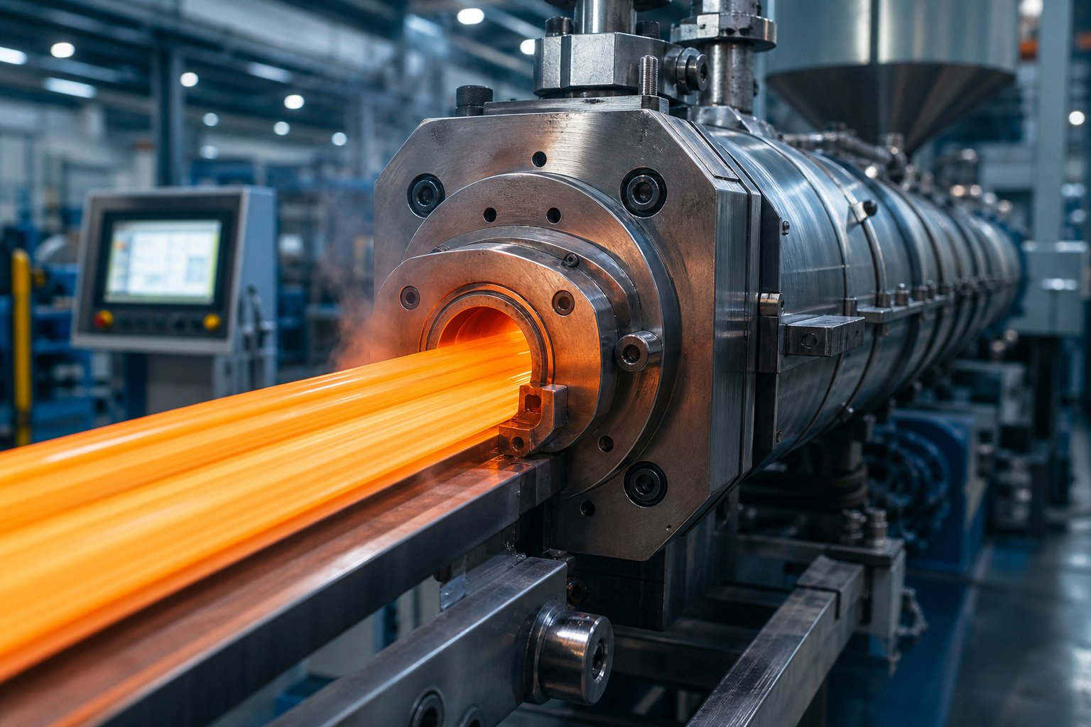
What Is Polymer Extrusion and Why It Matters
Imagine feeding a handful of tiny plastic pellets into one end of a machine and pulling out a perfectly shaped pipe, film, or gasket from the other. That continuous transformation — raw material in, finished profile out — is the heart of polymer extrusion. Yet the term itself is routinely confused with a narrower cousin, leaving engineers, buyers, and students with an incomplete picture of what this process truly covers.
Polymer extrusion is a continuous manufacturing process in which raw polymeric material is melted, homogenized, and forced through a shaped die to produce products with a consistent cross-section — encompassing thermoplastics, elastomers, thermosets, and biopolymers alike.
That definition matters more than it might seem at first glance. Most online resources treat "what is plastic extrusion" and polymer extrusion as interchangeable phrases. They are not. Understanding the distinction is the first step toward choosing the right materials, equipment, and process parameters for any extrusion operation.
Defining Polymer Extrusion Beyond Plastics
Plastic extrusion typically refers to the processing of thermoplastics — materials like polyethylene, polypropylene, and PVC that soften when heated and solidify upon cooling. These are certainly the highest-volume extrusion materials, but they represent only one branch of the polymer family tree.
Polymer extrusion is the broader umbrella. It includes:
- Thermoplastics — reversible melt processing; can be reshaped multiple times (PE, PP, PS, PVC, ABS, PC).
- Elastomers — flexible, rubber-like polymers extruded into seals, gaskets, and medical tubing. Thermoplastic elastomers (TPEs) combine rubber-like elasticity with the processability of plastics.
- Thermosets — polymers that undergo an irreversible chemical cure during or after extrusion, producing permanently hardened profiles with high thermal stability.
- Biopolymers — emerging materials like PLA and PHA derived from renewable feedstocks, processed through extrusion for sustainable packaging and disposable goods.
When someone asks "what is polymer extrusion," the accurate answer spans all four categories. Limiting the conversation to plastics alone ignores a significant share of extruded products — from silicone tubing in hospitals to biodegradable film on grocery shelves.
Why Polymers Can Be Extruded
So what is it about polymers that allows them to be continuously pushed through a die and emerge as a stable shape? The answer sits at the intersection of heat and molecular behavior — the core of extrusion science.
Every polymer has characteristic thermal transitions. Amorphous polymers (like polystyrene or polycarbonate) soften gradually above their glass transition temperature (Tg), the point where rigid molecular chains gain enough energy to begin sliding past one another. Semi-crystalline polymers (like polyethylene or nylon) must be heated past their melt temperature (Tm), where ordered crystalline regions break down and the material flows freely.
Between these thermal boundaries, polymers exhibit viscoelastic behavior — they act as both a viscous liquid and an elastic solid at the same time. Picture honey being stirred: it flows, but it also resists and springs back slightly. Polymer melts behave similarly, and that dual nature is what makes extrusion possible. Shear friction generated between the rotating screw and the barrel wall heats and drives the melt forward, while the elastic component — sometimes called rotational memory — causes the extrudate to "remember" its deformation, influencing phenomena like die swell after the material exits the die.
These viscoelastic properties are not a quirk to work around; they are the very reason a molten polymer can be shaped continuously under pressure and hold its form during cooling. Grasping this interplay between viscosity, elasticity, and thermal transitions is what separates routine processing from truly optimized extrusion — and it sets the stage for understanding every equipment choice and process parameter that follows.
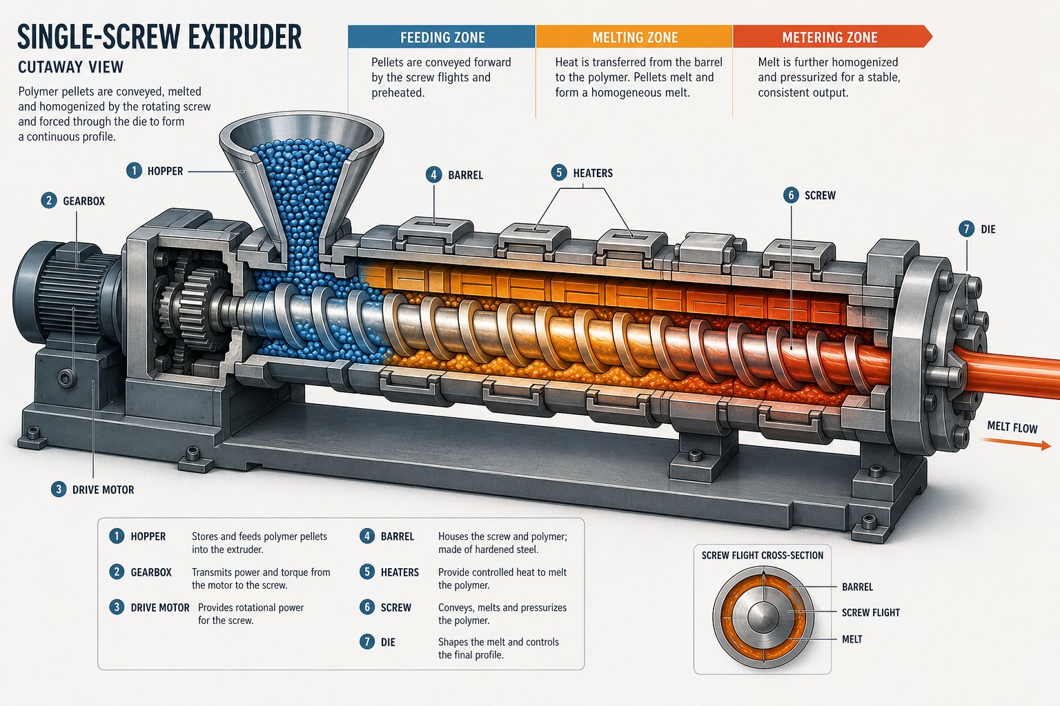
How the Polymer Extrusion Process Works Step by Step
Viscoelastic behavior and thermal transitions explain why polymers can be extruded — but knowing the science behind the melt is only half the picture. The real challenge for operators and engineers lies in controlling what happens at every stage inside the machine. Each phase of the polymer extrusion process introduces variables that directly affect product quality, dimensional accuracy, and throughput. Miss a critical parameter at one stage, and the defect shows up three stages later.
The following walkthrough breaks the extrusion process into its core stages, highlighting what to monitor and why it matters at each point along the barrel.
Feeding and Solid Conveying Stage
Everything starts at the hopper — a seemingly simple funnel that has more engineering behind it than most people realize. Pellets, granules, or powder enter the feed throat and are conveyed forward by the screw's root diameter in the feed zone. Two feeding strategies dominate the plastic extrusion process:
- Flood feeding — the hopper stays full, and gravity keeps a constant column of material above the screw. This is the standard approach for most single-screw operations running commodity polymers.
- Starve feeding — a metering feeder upstream controls exactly how much material enters the barrel per minute. This method is preferred for twin-screw compounding and when precise additive dosing is needed.
Consistent pellet flow is essential here. Bridging or funnel flow in the hopper creates air pockets and feed surges, which translate directly into pressure fluctuations downstream. You'll notice these as periodic thickness variations in the finished product.
Equally critical is moisture control. Hygroscopic polymers — nylon, polycarbonate, PET, and ABS among them — absorb atmospheric moisture that vaporizes during heating and causes bubbles, splay marks, and degraded mechanical properties. Pre-drying these resins in a desiccant dryer to manufacturer-specified levels is non-negotiable before material ever touches the feed throat.
Melting and Metering Through the Barrel
As the screw rotates — typically at speeds up to 120 RPM depending on the polymer and application — solid pellets are compressed, heated, and transformed into a homogeneous melt. Two energy sources drive this transformation: shear friction between the screw flights and barrel wall, and external barrel heaters arranged in multiple PID-controlled zones along the barrel length.
In many thermoplastic extrusion process setups, shear friction contributes the majority of the melt energy, especially at higher screw speeds. The barrel heaters fine-tune the temperature profile, with zones typically increasing gradually from the feed section to the metering section. Melt temperatures commonly range from 200 to 275°C, though the exact profile depends heavily on the polymer being processed.
Before the melt reaches the die, it passes through the breaker plate and screen pack. This assembly serves a dual purpose: it filters contaminants, gels, and unmelted particles from the melt stream, and it generates essential back pressure within the barrel. Back pressure improves melt homogeneity by forcing the polymer to mix more thoroughly. Pressures at the breaker plate can exceed 34 MPa in normal operation — a detail that underscores why screen pack condition and breaker plate integrity deserve regular inspection.
The metering zone, located at the screw's discharge end, is where uniformity is won or lost. A consistent metering zone output means steady volumetric flow to the die, which in turn means consistent wall thickness, weight-per-meter, and surface finish. Operators should monitor melt pressure and temperature at the screw tip closely. Fluctuations here ripple forward into every dimension of the finished part.
Die Forming and Downstream Processing
Molten polymer exits the metering zone, flows through an adapter, and enters the die — the precision-machined tool that defines the product's cross-sectional geometry. Inside the die, flow channels distribute the melt evenly and shape it into the desired profile. Whether it's a flat sheet, an annular tube, or a complex window frame profile, the die must deliver uniform velocity across the entire exit opening. Uneven flow creates thickness variations that no amount of downstream correction can fully resolve.
What happens immediately after the die depends on the product type. In the extrusion tube process, the extrudate passes through a vacuum sizing tank where negative pressure holds the soft tube against a calibration sleeve, locking in outside diameter and roundness. Films may be cooled by an air ring (in blown film) or chilled rolls (in cast film). Sheets and profiles typically travel through a water bath or spray cooling station before reaching haul-off units and cutters.
For quick reference, here are the sequential stages of extrusion processing from raw material to finished product:
- Material preparation — drying, blending, and additive dosing as required by the polymer.
- Feeding and solid conveying — controlled introduction of pellets into the barrel via hopper and feed throat.
- Melting and plasticizing — conversion of solid pellets to a homogeneous melt through shear and heat.
- Metering — steady-state delivery of uniform melt to the die at consistent pressure and temperature.
- Die forming — shaping the melt into the target cross-section as it exits the die.
- Cooling and sizing — solidifying the extrudate via water bath, air ring, calibration sleeve, or chill rolls.
- Haul-off, cutting, and finishing — pulling the cooled product at a controlled line speed, then cutting or winding to specification.
Throughout every stage, four critical process parameters demand constant attention: melt temperature (governs viscosity and degradation risk), screw speed (controls throughput and shear input), die pressure (reflects flow resistance and melt uniformity), and line speed (determines final dimensions and cooling time). A change in any one of these parameters cascades through the entire system.
With the process stages mapped out, the natural question becomes: what equipment actually makes all of this happen — and how do differences in screw geometry and extruder architecture shape the quality of the final product?
Extrusion Equipment and Screw Design Fundamentals
The screw is the heart of every plastic extruder. It melts, mixes, pressurizes, and delivers polymer to the die — and its geometry determines whether you get a flawless product or a reject pile. Yet screw design remains one of the least understood aspects of extrusion processing, even among experienced operators. So what are extruders, really, beyond the simplified diagrams in textbooks? They are precision-engineered systems where barrel architecture, screw geometry, and drive mechanics must work in concert with the polymer's rheology. Let's break down the key equipment decisions that shape output quality.
Single-Screw vs Twin-Screw Extruder Architecture
Choosing the right extruder for polymer processing starts with a fundamental architectural question: single screw or twin screw? Each platform excels in different scenarios, and selecting the wrong one creates problems no amount of parameter adjustment can fix.
A single-screw plastic extrusion machine uses one rotating screw inside a heated barrel. It relies primarily on drag flow — friction between the polymer and the barrel wall — to convey and pressurize the melt. This design is simpler, less expensive, and perfectly suited for high-volume production of finished profiles, pipes, sheets, and films where the polymer arrives pre-compounded and ready to process.
Twin-screw extruders, by contrast, use two intermeshing screws (co-rotating or counter-rotating) that provide positive displacement conveying and far superior distributive mixing. They excel at compounding — blending polymers with fillers, pigments, flame retardants, or reinforcing fibers — and at processing materials that are difficult to feed or require devolatilization.
| Extruder Type | Mixing Efficiency | Typical Applications | Best-Suited Polymers |
|---|---|---|---|
| Single-Screw | Moderate — relies on special mixing sections for homogeneity | Pipe, profile, film, sheet, and coating extrusion | PE, PP, PS, PVC, ABS, PC (pre-compounded) |
| Twin-Screw (Co-Rotating) | Excellent — high distributive and dispersive mixing | Compounding, masterbatch production, reactive extrusion, devolatilization | Engineering resins, filled systems, blends, recycled feedstock |
| Twin-Screw (Counter-Rotating) | Good — strong positive pumping with controlled shear | PVC pipe and profile extrusion, calender feeding | PVC (rigid and flexible), sensitive heat-degradable polymers |
You'll notice that a dedicated pvc extruder often uses counter-rotating twin-screw architecture. PVC's thermal sensitivity and tendency toward degradation make the controlled shear and positive conveying of this design ideal — it minimizes residence time while still achieving adequate fusion.
Screw Design Principles That Affect Output Quality
Whether you're running a single-screw or twin-screw platform, the screw's geometry dictates melt quality. Three design parameters matter most:
L/D Ratio (Length-to-Diameter Ratio)
The L/D ratio expresses how long the screw is relative to its diameter. According to extrusion engineering references, the most common L/D is around 24:1, with some designs stretching to 30:1 or longer for applications requiring extended melting, mixing, or devolatilization time. Shorter screws (20:1) suit materials that melt easily and need minimal mixing. A longer L/D gives the processor more flexibility — more barrel length for heat transfer, more residence time for thorough melting, and more room for specialized mixing sections.
Compression Ratio
The compression ratio describes how much the channel depth decreases from the feed zone to the metering zone — typically ranging between 2:1 and 4:1. This ratio must be matched to the polymer being processed. Polyolefins like PE and PP tolerate higher compression ratios (3:1 to 3.5:1) because they melt progressively and can absorb the resulting pressure buildup. PVC, however, demands low-compression screws (around 1.5:1 to 2:1) because excessive compression generates localized overheating that triggers degradation — another reason pvc extruder designs are so specialized.
Barrier and Mixing Designs
A standard three-zone screw — feed, compression, metering — works acceptably for many applications, but higher-performance operations use barrier screw designs. A barrier screw introduces a secondary flight in the compression zone that creates two parallel channels: one for unmelted solids and one for melt. As Allan Griff explains in his extrusion operating manual, the clearance between the barrier flight and barrel is large enough for melt to pass over but small enough to block pellets (roughly 1.5 mm). This separation forces pellets to generate more frictional heat against each other, dramatically improving melting efficiency per revolution.
For additional mixing downstream, Maddock sections (fluted mixing elements) strain the melt through a barrier ridge with tight clearance — typically 0.50 to 0.75 mm — ensuring thermal uniformity and catching any remaining unmelted particles. Mixing pins, arranged as rings of studs projecting from the screw root, disrupt laminar flow in the final quarter of the screw to boost color and additive dispersion.
Barrel and Screw Maintenance Considerations
Even the best-designed screw wears over time. The clearance between screw flights and the barrel wall starts at 0.125 to 0.25 mm on new plastic extruders, but abrasive fillers — glass fiber, calcium carbonate, talc, and recycled material with contaminants — accelerate wear on both surfaces. Wider clearance means more melt leakage over the flights, reduced pumping efficiency, higher energy consumption, and inconsistent output.
Watch for these warning signs of wear:
- Gradual output loss at the same screw speed, requiring higher RPM to maintain throughput.
- Increased melt temperature without changes to barrel heater setpoints — indicating the screw is working harder to compensate for lost efficiency.
- Greater product weight variation or dimensional inconsistency, especially in thin-wall products.
- Visible scoring or uneven wear patterns on screw flights when pulled for inspection.
Barrels wear too. They are typically steel cylinders lined with a wear-resistant alloy, and once that lining is compromised, replacement is the only reliable solution. The critical point often overlooked: replacement screw barrels must match original specifications — same metallurgy, same flight geometry, same clearances — or the carefully tuned relationship between screw and barrel breaks down. A new screw in a worn barrel, or a rebuilt barrel with an off-spec screw, introduces unpredictable flow behavior that no process setting can fully compensate for.
For extrusion manufacturers and recycling plants sourcing replacement components, working with a supplier that understands application-specific requirements is essential. NANHAIYA's plastic extruder machine and screw barrel support page offers custom screw design consultation and component guidance spanning pipe, profile, film, sheet, WPC, and granulation equipment — a practical resource when you need replacement screw barrels engineered to match your existing system's specifications rather than generic off-the-shelf parts.
Screw and barrel condition sets the ceiling for what any extrusion line can achieve. But hardware alone does not determine output quality — the polymer you feed into that hardware brings its own set of processing demands, thermal boundaries, and behavioral quirks that fundamentally shape every parameter decision.
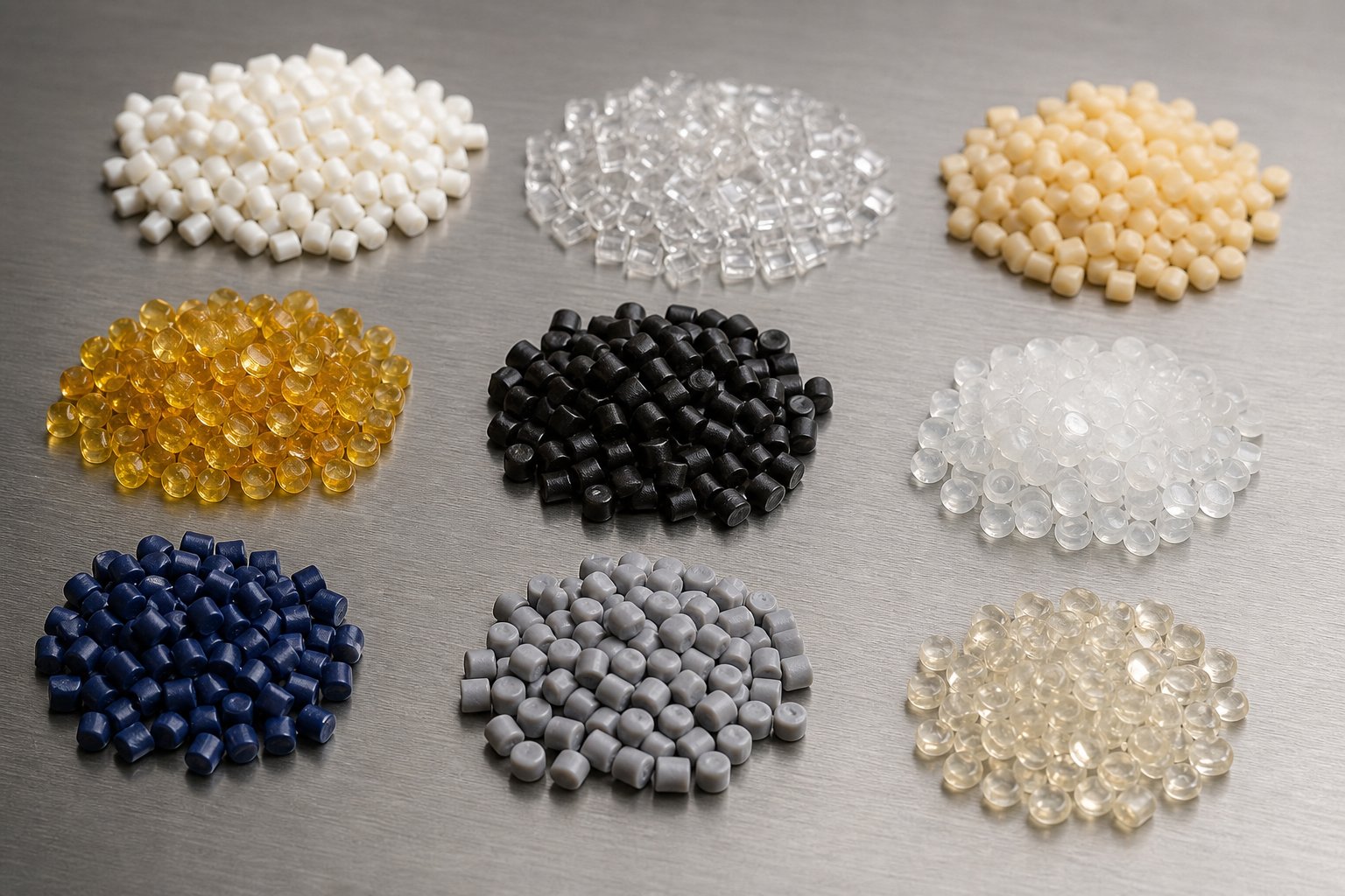
Polymer Materials and Their Extrusion Processing Characteristics
A perfectly designed screw running inside a pristine barrel still produces rejects if the polymer feeding into it is mishandled. Every resin brings a unique fingerprint of thermal transitions, flow behavior, and sensitivity to heat and moisture — and those properties dictate barrel temperatures, screw speed limits, and die geometry in ways that cannot be guessed. Understanding how plastic extrusion materials behave under processing conditions is what separates a stable, high-quality line from one that chases defects all shift long.
How Polymer Properties Shape Extrusion Parameters
Four material characteristics drive nearly every processing decision in thermoplastic extrusion: crystallinity, thermal sensitivity, melt flow index, and moisture absorption. Change any one of them, and the entire temperature-speed-pressure balance shifts.
Crystallinity
Semi-crystalline polymers — polyethylene, polypropylene, nylon — contain ordered molecular regions that absorb significant energy before melting. They exhibit a sharp melt transition: below the melt temperature, the material stays relatively rigid; above it, viscosity drops quickly. This means barrel temperature profiles for semi-crystalline resins must cross a well-defined threshold, and even a few degrees of undershoot can leave unmelted particles in the extrudate. In practice, extruded polyethylene demands precise zone temperatures because HDPE's melting point sits in a narrow band around 130-135°C, and the processing window above that point must balance flow with degradation risk.
Amorphous polymers — polystyrene, ABS, polycarbonate — lack crystalline structure entirely. They soften gradually above their glass transition temperature rather than melting sharply. This gives operators a wider working range but introduces its own challenge: without a clear melt point, it is easier to overheat amorphous materials without obvious visual feedback, leading to thermal degradation that only shows up as yellowing or reduced impact strength in the finished product.
Thermal Sensitivity
Some polymers tolerate heat well; others do not forgive even brief overexposure. PVC is the classic example — its decomposition temperature sits dangerously close to its processing temperature, meaning low to moderate screw speeds and carefully controlled barrel zones are mandatory. Polycarbonate extrusion presents a different kind of thermal challenge: PC processes at high temperatures (280-320°C) and requires thorough drying beforehand, but it tolerates those temperatures well as long as residence time stays reasonable.
Melt Flow Index (MFI)
MFI quantifies how easily a polymer flows under a standardized load and temperature. It serves as a quick screening tool for matching a resin to a process. Lower MFI values indicate higher molecular weight and greater melt viscosity — these grades resist flow, demand more screw torque, and build higher die pressures, but they deliver superior mechanical properties in the final part. Higher MFI polymers flow more readily, which suits thin-wall or high-speed applications but may sacrifice melt strength. As SpecialChem's MFI guide notes, two polymers with identical MFI values will not necessarily behave the same under real processing conditions because MFI is measured at a single shear rate and temperature — it does not capture the full picture of long-chain branching, shear-thinning behavior, or elastic recovery in the die.
Moisture Absorption
Hygroscopic resins — nylon, polycarbonate, ABS, PET — pull moisture from ambient air. Water molecules trapped inside pellets vaporize during melting, creating bubbles, surface splay, and hydrolytic chain scission that permanently weakens the polymer. Desiccant drying to specific moisture levels (often below 0.02% for PC, below 0.2% for nylon) is a mandatory pre-processing step, not an optional one. Non-hygroscopic polyolefins like PE and PP are far more forgiving, though surface moisture from outdoor pellet storage can still cause cosmetic defects.
Processing Profiles for Common Extrusion Polymers
When you're setting up a new line or switching materials, having a quick-reference comparison of extrusion materials saves time and prevents costly trial-and-error. The table below profiles six widely used extrusion grade polymers, drawing on published processing data for temperature ranges and known processing behaviors.
| Polymer | Processing Temp Range | Key Material Properties | Typical Extruded Products | Known Processing Challenges |
|---|---|---|---|---|
| PE (HDPE/LDPE) | 170-205°C | Semi-crystalline; low moisture absorption; medium viscosity (HDPE), low viscosity (LDPE) | Pipe, film, sheet, wire coating, geomembranes | Narrow melt point for HDPE; die swell management; oxidation at elevated temps |
| PP | 200-250°C | Semi-crystalline; high viscosity; good chemical resistance; moderate thermal stability | Sheet, thermoforming stock, fibers, profiles, strapping | High viscosity demands adequate torque; warping tendency during cooling; sensitive to oxidative degradation |
| PVC (Rigid) | 160-210°C | Amorphous; high viscosity; very low thermal stability; requires stabilizers | Pipe, window profiles, siding, conduit | Decomposition near processing temp; requires low-compression screws and short residence time |
| ABS | 200-250°C | Amorphous; moderate viscosity; hygroscopic; good impact strength | Profiles, sheet, edge banding, refrigerator liners | Must be dried to below 0.1% moisture; yellowing if overheated; moderate die swell |
| PS | 180-240°C | Amorphous; low viscosity; low thermal stability; brittle | Sheet for thermoforming, foam board, packaging | Low screw speeds recommended to limit shear heating; brittle extrudate requires careful handling |
| PC | 280-320°C | Amorphous; high processing temp; hygroscopic; excellent clarity and impact | Sheet, multi-wall panels, optical film, profiles | Requires thorough drying (below 0.02% moisture); high melt viscosity demands robust drive systems; stress-crack sensitivity |
Notice how the temperature ranges vary by more than 150°C across these six resins. Polypropylene extrusion, for example, runs a full 40-90°C hotter than rigid PVC — a gap that affects screw metallurgy, seal design, and even the type of barrel heaters used. Polycarbonate extrusion pushes temperatures higher still, demanding equipment rated for sustained operation above 300°C and drying systems capable of achieving ultra-low residual moisture.
Extrusion-Grade Polymer Selection Criteria
Not every grade of a given polymer is suitable for extrusion. Walk into a resin supplier's catalog and you'll find dozens of polyethylene grades — some designed for injection molding, some for blow molding, and only a subset optimized for extrusion. What separates them?
Three characteristics define a true extrusion grade polymer:
- Higher melt strength — Extrusion-grade resins maintain their structural integrity as a molten strand exits the die and spans the air gap before cooling. Injection-molding grades, optimized for rapid cavity fill, often flow too freely and sag or distort during this unsupported phase.
- Broader processing window — The gap between the minimum temperature for adequate flow and the maximum temperature before degradation is wider in extrusion grades. This gives operators more room to fine-tune parameters without drifting into defect territory.
- Specific MFI ranges — Extrusion grades typically sit at the lower end of the MFI spectrum for their polymer family, reflecting higher molecular weight and greater viscosity. For polypropylene, extrusion grades commonly fall in the 0.3-4 g/10 min range, while injection-molding grades may exceed 10-30 g/10 min. Research on MFI relationships confirms that lower MFI polymers deliver better environmental stress-crack resistance, impact performance, and barrier properties — all critical for extruded products that must survive long-term service.
Specialty grades push these principles further. Polyethylene resins designed for film extrusion feature long-chain branching that increases melt strength and promotes stable bubble formation in blown film operations. Polypropylene grades formulated for sheet applications balance stiffness with enough melt elasticity to avoid sag on wide flat dies. Selecting the wrong grade — even within the same polymer family — creates processing headaches that no amount of screw speed or temperature adjustment can resolve.
Matching polymer properties to equipment capability is one side of the equation. The other side is matching both to the right extrusion process type — because a pipe die, a blown-film tower, and a profile line each impose their own demands on how that polymer must perform.
Types of Polymer Extrusion Processes Explained
A resin perfectly matched to screw geometry and barrel temperature still produces the wrong product if it exits the wrong kind of die. Each extrusion process type — pipe, film, sheet, profile, or co-extrusion — imposes distinct demands on die design, downstream cooling, and dimensional control. Choosing the right one starts with understanding what each process does, how it differs from the others, and where each one excels.
Pipe and Tube Extrusion
Plastic pipe extrusion uses an annular die — a circular opening with a central mandrel (pin) that creates a hollow cross-section. Molten polymer flows around the mandrel, exits as a soft tube, and immediately enters a vacuum sizing tank. Inside that tank, carefully controlled negative pressure draws the still-pliable pipe outward against a calibration sleeve, locking in the target outside diameter and roundness. Without vacuum sizing, the soft extrudate would sag or deform under its own weight before solidifying.
According to process engineering references, a typical pipe extrusion line includes five main stations: die and tooling, sizing and calibration, cooling tanks, haul-off puller, and cutting or coiling equipment. The variables that most affect dimensional quality in extrusion of pipes are the balance between melt output and puller draw speed, vacuum stability in the sizing station, and uniform cooling along the tank length. Even small fluctuations in any of these parameters show up as OD drift, wall variation, or ovality in the finished pipe.
PVC, PE, and PP dominate plastic tube extrusion applications. PVC's rigidity makes it the standard for pressure pipe and conduit, while HDPE's flexibility and chemical resistance suit water distribution and gas piping. PP finds its niche in high-temperature drainage and chemical-handling systems.
Film and Sheet Extrusion
Film and sheet may look like variations of the same thing — flat plastic — but they differ in thickness, equipment, and end use. The dividing line sits at roughly 0.25 mm: anything thinner is generally classified as film, anything thicker as sheet.
Blown film extrusion pushes melt through an annular die, then inflates the emerging tube with internal air pressure to form a thin bubble. An air ring cools the outside of the bubble, and as the film solidifies at the frost line, collapsing frames and nip rollers flatten it into lay-flat tubing for winding or slitting. The blow-up ratio — the ratio of bubble diameter to die diameter — controls both film thickness and molecular orientation. A higher ratio stretches molecules more in the transverse direction, improving tear resistance across the width. Polymer film extrusion through this method demands tight gauge control, because even slight variations in air pressure or cooling uniformity create thickness bands that ripple through downstream converting operations.
Cast film extrusion uses a flat die (T-die or coat hanger die) and deposits the melt directly onto a polished chill roll. Rapid quenching produces excellent optical clarity and tighter thickness tolerance compared to blown film, making cast film ideal for stretch wrap and barrier packaging. The tradeoff is less biaxial orientation, which means lower tear strength in the transverse direction.
Plastic sheet extrusion follows a similar flat-die approach but operates at greater thicknesses, using a series of polished calendering rolls that simultaneously cool the sheet, set its final thickness, and determine surface texture. Common sheet extrusion materials include PP, PET, PS, ABS, and PC. A frequent post-processing step is thermoforming, where the flat sheet is reheated and vacuum-formed into three-dimensional shapes like clamshell packaging, refrigerator liners, and automotive interior panels.
Profile Extrusion and Co-Extrusion
Not every product has a simple round or flat cross-section. Plastic profile extrusion produces complex, custom shapes — window frames, door seals, gaskets, cable channels, edge trim, and decorative moldings — by forcing molten polymer through intricately machined dies. The die design challenge is significant: melt must flow evenly through sections of wildly different thickness and geometry, or the finished profile warps, bows, or develops internal stresses that emerge during cooling.
Profile dies typically require careful balancing of flow channels and land lengths to equalize velocity across every section of the exit opening. After leaving the die, the soft profile enters a calibration fixture — often water-cooled and vacuum-assisted — that holds the shape until the polymer rigidifies. PVC dominates window and siding profile extrusion because of its excellent weatherability, flame resistance, and relatively low cost.
Plastic coextrusion takes profile, pipe, film, and sheet production a step further by combining multiple polymer layers in a single pass. Two or more extruders feed different materials into a shared die head, where the melts merge into a multi-layer structure. Each layer brings a specific function — for example, a structural core for strength, a cap layer for UV protection, and a barrier layer for oxygen resistance.
The key engineering challenge in co-extrusion is material compatibility. When adjacent layers have different chemistries — say polyethylene next to nylon — they will not bond without a tie layer, a thin adhesive resin positioned between them. Co-extrusion technology references note that layer thicknesses are controlled by the relative speeds and sizes of the individual extruders delivering material to the die. Five-layer and even seven-layer structures are increasingly common in food packaging, where oxygen barrier performance, moisture resistance, and mechanical strength must coexist in a single film or sheet.
Co-extrusion also finds heavy use in automotive trim, medical tubing with layered durometers, and construction profiles where a recycled-content core is capped with a virgin-polymer skin for appearance and performance.
Choosing the Right Extrusion Type
With several process variants available, matching product requirements to the right extrusion method avoids expensive tooling mistakes and material waste. Use this decision framework to narrow your options:
- Constant hollow cross-section (round or near-round) — Start with pipe or tube extrusion. Select annular die tooling sized for your OD and wall targets, and match the polymer to the end-use environment (pressure rating, chemical exposure, temperature).
- Thin, flexible product under 0.25 mm — Evaluate blown film extrusion for balanced biaxial properties (bags, agricultural film) or cast film extrusion for superior clarity and gauge uniformity (stretch wrap, barrier packaging).
- Flat, rigid product over 0.25 mm — Sheet extrusion with flat-die and chill roll systems is the standard. Consider thermoformability requirements when selecting both resin grade and sheet thickness.
- Complex, non-circular cross-section — Profile extrusion with a custom-machined die handles window frames, gaskets, trim, channels, and any geometry with a constant cross-section along its length.
- Multi-functional performance in a single product — Co-extrusion enables layered structures that combine barrier, structural, aesthetic, and adhesive properties. Factor in tie-layer requirements and confirm material compatibility before tooling design.
- High-volume continuous output with minimal waste — All extrusion types excel here compared to discrete-part processes, but film and pipe lines typically achieve the highest throughputs per hour of operation.
Each of these process types produces consistent, repeatable output — when everything is running right. The real test comes when surface roughness appears on a pipe, gauge bands develop across a film, or a profile starts warping off the calibrator. Knowing how to diagnose and correct those defects quickly is what keeps a line profitable rather than frustrating.
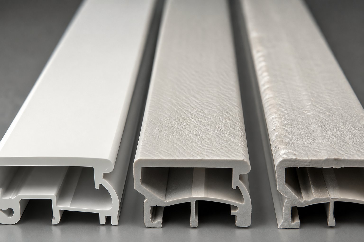
Common Extrusion Defects and How to Troubleshoot Them
A perfectly configured extrusion system still encounters defects. Surface flaws, dimensional drift, and internal voids appear even on well-maintained lines — and every one of them traces back to a specific imbalance in temperature, pressure, material condition, or equipment wear. The difference between a minor hiccup and hours of scrap comes down to how quickly you identify the root cause. This section gives engineers and operators a practical diagnostic framework for the defects most commonly found in extruded plastics.
Surface Defects and Their Root Causes
Melt fracture shows up as wavy, spiraling distortions across the surface of extruded plastic parts. It occurs when shear stress inside the die exceeds the polymer's critical threshold, disrupting smooth laminar flow into chaotic, turbulent movement. Reducing extrusion speed, increasing melt temperature to lower viscosity, or widening the die land to reduce shear rate at the exit all help restore stable flow.
Shark skin is subtler — fine, regularly spaced ridges running along the extrusion direction. This defect originates at the die exit, where the outer surface of the melt accelerates and stretches as it leaves the constraining die wall. The rapid transition from no-slip contact to free surface creates localized tensile stress that tears the skin on a microscopic level. Raising die lip temperature or applying a processing aid that reduces surface friction at the die exit are the most effective corrections.
A rough surface without a clear repeating pattern usually points to contamination in the melt stream, degraded polymer particles, or an inadequately cleaned die face. When extruding plastic with recycled content, this type of roughness is especially common and often requires finer screen packs and tighter incoming material quality checks.
Dimensional and Structural Defects
Die swell — the extrudate expanding beyond the die's dimensions — is a direct consequence of the polymer's elastic memory. Molecular chains compressed and sheared inside the barrel partially spring back to their relaxed state once the constraining die wall disappears. The result is an extrudate that's measurably larger than the die opening. Die swell is predictable and manageable through die design (longer land lengths allow stress relaxation before exit) and by adjusting melt temperature, since higher temperatures reduce stored elastic energy.
Uneven wall thickness in pipe and profile plastic extrusions typically signals die misalignment, unbalanced flow channels, or inconsistent cooling. As extrusion engineering resources note, repeating thick-thin patterns point to die-side causes, while random thickness drift suggests upstream issues like feed instability or melt temperature variation across the barrel.
Voids — internal bubbles or hollow pockets — stem from two primary sources: moisture vaporizing inside the melt (especially in hygroscopic resins processed without adequate drying) or thermal degradation generating gas. Either way, the fix starts with verifying drying conditions and reviewing the barrel temperature profile for hot spots that cause localized overheating.
Warping occurs when the extrudate cools unevenly, locking in internal stresses that release as distortion once the part is cut or stored. Symmetric cooling — balanced water spray, uniform air flow, properly aligned calibration fixtures — is the primary defense. Material selection also plays a role, since semi-crystalline polymers with high shrinkage rates are more prone to warping than amorphous alternatives.
Systematic Troubleshooting Approach
Rather than chasing individual symptoms, experienced operators classify the defect first, then work through a structured diagnostic path. The table below organizes the most common defects into a quick-reference format — matching what you see on the line with probable causes and the corrective actions most likely to resolve the issue.
| Defect Type | Likely Causes | Corrective Actions |
|---|---|---|
| Melt fracture (wavy, distorted surface) | Excessive shear stress at die; melt temperature too low; die land too short | Reduce screw speed; raise melt temperature; lengthen die land; consider processing aids |
| Shark skin (fine surface ridges) | Die exit instability; high surface shear at die lip | Increase die lip temperature; apply fluoropolymer processing aid; reduce output rate |
| Rough or streaked surface | Contamination; degraded material; dirty die face | Inspect and replace screen pack; clean die surfaces; verify resin quality |
| Die swell (oversized extrudate) | High elastic recovery; short die land; low melt temperature | Lengthen die land; increase melt temperature; reduce screw speed to lower shear history |
| Uneven wall thickness | Die misalignment; unbalanced flow channels; melt temperature variation; inconsistent cooling | Re-center die to screw axis; balance die flow restrictors; verify barrel zone temperatures; align cooling tank |
| Voids and bubbles | Moisture in hygroscopic resin; thermal degradation; insufficient venting | Dry resin to manufacturer specs; lower barrel temperatures at hot spots; check vent port for blockage |
| Warping and bowing | Uneven cooling; high internal stress; asymmetric profile geometry | Balance cooling on all sides; reduce line speed to extend cooling time; verify calibration fixture alignment |
| Yellowing or burn marks | Excessive residence time; hot spots in barrel; polymer degradation | Reduce barrel temperature at affected zone; increase throughput to shorten residence time; purge degraded material |
One critical distinction separates routine troubleshooting from deeper investigation: does the defect point to a process parameter problem or an equipment problem? If adjusting melt temperature, screw speed, or cooling resolves the issue, the root cause was a parameter mismatch. But if the same defect returns despite correct settings — or gradually worsens over weeks — the extrusion system itself likely needs attention. Worn screw flights reduce pumping efficiency and create temperature inconsistencies that mimic process errors. Damaged or scored die surfaces introduce surface defects that no temperature adjustment can eliminate. Misaligned downstream equipment causes dimensional problems that look like die issues but originate meters down the line.
The discipline is simple: classify the defect, check parameters first, and escalate to equipment inspection only when parameter corrections fail to hold. This structured approach prevents the most common troubleshooting mistake — changing multiple variables at once and losing track of what actually fixed (or worsened) the problem.
Defect diagnosis tells you how to keep your line running. But a broader question often precedes it: should you be running an extrusion line at all for a given product, or would injection molding, blow molding, or thermoforming serve the application better?
Polymer Extrusion vs Other Processing Methods
Imagine you have a product concept, a material shortlist, and a production target — but you're still not sure whether extrusion is the right extrusion manufacturing process for the job. It's a common crossroads. Polymer extrusion shares raw materials, machinery principles, and even some tooling concepts with injection molding, blow molding, thermoforming, and rotational molding. Yet each method occupies a distinct sweet spot defined by product geometry, volume requirements, tooling investment, and material efficiency. Picking the wrong process doesn't just waste money on tooling — it locks you into limitations that no amount of optimization can overcome.
Extrusion Compared to Injection Molding and Blow Molding
So what is polymer processing, really, if not the art of matching a shaping method to a product's geometry and performance demands? The table below lays out the five most common plastic processing methods side by side, comparing the factors that matter most when you're deciding how to manufacture a part.
| Process | Product Geometry Suitability | Production Volume Efficiency | Material Waste | Tooling Cost | Typical Products |
|---|---|---|---|---|---|
| Extrusion | Continuous profiles with a constant cross-section (pipes, sheets, films, channels, trim) | Excellent for high-volume continuous output | Very low — near-net-shape process with regrind reuse | Low to moderate (die tooling is simpler than mold tooling) | Pipe, tubing, window profiles, film, sheet, wire coating, gaskets |
| Injection Molding | Complex 3D parts with intricate features, variable wall thickness, and tight tolerances | Excellent for high-volume discrete parts; fast cycle times | Low to moderate — runners and sprues generate scrap unless hot runners are used | High (hardened steel molds for production; aluminum for prototyping) | Housings, connectors, gears, medical devices, consumer electronics enclosures |
| Blow Molding | Hollow parts — bottles, tanks, containers, ducts | High for standard containers; moderate for custom shapes | Moderate — flash and trim waste from parison pinch-off | Moderate (simpler molds than injection molding but more complex than extrusion dies) | Bottles, fuel tanks, drums, HVAC ducts, playground equipment |
| Thermoforming | One-sided 3D shapes formed from flat sheet — trays, covers, enclosures, panels | Good for medium to high volumes; slower cycle than injection molding | Moderate to high — trimmed skeleton sheet must be recycled | Low to moderate (molds are typically aluminum or composite, not hardened steel) | Packaging trays, vehicle interior panels, refrigerator liners, signage |
| Rotational Molding | Large, seamless hollow parts with uniform wall thickness | Low — slow cycle times; typically one part per mold per cycle | Very low — exact powder charge; minimal scrap | Low (cast aluminum or fabricated steel molds) | Water tanks, kayaks, playground equipment, large containers |
Several patterns stand out immediately. Extrusion molding dominates when the product has a uniform cross-section along its length — think pipes running dozens of meters, rolls of packaging film, or window profiles cut to size on site. Injection molding, by contrast, excels at discrete three-dimensional parts where features like ribs, bosses, snap fits, and complex internal geometries are molded directly into the component. Blow molding fills the gap for hollow containers that neither extrusion nor injection molding can produce efficiently. Thermoforming offers a cost-effective path to large, one-sided shapes when injection mold tooling would be prohibitively expensive. And rotational molding handles oversized seamless hollow parts — tanks, kayaks, playground structures — where other methods simply cannot scale up.
Material waste tells an equally important story. Extrusion moulding generates very little scrap because the process is continuous and near-net-shape; startup purge and trim can be reground and fed back into the line. Injection molding produces runner and sprue waste on cold-runner systems, though hot-runner molds eliminate most of it. Thermoforming's skeleton waste — the sheet material trimmed away around the formed part — can represent 30-50% of the starting sheet weight, making regrind recovery essential for cost control.
When to Choose Extrusion Over Alternative Processes
If you're evaluating multiple manufacturing routes for a new product, these decision criteria help determine whether extrusion is the right fit:
- The product has a constant cross-section along its length. Pipes, tubing, profiles, channels, seals, sheets, and films all qualify. If your part looks the same at every point along its length, extrusion is almost certainly the most efficient process.
- Production volumes are high and output must be continuous. Extrusion lines run continuously for hours or days at a time, producing hundreds or thousands of meters per hour. This throughput model suits commodity products and high-demand industrial components far better than batch processes like rotational molding or low-volume thermoforming.
- Material efficiency matters to your cost model. With near-zero scrap in steady-state operation and the ability to reprocess startup waste, extrusion delivers more finished product per kilogram of raw material than most alternatives.
- Tooling budget is constrained. Extrusion dies — even complex profile dies — cost a fraction of injection molds designed for equivalent production volumes. If your geometry fits the process, the capital savings are substantial.
- Multi-layer performance is needed in a single product. Co-extrusion enables barrier films, capped profiles, and layered sheets that would require secondary bonding or lamination steps in other processes.
- The product must be supplied in continuous lengths, rolls, or coils. No other polymer process delivers product in this format as naturally as extrusion.
Hybrid processes blur the boundaries in useful ways. Extrusion blow molding, for instance, starts with an extruded parison — a tube of molten polymer — which is then captured in a mold and inflated with air to form a hollow container. It combines extrusion's continuous material preparation with blow molding's ability to create hollow shapes, making it the standard method for producing bottles, containers, and automotive fuel tanks. As industry references note, extrusion blow molding handles both large and small hollow parts with faster cycle times than rotational molding, though it generates more flash waste than injection blow molding.
The right choice ultimately depends on geometry, volume, budget, and performance requirements working together — not any single factor in isolation. When the product fits extrusion's strengths, few processes can match its combination of throughput, efficiency, and cost per meter. When it doesn't, forcing the fit leads to compromises that injection molding, blow molding, or thermoforming would have avoided from the start.
Choosing the right process is a forward-looking decision. But increasingly, that decision also needs to account for what happens at the end of a product's life — how the material is reclaimed, reprocessed, and reintroduced into the extrusion line as recycled feedstock.
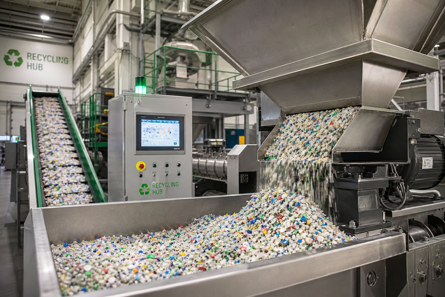
Sustainability and Recycling in Polymer Extrusion
Reclaiming plastic at the end of its useful life sounds straightforward in principle — grind it up, melt it again, and push it through a die. In practice, recycled feedstock introduces a cascade of processing variables that virgin resin simply does not. Contamination, inconsistent viscosity, and degraded mechanical properties turn what should be a circular solution into an engineering challenge that demands deliberate adjustments to equipment, process parameters, and quality expectations. The extrusion of polymers from post-consumer and post-industrial waste streams is growing rapidly, but doing it well requires understanding exactly where the difficulties lie.
Processing Regrind and Post-Consumer Resin
Regrind from in-house trim and startup scrap is the easiest recycled material to process — it comes from a known source with a known thermal history. Post-consumer resin (PCR), on the other hand, arrives with baggage: mixed colors, residual labels and adhesives, variable molecular weight from prior heat exposure, and inorganic contaminants that accelerate equipment wear.
These inconsistencies show up on the extrusion line in several ways:
- Fluctuating melt viscosity — Recycled flakes and pellets vary in molecular weight from batch to batch. One load flows easily; the next demands significantly more screw torque. This inconsistency creates pressure swings at the die that translate directly into dimensional variation in the finished product.
- Contamination and gels — Foreign materials, partially crosslinked particles, and degraded polymer fragments survive sorting and washing. They appear as specks, streaks, or hard spots in extruded polymers. Finer screen packs catch more of this debris, but they also increase back pressure and require more frequent changes — a tradeoff that affects line uptime.
- Reduced mechanical properties — Every time a polymer is melted, sheared, and cooled, its molecular chains shorten slightly. PCR has already been through at least one full cycle, and often more. The result is lower impact strength, reduced elongation, and diminished melt strength compared to the same polymer in virgin form.
Blending ratios offer a practical lever. Mixing 20-30% recycled content with virgin resin often produces output that meets original product specifications with minimal parameter adjustment. Push that ratio above 50%, and you'll typically need to recalibrate barrel temperatures, reduce screw speeds to limit additional shear degradation, and tighten quality inspection protocols. As Reifenhauser's recycling analysis notes, high recyclate content changes production conditions significantly — and the right technology can make producers more independent of input quality variation in the recyclate they process.
Equipment wear accelerates noticeably with recycled feedstock. Organic and inorganic impurities embedded in post-consumer material act as abrasives inside the barrel, grinding down screw flights and barrel linings faster than virgin resin ever would. Twin-screw extruders, with their superior mixing and devolatilization capability, are increasingly favored for recycling applications — they homogenize inconsistent feedstock more effectively and can incorporate degassing zones that remove trapped volatiles before the melt reaches the die. Even high-quality recyclates soil dies, cooling rings, and other plastic extrusion line components faster than virgin material, shortening cleaning intervals and increasing maintenance demands.
Recycling-grade extrusion demands different equipment considerations than virgin material processing — higher wear resistance in screws and barrels, more aggressive melt filtration, and process flexibility to accommodate feedstock that changes from load to load.
Biodegradable Polymers and Circular Economy Considerations
Beyond recycling conventional plastics, the extrusion of polymers from renewable feedstocks is gaining traction as brands and regulators push toward reduced fossil-resource dependence. Two biopolymers lead the field: polylactic acid (PLA) and polyhydroxyalkanoates (PHA). Both can be processed on standard extrusion equipment — but neither behaves like the polyolefins or styrenics that most lines are set up for.
PLA offers high rigidity and optical clarity similar to polystyrene, with a tensile strength of 50-70 MPa and a glass transition temperature of just 55-60°C. Its melt temperature ranges from 150 to 180°C — substantially lower than most conventional extrusion polymers. That narrow processing window means barrel temperature profiles must be tightly controlled. Overshoot by even a small margin and degradation begins; undershoot and you get incomplete melting and poor surface quality. PLA is also highly moisture-sensitive; without thorough drying to below 250 ppm moisture content, hydrolytic chain scission during processing destroys molecular weight and leaves the finished product brittle and hazy.
PHA is more forgiving in terms of flexibility — some copolymer grades offer elongation at break values ranging from 5% to as high as 500%, resembling polyethylene rather than polystyrene. Its thermal stability, however, is lower still, and processing temperatures must stay within a tight band to avoid decomposition. PHA's advantage lies in its genuine biodegradability across a wider range of environments, including marine conditions, which PLA cannot match.
Both biopolymers demand polymer extrusion technologies adapted to their sensitivities: lower barrel temperatures, gentler screw compression ratios, careful residence-time management, and drying systems calibrated for bio-based moisture uptake patterns. Operators accustomed to the broad processing windows of PE or PP will find the margin for error significantly smaller.
Where extrusion truly supports circular economy goals is in pelletizing and granulation. Reclaimed plastic — whether post-consumer waste, post-industrial trim, or end-of-life products — must be converted back into a uniform, feedable form before it can re-enter any manufacturing process. Extrusion-based granulation lines melt, filter, degas, and strand-cut or underwater-pelletize reclaimed material into consistent pellets ready for reuse. Industry experts at KraussMaffei report achieving throughput rates up to 6,000 pounds per hour on single-screw recycling extruders, with twin-screw configurations scaling even higher for applications requiring over 15% total recycled content. Their vision — 100% circularity where every piece of plastic is recycled, either mechanically or chemically — depends on extrusion line scalability and the continued development of filtration, degassing, and wear-resistant component technologies.
Sustainability in extrusion is not a future aspiration — it is a present-day operational reality that touches material selection, equipment specification, and process control. Whether you're blending 20% regrind into a pipe line or commissioning a dedicated PLA film extrusion line, the equipment and process knowledge required goes well beyond standard virgin-material playbooks. That practical reality — matching the right components, the right polymer grades, and the right process parameters to your specific operation — is exactly where the final steps of any extrusion project come into focus.
Practical Next Steps for Your Extrusion Operation
Knowledge without action stays theoretical. Everything covered in this article — from viscoelastic behavior and screw geometry to defect diagnosis and recycled feedstock challenges — converges on a single practical question: what should you actually do next to improve, specify, or upgrade your extrusion operation? Whether you're commissioning a new line for plastic extrusion products or squeezing better performance from aging plastic extrusion equipment, the path forward follows a logical sequence of decisions that build on each other.
Matching Your Product Requirements to Equipment and Materials
Think of every extrusion project as a triangle with three sides: process type, polymer grade, and screw-barrel configuration. Change one side, and the other two must adjust. A pipe line running HDPE needs an entirely different setup than a profile line extruding rigid PVC, even though both fall under the same extrusion technologies umbrella. Overlooking these interdependencies is the single most common reason new lines underperform or existing lines plateau.
Here is a structured checklist of actionable steps to take when specifying a new extrusion line or upgrading plastic extrusion machinery you already operate:
- Define product geometry and dimensional tolerances first. Pipe, film, sheet, or profile? Round, flat, or complex cross-section? Every downstream decision — die type, cooling method, haul-off configuration — flows from this starting point.
- Select the polymer grade based on end-use performance, not just price. Confirm that your resin is an extrusion grade with appropriate melt strength and MFI range. Verify drying requirements for hygroscopic materials and establish incoming moisture testing protocols.
- Match screw design to your specific polymer. Compression ratio, L/D ratio, and barrier or mixing element selection must align with the resin's melt behavior. A screw optimized for polyolefins will degrade PVC; a general-purpose design may underperform on engineering resins.
- Specify barrel and screw metallurgy for your feedstock. If you're processing filled compounds, recycled material with contaminants, or abrasive additives, standard nitrided barrels and chrome-plated screws may wear prematurely. Bimetallic barrels and tool-steel flights extend service life significantly.
- Map your temperature profile to the polymer's processing window. Use the material-specific temperature ranges discussed earlier as starting points, then fine-tune based on actual melt temperature readings at the screw tip and die adapter.
- Evaluate downstream equipment as part of the system, not an afterthought. Vacuum sizing tanks, cooling baths, haul-off pullers, and cutters must be sized and synchronized to the extruder's output rate. A mismatch anywhere downstream limits the entire line's capability.
- Build a preventive maintenance schedule from day one. Track screw and barrel wear measurements at regular intervals. Establish replacement thresholds before dimensional drift in your product signals that you've waited too long.
- Document your baseline process parameters. Record melt temperature, screw speed, die pressure, line speed, and output weight per meter during stable production. These baseline numbers become your diagnostic reference when defects appear later.
Each step reduces guesswork and narrows the gap between what your plastic extrusion machines are capable of and what they actually deliver shift after shift. Extrusion technologies continue to evolve — smarter drives, tighter temperature controls, more sophisticated co-extrusion die designs — but the fundamentals of matching product, polymer, and hardware remain constant.
Where to Find Reliable Extrusion Components and Support
Even the best-maintained screw eventually wears past its performance threshold. Barrel linings erode. Die components fatigue. When that moment arrives, the quality of your replacement parts determines whether your line returns to baseline performance or settles into a permanently compromised state.
Sourcing replacement screw barrels, die components, and wear parts is not a generic purchasing exercise. The replacement must match the original's metallurgy, flight geometry, and dimensional tolerances — or the carefully calibrated relationship between screw and barrel breaks down in ways that no process parameter adjustment can fully correct. As the extrusion line quotation analysis from industry sources emphasizes, even components that appear identical on paper can differ significantly in specification depth, and those differences show up directly in output consistency and equipment longevity.
Equally important is working with a supplier who understands your specific application. A screw designed for blown film extrusion faces different demands than one built for WPC decking or PVC pipe. Generic replacement parts treat all applications the same; application-specific suppliers do not. For extrusion manufacturers, recycling plants, and plastic processing teams seeking this level of targeted support, NANHAIYA's plastic extruder machine and screw barrel resource page offers custom screw design consultation and component guidance covering pipe, profile, film, sheet, WPC, and granulation equipment — a practical starting point when you need replacement components engineered for your exact production requirements rather than off-the-shelf approximations.
The right supplier relationship extends beyond parts fulfillment. Look for partners who can advise on screw geometry modifications when you change materials, recommend wear-resistant upgrades when your feedstock shifts toward higher recycled content, and provide dimensional inspection data for every replacement barrel shipped. That kind of plastic extrusion solutions support transforms component sourcing from a reactive cost center into a proactive performance investment.
Polymer extrusion — from the first pellet dropping into the hopper to the last meter of finished product rolling off the line — rewards those who treat it as an integrated system rather than a collection of independent variables. Master the connections between material science, screw design, process control, and maintenance discipline, and you'll find that consistent, high-quality output is less about chasing problems and more about preventing them from ever reaching the die.
Polymer Extrusion: Frequently Asked Questions
1. What is the difference between polymer extrusion and plastic extrusion?
Polymer extrusion is the broader umbrella term encompassing the continuous melt-processing of thermoplastics, elastomers, thermosets, and biopolymers through a shaped die. Plastic extrusion refers specifically to thermoplastics like PE, PP, and PVC. The distinction matters because elastomer seals, thermoset profiles, and biodegradable PLA films all require extrusion but fall outside the narrower 'plastic' category. Understanding this scope helps engineers select appropriate equipment and process parameters for the full range of extrudable materials.
2. How do I choose between a single-screw and twin-screw extruder?
Single-screw extruders suit high-volume production of pre-compounded polymers into finished products like pipes, films, sheets, and profiles. They are simpler and more cost-effective for straightforward melting and shaping tasks. Twin-screw extruders excel at compounding, blending polymers with additives, processing recycled feedstock, and handling materials requiring devolatilization or intensive mixing. Counter-rotating twin-screw designs are specifically preferred for thermally sensitive PVC processing. Your choice depends on whether the primary task is shaping a ready-to-use resin or mixing and modifying materials during the extrusion process. For application-specific guidance on screw barrel configurations, suppliers like NANHAIYA (nhyscrews.com) offer custom consultation for pipe, profile, film, sheet, WPC, and granulation setups.
3. What are the most common polymer extrusion defects and how are they fixed?
The most frequent extrusion defects include melt fracture (wavy surface caused by excessive die shear stress), shark skin (fine ridges from die-exit instabilities), die swell (oversized extrudate from elastic memory), uneven wall thickness, internal voids, and warping. Fixes vary by root cause: melt fracture responds to lower screw speeds or higher melt temperatures; shark skin improves with die lip heating or fluoropolymer processing aids; voids require proper resin drying; and warping demands balanced cooling on all sides of the extrudate. The key diagnostic discipline is distinguishing process parameter problems from equipment wear issues like worn screw flights or damaged die surfaces.
4. What makes a polymer 'extrusion grade' versus injection-molding grade?
Extrusion-grade polymers are formulated with higher melt strength to maintain structural integrity as the molten strand exits the die unsupported. They also feature broader processing temperature windows and lower melt flow index (MFI) values compared to injection-molding grades of the same polymer family. For example, extrusion-grade polypropylene typically has an MFI of 0.3-4 g/10 min, while injection-molding PP may exceed 10-30 g/10 min. These properties ensure the extrudate holds its shape during the air gap between die exit and cooling, preventing sag or distortion that would occur with higher-flow injection grades.
5. Can recycled plastics be processed through polymer extrusion successfully?
Yes, but recycled feedstock introduces challenges that virgin resin does not. Post-consumer resin varies in molecular weight, contains contaminants that accelerate screw and barrel wear, and exhibits reduced mechanical properties from prior thermal processing. Blending 20-30% recycled content with virgin material often maintains product specifications with minimal adjustment. Higher recyclate ratios typically require recalibrated barrel temperatures, reduced screw speeds, finer screen packs, and more frequent maintenance intervals. Twin-screw extruders are increasingly preferred for recycling applications due to their superior mixing and devolatilization capabilities. Equipment wear-resistant upgrades — such as bimetallic barrels and hardened screw flights — extend component life when processing abrasive recycled materials.
Written by
Nanhaiya Technical Team
Zhoushan Nanhaiya Plastic Machinery Co., Ltd.
The Nanhaiya technical team supports screw and barrel manufacturing projects through application review, technical communication, custom manufacturing coordination, and production and quality control.
Discuss Your Application
Related Articles
More insights on screw barrel technology and plastics processing.

What Nobody Tells You About Screw Barrel For Plastic Machine Design
Oct 10, 2026
Learn how screw barrel for plastic machine design affects melt quality, throughput, and wear life. Covers geometry, resin matching, troubleshooting, and sourcing.
Read Article
Single Screw Extruder for Sheet: Stop Guessing, Start Specifying
Oct 9, 2026
Learn how to specify a single screw extruder for sheet production. Covers screw geometry, resin-specific processing, troubleshooting, and maintenance best practices.
Read Article
PE Pipe Extruder Machine: What Datasheets Won't Tell You
Oct 9, 2026
Learn how a PE pipe extruder machine works, key specs explained, material grade selection, maintenance tips, and buyer guidance beyond the datasheet.
Read ArticleLooking for something else?
Search by material, symptom or product and jump straight to the relevant page.
These are navigation suggestions based on keyword matching — not a quotation, not a delivery commitment, and not a substitute for engineering review. Final specification is confirmed by our engineers against your drawings and processed material.
Need help with screw barrel selection?
Share your machine model, processed material and application. Our team can help with pricing and technical support.