

What a Plasticizing Screw Does and Why It Defines Part Quality
Every defect you find on a molded part — splay marks, unmelted specs, color streaks — traces back to one component buried inside your barrel. That component is the plasticizing screw, and understanding how it works is the single fastest way to diagnose quality problems at the source.
What Is a Plasticizing Screw and Why It Matters
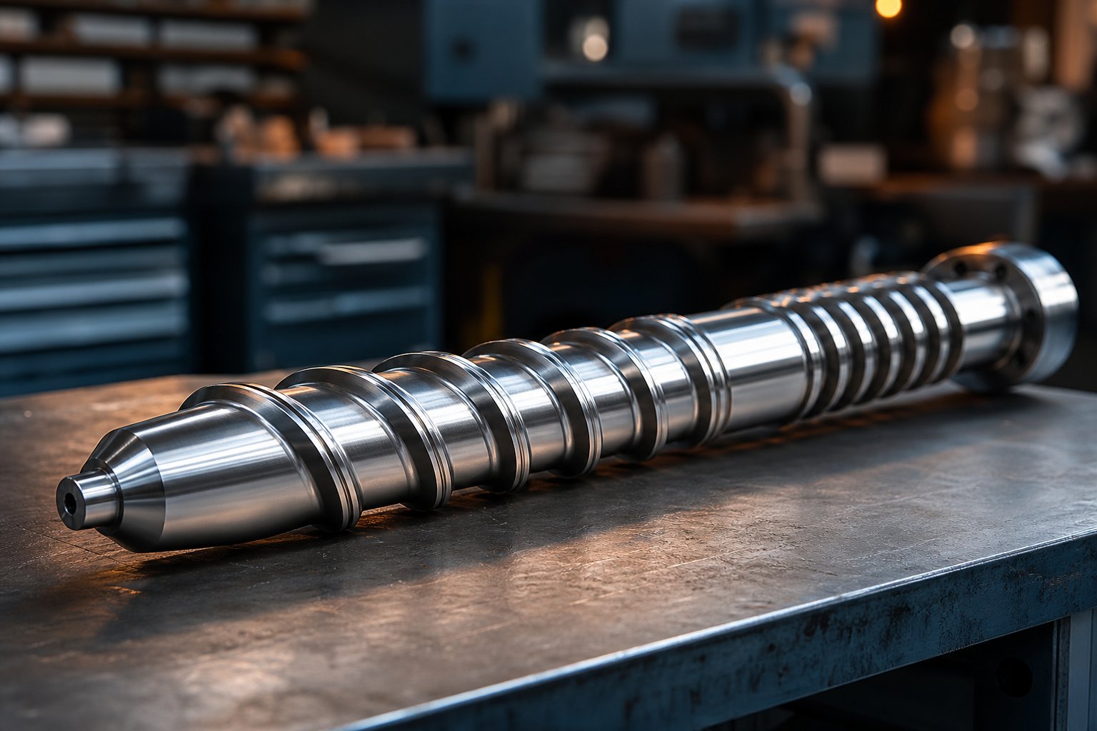
A plasticizing screw is a helical-flighted shaft rotating inside a heated barrel that conveys solid polymer pellets forward, generates frictional and shear heat to melt them, and delivers a homogeneous molten stream at controlled pressure and temperature for injection or extrusion.
Think of it as the heart of any melt-processing machine. Without it, pellets remain cold granules sitting in a hopper. With a poorly designed or worn one, you get inconsistent melt that shows up as scrap on your production floor.
The screw performs three simultaneous jobs. First, it acts as a conveyor, gripping solid pellets and pushing them forward through the barrel. Second, it functions as a heat generator — the mechanical shear between the rotating flights and the barrel wall accounts for 60-80% of the total heat input needed to melt the polymer. Third, it works as a mixer, homogenizing temperature, viscosity, and any additives into a uniform melt ready for shaping.
Injection Molding vs Extrusion Applications
How does a plasticizing screw work differently in these two environments? The distinction matters more than most operators realize.
In injection molding, the screw reciprocates — it rotates to build a shot of melt ahead of itself, then moves forward linearly like a plunger to inject that discrete dose into a mold cavity. Priorities center on shot-to-shot consistency, rapid recovery time, and precise melt temperature control within each cycle.
In extrusion, the screw rotates continuously without reciprocation, pushing a steady stream of melt through a die. Here, the emphasis shifts to sustained output rate, melt pressure stability, and long-term thermal uniformity across hours of uninterrupted operation.
Both applications rely on the same fundamental three-zone architecture, but the geometry, length ratios, and operating parameters shift based on whether you need discrete shots or continuous flow. This article covers both contexts, bridging screw design theory with the practical decisions you face when selecting, operating, or replacing these critical components.
The geometry behind those three zones — feed, compression, and metering — determines whether your screw melts material efficiently or creates the conditions for every defect in your reject bin.
Three-Zone Screw Architecture Explained in Depth
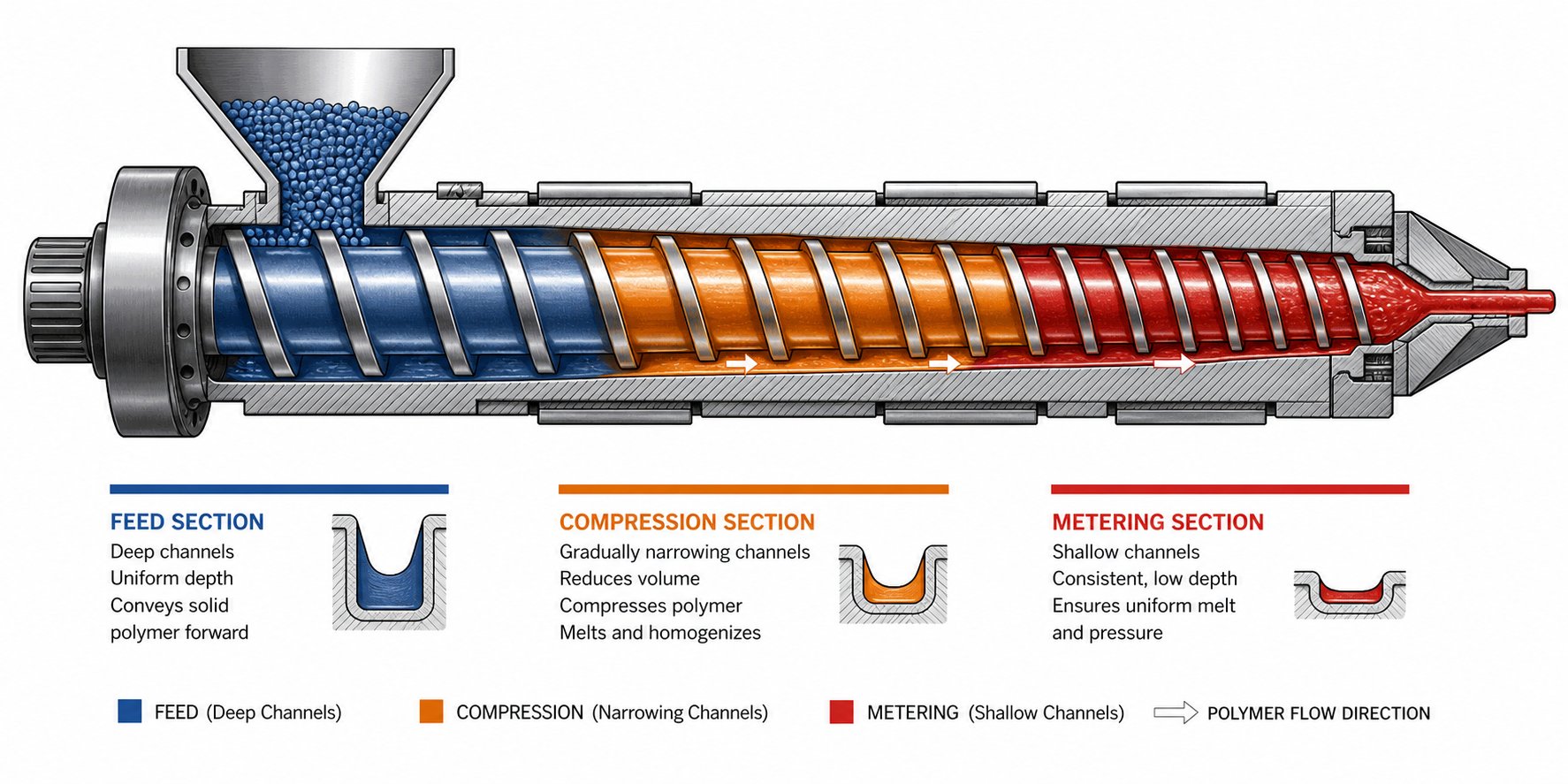
Imagine slicing your screw lengthwise and examining how the channel between flights changes from back to front. You'll notice three distinct regions — each engineered to handle a specific phase of polymer transformation. Understanding these plasticizing screw feed compression metering zones is essential because mismatched zone proportions are the root cause of most melt-quality failures.
A three zone screw design explained simply: the feed zone grabs cold pellets, the compression zone crushes and melts them, and the metering zone polishes the melt into a uniform stream. But the engineering details within each section determine whether you produce first-run parts or fill scrap bins.
Feed Zone Design and Solids Conveying Mechanics
The feed zone is the rearmost section — the first place pellets land after dropping from the hopper. Its job sounds simple: grip solid granules and push them forward. In practice, it's surprisingly nuanced.
Channel depth here is at its deepest, typically calculated as (0.12-0.14) x screw diameter. For a 60 mm screw, that translates to roughly 7.2-8.4 mm of channel depth. Why so deep? Because solid pellets have bulk density far lower than molten polymer — you need volume to accept enough material per revolution to keep downstream zones fed.
Flight geometry matters here too. The screw must create enough frictional drag against the barrel wall to push pellets forward rather than simply spinning them in place. Smooth, polished flights paired with a slightly rougher barrel bore create the differential friction that drives solids conveying.
Feed zone length varies significantly based on material type:
- Semi-crystalline polymers (PE, PP, PA): Require longer feed zones (50-65% of screw length) because their crystalline structures demand more preheating energy before melting can begin.
- Amorphous materials (PS, ABS, PC): Can use moderate feed sections (around 50%) since they gradually soften without a sharp melting point.
- Heat-sensitive resins (PVC): Use the shortest feed sections (approximately 40%) because prolonged residence at any temperature invites degradation.
When feed zone channel depth is too shallow, the screw starves downstream zones and output drops. Too deep, and screw strength suffers — a real concern on smaller diameter machines where core diameter is already limited.
Compression Zone and Melt Transition
This is where the real transformation happens. As channel depth progressively decreases from feed depth to metering depth, the solid bed gets physically compressed against the barrel wall. That compression generates intense shear heat and squeezes air pockets out of the compacting mass.
The compression zone melt transition mechanics work like this: a thin melt film forms at the barrel wall where shear is highest. As the screw rotates, flights scrape this melt film off the barrel surface and collect it into a growing melt pool on one side of the channel. Meanwhile, the solid bed shrinks as material melts from the outside in.
Transition length — how gradually the channel depth decreases — has a dramatic impact on melt uniformity:
- Gradual transitions (long compression zones): Suited for amorphous plastics and high-viscosity compounds. A slow volume reduction prevents excessive pressure spikes that could degrade sensitive materials.
- Abrupt transitions (short compression zones): Work well for low-viscosity semi-crystalline polymers like nylon that melt sharply at a defined temperature. A rapid channel reduction matches their fast solid-to-liquid conversion.
If the compression section is too short for an amorphous material, the channel volume decreases faster than the material can actually melt. The result? Pressure surges, incomplete melting, and ultimately unmelted particles in your finished parts.
Metering Zone for Melt Homogeneity
By the time material reaches the metering zone, it should be fully molten. This final section has a constant, shallow channel depth — typically (0.05-0.07) x screw diameter. For that same 60 mm screw, metering depth runs approximately 3.0-4.2 mm.
Why so shallow? The restricted channel forces the already-molten polymer through high shear, which accomplishes two things: it equalizes temperature differences between hotter and cooler melt streams, and it ensures any remaining unmixed additives or colorants get thoroughly dispersed.
The metering zone length ratio for injection screw applications is a balancing act. A longer metering section improves mixing and temperature uniformity — critical for engineering resins where tight melt temperature windows dictate part properties. But extend it too far, and excessive residence time causes thermal degradation, particularly in heat-sensitive polymers.
The table below compares typical zone length proportions across material families, based on published screw design data:
| Material Family | Feed Zone (%) | Compression Zone (%) | Metering Zone (%) | Compression Ratio |
|---|---|---|---|---|
| PS, ABS, PE, PP, PC, POM (GP screw) | 50 | 30 | 20 | 2.4 |
| PA, PBT (semi-crystalline) | 60 | 20 | 20 | 3.0 |
| PMMA | 60 | 20 | 20 | 2.2 |
| PC/ABS blend | 65 | 20 | 15 | 2.2 |
| PVC (rigid) | 40 | 40 | 20 | 2.0 |
| CA, CAB (cellulosics) | 60 | 25 | 15 | 2.2 |
Notice the pattern: PVC's exceptionally long compression zone (40%) reflects its need for gentle, gradual melting to avoid thermal breakdown. Nylon and PBT push feed zones longer (60%) to accommodate the extra energy needed to melt crystalline structures, while their abrupt melting behavior allows a short 20% compression section.
These proportions aren't arbitrary — they represent decades of empirical optimization matching screw geometry to polymer physics. A general-purpose screw splits roughly 50/30/20 because that ratio handles the broadest range of commodity resins acceptably. But "acceptably" and "optimally" are different standards, which raises a critical question: how do the individual geometric parameters within these zones — compression ratio, L/D ratio, flight depth — interact to fine-tune performance for your specific application?
Critical Screw Geometry Parameters and How They Interact
Every parameter on a plasticizing screw exists in relationship to others. Change one dimension and you shift the entire melting dynamic. The problem? Most technical references define these values in isolation, leaving you to guess how they connect. Here, you'll find them presented as a unified system — because that's exactly how they behave inside your barrel.
Compression Ratio and Its Impact on Melt Quality
The plasticizing screw compression ratio calculation is straightforward: divide the feed zone channel depth by the metering zone channel depth. A screw with 8 mm feed depth and 3.2 mm metering depth gives you a compression ratio of 2.5:1. Simple math — but the performance implications are anything but simple.
How compression ratio affects melt quality comes down to polymer physics. Semi-crystalline materials like PE, PP, and nylon undergo a dramatic density increase as crystallites collapse during melting. Their solid-to-melt volume change can reach 20-30%, meaning the screw must physically squeeze more solid volume into less channel space to maintain a full, pressurized melt pool. That's why these resins typically demand compression ratios between 3.0:1 and 4.5:1.
Amorphous polymers like ABS, polycarbonate, and polystyrene behave differently. They soften gradually without a sharp phase change, and their density shift during transition is minimal — often under 10%. Lower ratios in the 2.0:1 to 2.8:1 range provide adequate compression without generating excessive shear heat that could degrade the material.
Get this wrong and you face two failure modes:
- Compression ratio too low for the resin: Insufficient pressure on the melt film means unmelted particles survive past the compression zone. You'll find them as specs, gels, or weak spots in finished parts.
- Compression ratio too high for the resin: Excessive shear generates heat faster than conduction can remove it. Localized melt temperatures spike, causing thermal degradation — visible as brown streaks, burns, or brittleness in heat-sensitive grades like PVC or POM.
PVC illustrates this perfectly. With a recommended compression ratio of only 1.5:1 to 2.0:1, it demands the gentlest volume reduction of any common polymer. Run PVC on a 3.5:1 general-purpose screw and degradation begins almost immediately — releasing corrosive hydrochloric acid that attacks your barrel from the inside out.
L/D Ratio, Pitch, and Channel Geometry Relationships
The L/D ratio for injection molding screw applications defines total flighted length divided by the screw's outer diameter. A 60 mm screw that's 1,200 mm long has a 20:1 L/D. This single number tells you how much working length the polymer has for heating, compressing, and homogenizing before it reaches the screw tip.
Longer screws (higher L/D) provide gentler melting because the same compression ratio is spread across more distance. Research into melting mechanics confirms that higher melting rates require either higher screw speed or longer melting sections when dealing with simple flighted designs. A 24:1 screw can achieve the same melt quality as a 20:1 screw at lower RPM — reducing shear-generated heat and extending processing windows for sensitive resins.
Standard injection molding screws fall between 18:1 and 24:1 L/D. Extrusion screws extend further, sometimes reaching 36:1, because continuous operation justifies the additional barrel length for improved homogeneity.
The screw flight depth and pitch relationship is where geometry gets interconnected. Here's a scannable reference for the key parameters:
- Pitch: The axial distance between adjacent flights. Standard ("square pitch") equals one screw diameter — so a 60 mm screw has 60 mm pitch. Increasing pitch boosts conveying rate but reduces shear and residence time.
- Helix angle: The angle of the flight relative to a plane perpendicular to the screw axis. Standard square pitch produces a helix angle of approximately 17.66 degrees. Steeper angles (larger pitch) move material faster but reduce the down-channel velocity component that drives melting.
- Channel width: The perpendicular distance between adjacent flights minus the flight land width. Wider channels increase volumetric capacity but reduce shear rate at any given RPM.
- Flight depth (channel depth): The radial distance from the screw root to the flight tip. Deeper channels in the feed zone (typically 0.12-0.14 x diameter) accommodate low-bulk-density pellets. Shallower metering depths (0.05-0.07 x diameter) maximize shear for homogenization.
- Flight width (land width): The axial thickness of the flight at its tip. Usually about 10% of the screw diameter. Wider lands increase wear surface area but reduce channel volume.
- L/D ratio range: 18:1 to 24:1 for injection molding; up to 36:1 for extrusion. Higher values favor engineering resins, color mixing, and vented designs.
- Compression ratio range: 1.5:1 (PVC) to 4.5:1 (high-crystallinity nylon, POM). Must match polymer density change during melting.
These parameters don't operate independently. A deep-channeled feed zone paired with a shallow metering section produces a high compression ratio — but if that transition happens over a short compression zone length, you get aggressive, abrupt melting. Spread the same ratio over a longer transition, and melting proceeds gradually. The interplay between depth change and zone length is what distinguishes a well-designed screw from one that merely hits a target compression number on paper.
Similarly, pitch interacts with channel depth to determine the actual volume of material processed per revolution. Two screws with identical compression ratios but different pitches will produce different output rates, different shear histories, and different melt temperature profiles — even when running the same polymer at the same RPM.
Geometry sets the boundaries of what your screw can achieve. But within those boundaries, the specific polymer you're processing determines whether a given design excels or struggles — a reality that drives material-specific screw selection.
Material-Specific Screw Selection for Optimal Processing
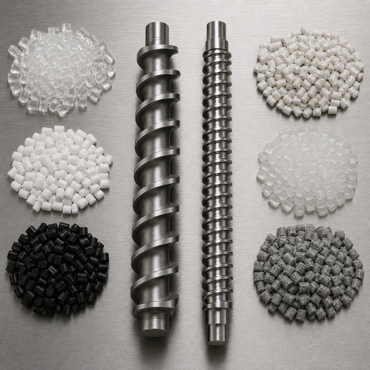
A general-purpose screw processes many resins adequately — but "adequate" is a low bar when you're chasing tight tolerances, consistent color, and zero rejects. The polymer you run dictates a specific set of melting behaviors, viscosity profiles, and thermal sensitivities. Match your screw geometry to those demands, and quality issues often disappear without touching a single machine parameter.
So how should screw geometry change depending on the polymer being processed? The answer lies in three material characteristics: density change during melting, thermal sensitivity, and abrasiveness.
Screw Design for Polyolefins and Semi-Crystalline Resins
Polyethylene and polypropylene are the workhorses of injection molding — and they demand specific screw characteristics that general-purpose designs often compromise on. The best screw design for polyolefins PE PP accounts for one defining physical property: the dramatic density change that occurs when crystallites collapse during melting.
Solid PE pellets have a bulk density far lower than molten PE. As crystalline regions melt, the polymer volume shrinks significantly — sometimes 20-30%. The screw must compress that declining volume aggressively to maintain a pressurized melt pool and prevent air entrapment. That's why polyolefins benefit from higher compression ratios, typically in the 3.0:1 to 4.0:1 range.
Unfilled polypropylene, for example, performs well with volumetric compression ratios of 3.5 to 3.75:1. Pair that with a deeper feed section — necessary to accept the low-bulk-density pellets at sufficient volume per revolution — and a relatively abrupt compression zone that matches polyolefins' sharp melting point, and you have a screw optimized for this material family.
Nylon (PA) and PBT share similar semi-crystalline demands. Their defined melting temperatures mean the solid-to-melt transition happens fast once adequate energy accumulates. A longer feed zone (around 60% of total length) builds enough preheat energy, then a shorter, more aggressive compression zone matches the rapid phase change without over-shearing the already-thin melt.
Processing PVC, Filled Materials, and High-Temperature Polymers
PVC sits at the opposite end of the processing spectrum. It's thermally sensitive, prone to releasing hydrochloric acid when overheated, and unforgiving of aggressive shear. A PVC plasticizing screw low compression ratio — typically between 1.5:1 and 2.5:1 for rigid formulations — prevents localized overheating that triggers degradation. The compression zone must be long and gradual, spreading volume reduction across more screw length to keep shear rates below the threshold where PVC begins to decompose.
Beyond geometry, PVC screws require corrosion-resistant materials. The hydrochloric acid released during processing attacks standard steel aggressively, making nickel alloys, stainless steels, or PVD coatings essential for barrel and screw components in PVC applications.
Glass-filled compounds present a different challenge. The screw geometry for glass filled polymers must account for two realities: the filler doesn't melt, and it's intensely abrasive. Since non-compressible fillers occupy channel volume without undergoing phase change, compression ratios drop compared to the same neat resin. A 40% talc-filled polypropylene typically uses a 2.75 to 3.25:1 ratio — noticeably lower than the 3.5-3.75:1 appropriate for unfilled PP. Shallower channels and wear-resistant coatings (tungsten carbide, bimetallic liners) become mandatory rather than optional.
PEEK and other high-temperature polymers push equipment to its limits. PEEK high temperature polymer screw requirements stem from its melting point of approximately 343 degrees C and processing temperatures of 370-400 degrees C. At these extremes, standard screw steels lose hardness, seals fail, and thermal management becomes critical. Specialized barrel and screw materials rated for sustained high-temperature operation are non-negotiable. Carbon-filled and glass-filled PEEK grades compound the difficulty — they increase viscosity, demand higher injection pressures, and accelerate wear on flight lands.
When to Upgrade from General-Purpose to Specialized Screws
How do you know when to replace a general purpose screw with a specialized design? The material itself will tell you — through your reject rate, cycle time, and part consistency. Watch for these performance indicators:
- Inconsistent melt temperature: Shot-to-shot variation exceeding +/- 5 degrees C suggests the screw geometry isn't matched to the material's melting behavior.
- Visible unmelted particles or gels: A compression ratio too low for your resin leaves solid material surviving into the metering zone.
- Thermal degradation signs: Brown streaks, black specks, or brittleness indicate excessive shear or residence time — common when running heat-sensitive resins on high-compression screws.
- Barrel temperature overrides: When barrel zone heaters cannot maintain setpoint due to viscous heating, the screw geometry is forcing the material through channels too restrictive for its current state.
- Excessive scrap rates above 3-5%: If process parameter adjustments cannot bring scrap down, the fundamental geometry may be mismatched to the material.
The table below summarizes recommended screw characteristics across major material families:
| Material Family | Compression Ratio | Feed Zone Length | Transition Type | Special Requirements |
|---|---|---|---|---|
| PE, PP (unfilled) | 3.0-3.75:1 | 50-60% | Moderate to abrupt | Deep feed section for low bulk density |
| PA, PBT (semi-crystalline) | 3.0-4.0:1 | 55-65% | Short, abrupt | Higher melt temps, quick phase change |
| ABS, PC (amorphous) | 2.0-2.8:1 | 45-55% | Gradual | Uniform shear, no sharp melt point |
| Rigid PVC | 1.5-2.5:1 | 35-45% | Very gradual (long) | Corrosion-resistant materials, low shear |
| Glass/mineral-filled compounds | 2.5-3.25:1 (varies by fill level) | 50-60% | Moderate | Wear-resistant coatings, generous barrier gaps |
| PEEK, PPS (high-temp) | 2.5-3.5:1 | 50-55% | Moderate | High-temp rated metallurgy, elevated barrel capacity |
Notice that compression ratio alone doesn't define the screw — transition length, feed zone proportion, and material construction all shift together. A screw optimized for PVC differs from one built for nylon in every dimension, not just channel depth ratios.
If your production runs multiple material families on the same machine, a general-purpose screw represents a compromise. For dedicated lines running a single polymer group, investing in a material-matched geometry typically pays back within months through reduced scrap, faster cycles, and fewer parameter-chasing headaches. The screw materials themselves — nitrided steel, bimetallic construction, hard-facing alloys — become equally important when abrasive or corrosive polymers enter the picture.
Screw Materials and Surface Treatments for Wear Resistance
Geometry tells the screw how to melt your polymer. Metallurgy determines how long it can keep doing so. You can specify the perfect compression ratio, dial in ideal zone proportions, and match every dimension to your resin — but if the screw material can't withstand the mechanical and chemical punishment your polymer delivers, that optimized geometry erodes away one production hour at a time.
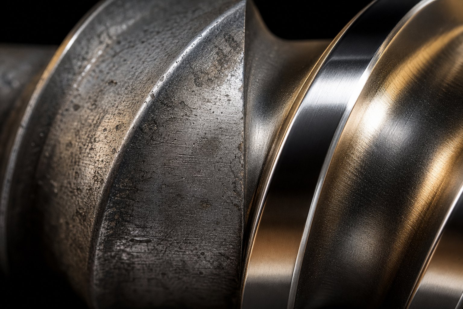
As Plastics Technology explains, wear begins the instant the screw starts rotating inside the barrel. The original clearances between flight outside diameter and barrel bore are minimal — typically just 0.001 inch per side, per inch of diameter. As those clearances increase through wear, melting efficiency drops, shot consistency degrades, and operators start chasing parameters to compensate. Choosing the right screw material and surface treatment for your application is what separates a component that lasts years from one that fails in months.
Nitrided Steel, Bimetallic, and Hard-Facing Options
Think of screw metallurgy as a hierarchy — each tier offering greater protection at greater cost. The key is matching the tier to the severity of your processing environment.
Standard nitrided steel (4140/4340) sits at the entry level. The base steel is heat-treated and then gas-nitrided, a thermochemical process that diffuses nitrogen into the surface to create a hard case layer. This treatment produces surface hardness around 65-70 HRC across a thin depth, providing decent resistance against general-purpose extrusion and molding of unfilled commodity resins like PE, PP, and PS. For shops running clean, unfilled polyolefins on moderate cycles, nitrided 4140 delivers reliable performance at the lowest cost per screw. But push it into glass-filled nylon or mineral-loaded compounds, and that thin hardened layer wears through quickly.
Bimetallic construction steps up significantly. Here, a wear-resistant alloy — commonly nickel- or cobalt-based materials like Colmonoy 56 or Stellite — is applied to the flight lands or centrifugally cast into the barrel bore. The result is a component with a tough, ductile core and an extremely hard working surface. Industry data suggests bimetallic screws can extend service life by up to five times compared to standard nitrided steel when processing abrasive plastics. For filled polymers, recycled streams with contaminants, or high-output production where downtime costs thousands per hour, bimetallic construction quickly justifies its premium.
Tungsten carbide hard-facing represents the top tier. Applied to screw flight lands via welding or thermal spray, tungsten carbide delivers hardness exceeding 70 HRC with outstanding resistance to abrasive wear. Imagine processing 40% glass-filled PA66 at high volumes — the glass fibers act like microscopic cutting tools against every surface they contact. A tungsten carbide hard facing injection screw survives this environment far longer than any nitrided or standard bimetallic alternative, making it the go-to choice for the most demanding filled-resin applications.
One critical detail processors often overlook: screw and barrel materials must be compatible. Running a soft screw inside an extremely hard barrel — or vice versa — creates conditions for adhesive wear and galling. Alloys with lower tungsten carbide content may be easier to apply and finish, but they offer less abrasion resistance and have a greater tendency to gall when paired with the hardest barrel linings.
Surface Treatments and Coatings for Extended Wear Life
Beyond base material selection, surface treatments add another layer of defense — sometimes literally. These coatings target specific wear mechanisms that your polymer and filler system impose on the screw.
Chrome plating provides a smooth, low-friction surface with moderate hardness and good corrosion resistance. It's particularly useful for processing PVC and other chlorine-containing polymers where chemical attack is the primary threat. The chrome layer reduces polymer adhesion, eases cleaning during material changeovers, and resists the corrosive byproducts that acidic resins generate during melting.
PVD (Physical Vapor Deposition) coatings — including titanium nitride (TiN) and chromium nitride (CrN) — deposit an ultra-thin, extremely hard film onto the screw surface. These coatings excel in applications requiring both wear and corrosion resistance without significantly altering flight dimensions. They're particularly effective for engineering resins processed at elevated temperatures where traditional chrome plating may soften or delaminate.
Specialized alloy overlays — such as nickel-boron or cobalt-chromium weld deposits — are applied selectively to high-wear areas like flight lands and root surfaces in the compression zone. These overlays can be tailored to specific wear profiles: high-nickel alloys for corrosive environments, high-carbide alloys for abrasive ones.
Selecting the right protection starts with identifying which wear mechanism dominates your application. Here's a structured breakdown:
- Adhesive wear — Metal-to-metal contact between screw flights and barrel wall causes micro-welding and tearing of surface material.
- Common causes: Misaligned screw and barrel, poor concentricity, solids wedging from mismatched screw design, deflection under high pressures.
- Recommended protection: Ensure compatible screw/barrel alloy pairing; use flight-land hard-facing (Stellite, Colmonoy 56); verify alignment at installation.
- Abrasive wear — Hard particles in the melt stream physically cut and erode metal surfaces, removing material from flights, barrel bore, and channel root.
- Common causes: Glass fibers, mineral fillers (talc, calcium carbonate), flame retardants, contaminated regrind, tramp metal from improper material handling.
- Recommended protection: Tungsten carbide hard-facing on flights; bimetallic barrels with high-carbide inlay; screw surface treatment for abrasive polymers using thermal spray or weld overlay coatings.
- Corrosive wear — Chemical attack from acidic byproducts or moisture-driven reactions degrades the metal surface, weakening it and accelerating mechanical wear.
- Common causes: PVC releasing hydrochloric acid, fluoropolymers generating hydrofluoric acid, moisture in hygroscopic resins (PET, nylon) causing hydrolytic attack at elevated temperatures.
- Recommended protection: Corrosive wear resistance screw coatings including nickel-based alloys (Hastelloy, Inconel), chrome plating, or PVD coatings; bimetallic barrels with corrosion-resistant alloy linings; proper resin drying before processing.
Many real-world applications involve more than one wear type simultaneously. A glass-filled PVC compound, for example, delivers both abrasive and corrosive attack — demanding a screw that combines hard-facing on the flights with a corrosion-resistant base alloy. Understanding which mechanisms your specific resin and filler system activate is the first step toward specifying a screw that holds its geometry long enough to deliver consistent parts.
Metallurgy protects the screw's physical integrity, but it can't compensate for poor operating practices. The way you set screw speed, back pressure, and stroke length determines how much stress that screw actually endures — and whether it reaches its full service life or wears out prematurely.
Operating Parameters That Maximize Plasticizing Performance
You've selected the right geometry and matched your screw metallurgy to the resin. But none of that matters if your plasticizing screw speed and back pressure settings fight against each other instead of working in harmony. These parameters don't operate as independent dials — they interact with your screw's geometry and your polymer's thermal limits in ways that either amplify quality or multiply defects.
Screw Speed and Back Pressure Interaction with Geometry
Imagine cranking up screw RPM to shorten recovery time. What actually happens inside the barrel? Each revolution drags polymer across flight lands and barrel walls, generating frictional heat proportional to rotational speed. The screw RPM shear heating relationship is roughly linear — double the speed, and you roughly double the shear energy input into the melt. For heat-sensitive materials like PVC or POM, this means a narrow safe operating window before degradation begins.
But RPM doesn't act alone. RJG notes that screw speed should be selected based on material type and additive content, ensuring the correct amount of shear is provided by the combination of rotation and screw geometry. A deep-channeled screw at high RPM generates less shear than a shallow-channeled one at the same speed — geometry mediates the relationship between rotation and heat generation.
Back pressure adds another dimension. How back pressure affects melt homogeneity comes down to residence and compression. As Huarong's technical guidance explains, back pressure is the reverse pressure applied to the screw during plastication as it rotates and retracts to accumulate molten polymer. Increasing it forces the screw to work harder to push melt forward, which:
- Compresses the molten plastic to higher density
- Increases shear and mixing energy within the channels
- Promotes uniform temperature and viscosity distribution
- Helps expel trapped air and volatile moisture
- Stabilizes melt density before injection
The consequence? Higher back pressure improves shot weight consistency and color dispersion — but at the cost of increased residence time, elevated melt temperature, and greater screw torque demand. Push too far, and you'll see degradation, burning, or excessive cycle times that erase any quality gains.
Here's where the interaction becomes critical: high RPM combined with high back pressure is a recipe for overheating. The screw generates more shear heat while simultaneously holding the melt in the barrel longer. For glass-filled materials, slightly elevated back pressure aids fiber dispersion. For transparent or optical-grade resins, moderate settings prevent haze and internal bubbles. For foamed or microcellular processes, lower back pressure protects the cell structure.
Recovery Time, Stroke Length, and Cycle Optimization
Screw recovery time optimization is where these parameters converge with production economics. Recovery time — the seconds your screw needs to rotate, melt polymer, and build the next shot — directly limits your cycle. Too slow, and the mold sits closed waiting on plastication. Too fast (from excessive RPM), and melt quality suffers.
The relationship between screw diameter and shot volume introduces a constraint most operators underestimate. The 1-3D stroke length rule injection molding practitioners rely on states that optimal injection stroke should fall between 1 and 3 times the screw diameter for a given shot size. A 50 mm screw, for example, should ideally inject with a stroke between 50 mm and 150 mm.
The 1D to 3D stroke rule ensures that the screw processes enough material per cycle to maintain fresh melt without exceeding the residence time that causes thermal degradation — too short a stroke leaves stale melt in front of the screw, while too long a stroke creates inconsistent plasticizing conditions across the shot volume.
Why does violating this rule cause shot-to-shot variation? When the stroke is less than 1D, a large cushion of previously melted material sits in the barrel across multiple cycles, accumulating heat history. Sensitive polymers degrade. When stroke exceeds 3D, the screw retracts so far that the feed zone may lose consistent pellet intake, and the enormous melt volume ahead of the screw tip becomes difficult to keep thermally uniform from front to back.
As Skiba Inc. explains, applying this approach requires calculating shot volume based on melt density — not solid density — and then checking which screw diameters place your required stroke within that 1D-3D window. This is the first step in evaluating screw size, followed by residence time, recovery rate, and injection pressure considerations.
For operators looking to systematically optimize plastication without guesswork, structured adjustment sequences eliminate trial-and-error frustration. Follow this checklist in order — skipping steps or adjusting parameters simultaneously makes root-cause identification impossible:
- Verify stroke falls within 1-3D range — If not, you may be on the wrong screw diameter for your shot size. Address this before touching any other parameter.
- Establish baseline at minimum practical back pressure — Start low, confirm stable screw retraction, and document shot weight at this baseline.
- Set screw speed for complete melting without overheating — Find the RPM that achieves full melt with acceptable recovery time. Watch melt temperature — if it rises more than 10-15 degrees C above barrel setpoint, RPM is too high for your geometry.
- Increase back pressure in small increments (approximately 50 psi per step) — After each adjustment, weigh five consecutive shots. When shot weight variation tightens and melt appearance improves (no unmelted specs, uniform color), you're approaching the optimal zone.
- Confirm no degradation signs — Check for brown streaks, odor, or brittleness. If present, reduce back pressure or RPM.
- Evaluate recovery time against cooling time — Recovery should complete before mold open. If it doesn't, modest RPM increase is preferable to excessive back pressure reduction.
- Document and lock parameters — Record the final combination of RPM, back pressure, and resulting recovery time on your process sheet to prevent shift-to-shift drift.
The objective remains constant: use the lowest back pressure and screw speed combination that still delivers homogeneous melt and stable shot weight. Every increment beyond that minimum adds unnecessary thermal stress to both the polymer and the screw itself — shortening component life while providing diminishing quality returns.
When these parameters are dialed in correctly but parts still show defects — unmelted particles, color streaks, or progressive quality deterioration — the screw's physical condition rather than its settings becomes the prime suspect.
Troubleshooting Plasticizing Problems Traced to Screw Condition
You've verified your process parameters. Back pressure is stable, RPM is within range, and barrel temperatures hit setpoint consistently. Yet unmelted particles keep showing up in parts, color dispersion remains uneven, and shot weight drifts between cycles. Sound familiar? These are the telltale fingerprints of a plasticizing screw that's either geometrically mismatched or mechanically worn beyond its effective limits.
The frustrating reality is that screw wear is a gradual process. As Plastics Technology notes, it can go unnoticed until performance is greatly reduced — because operators instinctively compensate by tweaking machine settings. By the time those compensations stop working, the screw may be severely degraded.
Diagnosing Unmelted Particles and Poor Color Dispersion
Finding unmelted particles in injection molding traces back to one fundamental failure: the polymer didn't receive enough shear energy or compression to fully transition from solid to melt before reaching the screw tip. Three root causes dominate:
- Symptom: Unmelted pellets or gels visible in molded parts
Cause: Insufficient compression ratio for the resin being processed — the channel volume doesn't decrease enough to generate adequate melt-film pressure against the barrel wall
Solution: Verify compression ratio matches material requirements (see material-specific table in previous section). If running a general-purpose screw on semi-crystalline resins requiring 3.0:1+ ratios, upgrade to a material-matched design - Symptom: Unmelted particles appearing progressively over weeks or months
Cause: Metering zone flight wear increasing radial clearance — melt leaks backward over worn flights instead of being pushed forward, reducing effective compression and shear in the metering section
Solution: Measure flight OD at multiple points along the metering zone. If clearance exceeds tolerance thresholds, schedule screw refurbishment or replacement - Symptom: Unmelted specs that appear only at higher production speeds
Cause: Excessive screw RPM pushing material through compression and metering zones faster than thermal energy can penetrate the solid bed. The residence time drops below what's needed for complete melting
Solution: Reduce RPM and increase back pressure to extend melt residence. If cycle time constraints don't allow slower recovery, a longer L/D screw or barrier-flight design may be required
Poor color dispersion — streaks, swirls, or inconsistent shade across parts — points specifically to the metering zone. This is where the final homogenization should occur. When the poor color dispersion screw metering zone issue arises, it typically means one of two things: either the metering section is too short to provide adequate mixing revolutions, or wear has opened up flight clearances so severely that melt bypasses the high-shear zone entirely.
Think of it this way: color concentrate disperses through shear forces that physically break down pigment agglomerates and distribute them uniformly. A worn metering zone with excessive clearance reduces those shear forces because melt takes the path of least resistance — flowing backward over degraded flights rather than being forced through the narrow gap between flight land and barrel wall where shear is highest.
Identifying Worn Screws and Knowing When Replacement Is Critical
How to tell when a plasticizing screw needs replacement isn't always obvious — especially if you haven't pulled the screw for inspection recently. But the machine gives you signals long before catastrophic failure occurs. Watch for this progression of symptoms:
- Symptom: Gradually increasing recovery time at the same RPM and back pressure settings
Cause: Worn flights lose pumping efficiency. As radial clearance grows, leakage flow increases — material recirculates over flights instead of advancing forward
Solution: Document recovery time trends. A 15-20% increase from baseline warrants pulling the screw for measurement - Symptom: Short shots or inconsistent fill patterns that resist parameter adjustments
Cause: Worn check valve and/or screw flights cannot maintain pressure during injection. Worn screws and check valves allow backflow during injection, reducing effective shot volume unpredictably
Solution: Perform a check ring seal test (inject against a blocked nozzle and observe screw drift). Replace worn valve components and evaluate screw flight condition simultaneously - Symptom: Rising melt temperature despite stable barrel setpoints
Cause: Operators increase RPM to compensate for lost output from worn flights. Higher RPM generates more shear heat. Additionally, melt leaking over worn flights experiences excessive shear in the enlarged clearance gap
Solution: Compare actual vs. set melt temperature. If the differential has grown over time without parameter changes, screw wear is the likely driver - Symptom: Degraded part surface finish — increasing flow marks, splay, or dull surfaces
Cause: Inconsistent melt viscosity from poor mixing in worn metering section. Temperature variations create visible flow inconsistencies during fill
Solution: Inspect metering zone flights and mixing elements for wear. Dispersive mixing features are particularly susceptible to degradation because their undercut geometry wears rapidly under normal conditions - Symptom: Black specks or charred material appearing in parts
Cause: Root wear creates pockets and dead spots where material hangs up and thermally degrades over time. As industry experts explain, root wear is most extreme on the forwarding side of flights in high-pressure zones
Solution: Pull screw immediately. Inspect root surfaces for erosion, pitting, or material buildup. Clean thoroughly and evaluate whether rebuild is viable
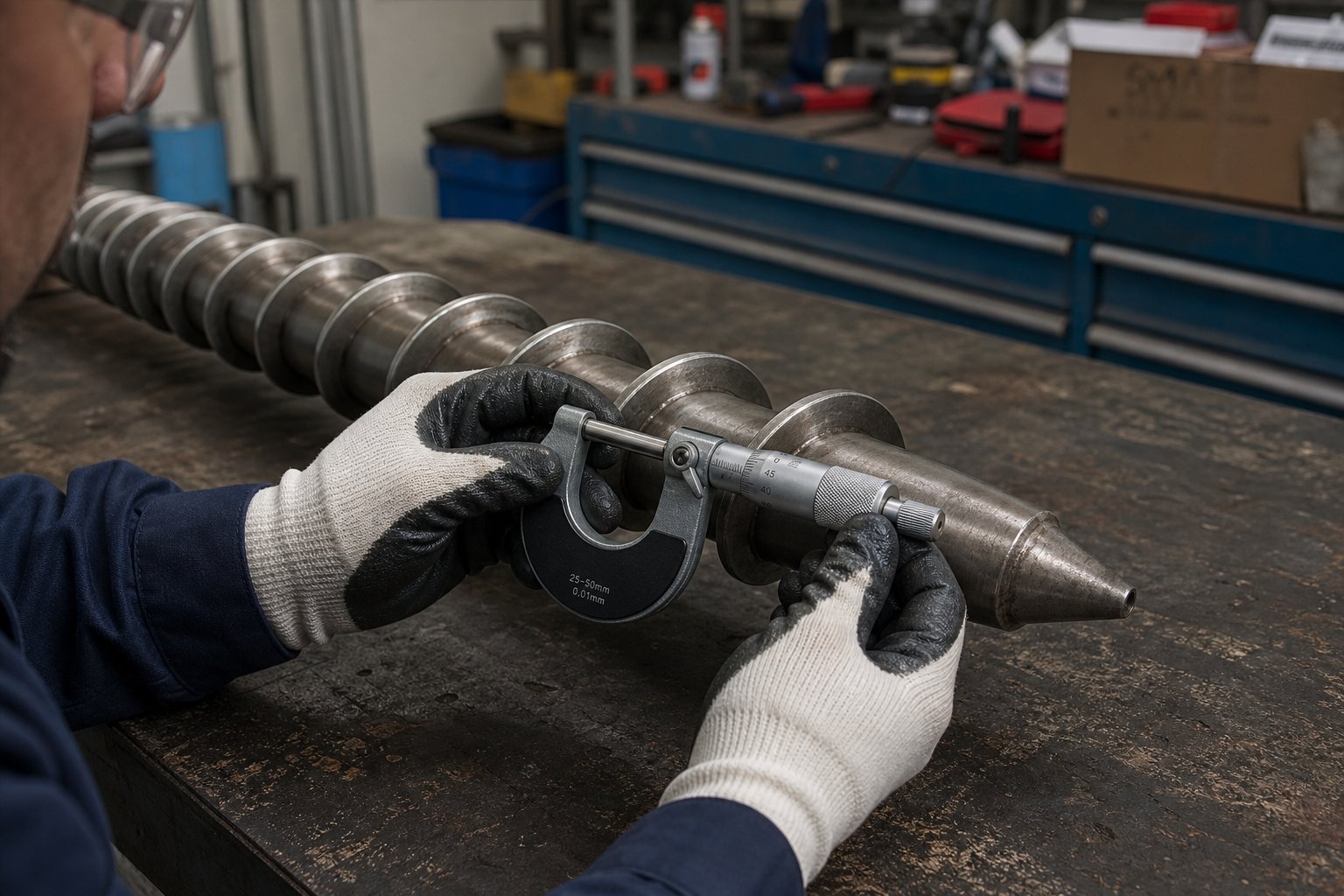
The screw flight diameter wear measurement method requires precision tools — typically an outside micrometer or a go/no-go gauge calibrated to the original OD specification. Measure at multiple points along the screw length, paying particular attention to the transition section and last few turns of metering where the highest pressures and temperatures cause the most severe OD wear.
A common rule of thumb considers flight clearance reaching four times the original tolerance as the replacement threshold. For context, industry guidelines suggest that once wear exceeds 0.2-0.3 mm beyond nominal clearance (depending on machine size), output and quality decline significantly. However, resin viscosity matters — a higher-viscosity polymer like HDPE tolerates more clearance before leakage flow becomes critical, while a low-viscosity material like polypropylene suffers output loss much sooner at the same wear level.
The financial impact of continuing to process on a worn screw is often invisible until you calculate it. Every percentage point of increased scrap, every kilowatt-hour of additional energy consumed to maintain output at higher RPM, and every cycle-time second added while the mold waits for recovery — these costs accumulate silently. Many plants squeeze every last hour from worn equipment to avoid downtime, but as one analysis demonstrates, the hidden costs of increased energy consumption and material waste can far exceed the cost of scheduled replacement or rebuild.
Establishing baseline measurements when a screw is new — and re-measuring at planned intervals — transforms reactive emergencies into predictable maintenance events. You'll know exactly when your screw crosses from "compensatable" wear into territory where quality and cost penalties exceed replacement investment. That knowledge puts you in control of the timeline rather than letting the screw dictate it through catastrophic failure or unacceptable scrap rates.
Knowing your screw needs replacement is only half the equation. Translating that knowledge into a clear specification — one that communicates exactly what you need to a manufacturer — is where many maintenance teams struggle.
Screw Specification Checklist for Ordering Replacements
Pulling a worn screw and knowing it needs replacement is the easy part. Communicating exactly what you need to a manufacturer — in language that results in a component optimized for your specific application — is where many maintenance teams lose time, money, and production days. A vague order like "same as before, but better" rarely yields the improvement you're after.
Whether you're sourcing a direct replacement or upgrading to a material-specific design, a structured injection molding screw specification checklist eliminates miscommunication and ensures your new component arrives ready to perform from the first shot.
Essential Specifications to Document Before Ordering
Before contacting any supplier, gather the following information. Missing even one critical dimension can delay quoting, cause manufacturing errors, or result in a screw that doesn't match your barrel assembly.
- Identify your machine make, model, and year — This tells the manufacturer the barrel bore diameter, mounting interface, drive spline or keyway configuration, and any machine-specific constraints on overall length.
- Measure and record screw diameter — Confirm the nominal OD from your machine manual. If you're measuring a worn screw, note that current dimensions may be below spec.
- Confirm L/D ratio and overall flighted length — Count the number of flights or measure total length from the feed pocket to the screw tip seat. Verify against original equipment documentation.
- Document current compression ratio — Measure feed zone channel depth and metering zone channel depth on the existing screw. Even if worn, these measurements indicate what design you've been running.
- List primary material(s) processed — Include specific grades if possible (e.g., "30% glass-filled PA66" rather than just "nylon"). Filler type and loading percentage directly affect geometry and metallurgy recommendations.
- Record shot size range and typical cycle time — This helps the manufacturer verify that your stroke falls within the 1-3D window and that recovery rate matches your cycle demands.
- Note known wear patterns or failure modes — Where did the old screw wear fastest? Were there corrosion signs, abrasive scoring on flights, or root erosion in specific zones? This history guides material selection for the replacement.
- Specify check valve type and tip geometry — The non-return valve must mate precisely with the screw tip. Provide the existing valve style (ring, ball, or poppet) and dimensions.
Communicating Performance Requirements to Screw Manufacturers
Raw dimensions get you a physical replacement. But if you want performance improvement, you need to translate your processing problems into specification language that custom screw barrel manufacturer requirements demand. Here's how to bridge that gap:
Instead of saying "we get unmelted particles," specify: "Require higher compression ratio or barrier geometry to achieve complete melting of HDPE at 180 RPM within 4.5-second recovery window." Instead of "color mixing is poor," communicate: "Need enhanced dispersive mixing capability in the metering section for 2% masterbatch letdown ratio without extending cycle time."
The screw barrel replacement specifications template below provides a structured format you can fill out and send directly to any qualified supplier:
| Specification Field | Your Data | Example Entry |
|---|---|---|
| Machine make/model | _______________ | Engel Victory 200/80 |
| Screw diameter (mm) | _______________ | 45 mm |
| L/D ratio | _______________ | 22:1 |
| Overall flighted length (mm) | _______________ | 990 mm |
| Current compression ratio | _______________ | 2.5:1 (requesting upgrade to 3.2:1) |
| Primary resin(s) | _______________ | PP copolymer + 20% talc fill |
| Shot size range (g) | _______________ | 85-120 g per cycle |
| Target melt temperature (C) | _______________ | 220-235 C |
| Cycle time target (s) | _______________ | 18 s total, 6 s recovery max |
| Required mixing capability | _______________ | Dispersive mixing section for color concentrate |
| Wear resistance needs | _______________ | Bimetallic or tungsten carbide flights (abrasive filler) |
| Known issues with previous screw | _______________ | Flight OD wear in metering zone after 14 months; color streaks at startup |
| Check valve type/dimensions | _______________ | Ring-style, 44.5 mm OD, 62 mm length |
| Drive connection | _______________ | Splined shaft, 6-tooth, 35 mm root diameter |
Filling out this template accomplishes two things. First, it forces your team to document the current state — creating a baseline record that's invaluable for future maintenance planning. Second, it gives manufacturers enough information to recommend geometry improvements rather than simply duplicating a design that may have been suboptimal from the start.
For teams evaluating how to order a replacement plasticizing screw with performance upgrades rather than like-for-like copies, look for suppliers that offer engineering consultation as part of the quoting process. Manufacturers like NANHAIYA provide custom screw barrel engineering with in-house R&D capabilities and technical support — helping translate your processing challenges into optimized replacement components rather than generic catalog parts. Their injection molding screw barrel catalog serves as a practical resource for maintenance teams comparing specifications, material options, and design configurations when evaluating replacement alternatives.
The difference between a transactional parts order and an engineered solution often comes down to this specification step. A supplier with custom manufacturing capabilities can review your completed template, identify where geometry or metallurgy changes would address your documented issues, and propose modifications backed by processing data — turning a routine replacement into a measurable performance upgrade.
Next Steps for Optimizing Your Plasticizing System
Having the right specification template means nothing if you don't know which action to take first. Every shop floor sits in a different place — some fighting active quality failures, others running smoothly but sensing the slow creep of wear. Your long term plasticizing system optimization strategy depends on correctly diagnosing where you stand right now.
Matching Your Priority to the Right Action
Think of your situation as falling into one of three paths:
- Path 1 — Active quality issues (splay, unmelts, color streaks): Revisit operating parameters first. Verify back pressure, RPM, and stroke length fall within recommended ranges. If adjustments don't resolve defects, inspect screw condition using the measurement methods and symptom lists covered in the troubleshooting section. Often, parameter drift masks underlying wear that's been building for months.
- Path 2 — Confirmed screw wear or damage: The question becomes when to replace vs repair an injection screw. If flight OD wear exceeds four times original clearance, or if root erosion has created dead spots where material degrades, replacement delivers better long-term value than rebuilding a compromised geometry. Use the specification checklist to communicate exact requirements to your supplier and capture performance improvements in the new design.
- Path 3 — Material changeover or new product launch: Evaluate geometry requirements from the material-specific section before running new resins on existing equipment. A general-purpose screw processing unfilled ABS may perform terribly on 30% glass-filled nylon — the compression ratio, wear resistance, and transition profile all need reassessment.
Building Long-Term Plasticizing Performance
Reactive maintenance — waiting until parts fail inspection before investigating screw condition — costs far more than scheduled prevention. A plasticizing screw preventive maintenance schedule built around your specific materials and production volumes transforms unpredictable failures into planned events.
For shops running reinforced or abrasive resins, Reiloy USA recommends inspecting every six months until wear trends are established. Unfilled commodity resins allow annual intervals initially. Once you know how long your screw, barrel, and check valve last in a given process, you can schedule replacements before performance degrades — eliminating emergency downtime entirely.
Effective documentation includes baseline measurements at installation, periodic re-measurement at planned intervals, and correlation of wear data with production metrics like scrap rate, cycle time, and energy consumption. Over time, these records reveal whether design changes — different metallurgy, modified geometry, or upgraded coatings — are actually extending component life.
The total cost of a plasticizing screw includes not just its purchase price, but every rejected part, every wasted kilowatt-hour, and every lost production minute caused by running worn or mismatched components — costs that routinely exceed the screw's replacement value many times over.
Injection molding screw barrel supplier selection plays a larger role than most maintenance teams realize. The difference between a parts vendor and a technical partner shows up in ongoing support — application engineering, wear analysis consultation, and geometry recommendations that evolve as your product mix changes. Manufacturers like NANHAIYA provide not just replacement components but technical support for ongoing optimization, offering custom screw barrel solutions backed by in-house R&D for teams seeking engineering consultation alongside their hardware. For readers who have identified replacement or upgrade needs through this article's frameworks, their injection molding screw barrel page offers a starting point for evaluating custom solutions matched to specific processing challenges.
Your plasticizing screw defines your part quality ceiling. Geometry determines melt behavior. Metallurgy determines service life. Operating parameters determine daily consistency. And your maintenance strategy determines whether you control costs proactively or react to failures that have already hit your bottom line. Every section of this article gives you a tool — use the one that matches your most urgent need today, and build toward the others over time.
Frequently Asked Questions About Plasticizing Screws
1. What is a plasticizing screw and what does it do in injection molding?
A plasticizing screw is a helical-flighted shaft that rotates inside a heated barrel to perform three simultaneous functions: conveying solid polymer pellets forward, generating 60-80% of the shear and frictional heat needed to melt them, and homogenizing the molten stream into a uniform melt at controlled temperature and pressure. In injection molding specifically, the screw reciprocates — it rotates to accumulate a measured shot of melt, then acts as a plunger to inject that dose into a mold cavity. Its geometry directly determines melt consistency, shot-to-shot repeatability, and ultimately the quality of every molded part. Suppliers like NANHAIYA engineer custom injection molding screw barrels tailored to specific resin and machine requirements for stable shot quality.
2. How do I know when my plasticizing screw needs to be replaced?
Several progressive symptoms indicate a worn screw: gradually increasing recovery time at unchanged RPM and back pressure, short shots or inconsistent fill patterns that resist parameter adjustments, rising melt temperature despite stable barrel setpoints, degraded part surface finish, and the appearance of black specks from material hang-up in eroded root areas. A practical measurement approach involves checking flight outside diameter at multiple points along the screw length using a micrometer. Industry guidelines generally consider replacement necessary when radial clearance reaches four times the original tolerance — roughly 0.2-0.3 mm beyond nominal depending on machine size. Documenting baseline measurements at installation and re-measuring at regular intervals lets you predict replacement timing before quality deteriorates.
3. What compression ratio should I use for different plastic materials?
Compression ratio — feed zone channel depth divided by metering zone channel depth — must match the polymer's density change during melting. Semi-crystalline resins like PE, PP, and nylon undergo large volume changes and typically need ratios between 3.0:1 and 4.5:1. Amorphous polymers such as ABS, PC, and polystyrene soften gradually with minimal density shift, performing well at 2.0:1 to 2.8:1. PVC is the most sensitive, requiring only 1.5:1 to 2.5:1 to avoid thermal degradation and corrosive hydrochloric acid release. Glass-filled or mineral-filled compounds generally use lower ratios than their unfilled counterparts because non-compressible fillers occupy channel volume without phase change. Using an incorrect ratio leads to either unmelted particles or thermal degradation.
4. What is the 1-3D stroke length rule in injection molding?
The 1D to 3D stroke rule states that optimal injection stroke should fall between one and three times the screw diameter for a given shot size. For example, a 50 mm screw should inject with a stroke between 50 mm and 150 mm. When stroke is less than 1D, a large cushion of previously melted material sits in the barrel across multiple cycles, accumulating excessive heat history that degrades sensitive polymers. When stroke exceeds 3D, the screw retracts so far that feed zone pellet intake becomes inconsistent and the large melt volume ahead of the tip is difficult to keep thermally uniform. Calculating shot volume based on melt density — not solid density — is essential for verifying that your screw diameter places the required stroke within this optimal window.
5. What screw materials and coatings best resist wear from filled or corrosive polymers?
Screw material selection follows a hierarchy matched to processing severity. Standard nitrided 4140 steel suits unfilled commodity resins at moderate production volumes. Bimetallic construction — with nickel- or cobalt-based alloy flight surfaces — extends service life up to five times for abrasive filled plastics. Tungsten carbide hard-facing on flight lands provides the highest abrasion resistance for heavily glass-filled engineering resins. For corrosive polymers like PVC or fluoropolymers, chrome plating, PVD coatings such as titanium nitride, or nickel-based alloy overlays protect against chemical attack. Many applications involve combined wear mechanisms, so pairing hard-facing flights with corrosion-resistant base alloys is common. NANHAIYA offers custom screw barrel solutions with material-specific metallurgy recommendations through their in-house R&D team.
Written by
Nanhaiya Technical Team
Zhoushan Nanhaiya Plastic Machinery Co., Ltd.
The Nanhaiya technical team supports screw and barrel manufacturing projects through application review, technical communication, custom manufacturing coordination, and production and quality control.
Discuss Your Application
Related Articles
More insights on screw barrel technology and plastics processing.

What Nobody Tells You About Screw Barrel For Plastic Machine Design
Oct 10, 2026
Learn how screw barrel for plastic machine design affects melt quality, throughput, and wear life. Covers geometry, resin matching, troubleshooting, and sourcing.
Read Article
Single Screw Extruder for Sheet: Stop Guessing, Start Specifying
Oct 9, 2026
Learn how to specify a single screw extruder for sheet production. Covers screw geometry, resin-specific processing, troubleshooting, and maintenance best practices.
Read Article
PE Pipe Extruder Machine: What Datasheets Won't Tell You
Oct 9, 2026
Learn how a PE pipe extruder machine works, key specs explained, material grade selection, maintenance tips, and buyer guidance beyond the datasheet.
Read ArticleLooking for something else?
Search by material, symptom or product and jump straight to the relevant page.
These are navigation suggestions based on keyword matching — not a quotation, not a delivery commitment, and not a substitute for engineering review. Final specification is confirmed by our engineers against your drawings and processed material.
Need help with screw barrel selection?
Share your machine model, processed material and application. Our team can help with pricing and technical support.