

What Is a Plastic Single Screw Extruder and Why It Dominates Plastics Processing
Defining the Plastic Single Screw Extruder
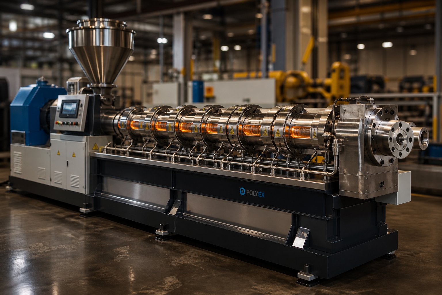
A plastic single screw extruder is a continuous processing machine that uses one rotating Archimedean screw inside a heated barrel to melt, homogenize, and pump thermoplastic polymers through a shaping die. Raw material — typically pellets, granules, or powder — enters through a hopper, travels along the screw through progressively hotter barrel zones, and exits as a uniform melt ready to become pipe, film, sheet, profile, or pellet.
Why does this relatively straightforward design account for the majority of extrusion installations worldwide? Three reasons stand out: mechanical simplicity, lower capital cost, and decades of proven reliability. A single screw extruder machine has fewer moving parts than its twin screw counterpart, which translates into easier operation, reduced maintenance, and a smaller footprint on the plant floor. While twin screw extruder price points can run two to three times higher for comparable throughput, a well-specified single screw system handles the bulk of thermoplastic shaping tasks — from polyethylene packaging film to PVC construction profiles — without the added complexity.
Core Components and Their Functions
Imagine following a single pellet from bag to finished product. Each component it encounters has a specific job:
- Feed hopper and feed throat — Gravity-feeds raw material into the barrel while a cooled throat prevents premature melting and pellet bridging.
- Barrel zones — A series of electrically heated (and sometimes cooled) sections that deliver precise conductive heat to the polymer as it advances.
- Screw — The heart of the single screw extruder. Its rotating flights convey, compress, and shear the material through feed, compression, and metering zones.
- Breaker plate and screen pack — A perforated steel plate backed by wire-mesh screens that filter contaminants, build back pressure, and convert rotational flow into linear flow.
- Adapter — Connects the barrel to the die, often housing melt-temperature and pressure sensors for process monitoring.
- Die — The final shaping tool that determines the extrudate's cross-section — annular for pipe, flat for sheet, circular for blown film.
Why This Machine Matters for Plastics Processing
Consider the range of products a single screw platform enables: drinking-water pipe safeguarding public health, stretch film protecting goods in transit, agricultural mulch film boosting crop yields, and cable insulation powering entire cities. Over 65% of all plastic products pass through an extruder at some stage of manufacturing, and the single screw design carries the lion's share of that volume. Its adaptability — swap the die and downstream equipment, and the same extruder can shift from sheet to profile production — makes it the workhorse of any plastics plant.
Yet many operators leave performance on the table simply because they lack a clear picture of what happens inside the barrel. The melting mechanisms, screw geometry choices, and processing parameter interactions that separate a good extrusion line from a great one deserve a closer look — starting with how plastic actually melts around that spinning screw.
How a Single Screw Extruder Melts and Conveys Plastic
Most operators assume that barrel heaters do the heavy lifting when it comes to melting polymer. It sounds logical — turn up the heat, melt the plastic. But that assumption is, as veteran extrusion engineer Jim Frankland puts it, "completely wrong." The reality is far more mechanical, and understanding how a screw extruder truly melts plastic is the single biggest unlock for improving output quality and throughput.
The Tadmor Melting Model Made Practical
Picture the barrel divided into three functional zones, each doing something fundamentally different to the polymer:
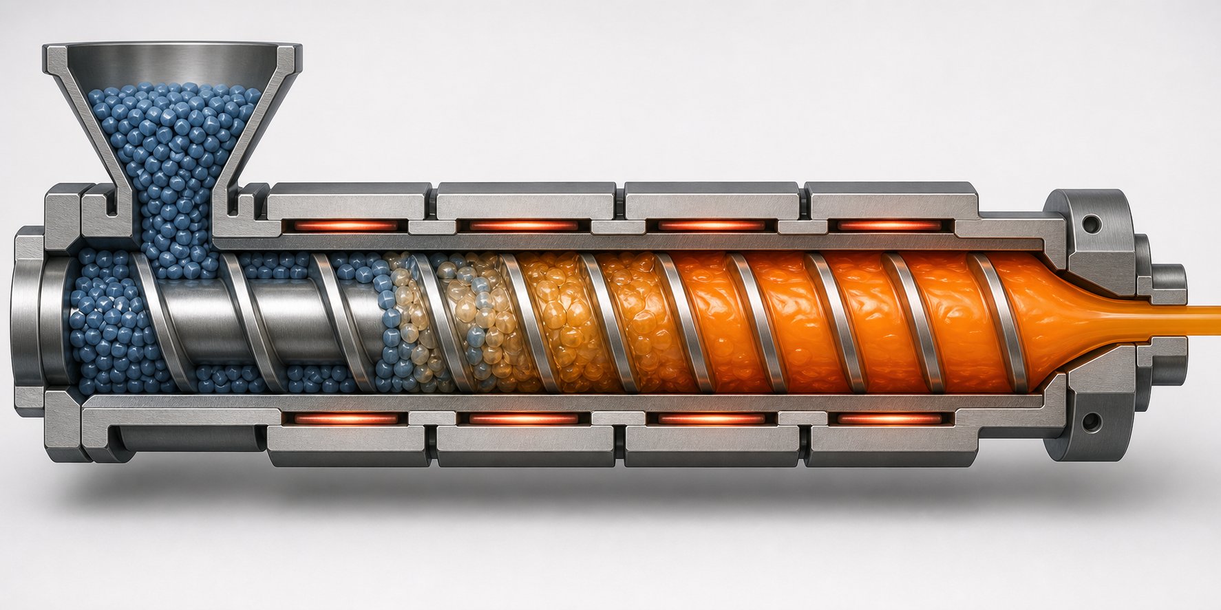
- Feed zone (solids conveying) — Pellets drop from the hopper into deep screw channels. The cooled feed throat keeps the material solid so it grips the barrel wall and is pushed forward by the angled screw flights. Think of it like a conveyor belt — the pellets compact into a solid "bed" and ride forward.
- Transition zone (compression/melting) — Here, the channel depth gradually decreases, squeezing the solid bed closer to the hot barrel wall. A thin melt film forms at the barrel surface — imagine a pat of butter pressed against a hot skillet. The rotating screw drags that thin molten layer toward the trailing flight, where it collects into a growing melt pool on one side of the channel. Meanwhile, the remaining solid bed gets narrower as more material melts off its surface.
- Metering zone (melt pumping) — By this point, the polymer should be fully molten. The shallow, constant-depth channel generates the pressure needed to push uniform melt through the screen pack and die at a consistent rate.
The key insight from the Tadmor model — the foundational framework developed by Zehev Tadmor in the 1960s and still used by screw designers — is that melting does not happen everywhere at once. It progresses along the barrel in a predictable wedge pattern. Cross-sections taken from Maddock solidification experiments clearly show the shrinking white solid bed and expanding dark melt pool as material advances downstream. About 80% of the melting occurs at the barrel wall interface, with the remainder at the edges of the solid bed near the screw root and flights.
Why Melting Efficiency Controls Output Quality
When melting goes well, you'll never notice it. When it doesn't, your product tells you immediately.
Incomplete melting allows solid polymer fragments — sometimes called gels or unmelts — to pass through the die. In blown film, these show up as visible specs or fisheyes that weaken the web and trigger customer complaints. In pipe extrusion, unmelted fragments create weak spots and inconsistent wall thickness. Heat-sensitive polymers like PVC face a different risk: excessive shear heating in the transition zone can cause localized degradation, discoloration, or even cross-linking before the material ever reaches the die.
The barrel wall — not the screw — initiates melting. The screw's rotation generates viscous shear in the thin melt film at the barrel surface, and that mechanical energy accounts for 85-90% of all heat entering the polymer during single screw extrusion. Barrel heaters contribute almost nothing once screw rotation begins.
This is why you'll often see barrel heaters in cooling mode during steady-state operation. The drive motor, not the heater bands, is the true engine of melting. Each revolution of the screw shears the viscous polymer layer, converting mechanical energy into thermal energy through friction. The specific heat of the resin and its viscosity at various temperatures during shearing determine how much energy each revolution delivers.
How Screw Speed and Barrel Temperature Interact with Melting
Here's where many processors get caught off-guard: doubling the screw speed does not double your melting capacity. Solids conveying and metering throughput scale linearly with RPM — double the speed, double the volumetric pumping. Melting flux, however, only increases by a factor of roughly 1.4 times. That mismatch means the solid bed gets pushed further downstream as screw speed rises, demanding more barrel surface area to complete the melt.
Imagine a traffic jam. The entry and exit lanes can handle more cars, but the middle bottleneck only widens slightly. Push too many cars through, and some exit without ever passing through the bottleneck. In screw extrusion terms, solid fragments discharge with the extrudate — exactly the defect shown in cross-sectional studies of HDPE pipe run above the melting capacity of the machine.
Raising barrel temperatures might seem like a fix, but its effect on actual melt temperature is surprisingly small. Conductive heat from heater bands only penetrates a thin layer near the barrel wall. The bulk of the polymer temperature rise comes from viscous dissipation — a function of screw speed, channel geometry, and polymer viscosity. In practice, a 20 degF increase in barrel zone setpoint might shift melt temperature by only 2-5 degF.
The real operating sweet spot lies in balancing screw speed against the screw's melting capacity. Every single screw extrusion line has a maximum rate at which the extrudate remains completely molten and free of solid fragments. Exceed that rate, and no amount of barrel heat adjustment will compensate. The only short-term fix is to reduce screw speed — but the long-term solution involves rethinking the screw geometry itself.
Screw Design Parameters That Control Extruder Performance
Screw geometry is the single largest lever you have over melt quality, throughput, and energy efficiency. Yet many processors run whatever extruder screw shipped with the machine years ago, never questioning whether its dimensions still match the resin or product they're producing today. Three core parameters — L/D ratio, compression ratio, and helix angle — define how an extrusion screw behaves. Understanding them gives you the vocabulary to evaluate performance problems and the confidence to specify a better replacement.
L/D Ratio and What It Tells You About Processing Capability
The length-to-diameter ratio (L/D) compares the screw's working length to its outer diameter. A 90 mm screw that is 2,700 mm long has a 30:1 L/D. Think of it as the runway available for melting, mixing, and pressure building — a longer runway gives the polymer more time and barrel surface contact to complete each task.
Common L/D values fall into three practical tiers:
- 24:1 — Adequate for pre-compounded pellets and simpler profiles where the resin melts easily and mixing demands are low.
- 30:1 — The most widely used general-purpose ratio, balancing melting capacity with manageable torque requirements for PE, PP, and PS processing.
- 36:1 — Chosen when extended melting or intensive mixing is needed — for example, processing powder blends, incorporating high levels of masterbatch, or running recycled feedstock with variable bulk density.
Longer L/D screws deliver more residence time and barrel contact area, which improves melt homogeneity. The trade-off? Higher torque demand on the drive motor, tighter manufacturing tolerances for the screw shaft, and — as GS Extruder's engineering analysis cautions — increased susceptibility to shaft deflection that can score the barrel bore. For thermally sensitive polymers like PVC, a shorter L/D is often preferred precisely because it limits residence time and reduces the risk of heat degradation.
Compression Ratio and Flight Depth Explained
Compression ratio is the relationship between the feed-zone channel depth and the metering-zone channel depth. If the feed channel is 9 mm deep and the metering channel is 3 mm deep, the compression ratio is 3:1. That ratio tells you how aggressively the screw squeezes the solid bed as it transitions into melt.
A higher compression ratio generates more shear and pressure — ideal for crystalline polymers like HDPE and nylon that need forceful compaction to melt efficiently. A lower ratio protects heat-sensitive or amorphous materials by reducing viscous heating. Selecting the wrong ratio for your resin is one of the fastest paths to either unmelt defects (too low) or thermal degradation (too high).
The table below compares typical compression ratios and feed-zone flight depths for common thermoplastics. These values represent widely used starting points; always confirm with your screw designer or manufacturer data for your specific application.
| Polymer | Typical Compression Ratio | Typical Feed Depth (relative) | Processing Notes |
|---|---|---|---|
| PE (HDPE/LDPE) | 3.0 – 4.0 | Deep | High compression needed for crystalline structure; tolerates aggressive shear |
| PP | 2.5 – 4.0 | Moderate to deep | Similar to PE; slightly lower ratio for random copolymers |
| Rigid PVC (pellet) | 2.0 – 3.0 | Moderate | Low ratio protects against thermal degradation; narrow processing window |
| Nylon (PA6, PA66) | 3.0 – 3.7 | Moderate to deep | Sharp melting point demands rapid compression; moisture sensitivity requires pre-drying or vented screws |
Notice the pattern: crystalline resins with a distinct melting point and high solid-to-melt density change — like HDPE and nylon — require higher compression ratios. Amorphous or thermally sensitive materials like PVC sit at the lower end. Getting this single extruder screw parameter wrong explains a surprising number of "mystery" quality problems on the plant floor.
Helix Angle and Flight Geometry
The helix angle is the angle between the screw flight and a plane perpendicular to the screw axis. For a standard square-pitch screw (where the pitch equals the diameter), this angle lands at approximately 17.66 degrees. It might sound like a minor geometric detail, but it directly governs how efficiently solids convey and how much pressure the screw can build.
A steeper helix angle (closer to 30 degrees) increases the channel volume and can boost throughput, but it reduces pressure-generating capability and shortens the effective residence time. A shallower angle does the opposite — more pressure, less volume per turn. Research published in screw parameter studies indicates that a 30-degree helix angle works best for powder feeds, while angles around 17 degrees suit cylindrical or spherical pellets — precisely because the tighter wrap gives pellets the barrel-wall friction they need to convey reliably.
In practice, you'll encounter screws where the pitch — and therefore the helix angle — varies along the length. A wider pitch in the feed zone improves solids intake for difficult-to-feed materials like regrind flake or low-bulk-density powders, while a tighter pitch in the metering zone maximizes pressure stability at the die. Variable-pitch designs add manufacturing cost, but they solve real feeding problems that a constant-pitch screw simply cannot address.
Flight width and the clearance between the flight land and barrel wall round out the geometry picture. Wider flights reduce channel volume but increase shear at the barrel surface — useful for dispersive mixing but detrimental to throughput. Flight clearance, typically held within 0.1 to 0.6 mm, controls leakage flow: too tight and you risk metal-to-metal contact from thermal expansion; too loose and melt flows backward over the flights, slashing pumping efficiency and overheating the resin through excess friction.
Every one of these dimensions — L/D, compression ratio, helix angle, flight width, and clearance — interacts with every other. Change one parameter and you shift the entire operating envelope of the extruder screw. That interdependence is exactly why modern screw engineering has moved beyond the basic three-zone design toward specialized geometries that isolate and optimize each function independently.
Advanced Screw Designs That Overcome Traditional Limitations
A conventional three-zone screw does one thing reasonably well for many polymers — but it has blind spots. Solid-bed breakup can send unmelt fragments downstream. Melt-temperature uniformity suffers because material near the barrel wall is hotter than material near the screw root. And distributive mixing of colors, additives, or regrind blends remains limited. These weaknesses once pushed processors toward costlier twin screw platforms for anything beyond straightforward extrusion. Modern screw extruders, however, have closed much of that gap through specialized flight geometries, mixing sections, and multi-stage configurations that address each weakness independently — all on a single screw plastic extruder platform.
Barrier Screws and How They Improve Melting Uniformity
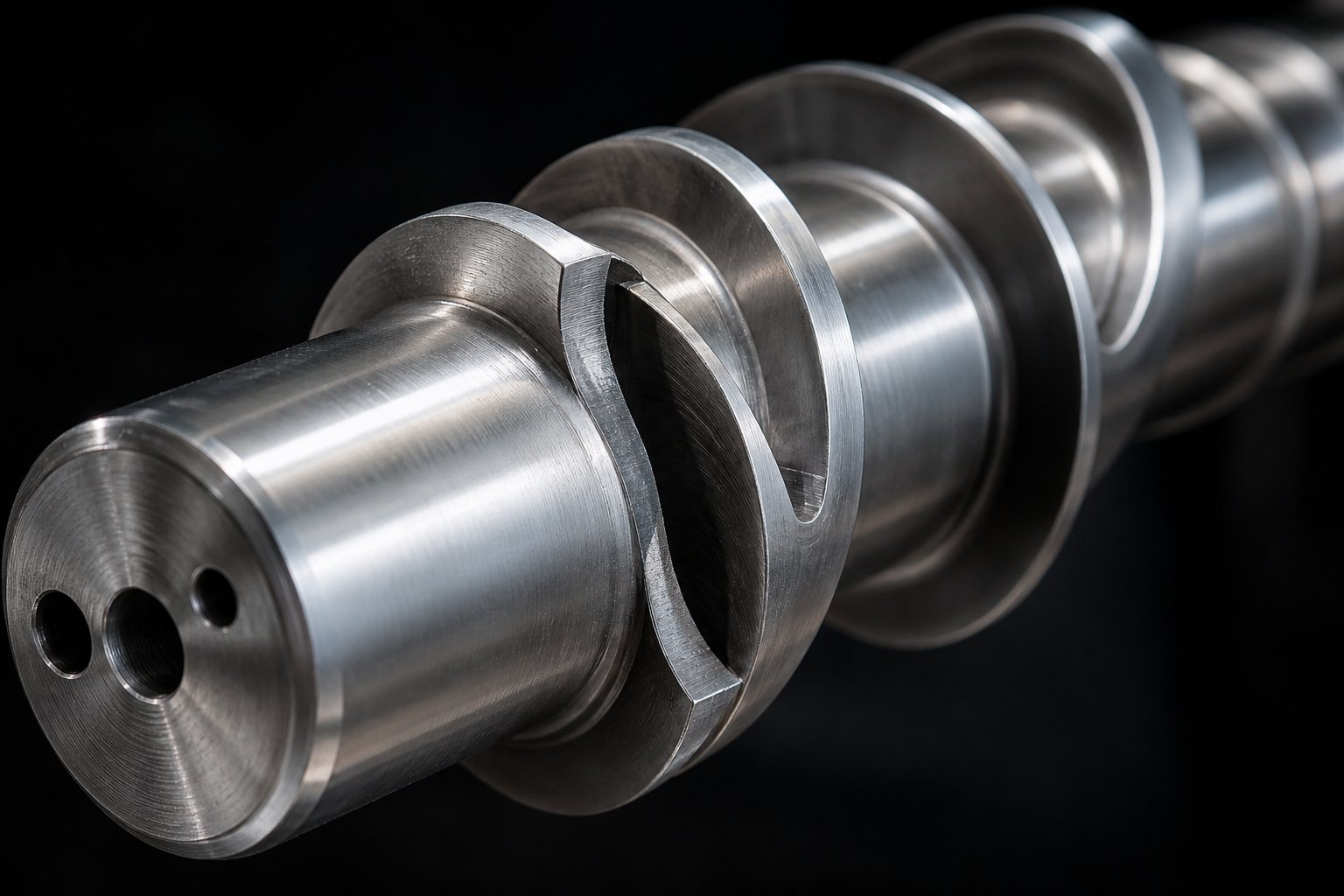
The biggest vulnerability of a conventional screw is solid-bed breakup. As the solid bed narrows during melting, it can fracture into smaller pieces that drift into the melt pool and ride through the metering zone unmelted. Barrier flight technology solves this by adding a secondary flight — the barrier flight — that physically separates the solid bed from the melt pool along much of the compression zone. The clearance over this barrier flight is tight enough to let only molten polymer pass through, while solids remain confined in a dedicated channel where barrel-wall contact continues to melt them.
Two principal barrier designs dominate the industry, each suited to different polymer characteristics:
Maillefer (crossing) barrier. One of the earliest barrier concepts, this design uses a barrier flight that crosses the main flight at an angle, gradually narrowing the solids channel while widening the melt channel. The solids channel experiences no sudden restriction at the barrier start, which makes this style particularly effective for hard or slippery polymers whose fragile solid beds resist abrupt cross-section changes. Extrusion authority Jim Frankland notes that crossing barriers also generate more head pressure because of their wider, shallower melt channel — an advantage when the die and downstream equipment impose significant flow resistance.
Barr (parallel) barrier. Developed later, the parallel barrier runs its secondary flight roughly parallel to the main flight, creating side-by-side solids and melt channels. The key advantage? For a given axial length, a parallel barrier design offers roughly one-third more surface area in the solids channel compared with a crossing barrier of the same screw diameter and pitch. Since melting capacity is largely proportional to the barrel-wall surface area available for solids melting, the parallel style delivers higher output with complete melting for polymers that have greater energy requirements — those with higher melting points, higher specific heats, or strong shear-thinning behavior, such as HDPE and nylon.
Variants of these two base designs abound. The Dray-Lawrence modification, for example, increases the helix angle within the barrier section to pack more channel volume into the same axial length, boosting throughput without significantly improving melting capacity per unit length. Designers also tailor the solids-channel exit — either closed (requiring nearly complete melting before the barrier ends) or open (relying on downstream mixing elements to finish the job). Getting this detail wrong leads to pressure surging, accelerated screw wear, or poor thermal homogeneity — problems often misattributed to barrel temperature settings when the root cause is barrier geometry.
Mixing Elements for Better Melt Homogeneity
Even a well-designed barrier screw can deliver melt that is thermally stratified or unevenly blended with colorants and additives. That's where dedicated mixing sections come in. Positioned after the barrier or metering zone, these elements apply two distinct mechanisms — dispersive and distributive mixing — in varying proportions depending on the design.
Imagine dispersive mixing as placing material between two plates and rotating one against the other. The narrow gap generates high shear stress that breaks apart pigment agglomerates, gels, and any remaining solid fragments. Distributive mixing, by contrast, works more like stirring batter with a spoon — repeatedly dividing, reorienting, and recombining flow streams until every region of the melt is compositionally identical.
Here are the most common mixer types found on single screw extrusion machines and when each one excels:
- Maddock (fluted) mixer — Primarily dispersive. Melt enters open inlet flutes and is forced over a narrow clearance land before exiting through adjacent outlet flutes. The high shear across that land acts as a dam, trapping unmelted particles and pigment clumps until they are reduced in size or fully melted. Best application: eliminating gels in film extrusion, dispersing color concentrates, and completing melting after an open-end barrier section.
- Saxton mixer — Primarily distributive. Multiple helical flights with varying leads divide and recombine melt streams many times with numerous reorientations. Shear stress is relatively low, so melt-temperature rise is minimal. Best application: blending regrind with virgin resin, homogenizing masterbatch letdowns, and processing heat-sensitive polymers like PVC where additional shear heating is undesirable.
- Egan (undercut-flight) mixer — Strong dispersive and distributive characteristics. All flights are undercut so melt passes over multiple high-shear zones while simultaneously experiencing leakage flow and repeated reorientation. Industry analysis describes this design as combining both mixing modes at high intensity. Best application: demanding color-matching applications and compounding runs where thorough blending must occur in a short screw length.
- Pineapple mixer — Distributive with moderate dispersive action. Diamond-shaped pins or staggered rows of faceted elements split melt into many small streams. Best application: blending multiple additives at low concentrations, such as UV stabilizers and slip agents in agricultural film formulations.
- Dulmage mixer — General-purpose mixing. A series of slotted rings that divide and recombine flow with moderate shear. Best application: all-around improvement in melt homogeneity where neither extreme dispersive nor distributive action is required.
No single mixer design fits all situations. As a practical rule, if your primary problem is unmelted particles, gels, or undispersed pigment, lean toward a Maddock. If temperature uniformity or additive distribution is the concern, a Saxton or pineapple section adds minimal heat while dramatically improving blend quality. Many high-performance screw extruders combine two mixer types in series — a dispersive section followed by a distributive one — to cover both bases.
Vented and Grooved Feed Screws for Specialized Processing
Two more innovations extend what a single screw extrusion machine can handle, each targeting a different bottleneck.
Two-stage vented screws are essential wherever moisture or volatile gases must be removed during processing. Hygroscopic resins like nylon absorb atmospheric moisture that causes bubbles, splay marks, and hydrolytic degradation if not extracted. Recycled feedstock often carries residual moisture, ink solvents, or other volatiles from its prior life. A vented screw addresses this by essentially stacking two screws end to end on the same shaft. The first stage melts and pressurizes the polymer normally. A deep-channeled decompression zone then drops melt pressure to atmospheric levels, exposing a large melt surface through a barrel vent port where steam and volatiles escape. The second stage re-pressurizes the degassed melt and pumps it to the die.
Proper vent-zone design is critical. As SpiraMelt Technologies' engineering team explains, if the second stage doesn't have enough pumping capacity relative to the first, molten polymer floods backward through the vent port — a messy, costly, and production-halting event. Incorporating multiple flights in the vent section helps separate melt into thin strands with more exposed surface area, significantly improving volatile removal efficiency over conventional deep single-channel vent designs. Three-stage screws with dual vent ports handle the most demanding degassing requirements, such as processing highly contaminated post-consumer regrind.
Grooved feed section technology takes a completely different approach to improving performance. Instead of modifying the screw, it modifies the barrel. Precision-machined longitudinal or helical grooves are cut into the feed throat's inner surface, dramatically increasing the friction between the polymer and the barrel wall. The result is positive, pressure-driven solids conveying that is largely independent of screw speed.
Why does that matter? On a smooth-bore barrel, throughput is governed by the friction balance between the polymer-barrel and polymer-screw interfaces — a balance that shifts unpredictably with temperature, pellet shape, and resin lot variations. Grooved feed sections lock in a consistent, high conveying rate. Processors gain higher throughput at a given screw speed, lower melt temperatures (because less screw speed is needed), and narrower output fluctuations. The trade-off is higher barrel-zone pressures and increased wear in the grooved section, which demands hardened or bimetallic barrel linings.
Together, barrier flights, mixing elements, vented configurations, and grooved feed sections represent a toolkit that keeps the single screw platform competitive against twin screw alternatives for all but the most shear-intensive compounding tasks. The real art lies in matching the right combination of these features to a specific polymer and end product — and that matching process is exactly what separates a productive line from one that chronically underperforms.
Application Matrix Matching Extruder Configurations to End Products
Selecting a barrier screw, a Maddock mixer, or a grooved feed section in isolation means little unless you know which combination your specific end product demands. A blown film line and a pipe extrusion line may both use HDPE, but they require fundamentally different screw geometries, die designs, and downstream equipment. The matrix below maps each major application category to its ideal industrial extruder machine configuration — giving you a practical reference you can bring straight to the plant floor.
Pipe and Profile Extrusion Configurations
Pipe production is one of the highest-volume applications for single screw extruders. A typical setup pairs a barrier screw with a 30:1 L/D ratio, an annular die sized to the target pipe diameter, and a downstream vacuum calibration tank that holds the still-soft tube against a sizing sleeve while cooling water solidifies the wall. Haul-off units pull the pipe at a constant speed, and a planetary cutter or saw makes clean, chip-free cuts to length.
Profile extrusion — think window frames, deck boards, and cable trunking — follows a similar screw specification but swaps the annular die for a precision profile die. Because profiles have complex, non-symmetrical cross-sections, downstream calibration plates are spaced closely to prevent warping or sagging as the extrudate cools. Cooling is often a combination of vacuum calibration immediately after the die and spray tanks further down the line. The screw itself still benefits from barrier flights and a dispersive mixer to ensure uniform melt delivery, since even minor temperature gradients show up as dimensional distortion in thin-walled profile sections.
Film and Sheet Extrusion Requirements
Film extrusion splits into two distinct processes, each with its own equipment footprint and quality demands.
Blown film pushes melt upward through an annular die, where an air ring inflates the tube into a bubble. Collapsing frames flatten the bubble, and nip rolls pull it at controlled speed to set both the lay-flat width and film gauge. Melt-temperature uniformity is critical here — even a 3-5 degF variation across the die circumference creates gauge bands that affect roll quality. Screws with 30:1 or 33:1 L/D and a Maddock mixing section after the barrier zone help eliminate thermal striping and ensure consistent bubble stability.
Cast film and sheet extrusion routes melt through a flat die (also called a coat-hanger die) onto polished chill rolls. The rapid quench on the roll surface produces films with excellent clarity and gloss — a property advantage that Oliver Healthcare Packaging's engineering team highlights as a direct result of faster cooling compared to blown film. Cast lines favor screws with strong distributive mixing to prevent streaking, and tight die-lip adjustment is essential for thickness uniformity across the web.
Pelletizing and Recycling Line Setups
Pelletizing lines convert compounded or recycled melt into uniform granules ready for downstream molding or re-extrusion. The extruder feeds a strand die (multiple small-diameter holes) or an underwater pelletizer, and the choice depends on throughput and pellet shape requirements. A screw extruder granulator setup for compounding typically uses a 33:1 or 36:1 L/D screw with intensive mixing sections to achieve thorough additive dispersion before the melt reaches the pelletizing head.
Recycling lines face a tougher challenge. Post-consumer and post-industrial regrind varies in contamination level, moisture content, and bulk density from one batch to the next. Vented (two-stage) screws are standard for degassing moisture and volatiles without a separate pre-drying step. Continuous or hydraulic screen changers sit between the barrel and die to remove paper fragments, metal particles, and cross-linked gels without stopping production. When evaluating a plastic extruder for sale aimed at recycling, verify that the machine supports vented-barrel configurations and can accommodate screen changers rated for the expected contaminant load.
Across all of these application categories, operators eventually face the same reality: screws and barrels wear, and output quality degrades. Sourcing replacement barrels and screws tailored to each application — whether pipe, film, or recycling — is essential for maintaining the tight tolerances these processes demand. NANHAIYA's single screw barrel solutions serve exactly this need, offering custom barrels matched by machine model, engineering drawing, worn sample, or measured dimensions so that processors in every application segment can restore peak performance without guesswork.
The summary table below consolidates the key specifications for each application, making it easy to compare configurations side by side. If you're evaluating a plastic extrusion machine for sale or budgeting around extruder machine price, these specifications help you ask the right questions before committing to a purchase.
| Application | Typical L/D Ratio | Screw Type | Die Type | Key Downstream Equipment |
|---|---|---|---|---|
| Pipe | 30:1 | Barrier screw with dispersive mixer | Annular die | Vacuum calibration tank, haul-off, planetary cutter |
| Blown Film | 30:1 – 33:1 | Barrier screw with Maddock mixer | Annular (spiral) die | Air ring, collapsing frame, nip rolls, winder |
| Cast Film / Sheet | 30:1 – 33:1 | Barrier screw with distributive mixer | Flat (coat-hanger) die | Chill rolls, thickness gauge, edge trim, winder or sheet stacker |
| Profile | 30:1 | Barrier screw with dispersive mixer | Profile die | Vacuum calibration plates, spray cooling tank, haul-off, cut-off saw |
| Pelletizing | 33:1 – 36:1 | Barrier screw with intensive mixing sections | Strand die or underwater pelletizer head | Water bath (strand), centrifugal dryer, classifier |
| Recycling | 33:1 – 36:1 | Two-stage vented screw with mixing section | Strand die or underwater pelletizer head | Screen changer, degassing vent, water bath, pelletizer |
Every row in that table represents a distinct set of demands on screw geometry, barrel metallurgy, and thermal management. Even within a single application — say, pipe — the optimal plastic extruder machine price and configuration shift depending on the polymer (PE vs. PVC), pipe diameter range, and required throughput. The specifications above give you a solid starting framework, but the real performance gains come from fine-tuning the processing parameters that govern melt quality on a day-to-day basis.
Processing Parameters and How to Optimize Them
Screw geometry and application-specific hardware lay the foundation, but it's the processing parameters you dial in every shift that determine whether your extruder for polymer production delivers consistent, defect-free output or fights you with surging, gels, and dimensional drift. Three parameter groups — barrel temperature profile, screw speed, and back pressure — interact constantly. Adjusting one without understanding the other two is how operators chase problems instead of solving them.
Barrel Temperature Profile Strategy
Setting zone temperatures isn't about picking a single number and spreading it across every barrel section. Each zone has a distinct job, and its setpoint should reflect that job relative to the polymer's thermal behavior.
Feed throat: Always cooled — typically between 20 degC and 60 degC for standard thermoplastics. A hot feed zone allows pellets to soften prematurely, coating the screw root and barrel wall with a sticky layer that blocks fresh material from entering. The result is bridging, erratic output, and sometimes a complete feed stoppage. As SHS Extrusion Training's barrel temperature guide emphasizes, the feed zone must keep material solid enough for the grooves or barrel friction to grip and convey it forward while still allowing trapped air to escape back through the hopper.
Zone 1 (compression onset): Set above the polymer's softening or crystalline melting point. The goal here is to maximize dissipation — the frictional heat generated by the screw working against the compacting solid bed. Setting Zone 1 too low starves the transition zone of energy; setting it too high reduces the friction differential between barrel and screw that drives solids conveying.
Mid-zones through die: For most polyolefins like PE and PP, a gradually ascending profile works best — each zone a few degrees higher than the last, converging on the target melt temperature at the die. PVC demands a flatter, more uniform profile because its narrow processing window punishes even modest temperature spikes with degradation. A polyester extruder line running PET, by contrast, benefits from a hump profile — temperatures rise to a peak in the mid-barrel to ensure complete crystalline melting, then drop slightly near the die to reduce drool and improve strand stability at the pelletizer.
One critical caution: the temperature your controller displays is not the actual melt temperature. Thermocouple placement in the barrel wall means the reading reflects barrel steel temperature, not the polymer flowing through the channel. Actual melt temperature is almost always higher than the setpoint during steady-state operation because viscous dissipation from screw rotation contributes the majority of thermal energy. Operators who rely solely on displayed zone temperatures without periodically checking melt temperature at the die with a handheld probe risk running blind.
Screw Speed, Throughput, and Their Relationship
Screw RPM is the most intuitive lever on the control panel — turn it up, get more output. That relationship holds, but only within a defined operating window. Push beyond it and melt quality collapses faster than throughput climbs.
Here's why. Throughput scales roughly linearly with screw speed: double the RPM, and the volumetric drag flow through the metering zone nearly doubles. But as discussed in the melting section earlier, the melting rate only increases by a factor of about 1.4 times. At some critical speed, the solid bed can no longer fully melt before reaching the metering zone, and unmelt fragments pass through the die.
Shear rate rises with RPM as well, generating more viscous heat. For shear-sensitive polymers, this means degradation, discoloration, or molecular-weight loss — problems that no downstream fix can reverse. Residence time simultaneously drops, giving additives and colorants less time to disperse. The operating window, then, is the RPM range where:
- Melting is complete (no solid fragments at the die)
- Melt temperature stays within the polymer's processing range
- Output stability remains acceptable (pressure fluctuations at the die below +/- 1-2%)
- Surface quality meets product specifications
Finding this window requires methodical testing — start at a moderate RPM, measure melt temperature and pressure stability, inspect product quality, and incrementally increase speed until any of those indicators deteriorate. That upper boundary is your machine's true capacity for the current screw, resin, and die combination. Operators evaluating plastic extrusion machine cost often focus on maximum rated RPM, but the usable RPM range matters far more for real-world productivity.
Back Pressure, Screen Packs, and Melt Quality
Between the screw tip and the die sits a series of flow restrictions — the breaker plate, screen pack, adapter, and die land — that collectively generate back pressure. This resistance forces melt to work harder to exit, and that extra work has a direct benefit: it improves melt homogeneity by eliminating rotational memory from the screw, forcing material through fine mesh screens that trap contaminants, and increasing the residence time in the metering zone where final temperature equalization occurs.
Process optimization research from Dynisco demonstrates that adding a melt pump downstream of the screen pack can stabilize discharge pressure to the point where product thickness variation drops by two to three times — but even without a gear pump, proper screen pack selection makes a measurable difference.
Screen packs are typically stacked in a coarse-fine-coarse arrangement (for example, 20/60/150/20 mesh) on the upstream face of the breaker plate. The fine center screen does the actual filtering, while the coarse outer layers provide structural support against the melt pressure pushing through. Finer mesh catches smaller contaminants and gels but generates higher pressure drop, which reduces throughput and increases melt temperature from additional shear at the screen surface.
Higher back pressure generally means better mixing and fewer surface defects — but it also means lower throughput and higher melt temperature. Every application has a sweet spot where melt quality meets production rate targets, and finding it is one of the most valuable skills a process engineer can develop.
When screens clog during a run, back pressure climbs gradually. Melt pressure transducers upstream and downstream of the screen pack let operators track this rise in real time. A sudden spike signals contamination breakthrough or screen rupture — both require immediate intervention. Continuous or hydraulic screen changers, discussed in the recycling application section, automate this process for high-contamination feedstocks, but even clean-resin lines benefit from monitoring pressure differential across the pack as a leading indicator of process drift.
Getting temperature, speed, and back pressure dialed in transforms a plastic single screw extruder from a source of constant adjustment into a predictable production platform. Yet even the best parameter settings gradually lose their effectiveness as the mechanical heart of the system — the screw flights and barrel bore — wears away under thousands of operating hours. Recognizing when that wear crosses the line from acceptable to performance-limiting is a skill that separates reactive maintenance from proactive uptime management.
Downstream Equipment and Complete Extrusion Line Integration
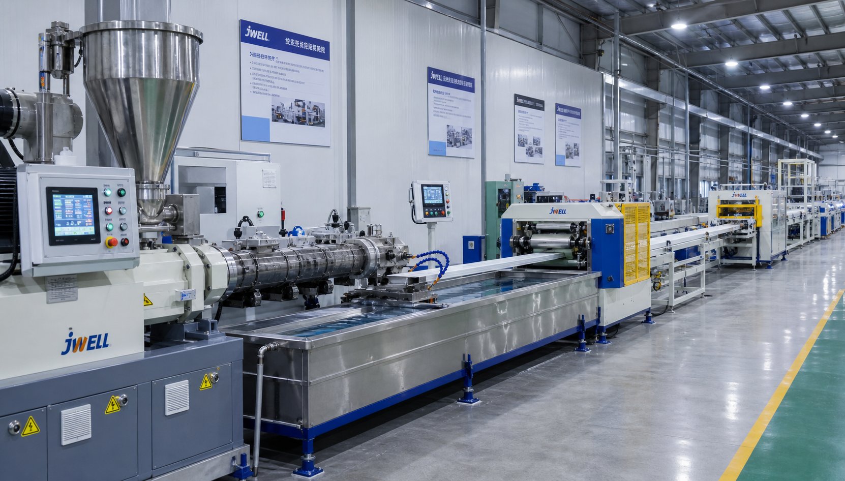
Your extruder can deliver flawless melt — perfect temperature uniformity, zero gels, rock-steady pressure — and your finished product can still fail dimensional specs. How? Because the extruder is only the first half of the production line. Everything that happens after the die — cooling, sizing, pulling, cutting — determines whether that beautiful melt becomes a saleable product or scrap. Many operators pour attention into screw design and barrel temperatures while treating downstream stations as afterthoughts. That imbalance is one of the most common and costly mistakes in plastics processing.
Cooling, Sizing, and Calibration Systems
When molten polymer exits the die, it already has the right cross-section — but it's soft, hot, and easily deformed by gravity, air currents, or uneven cooling. The downstream cooling and sizing equipment locks that shape in place before anything can distort it.
Each product type requires a different approach:
- Pipe extrusion — The hot tube enters a vacuum calibration tank immediately after the die. A slight vacuum pulls the soft pipe wall outward against a precision sizing sleeve while chilled water circulates around the exterior. This combination controls outside diameter, wall concentricity, and roundness. If vacuum is too low, the pipe shrinks undersized; too high, and it can stretch or develop surface drag marks.
- Blown film — An air ring directs a controlled stream of cooling air around the freshly extruded bubble. The frost line — the visible boundary where the bubble transitions from transparent melt to opaque solid — must remain stable and level. Collapsing frames then flatten the bubble into a lay-flat tube before nip rolls seal it for downstream slitting or winding.
- Cast film and sheet — Melt flows from the flat die directly onto polished, temperature-controlled chill rolls. Rapid quenching against the roll surface produces excellent clarity and surface gloss. Roll temperature, gap setting, and contact angle all influence crystallinity, residual stress, and final thickness.
- Profiles — Complex cross-sections pass through a series of calibration plates or blocks that cradle the shape while water spray or immersion baths extract heat. Because profiles have uneven wall thicknesses and asymmetric geometry, cooling must be balanced carefully to prevent warping or twist as different sections solidify at different rates.
One principle ties all of these systems together: downstream cooling capacity must match extruder output. If you increase screw speed by 15% without extending the cooling section or lowering coolant temperature, the product exits the line still carrying internal heat. It may look fine at the cutter — and then warp, bend, or go oval hours later on the pallet. As Jinxin's downstream equipment analysis points out, these are downstream problems that get misdiagnosed as extruder problems precisely because the defect doesn't appear until after packaging.
Pullers, Cutters, and Winders
The haul-off unit — also called the puller — is the speed reference for the entire line. It grips the solidified extrudate with caterpillar belts, rubber pads, or wheel assemblies and draws it through the cooling section at a precisely controlled velocity. That speed, relative to the extruder's volumetric output, sets the draw ratio and directly determines wall thickness or film gauge.
Imagine increasing haul-off speed by just 2% without touching the extruder. The product stretches slightly thinner — and if that drift goes unnoticed, hundreds of meters of out-of-spec material accumulate before anyone catches it. Conversely, a momentary slip in the puller pads causes a localized thick spot that can jam calibration tooling or fail dimensional inspection. Worn caterpillar pads, inconsistent clamping pressure, or a hunting servo drive are among the most frequent yet overlooked causes of thickness variation in extrusion lines.
End-of-line equipment converts the continuous extrudate into its final delivery form:
- Rotary or planetary cutters — Used for rigid pipe. The blade orbits around the pipe circumference, producing a clean, burr-free perpendicular cut without generating chips that could contaminate the next length.
- Guillotine or flying saws — Common for profiles and larger-diameter pipe. A flying saw travels with the product during the cut so the line never stops, maintaining continuous production.
- Winders — Film, flexible tubing, and small-diameter pipe are spooled onto cores. Winding tension must be carefully controlled — too much stretches or flattens the product; too little produces a loose, unstable roll that telescopes during shipping.
Whether you're running used extrusion equipment purchased from a secondary market or a brand-new turnkey line, the principle is identical: every downstream station must synchronize with the extruder. A mismatch at any point ripples through the entire process.
Process Control and Line Synchronization
A modern extrusion line isn't a collection of independent machines — it's a coordinated system governed by a centralized PLC that balances every variable in real time. According to PLC Programming IO's extrusion control guide, every variable interacts with every other: raise screw speed and melt pressure climbs; slow the haul-off and wall thickness drifts; let a barrel zone drop ten degrees and viscosity variation propagates all the way to the finished product.
Key instruments and control elements that tie the line together include:
- Gravimetric feeders — Measure and control the mass flow rate of resin and additives entering the hopper, compensating for bulk-density variations between virgin pellets and regrind.
- Melt-pressure transducers — Mounted at the die head, these provide both a safety interlock (tripping the drive if pressure exceeds safe limits) and a process diagnostic signal. Gradual pressure rise flags screen pack fouling; cyclical oscillation indicates screw surging.
- Ultrasonic or laser thickness gauges — Continuously measure product dimensions downstream and feed corrections back to the haul-off speed ratio, closing the loop on dimensional control without operator intervention.
- Centralized PLC with cascaded speed references — All downstream stations receive their speed as a ratio of a single master reference. When the operator adjusts the master speed, haul-off, cooling bath conveyors, and cutter automatically follow in proportion, keeping draw ratio and product dimensions locked.
Here's how all of these elements come together in a typical extrusion line, from raw material to packaged product:
- Material loading — Resin pellets and additives are conveyed from storage to the gravimetric feeder and hopper.
- Feeding and melting — The extruder's screw conveys, compresses, and melts the polymer along heated barrel zones.
- Filtering — Melt passes through the screen pack and breaker plate, removing contaminants and converting rotational flow to linear flow.
- Die shaping — The pressurized melt exits the die in the desired cross-sectional profile.
- Calibration and sizing — Vacuum tanks, sizing sleeves, or calibration plates lock in the product geometry while the extrudate is still soft.
- Cooling — Water baths, spray tanks, chill rolls, or air rings solidify the product and relieve internal stress.
- Haul-off — The puller draws the product at a controlled, synchronized speed that determines final dimensions.
- Dimensional measurement — Inline gauges verify thickness, diameter, or profile geometry and feed data back to the PLC.
- Cutting or winding — The continuous product is cut to length, coiled, or wound onto rolls.
- Packaging and palletizing — Finished product is labeled, stacked, or wrapped for shipment.
When shopping for extrusion equipment for sale — whether new or used extrusion equipment for sale on the secondary market — evaluate the line as a system, not a collection of parts. A high-performance extruder paired with an undersized cooling tank or an aging haul-off with worn drive belts will underperform a modestly spec'd extruder surrounded by well-matched, well-maintained downstream stations. Processors evaluating plastic extrusion machines for sale should request line-speed synchronization data and control architecture details alongside the extruder's throughput specs.
Even a perfectly synchronized line, however, eventually encounters problems that no amount of parameter adjustment can resolve. Surging output, surface defects, and declining throughput at constant settings all point toward process issues — or mechanical wear — that require a structured diagnostic approach rather than guesswork.
Troubleshooting Common Single Screw Extrusion Problems
You've optimized your temperature profile, matched your screw geometry to the resin, and synchronized every downstream station. Production runs smoothly for weeks — and then something shifts. Output drops 8% overnight. Surface defects appear on every third meter of pipe. Melt temperature creeps upward even though nothing changed on the control panel. These are the moments that separate operators who diagnose from operators who guess. A structured troubleshooting framework, grounded in the physics of how a plastic single screw extruder actually works, turns hours of trial-and-error into minutes of targeted corrective action.
Surging, Melt Fracture, and Output Inconsistency
Surging — the rhythmic rise and fall of extruder output at constant screw speed — is one of the most frustrating problems on any extrusion line. You'll see it as cyclical wall-thickness variation in pipe, gauge bands in film, or pulsating melt pressure readings on the die-head transducer. The oscillation period typically ranges from a few seconds to several minutes, and the root cause almost always traces back to one of four sources.
Solid-bed breakup is the most mechanically complex cause. When the narrowing solid bed in the compression zone fractures into fragments, chunks of unmelted polymer intermittently block and then release from the screw channel, creating pressure pulses that propagate to the die. Barrier screw designs (covered earlier) exist specifically to prevent this failure mode.
Inconsistent feeding produces a similar symptom but starts at the hopper. Bridging, ratholing, or erratic bulk-density variation in regrind blends starves the screw intermittently, dropping output before gravity refills the channel and throughput spikes back up.
Improper temperature in the solids conveying zone is, according to Dow fellow Mark A. Spalding's troubleshooting research, the single most common root cause of surging in smooth-bore extruders. The forwarding forces that push the solid bed forward depend heavily on barrel-wall surface temperature. If the feed casing overheats — because cooling-water channels have occluded with mineral deposits, for instance — friction conditions flip, and conveying becomes erratic. Spalding documents a case where an 8-inch two-stage extruder running polystyrene experienced severe surging with screw speed swinging between 100 and 160 RPM. The fix was straightforward: flush the feed casing cooling channels with an acidic solution and install a dedicated pump to restore adequate water flow.
Worn screw flights allow melt to leak backward over the flight lands during each revolution. As wear progresses, the leakage flow fluctuates with minor changes in melt viscosity or back pressure, introducing an oscillating component to the net forward flow.
Melt fracture is an entirely different beast. Rather than output variation, you'll see a rough, sharkskin-like surface texture on the extrudate — sometimes accompanied by a rhythmic ripple pattern. The cause is excessive shear stress at the die lips, where the melt velocity profile must abruptly rearrange as polymer exits the constrained die land into open air. Practical fixes include raising die-zone temperature to lower melt viscosity at the exit, widening the die gap to reduce wall shear rate, or adding a fluoropolymer processing aid that lubricates the polymer-metal interface and pushes the onset of melt fracture to higher throughput rates.
Die Drool, Gels, and Discoloration
Die drool — also called plate-out or die bleed — is the gradual accumulation of material on the die face at or near the exit. It looks harmless at first, just a waxy or crusty buildup at the lip edge. Left unchecked, it breaks off in chunks that embed in the extrudate, creating surface streaks, blocked passages in profiles, or stress concentrators in film that compromise mechanical integrity.
The underlying mechanism involves separation of compounded components. As ASACLEAN's extrusion engineering analysis explains, the abrupt pressure and velocity changes the resin undergoes at the die exit cause low-molecular-weight fractions, waxes, and incompatible additives to separate from the bulk melt. These separated components latch onto die surfaces in low-flow areas and accumulate over time. Severity increases exponentially with longer uninterrupted production runs.
Effective countermeasures span material, design, and operational strategies:
- Material adjustment — Work with your resin supplier to identify the incompatible component. Removing it, adding a compatibilizer, or altering the compounding procedure may eliminate the root cause entirely.
- Die design optimization — Increase land lengths to reduce the abruptness of the pressure drop at exit. Eliminate dead spots where separated materials can hang up. Apply low-friction coatings to die-lip surfaces.
- Operational management — Schedule brief, planned shutdowns for die-lip inspection and scraping before buildup reaches critical levels. Adjust die-zone temperatures in areas where drool accumulates. A periodic purge cycle can clear early-stage buildup without a full line shutdown.
Gels — those small, hard specks visible in film or transparent sheet — originate from two distinct sources. Unmelt gels are simply solid polymer fragments that survived the melting and mixing zones, often because screw speed exceeded the melting capacity or because the mixer section is worn. Cross-linked gels form when polymer degrades from excessive residence time or localized hot spots, creating insoluble particles that no amount of remelting will remove. Finer screen pack mesh (moving from 60 to 150 or even 200 mesh) catches smaller particles but increases back pressure. The more permanent solution is addressing the upstream cause — screw design, mixer condition, or temperature profile — rather than relying on screens as a filter.
Discoloration typically signals thermal degradation. Yellow or brown streaks in naturally colored product point to dead spots in the adapter, die, or screw where material stagnates and overheats. Black specks often indicate charred material flaking off a degraded screw surface or from stagnant pockets in the die. Systematic purging, polishing of flow surfaces, and verifying that the barrel temperature profile does not create unnecessary hot zones are the standard remediation steps.
Diagnosing Wear-Related Performance Decline
Every hour of operation removes a few microns of metal from screw flight lands and barrel bore surfaces. This wear is inevitable — and invisible until its effects show up in production data. As the clearance between flight OD and barrel ID increases beyond the original 0.05 - 0.10 mm per side, melt leaks backward over the flights during each screw revolution. That leakage flow reduces net pumping efficiency, forces operators to increase screw speed to maintain output, and generates additional shear heating that raises melt temperature without adding productive throughput.
The predictive maintenance data from MachineCDN quantifies the progression: when flight clearance reaches 0.15 - 0.25 mm per side, output at rated RPM typically drops to 85-95% of baseline. Beyond 0.25 mm, the decline accelerates — melt temperature runs 15 degF or more above setpoint, motor amperage climbs over 10% at constant RPM, and specific energy consumption (kWh per kg) swings unpredictably. A used extruder showing these symptoms isn't necessarily ready for the scrapyard, but its screw and barrel almost certainly need measurement and likely replacement.
For plants running used extruders or considering used single screw extruders, tracking these indirect wear indicators from the moment of installation builds a baseline that makes future degradation detectable months before it becomes critical. Even among used extruders for sale on the secondary market, the actual condition of the screw and barrel — not the machine's age or cosmetic appearance — determines its true production capability.
The diagnostic table below maps the most common performance symptoms to their probable root causes and recommended corrective actions, giving you a structured starting point instead of random parameter changes.
| Symptom | Probable Root Cause(s) | Recommended Corrective Action |
|---|---|---|
| Low output at rated screw RPM | Worn screw flights (excessive clearance); feed-zone temperature too high; screen pack blinding | Measure screw OD and barrel ID with micrometers and bore gauges; verify feed-throat cooling; check screen pack differential pressure |
| Poor surface finish (sharkskin, melt fracture) | Excessive die-lip shear stress; die land damage or buildup; melt temperature too low at die exit | Increase die-zone temperature; widen die gap; add processing aid; inspect and polish die lips |
| High melt temperature at constant settings | Worn screw increasing leakage flow and shear heating; heater zone overshooting; excessive back pressure from clogged screens | Pull screw and measure flight clearance; calibrate barrel thermocouples; replace screen pack and check loading rate |
| Dimensional variation (wall thickness, gauge bands) | Surging from solid-bed breakup or feed instability; worn puller pads; die-lip gap non-uniformity | Check feed-zone and feed-casing temperatures; inspect screw for wear in transition zone; verify haul-off clamping and die-gap settings |
| Increasing energy consumption (kWh/kg rising) | Screw-barrel wear forcing higher RPM to maintain output; degraded heater bands requiring longer duty cycles; drive efficiency loss | Compare specific output (kg/h per RPM) to baseline; inspect heater bands and contactors; check gearbox oil and drive motor condition |
| Gels or unmelt particles in product | Incomplete melting from excessive screw speed; worn mixer section; insufficient screen mesh fineness | Reduce screw speed to within melting-capacity window; inspect mixer clearances; increase screen pack mesh count |
Notice a pattern in the table: many symptoms share overlapping root causes, and wear is the thread running through nearly all of them. A single screw extruder doesn't fail suddenly — it degrades gradually, masking declining performance behind operator compensations like higher RPM, elevated temperatures, or more frequent screen changes. By the time the product itself shows defects visible to the naked eye, the screw and barrel may already be well past the point where measurement and replacement would have been the more economical path. That threshold — when to measure, when to refurbish, and when to replace — is exactly what separates reactive firefighting from a disciplined maintenance strategy.
Maintaining and Replacing Screws and Barrels for Peak Performance
The diagnostic table in the previous section reveals a hard truth: most chronic extrusion problems trace back to metal that is no longer where it should be. Screw flights lose their hard-faced edge, barrel bores oval out, and the precision clearances that once kept your plastic single screw extruder pumping efficiently widen by fractions of a millimeter per thousand operating hours. Those fractions compound silently until output, melt temperature, and energy consumption cross a threshold that even the most creative parameter adjustments can't recover. The question isn't whether your screw and barrel will need attention — it's whether you'll catch the decline early enough to plan the replacement or be forced into an emergency shutdown that costs far more.
Recognizing When Screws and Barrels Need Replacement
Wear doesn't announce itself with a warning alarm. It whispers through production data — and only if you're listening. Four measurable indicators, tracked consistently over time, give you an objective picture of component condition:
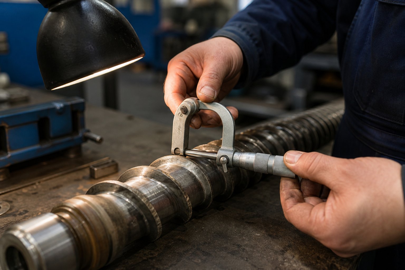
- Increased screw-barrel clearance — The most direct measurement. As Plastics Technology's wear analysis by Mark Spalding and Tim Womer explains, the flight clearance on a new screw is typically the nominal screw diameter divided by 1000 per side. For a 3.5-inch extruder, that means roughly 0.004 inches per side when new. Once clearance reaches two to four times that original value, pumping efficiency drops measurably. For critical-duty processes like medical tubing, replacement may be warranted at just 2x the original clearance, while less demanding applications like corrugated pipe can tolerate significantly more.
- Declining specific output — Specific output (kg/h per RPM) is the single most reliable trending metric. It strips away the masking effect of operators simply raising screw speed to compensate for lost efficiency. When specific output drops 10-15% below baseline, the screw is no longer delivering what it should — even if total throughput appears stable because RPM has been increased.
- Rising melt temperature at constant settings — As flight clearance increases, more melt leaks backward over the flights, gets sheared again, and picks up additional heat without contributing to forward flow. A 100 mm screw running 1 MI polyethylene at 150 kg/h, for example, can see discharge temperatures climb from 236 degC to over 246 degC as flight clearance increases from 0.005 to 0.016 inches per side — a temperature rise that can make blown film production impossible.
- Increased energy consumption — The drive motor works harder to push the same throughput through widened clearances. Motor amperage at constant RPM trends upward, and specific energy consumption (kWh/kg) rises even when output doesn't. These costs accumulate every shift, quietly eroding profitability.
Catching these trends early requires a disciplined measurement routine. Pull the screw during planned shutdowns and measure flight OD at multiple points along its length with a micrometer. Use a bore gauge to check the barrel ID at corresponding locations. Record the data, date it, and plot it against previous readings. This simple practice — taking fewer than 30 minutes — transforms maintenance from guesswork into forecasting. You'll know months in advance when replacement makes economic sense, giving you time to source components without emergency lead-time premiums.
A practical tip from veteran screw designers: always keep a spare screw in storage. When the current screw reaches end of service life, swap it immediately and send the worn one for refurbishment or replacement without losing production days. Just remember that a screw should generally not be refurbished more than three times — each re-welding of hard facing onto the base metal weakens the bond and increases the risk of delamination during operation.
Specifying Custom and Replacement Barrel Solutions
Sourcing a replacement barrel isn't as simple as ordering a commodity part by size. Every extrusion line — whether running a Davis Standard extruder, a Milacron extruder, or a machine from any of the dozens of single screw extruder manufacturers worldwide — has barrel specifications shaped by its specific gearbox interface, feed-throat geometry, heater band layout, and thermocouple port locations. A barrel that doesn't match these details precisely won't fit, or worse, it will fit poorly and introduce alignment-related wear that destroys your new screw within months.
Four sourcing pathways cover virtually every replacement scenario:
- By OEM machine model — The simplest approach. Provide the machine manufacturer, model number, and serial number, and the barrel supplier cross-references their database for exact dimensions. This works well for widely installed machines from major single screw extruder manufacturers but can stall for older, discontinued, or regionally specific models.
- By engineering drawing — If you have the original barrel drawing (or can obtain one from the OEM), a qualified supplier can manufacture to print. This guarantees dimensional accuracy and is the preferred path for critical-tolerance applications.
- By worn sample — When drawings aren't available and the machine model is obscure, shipping the worn barrel to the supplier for reverse engineering is a reliable fallback. The supplier measures all critical features — bore diameter, overall length, flange dimensions, port locations — and creates a manufacturing drawing from the physical part.
- By measured dimensions — In situations where the barrel can't be shipped (it's still installed in a running line, for example), taking precise field measurements and providing them to the supplier works as a final option. Bore gauge readings, external micrometer measurements, and photographs of flanges and ports give the manufacturer enough data to produce a replacement.
For operators who need application-specific barrel solutions across any of these sourcing scenarios, NANHAIYA's single screw barrel page serves as a practical resource — offering custom barrels matched by machine model, drawing, sample, or measured dimensions for pipe, film, sheet, pelletizing, and recycling lines.
Beyond dimensional accuracy, barrel material selection determines how long the replacement will last under your specific processing conditions. Two primary options dominate:
| Barrel Type | Surface Hardness | Best Suited For | Cost Consideration |
|---|---|---|---|
| Nitrided steel | 55 - 60 HRC | Standard polyolefins (PE, PP), PS, and unfilled resins with moderate wear demands | Lower initial cost; suitable replacement cycle for non-abrasive applications |
| Bimetallic lined | 60 - 70 HRC | Glass-filled resins, mineral-filled compounds, recycled feedstock with contaminants, corrosive polymers like PVC | Higher initial investment; significantly longer service life offsets cost in demanding applications |
The performance comparison data from Kaivanya Extrusion Technik confirms what plant experience consistently shows: bimetallic barrels with tungsten carbide or nickel-based alloy liners outlast nitrided barrels by roughly three times in abrasive applications, making them the economically sound choice despite the higher purchase price. For standard processing of unfilled polyolefins, however, nitrided barrels deliver adequate wear life at a fraction of the cost — a distinction worth understanding when budgeting for used extruder equipment that may need immediate barrel replacement upon installation.
Emerging Trends Extending Screw and Barrel Service Life
Material science and manufacturing technology continue to push wear life further, particularly in applications where abrasive or corrosive resins accelerate component degradation.
Advanced bimetallic alloys represent the most impactful development. As recycling volumes grow and processors handle increasingly contaminated post-consumer feedstock — often containing sand, glass fragments, paper fibers, and metallic inclusions — barrel liners formulated with higher concentrations of tungsten carbide particles in a nickel-boron matrix deliver measurably longer service intervals. Similarly, processing glass-filled nylon or mineral-reinforced PP at high throughput rates demands liner hardness and toughness that standard bimetallic compositions can't sustain. The latest alloy formulations balance extreme hardness (approaching 70 HRC) with enough ductility to resist cracking under the cyclic thermal stresses of startup and shutdown.
Improved nitriding processes are closing part of the gap for processors who don't need full bimetallic protection. Deeper case depths achieved through extended gas nitriding cycles and ion (plasma) nitriding techniques create a thicker hardened layer that resists through-wear longer than conventional nitrided surfaces. For Davis-Standard extruder operators running unfilled HDPE pipe, for instance, these improved nitrided barrels may extend replacement intervals by 30-40% compared to previous-generation treatments — a meaningful cost saving across a fleet of machines.
Energy-efficient high-speed screw designs take a different approach to the wear problem: they reduce it at the source. Optimized flight geometry — including refined helix angles, polished flight lands, and variable-pitch feed sections — lowers the contact forces between the screw and barrel wall during operation. Less metal-to-metal contact at the flight tips means slower wear progression, which extends the useful service life of both the screw and the barrel simultaneously. Some of these designs also deliver higher specific output, meaning the line achieves its target throughput at lower RPM — further reducing both wear rate and energy consumption per kilogram of product.
These trends share a common thread: they push the economics of screw and barrel replacement in the operator's favor. Whether you're maintaining a fleet of Milacron extruder lines, refurbishing a Davis Standard extruder acquired as used extruder equipment, or specifying new components for a greenfield installation, the combination of better alloys, deeper surface treatments, and smarter flight geometry means each replacement dollar buys more operating hours than it did even five years ago. Pairing that material progress with the disciplined measurement and trending practices described above creates a maintenance strategy where screw and barrel replacements become planned capital investments — not emergency expenses that catch your budget off guard.
Frequently Asked Questions About Plastic Single Screw Extruders
1. What is the difference between a single screw extruder and a twin screw extruder?
A single screw extruder uses one rotating Archimedean screw inside a heated barrel to melt and pump thermoplastics, while a twin screw extruder uses two intermeshing or co-rotating screws. Single screw systems dominate pipe, film, sheet, and profile production because of their mechanical simplicity, lower capital cost, and proven reliability. Twin screw extruders excel at intensive compounding and mixing tasks but typically cost two to three times more. Modern barrier screws, mixing elements, and grooved feed sections have closed much of the performance gap, keeping single screw platforms competitive for all but the most shear-intensive compounding work.
2. How does a single screw extruder melt plastic?
Contrary to common belief, barrel heaters contribute very little to actual melting during steady-state operation. The Tadmor melting model shows that roughly 85-90% of the thermal energy entering the polymer comes from viscous shear generated by screw rotation. A thin melt film forms at the barrel wall surface, and the rotating screw drags this molten layer toward the trailing flight where it collects into a growing melt pool. The solid bed progressively narrows as material advances through the compression zone. This is why barrel heaters often run in cooling mode during production — the drive motor, not the heater bands, is the primary energy source for melting.
3. What screw design parameters matter most for extruder performance?
Three core parameters define how an extrusion screw behaves. The L/D ratio (commonly 24:1, 30:1, or 36:1) determines residence time and melting capacity. The compression ratio — the feed-zone channel depth divided by the metering-zone channel depth — controls shear intensity and must match the polymer type: higher ratios (3.0-4.0) suit crystalline resins like HDPE, while lower ratios (2.0-3.0) protect heat-sensitive materials like PVC. The helix angle governs conveying efficiency and pressure generation. Beyond these basics, barrier flights, mixing elements such as Maddock or Saxton mixers, and grooved feed sections further optimize performance for specific applications.
4. How do I know when my extruder screw and barrel need replacement?
Four measurable indicators signal wear-related decline. First, increased screw-barrel clearance beyond two to four times the original specification (typically the screw diameter divided by 1000 per side). Second, declining specific output measured in kg/h per RPM — a drop of 10-15% from baseline warrants investigation. Third, rising melt temperature at constant barrel settings, caused by increased leakage flow and additional shear heating over worn flights. Fourth, increasing energy consumption (kWh/kg) as the motor works harder to maintain throughput. Regular measurement with bore gauges and screw micrometers during planned shutdowns enables early detection and planned replacement rather than emergency downtime.
5. What causes surging in a single screw extruder and how can it be fixed?
Surging — the cyclic rise and fall of output at constant screw speed — typically traces to one of four root causes. Solid-bed breakup in the compression zone sends intermittent chunks of unmelt downstream, creating pressure pulses. Inconsistent feeding from bridging or bulk-density variation starves the screw periodically. Overheated feed-casing cooling channels reduce barrel-wall friction and disrupt solids conveying — often the most common cause in smooth-bore machines. Worn screw flights allow fluctuating melt leakage backward over flight lands. Solutions range from installing barrier screw designs and restoring feed-zone cooling to measuring and replacing worn screws and barrels with components matched to the specific machine model and application.
Written by
Nanhaiya Technical Team
Zhoushan Nanhaiya Plastic Machinery Co., Ltd.
The Nanhaiya technical team supports screw and barrel manufacturing projects through application review, technical communication, custom manufacturing coordination, and production and quality control.
Discuss Your Application
Related Articles
More insights on screw barrel technology and plastics processing.

What Nobody Tells You About Screw Barrel For Plastic Machine Design
Oct 10, 2026
Learn how screw barrel for plastic machine design affects melt quality, throughput, and wear life. Covers geometry, resin matching, troubleshooting, and sourcing.
Read Article
Single Screw Extruder for Sheet: Stop Guessing, Start Specifying
Oct 9, 2026
Learn how to specify a single screw extruder for sheet production. Covers screw geometry, resin-specific processing, troubleshooting, and maintenance best practices.
Read Article
PE Pipe Extruder Machine: What Datasheets Won't Tell You
Oct 9, 2026
Learn how a PE pipe extruder machine works, key specs explained, material grade selection, maintenance tips, and buyer guidance beyond the datasheet.
Read ArticleLooking for something else?
Search by material, symptom or product and jump straight to the relevant page.
These are navigation suggestions based on keyword matching — not a quotation, not a delivery commitment, and not a substitute for engineering review. Final specification is confirmed by our engineers against your drawings and processed material.
Need help with screw barrel selection?
Share your machine model, processed material and application. Our team can help with pricing and technical support.