

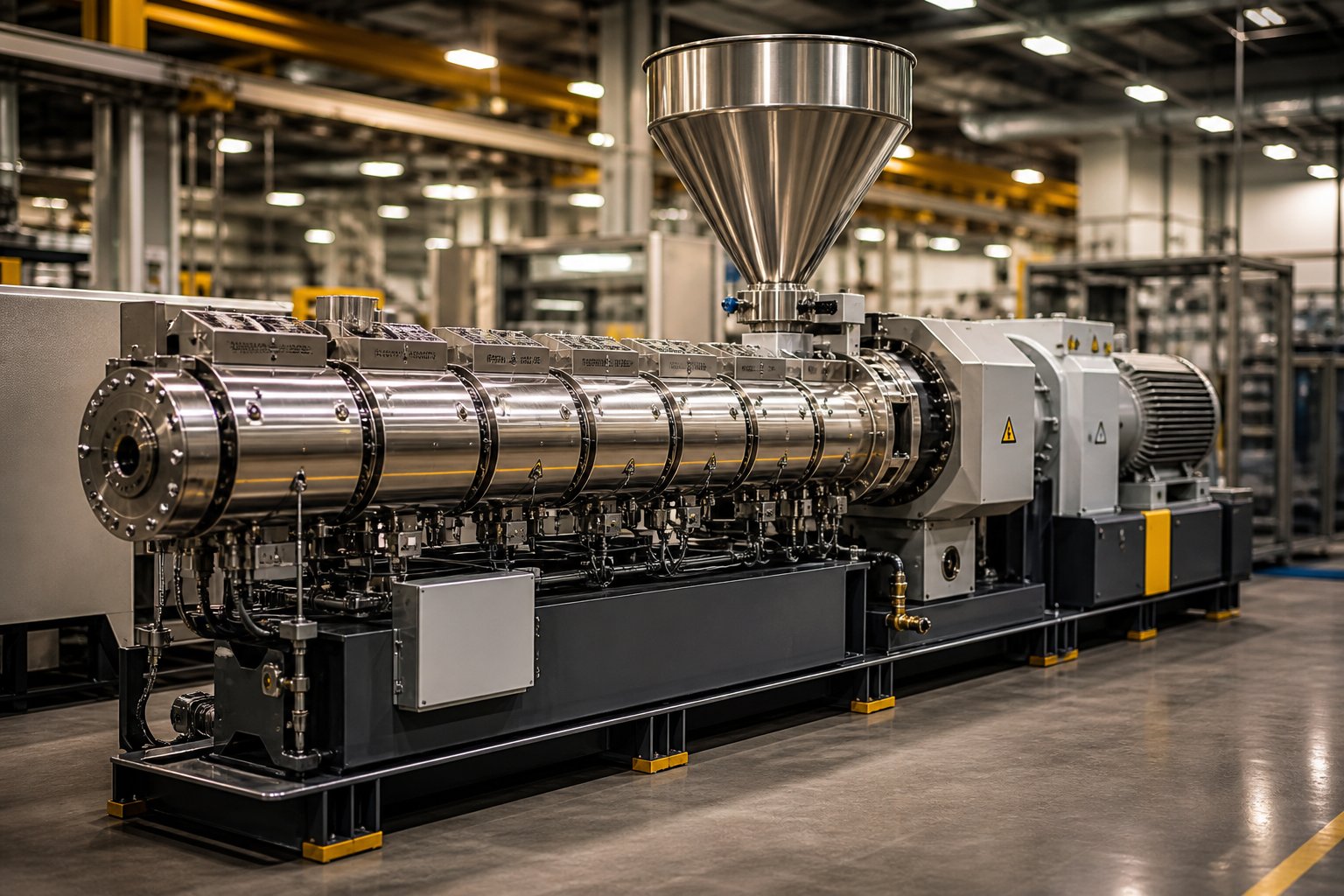
What Is a Plastic Screw Extruder and Why It Matters
When your extrusion line starts producing inconsistent wall thickness, surface defects, or unexplained throughput drops, the root cause almost always traces back to one component: the screw. Yet many plant operators and procurement teams treat the extruder as a black box, relying on OEM defaults without understanding the mechanics driving their output. That disconnect costs real money in scrap, downtime, and missed production targets.
What a Plastic Screw Extruder Actually Does
A plastic screw extruder is a machine that uses one or more rotating screws inside a heated barrel to convey, compress, melt, and meter polymer material, then continuously push that molten plastic through a shaped die to form a desired cross-section. It functions as both a pump and a processor. The rotating screw generates mechanical energy through friction and shear, while barrel heaters supply thermal energy. Together, these forces transform solid pellets, powder, or flake into a homogeneous melt delivered at controlled pressure and temperature. This makes the screw extruder fundamental to producing pipes, profiles, films, sheets, pellets, and virtually every continuous plastic product on the market.
Why Screw Extruder Knowledge Matters for Your Operation
Imagine selecting a screw plastic extruder based solely on its rated throughput, only to discover weeks later that its compression ratio is wrong for your resin. The result? Poor melt quality, degraded material, and a production line that never hits spec. Equipment selection errors, screw design mismatches, and maintenance neglect are among the most common — and most preventable — causes of underperformance in extrusion plants.
The screw is the heart of every extrusion line — its geometry, condition, and compatibility with your resin determine throughput, melt quality, and part consistency.
This article is built as a process-engineer-oriented resource that bridges the gap between manufacturer marketing claims and academic polymer processing theory. Whether you're a floor operator troubleshooting melt surging, an engineer specifying a new line, or a procurement lead evaluating screw extruder suppliers, you'll find practical, decision-ready information here. The coverage spans the complete picture:
- Working principles — how material moves through the feed, compression, and metering zones
- Screw geometry — flight depth, compression ratio, L/D ratio, and modular element types
- Extruder type comparison — single-screw, co-rotating twin-screw, counter-rotating twin-screw, and specialty configurations
- Material matching — resin-specific screw design and processing guidance for PE, PP, PVC, ABS, PET, and Nylon
- Process parameters — screw speed, temperature profiles, back pressure, and downstream equipment
- Maintenance strategy — wear mechanisms, inspection methods, and refurbishment vs. replacement decisions
- Troubleshooting — a problem-cause-solution reference for common extrusion defects
- Selection guidance — a step-by-step decision framework for choosing the right extruder
Every section is designed to give you actionable knowledge — the kind that turns an underperforming extruder into a consistently reliable production asset. And it all starts with understanding exactly what happens to your resin from the moment it drops into the feed throat.
How a Screw Extruder Works From Feed to Die
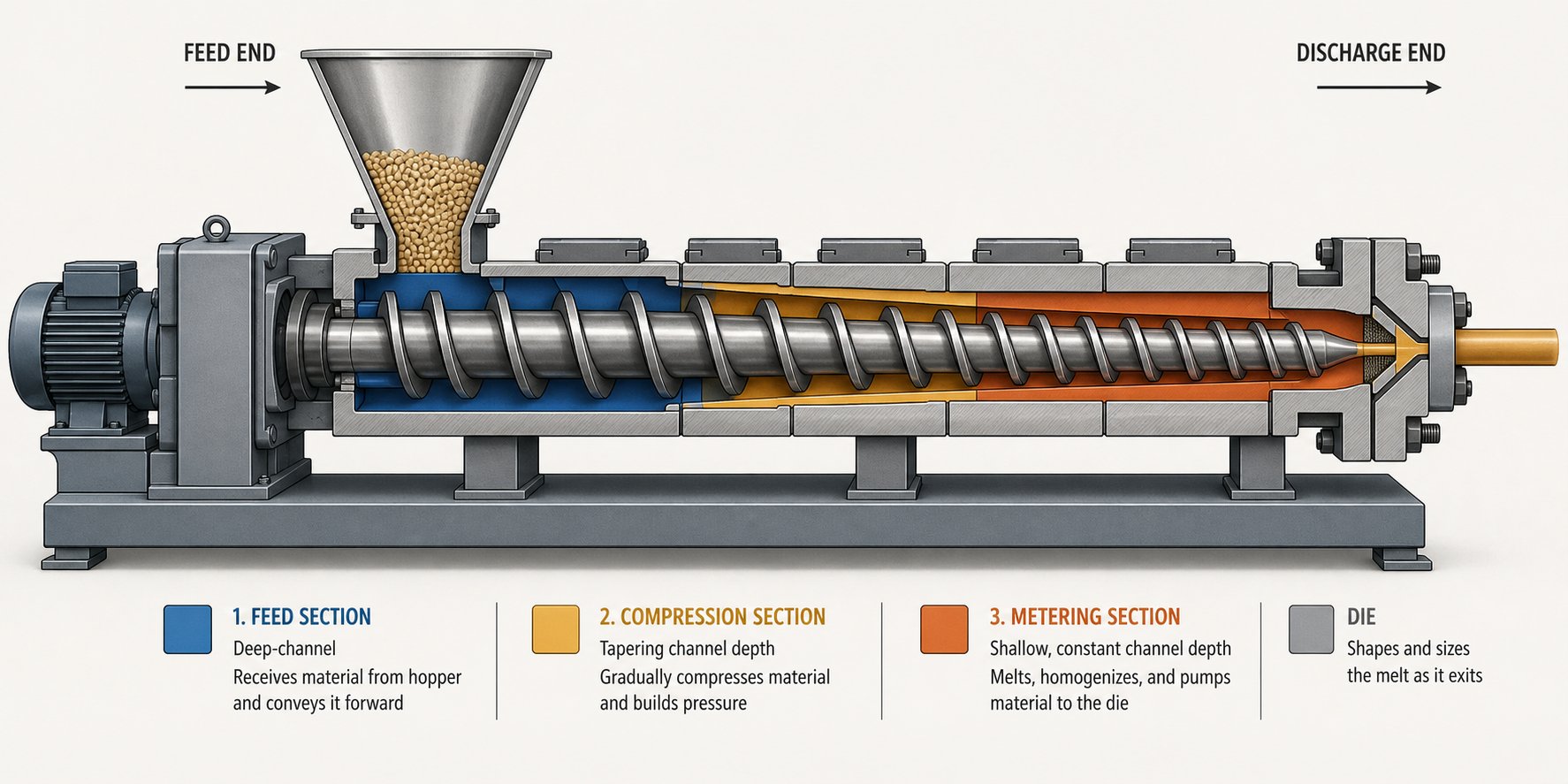
Drop a handful of plastic pellets into the feed throat of your extruder, and within seconds they begin a tightly orchestrated journey through three distinct functional zones. Each zone applies a different combination of mechanical and thermal energy to transform those rigid granules into a uniform, pressurized melt stream ready for the die. Sounds straightforward? In practice, the balance between these zones determines whether your line produces spec-quality product or fights surging, gels, and dimensional drift all shift long.
The three zones — feed, transition (compression), and metering — are not arbitrary labels. They correspond to measurable changes in the screw barrel geometry, specifically the depth of the channel between screw flights. That changing channel depth is what controls how aggressively the polymer is conveyed, compressed, sheared, and finally homogenized. Understanding what happens in each zone gives you a direct line of sight into why your process behaves the way it does.
Feed Zone and the Role of the Extruder Feed Barrel
The feed zone is where solid pellets or powder enter through the hopper and first contact the screw. Here, the screw channel is at its deepest, creating maximum volume to accept incoming material. The primary job of this section is not to melt anything — it is to convey solids forward as efficiently and consistently as possible.
How does that conveying actually work? Picture the pellets sitting in the deep channel between two screw flights. As the screw rotates, the material needs to move forward rather than simply spinning in place. That forward motion depends on a critical friction relationship: the friction between the pellets and the extruder barrel wall must be higher than the friction between the pellets and the screw root. When the barrel surface grips the material more effectively than the screw does, the solids slide forward along the helical channel. If this friction balance reverses — for instance, because the barrel is too hot at the feed throat and pellets begin to stick to the screw — conveying collapses, and output drops immediately.
This is exactly why keeping the feed throat cool is essential. If resin melts prematurely beneath the hopper, it coats the screw surface, kills the friction differential, and chokes material intake. Dedicated cooling jackets around the feed section prevent this.
For polyolefins like HDPE and PP, grooved feed barrels take conveying performance even further. Longitudinal grooves machined into the barrel bore in the feed section physically lock pellets against the barrel wall, dramatically increasing the frictional grip on solids. Case studies comparing groove-feed to smoothbore extruders have demonstrated that a smaller-diameter groove-feed machine can match or exceed the output of a larger smoothbore unit — while running at a lower melt temperature and consuming less energy. The trade-off is higher internal pressure in the feed zone, which demands a more robust barrel extruder design and careful screw geometry coordination downstream.
Transition Zone Where Compression and Melting Occur
As material advances beyond the feed section, it enters the transition — or compression — zone. You'll notice one defining geometric change here: the screw channel depth decreases progressively. This shrinking channel forces the loosely packed solids into an increasingly confined space, and that compression is where the real transformation begins.
Two heat sources drive melting in this zone. First, barrel heaters conduct thermal energy through the extruder barrel wall and into the polymer bed, forming a thin melt film on the barrel surface. Second — and more importantly — mechanical shear generates substantial frictional heat as the compacting solid bed is forced against the barrel wall by the decreasing channel depth. In most extrusion processes, this shear-generated energy actually contributes more to melting than the barrel heaters do. The heaters set the thermal boundary, but the screw's mechanical work does the heavy lifting.
The aggressiveness of this compression is captured by a single parameter: the compression ratio, defined as the ratio of the feed zone channel depth to the metering zone channel depth. A higher compression ratio means the channel narrows more dramatically, generating greater shear and pressure. Crystalline polyolefins like PE and PP tolerate — and benefit from — higher compression ratios because they need significant energy input to break through their crystalline melt point. Heat-sensitive amorphous resins like PVC, on the other hand, require gentle, gradual compression to avoid thermal degradation. Choosing the wrong compression ratio for your resin is one of the fastest paths to melt defects.
Metering Zone and Melt Uniformity
By the time material reaches the metering zone, it should be fully molten. This final section features a shallow, constant-depth channel — the shallowest point on the screw — designed to accomplish two things: homogenize the melt and build stable pressure to push material through the die.
The constant channel depth eliminates the aggressive compression and high shear rates of the transition zone. Instead, it provides a controlled environment where any remaining temperature gradients within the melt stream are evened out. Think of it as the conditioning stage: the polymer is no longer being transformed but refined. The metering zone length directly affects how uniform the melt temperature and pressure are at the die. A longer metering section gives the polymer more residence time for thermal equilibration and pressure stabilization, which translates into steadier output dimensions and smoother surface finish. Too short a metering zone, and you'll see pressure fluctuations at the die that manifest as surging, weight variation, or dimensional inconsistency.
The metering zone also functions as the extruder's pump. Its shallow channel creates the pressure needed to overcome resistance from screen packs, breaker plates, and the die itself. The balance between the screw's pressure-generating capacity and the system's downstream resistance is what ultimately determines your volumetric flow rate.
Zone-by-Zone Summary
- Feed Zone — Function: Solids intake and forward conveying. Screw geometry: Deep, constant-depth channel with wide flights. Key process outcome: Consistent, stable feed rate that prevents downstream surging and output variation.
- Transition (Compression) Zone — Function: Compaction, shearing, and melting of the solid bed. Screw geometry: Progressively decreasing channel depth. Key process outcome: Complete melting driven by the combined effect of barrel conduction and shear heating, governed by the compression ratio.
- Metering Zone — Function: Melt homogenization and pressure generation for die delivery. Screw geometry: Shallow, constant-depth channel. Key process outcome: Uniform melt temperature, stable pressure, and consistent volumetric output through the die.
Each zone depends on the one before it. If the feed zone delivers inconsistent solids, the compression zone cannot melt uniformly. If compression is too aggressive or too gentle for the resin, the metering zone receives a poorly conditioned melt that no amount of downstream adjustment can fix. This cascading dependency is why screw geometry — the precise dimensions of each zone — matters so much to your final product quality.
Screw Geometry Fundamentals That Control Performance
The cascading zone dependency described above raises an obvious follow-up question: what exactly defines each zone's behavior? The answer lives in screw geometry — a handful of measurable dimensions that dictate how aggressively your plastic screw extruder conveys, compresses, shears, and pumps polymer. Change one parameter by even a few millimeters, and you shift the entire melt profile. Yet most operators never see these numbers quantified or explained in practical terms. Here is the engineer-level breakdown.
Flight Depth, Pitch, and Helix Angle Explained
Every extruder screw can be described by three foundational geometric features that interact to control material flow.
Flight depth is the radial distance from the screw root (the solid core of the shaft) to the top of the flight (the helical ridge). It defines the channel volume available to hold and transport polymer. A deeper channel means more material per revolution but lower shear rate, because the polymer farther from the barrel wall experiences less velocity differential. A shallower channel — like in the metering zone — increases shear rate and reduces throughput per turn, which is exactly why the metering section homogenizes the melt so effectively.
Pitch refers to the axial distance between two consecutive flights, essentially one full wrap of the helix measured along the screw's length. A wider pitch moves material forward faster per revolution, increasing conveying rate. A tighter pitch slows axial transport but can improve mixing by keeping the polymer in the channel longer. Most standard plastic extrusion screw designs use a square pitch, meaning the pitch equals the screw's outside diameter. Deviating from this standard is common in specialty applications where conveying rate or residence time needs fine-tuning.
Helix angle is the angle of the flight relative to a plane perpendicular to the screw axis. It is geometrically linked to pitch and diameter: a larger helix angle corresponds to a wider pitch. In practical terms, adjusting the helix angle changes how efficiently the screw drags material forward versus how much cross-channel mixing occurs. Lower helix angles promote more shear and longer residence time, which can improve mixing but risk overheating heat-sensitive polymers.
Tying all three together is one of the most commonly referenced specifications in extrusion: the L/D ratio, or length-to-diameter ratio. This value describes how long the screw is relative to its bore diameter. A 90 mm screw with a 2,160 mm flighted length has a 24:1 L/D. Why does this matter? A longer L/D gives the plastic extruder screw more working length to complete melting, mixing, and pressure building. Common ranges fall between 24:1 and 36:1. Shorter ratios like 24:1 suit simple, single-resin extrusion of pre-compounded materials where melting demands are modest. Longer ratios — 30:1 to 36:1 — are typical for applications requiring enhanced mixing, higher throughput at lower screw speeds, or two-stage vented designs where part of the screw length is dedicated to devolatilization. Choosing the wrong L/D for your process is like selecting a gear ratio that never lets your engine reach its power band: everything works harder than it should, and output suffers.
Compression Ratio and Its Effect on Melt Quality
You encountered the compression ratio concept in the zone discussion. Here, it deserves a closer look because it is arguably the single most consequential design decision in any extrusion screw specification.
Compression ratio is calculated by dividing the feed zone channel depth by the metering zone channel depth. A screw with a 9 mm feed depth and a 3 mm metering depth has a 3:1 compression ratio. That number tells you how aggressively the polymer is squeezed as it travels from one end to the other — and it must match the resin's thermal behavior.
Low-compression screws (roughly 2:1 to 2.5:1) are designed for heat-sensitive materials like PVC. These resins degrade rapidly under excessive shear, so the channel narrows gradually, generating less frictional heat and applying gentler compressive force. The trade-off is that melting relies more heavily on barrel heaters and longer residence time, which is why PVC screws often run at higher L/D ratios.
Medium-compression screws (around 2.5:1 to 3:1) work well for amorphous resins such as ABS and PS that need moderate shear input without the risk of thermal degradation.
High-compression screws (3:1 to 4:1) suit semi-crystalline polyolefins like PE and PP. These materials require substantial energy input to overcome their defined crystalline melting point, and the aggressive channel-depth reduction delivers the necessary shear heating efficiently.
Keep in mind that these ranges are general guidelines. Your resin supplier's datasheet and your own process validation should always guide the final specification. Running a high-compression screw on a low-shear resin will overheat and degrade the polymer. Running a low-compression screw on a crystalline material will send unmelted particles straight to your die.
Screw Element Types for Modular Configurations
Everything discussed so far applies primarily to single-piece extrusion screw designs, where feed, transition, and metering zones are machined into one continuous shaft. Modular twin-screw extruders take a fundamentally different approach. Instead of a fixed geometry, they use interchangeable screw elements that slide onto splined shafts, allowing engineers to build custom screw profiles tailored to specific processes.
Imagine being able to rearrange your screw's personality — more mixing here, gentler conveying there, an aggressive kneading section right where your filler needs to be dispersed. That is exactly what modular elements enable. The main types include:
- Conveying elements — These are helical flight segments similar to a standard screw. Their primary function is to transport material forward through the barrel. Varying the pitch adjusts the conveying rate: wider pitch for fast transport in the feed section, tighter pitch for slower, more controlled movement downstream.
- Kneading blocks — Made up of individual disc-shaped lobes staggered at specific angles (commonly 30, 60, or 90 degrees), kneading blocks generate intense shear and elongational flow. They are the primary melting and mixing workhorses in a twin-screw configuration. The stagger angle determines aggressiveness: a 30-degree forward stagger provides moderate mixing with continued forward conveyance, while a 90-degree neutral stagger maximizes shear and residence time at that point.
- Distributive mixing elements — These elements split and recombine the melt stream repeatedly without applying high shear stress. They are ideal for blending color concentrates, liquid additives, or low-viscosity components uniformly throughout the polymer matrix without risking degradation.
- Dispersive mixing elements — Designed to break down agglomerates, gels, or filler clusters by forcing material through narrow high-shear gaps. They apply higher stress than distributive elements and are critical when processing pigment masterbatches or nano-fillers that tend to clump.
- Reverse (left-handed) elements — These flight segments are oriented opposite to the main conveying direction, creating a local dam or seal that increases pressure and residence time upstream. They are used to build melt seals for venting zones, ensuring volatiles and moisture can escape through vacuum ports without material leaking out.
The ability to combine these elements in virtually unlimited configurations is what makes modular twin-screw platforms so versatile for compounding, reactive extrusion, and devolatilization tasks. A single machine can be reconfigured for an entirely different resin system by swapping a few elements along the screw shaft — no new screw purchase required.
Geometry alone, however, only tells half the story. The same screw profile performs very differently in a single-screw machine versus a co-rotating or counter-rotating twin-screw system. The extruder architecture surrounding the screw changes everything about how those geometric features translate into real-world processing performance.
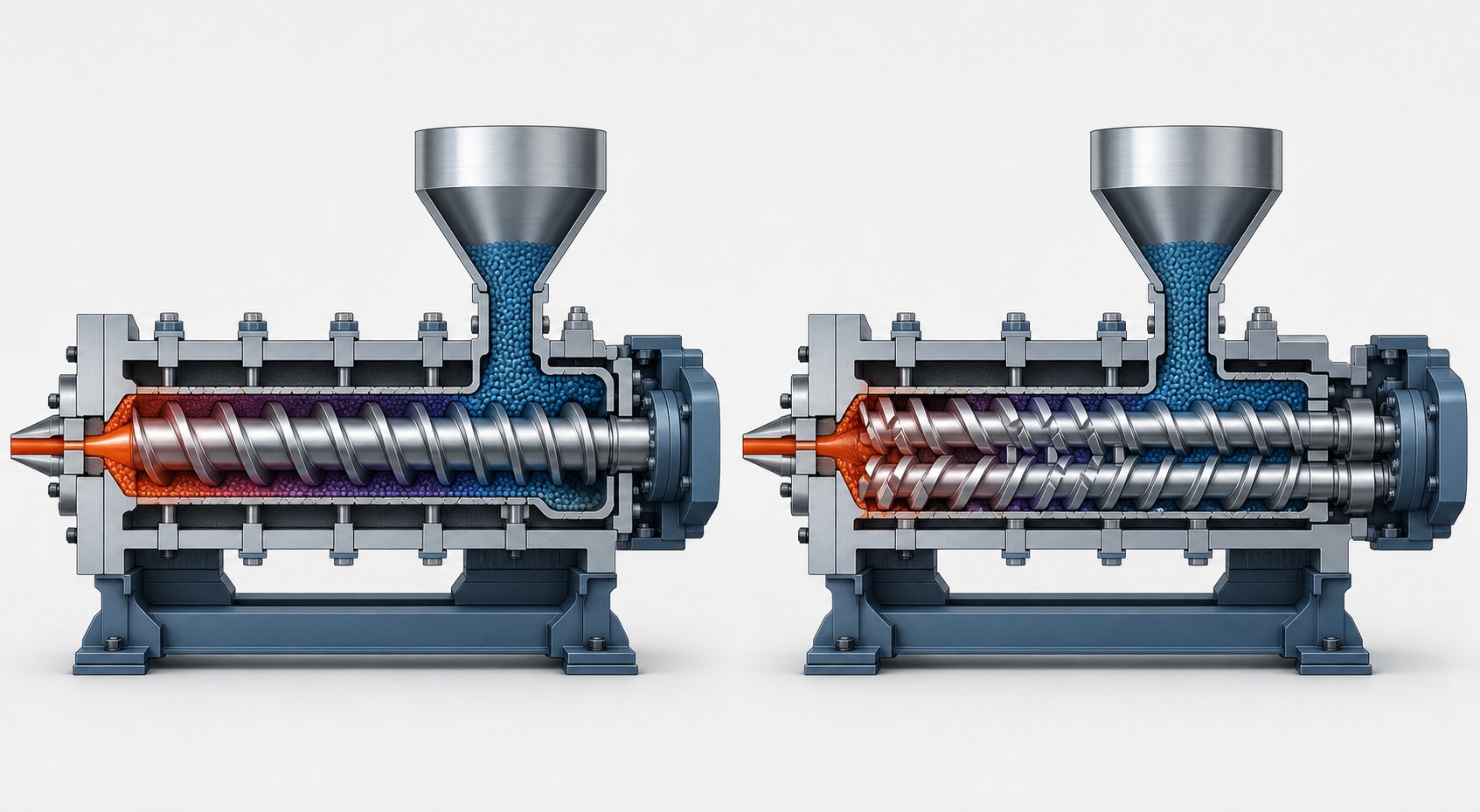
Single Screw vs Twin Screw vs Multi-Screw Extruders Compared
Screw geometry defines what happens inside the channel, but the architecture surrounding that screw — how many screws rotate, in which direction, and how they interact — determines the machine's fundamental capabilities and limitations. Picking the wrong extruder type for your application is like installing a perfectly designed screw into a platform that cannot leverage its potential. So before specifying flight depths and compression ratios, you need to answer a bigger question: which extruder architecture fits your process?
Single Screw Extruders and Their Strengths
The single screw extruder remains the workhorse of the plastics industry for a straightforward reason: it excels at what most production lines actually need — steady-state pumping of pre-compounded resins into a consistent shape. If your operation runs pipe extrusion, blown film, cast sheet, or profile lines using a single, well-characterized resin, a single-screw machine likely delivers the best combination of cost efficiency and output stability.
What makes single screw extrusion so reliable for these applications? The answer lies in its simplicity. One screw rotating inside one barrel creates a predictable drag-flow pumping mechanism with excellent pressure consistency at the die. Fewer moving parts translate to lower capital cost, simpler maintenance, and reduced spare parts inventory. For a plant processing HDPE pipe or PP sheet day after day with minimal recipe changes, these advantages are hard to beat.
That said, single-screw machines have clear boundaries. Their mixing capability is inherently limited because material transport relies on friction-driven drag flow rather than positive displacement. Adding mixing sections or barrier flights helps, but a single screw will never match the dispersive or distributive mixing intensity of a twin-screw system. If your process demands compounding, blending multiple polymers, or incorporating high filler loadings, the single-screw platform runs out of capability quickly.
Co-Rotating vs Counter-Rotating Twin Screw Extruders
Twin-screw extruders split into two fundamentally different families based on one simple distinction: do the two screws rotate in the same direction or opposite directions? That rotation direction changes everything about how material moves through the twin screw barrel.
Co-rotating intermeshing twin-screw extruders spin both screws in the same direction, and their flights intermesh closely. This configuration creates a self-wiping action — each screw's flight continuously scrapes material off the other screw's surface, preventing stagnation and dead zones. The result is superior mixing intensity, narrow residence time distribution, and excellent heat transfer. These machines dominate compounding operations, reactive extrusion, devolatilization, and any process requiring thorough blending of additives, fillers, or multiple polymer phases.
The modular screw design discussed earlier is a hallmark of co-rotating systems. Engineers can reconfigure the twin screw and barrel assembly with different conveying, kneading, and mixing elements to tailor the shear profile for each specific application. Need to compound glass-fiber-reinforced nylon today and switch to a color masterbatch tomorrow? Swap a few elements and adjust the barrel temperature profile. This flexibility is why twinscrew co-rotating platforms have become the default choice for compounding plants worldwide.
Counter-rotating intermeshing twin-screw extruders spin the screws in opposite directions. Material gets trapped in C-shaped chambers formed between the intermeshing flights, creating a positive-displacement conveying mechanism that moves the polymer forward with minimal back-mixing. This gentler, more controlled transport makes counter-rotating systems ideal for heat-sensitive materials — most notably PVC, which degrades rapidly under excessive shear.
PVC pipe and profile extrusion lines rely heavily on counter-rotating designs because the low-shear, positive-displacement action prevents the thermal degradation that would occur in a high-shear co-rotating machine. The trade-off is reduced mixing capability and less flexibility for recipe changes. Counter-rotating twinscrew systems are specialists, not generalists.
Specialty and Multi-Screw Extruder Designs
Beyond the standard parallel twin-screw configurations, two specialty designs fill important niches that general-purpose machines cannot address as efficiently.
Conical twin-screw extruders use tapered screws that are wider at the feed end and narrow toward the die. This geometry provides high torque capacity at the feed section — where the material is still solid and hardest to convey — while the narrowing profile naturally compresses and meters the melt downstream. Conical designs are widely used for PVC processing, particularly in window profile and pipe production, where their compact footprint and excellent low-shear conveying offer practical advantages over parallel counter-rotating machines.
Planetary roller extruders feature a central main screw surrounded by multiple smaller planetary screws that rotate around it inside a barrel with internal helical teeth. This arrangement generates enormous surface area for heat exchange and mixing with relatively low shear stress. Planetary systems are used for highly filled formulations, PVC calendering feed, and temperature-sensitive specialty compounds where gentle but thorough mixing is essential.
Side-by-Side Extruder Comparison
The table below maps the key performance characteristics across all four major extruder architectures, giving you a quick reference for matching machine type to application requirements.
| Parameter | Single Screw | Co-Rotating Twin Screw | Counter-Rotating Twin Screw | Conical Twin Screw |
|---|---|---|---|---|
| Typical Applications | Pipe, profile, film, sheet, wire coating | Compounding, masterbatch, reactive extrusion, devolatilization | PVC pipe and profile, heat-sensitive formulations | PVC window profiles, PVC pipe, compact-footprint lines |
| Mixing Capability | Low | High | Low to Medium | Low to Medium |
| Throughput Flexibility | Moderate (linked to screw speed) | High (throughput independent of screw speed via feeders) | Moderate | Moderate |
| Relative Cost | Low | High | Medium to High | Medium |
| Maintenance Complexity | Low — fewer components, simple screw removal | Medium to High — modular elements, gearbox, and barrel segments | Medium — intermeshing clearances require monitoring | Medium — tapered screws require precision alignment |
| Best-Suited Materials | Pre-compounded PE, PP, PS, PET, PA | Filled compounds, polymer blends, engineering plastics, recycled resins | PVC dry blends, heat-sensitive polymers | PVC dry blends, rigid PVC profiles |
Notice the pattern: single-screw machines win on simplicity and cost for forming operations, co-rotating twins dominate wherever intensive mixing or recipe flexibility is required, and counter-rotating and conical designs carve out their territory in PVC and thermally sensitive processing. No single architecture is universally superior — the right choice depends entirely on what resin you're running and what you're making from it.
That dependency between extruder type and resin behavior goes deeper than this table can capture. Each polymer family brings its own thermal sensitivity, crystalline structure, and viscosity profile to the process, demanding not just the right machine architecture but the right screw design details within that machine. The next critical step is mapping specific plastics to the extruder configurations and screw geometries that handle them best.
Matching Plastics to the Right Screw Design and Extruder Type
Every resin arrives at your feed throat with its own personality — a unique combination of crystalline structure, thermal sensitivity, melt viscosity, and degradation behavior that dictates exactly how it should be processed. Feed a crystalline polyolefin through a screw designed for amorphous PVC, and you'll get unmelted particles in your product. Run PVC through a high-shear screw built for polyethylene, and you'll generate corrosive decomposition gases that damage your barrel and screw while turning your output brown. The extruder comparison table from the previous section tells you which machine architecture fits broad application categories, but dialing in the right screw extrusion parameters for your specific resin is where real performance gains — or losses — happen.
Polyolefins, PVC, and Styrenics — Screw Design Differences
PE and PP are semi-crystalline polymers with sharply defined melting points. They need significant energy input to push through that crystalline-to-amorphous transition, which means higher compression ratios — typically in the 3:1 to 4:1 range — work best. The aggressive channel depth reduction generates the shear heating these resins demand. On a plastic single screw extruder, pairing a high-compression screw with a grooved feed barrel is a proven strategy for polyolefins. The grooved barrel locks solid pellets against the barrel wall, boosting solids conveying pressure and enabling higher throughput at lower screw speeds. PE also benefits from deep-flighted screw profiles that maximize conveying efficiency in the feed section, while PP typically performs better with barrier screw designs that eliminate unmelted pellets and ensure consistent melt delivery.
PVC sits at the opposite end of the processing spectrum. It is thermally sensitive, begins degrading close to its processing temperature, and releases corrosive hydrochloric acid gas when overheated. Every design choice for PVC aims to minimize shear and residence time. That translates to low compression ratios (roughly 2:1 to 2.5:1), short L/D ratios (often 20:1 to 25:1), smooth flight profiles with no dead spots where material could stagnate and char, and corrosion-resistant alloy barrels that withstand PVC's acidic melt. Counter-rotating twin-screw or conical twin-screw extruders are the dominant platforms for rigid PVC pipe and profile because their positive-displacement conveying generates minimal frictional heat.
ABS and PS fall into a middle ground. Both are amorphous styrenics — no sharp crystalline melt point, relatively easy to plasticize — but they require moderate compression (2.5:1 to 3:1) with good mixing to achieve uniform melt quality. ABS, which is a blend of three polymer components, particularly benefits from screws with dedicated mixing sections to distribute the rubber phase evenly. PS processes well on standard screw extruders with open, low-shear designs, though HIPS (high-impact polystyrene) performs better when a mild mixing zone disperses its rubber additives throughout the melt.
Engineering Plastics and Recycled Feedstock Considerations
PET, Nylon (PA), and polycarbonate (PC) share one critical processing requirement: they are hygroscopic. These resins absorb moisture from the atmosphere, and if that moisture is not removed before or during extrusion, it triggers hydrolytic degradation — chain scission that permanently reduces molecular weight, mechanical strength, and clarity. Pre-drying in desiccant dryers is standard practice, but many processors add a second layer of protection through vented extrusion. Two-stage screws on single-screw machines, or vented barrel sections on twin-screw systems, create decompression zones where vacuum pulls residual moisture and volatiles out of the melt mid-process.
PET demands particular care. Its processing window is narrow, and a low-shear, shallow-flighted screw with long L/D ratios (32:1 to 35:1) helps avoid thermal degradation while providing enough residence time for effective devolatilization. Nylon is more forgiving on shear but equally sensitive to moisture — a twin-vented barrel configuration is common. PC requires moderate compression and precise temperature control to prevent yellowing and maintain optical clarity.
Recycled plastics present an entirely different set of challenges that test both the operator and the equipment. Unlike virgin resin arriving in uniform pellet form with a predictable melt flow index, recycled feedstock varies in bulk density, contamination level, molecular weight distribution, and even polymer composition from batch to batch. Post-consumer HDPE might contain mixed grades with different densities and melt flow characteristics. Recycled PET from bottles may carry varying levels of degradation depending on prior processing cycles and environmental exposure. Mixed plastic streams from imperfect sorting systems can contain incompatible polymers that phase-separate without compatibilizers.
These inconsistencies favor twin-screw extruders — specifically co-rotating systems with modular screw configurations. Why? The ability to reconfigure conveying elements, kneading blocks, and mixing sections lets you adapt the barrel and screw profile to whatever the recycled stream throws at you. Multiple feeding zones allow additives like chain extenders, stabilizers, and compatibilizers to be introduced at the optimal point in the process. Vacuum vent ports pull out moisture and volatiles from contaminated material. A single-screw machine processing the same recycled stream would struggle with inconsistent melting, poor mixing of additives, and no practical way to devolatilize mid-process.
Resin-to-Extruder Matching Reference
The table below maps six common resins to their recommended extruder types, screw compression ratios, venting requirements, and key processing notes. Use it as a starting reference, then validate against your resin supplier's datasheet and your own process trials.
| Resin | Recommended Extruder Type | Compression Ratio Range | Venting Typically Needed? | Key Processing Notes |
|---|---|---|---|---|
| PE (HDPE/LDPE) | Single screw with grooved feed barrel | 3:1 to 4:1 | No | High compression suits crystalline structure; LDPE needs slightly more open profile to avoid overheating; typical melt temps 160 - 220 °C |
| PP | Single screw (barrier design preferred) | 3:1 to 3.5:1 | No | Barrier screw eliminates unmelted pellets; homopolymer PP needs slightly higher shear than copolymer; typical melt temps 180 - 230 °C |
| PVC | Counter-rotating or conical twin screw | 2:1 to 2.5:1 | No (minimal residence time preferred) | Thermally sensitive — low shear mandatory; corrosion-resistant barrel required; no dead spots in screw geometry; short L/D (20:1 - 25:1) |
| ABS | Single screw with mixing section or co-rotating twin screw | 2.5:1 to 3:1 | Recommended for compounding | Requires good mixing for uniform rubber-phase dispersion; gradual barrel heating to avoid charring and discoloration; L/D of 30:1 - 32:1 |
| PET | Single screw (two-stage vented) or twin screw with vent ports | 2:1 to 2.5:1 | Yes — twin-vented barrel strongly recommended | Highly moisture-sensitive; requires thorough pre-drying plus vented extrusion; low-shear screw prevents thermal degradation; typical melt temps 240 - 280 °C |
| Nylon (PA) | Single screw (two-stage vented) or co-rotating twin screw | 3:1 to 3.5:1 | Yes — vacuum venting for moisture and volatiles | Hygroscopic — moisture causes hydrolysis and molecular weight loss; higher compression tolerated; good melt strength simplifies downstream handling |
One pattern stands out clearly: the more complex or variable your feedstock, the more you benefit from the flexibility of twin-screw systems and modular barrel and screw assemblies. Simple, consistent resins processed into standard shapes thrive on single-screw simplicity. Engineering plastics and recycled streams demand the mixing intensity, venting capability, and configurability that only multi-screw platforms provide.
Matching the right resin to the right machine and screw geometry gets you to the starting line. But even a perfectly configured plastic screw extruder will underperform if the process parameters surrounding it — screw speed, temperature profile, back pressure, and the downstream equipment receiving the melt — are not dialed in correctly. Those dynamic operating variables are where the real fine-tuning begins.
Process Parameters and Downstream Equipment That Shape Output
You could have the perfect screw geometry installed in exactly the right extruder architecture for your resin — and still produce out-of-spec product. Why? Because the dynamic operating variables you dial in every shift — screw speed, barrel temperature profile, and back pressure — interact in ways that amplify or undermine everything your hardware is designed to do. Think of the screw and barrel as the instrument. Process parameters are how you play it. A mistuned temperature profile or an aggressive RPM setting can undo thousands of dollars worth of careful screw selection in minutes.
These variables do not act in isolation. Raise screw speed, and you change shear heating, residence time, and pressure simultaneously. Adjust a barrel zone temperature, and you shift the melting boundary, viscosity profile, and back pressure response downstream. This interconnectedness is precisely what makes extrusion optimization both challenging and rewarding — and why understanding each parameter's role is essential for anyone running a plastic screw extruder.
How Screw Speed Affects Throughput and Melt Quality
Screw speed, measured in RPM, is the most frequently adjusted parameter on any extrusion line. The logic seems simple: spin faster, push more material, make more product. And up to a point, that relationship holds. Increasing RPM raises volumetric throughput because the screw conveys more polymer per unit time. For many operations chasing production targets, cranking up the speed feels like an obvious win.
Here is where it gets complicated. Every revolution of the screw also generates shear heating — frictional energy created as polymer layers slide against each other and against the barrel wall. At moderate speeds, this shear energy supplements barrel heaters and helps complete the melt. Push RPM too high, though, and shear heating becomes excessive. Melt temperatures climb beyond the target range, and you risk thermal degradation, discoloration, or reduced mechanical properties in the finished product. As veteran extrusion engineer Allan Griff has noted, changes in melt temperature always have their reasons — often interactive — and a 10% boost in line speed alone can shift your thermal profile significantly.
Simultaneously, higher screw speed reduces residence time. The polymer spends fewer seconds inside the barrel, which can lead to incomplete melting if the material does not have enough time to absorb the thermal and mechanical energy needed for full plasticization. You might see unmelted particles — gels — showing up in your extrudate, or experience inconsistent melt viscosity that causes surging at the die.
The practical takeaway is that every extruder system has an optimum operating window — a speed range where throughput and melt quality are balanced. Below this window, you leave capacity on the table. Above it, you trade product quality for volume. For most polymer compounding on twin-screw systems, that sweet spot typically falls between 200 and 400 RPM for standard formulations, though heat-sensitive materials like PVC may require speeds below 300 RPM, and high-throughput polyolefin applications can push above 500 RPM with appropriate screw configurations. Finding your specific window requires systematic testing: run at multiple speed points, measure melt temperature and pressure at each, and evaluate product quality before locking in your production setpoint.
Barrel Temperature Profiles and Back Pressure Interactions
If screw speed controls how fast the polymer moves through the barrel, the temperature profile controls how and where it melts. Extrusion barrels are divided into independently heated and cooled zones — typically four to eight, depending on the machine's L/D ratio — and the temperature setpoint for each zone creates a thermal gradient that guides the melting process.
The most common approach is a progressive (ascending) temperature profile, where each zone is set slightly higher than the one before it. The feed zone runs coolest to prevent premature melting and maintain good solids conveying friction. Temperatures ramp up through the transition zone where melting occurs, then reach a plateau or slight peak in the metering zone and die adapter. This graduated approach matches the natural progression of polymer transformation and works well for most semi-crystalline resins like PE, PP, and Nylon.
Some materials and applications benefit from alternative profiles. A flat profile — all zones set to the same temperature — can work for amorphous resins with broad softening ranges where gradual melting is not critical. A reverse (descending) profile, where the rear zones are set hotter than the front, is sometimes used for materials that generate excessive shear heat. By reducing barrel heat input near the die, the profile compensates for the mechanical energy buildup and keeps the final melt temperature in spec. PVC extrusion lines frequently employ a hump profile, with peak temperatures in the compression zone and lower settings toward both ends, to manage this resin's extremely narrow thermal window.
Here is the key insight many operators miss: barrel zone temperatures are setpoints, not guarantees of actual melt temperature. The real temperature of the polymer at any point depends on the combined effect of barrel heat conduction, shear heating from the screw, and the resin's own thermal conductivity. Classic experiments have shown melt temperature variation across a circular flow path as high as 55 degrees Fahrenheit, with a 10-degree variation considered very good. This is why melt temperature measurement at the die — not just barrel zone readouts — is essential for real process control.
Back pressure adds another layer of interaction. It is the resistance the melt encounters downstream of the screw tip, created by screen packs, breaker plates, adapters, and the die itself. Higher back pressure forces the screw to work harder, increasing motor load and generating additional shear heat. It also improves mixing because the melt is pushed back and recirculated within the screw channels before overcoming the resistance and moving forward. Tighter screen packs, for example, filter contamination more effectively and improve melt homogeneity — but at the cost of higher melt temperatures and more frequent screen changes.
The interaction between barrel temperature profile and back pressure is what makes extrusion tuning more art than formula. Increase die restriction to improve mixing, and you may need to lower barrel setpoints to compensate for the added shear heat. Change resins from a lower to a higher melt-flow-index grade, and the reduced viscosity drops back pressure, potentially requiring tighter screens or die adjustments to maintain the same melt quality. Every parameter change ripples through the entire extrusion screw barrel system.
Downstream Equipment and the Complete Extrusion Line
Here is a reality that many troubleshooting conversations overlook: the extruder is only the first half of your production line. Everything that happens after the melt exits the die — calibration, cooling, pulling, and cutting — directly affects the dimensional accuracy, surface quality, and mechanical performance of your finished product. A perfectly optimized extruder feeding into poorly configured downstream equipment still produces reject parts.
Imagine your extrusion barrels are delivering flawless melt at consistent pressure, but the vacuum calibration tank downstream is pulling uneven vacuum. The result? Ovality in your pipe, inconsistent wall thickness, or surface marks that have nothing to do with screw design or temperature profiles. Many quality problems that appear at the finished product get blamed on the extruder when the real cause is a haul-off speed mismatch or inadequate cooling length.
For a pipe or profile extrusion line, the typical downstream sequence follows a precise order, with each component playing a distinct role in turning a hot, unstable extrudate into a dimensionally stable, shippable product:
- Die and die adapter — Shapes the melt stream into the desired cross-section (round for pipe, complex geometry for profiles). Die design controls flow distribution, wall uniformity, and surface finish. A well-designed die distributes melt evenly across its entire cross-section; a poor one creates thick and thin spots that no downstream equipment can correct.
- Vacuum calibration or sizing tank — The first contact point after the die. Vacuum draws the hot, still-pliable extrudate against a precision calibration sleeve, locking in the outside diameter and profile geometry while water begins surface cooling. If calibration is weak or misaligned, the product will carry dimensional errors through the rest of the line.
- Spray or immersion cooling tanks — Additional cooling stages that remove internal heat from the product. For thick-wall pipe, multiple cooling baths may be needed because the core cools far more slowly than the surface. Insufficient cooling length at a given line speed leads to post-extrusion deformation — pipes that look good at the cutter but warp after stacking.
- Haul-off (puller) — A caterpillar-track or belt puller that grips the cooled product and draws it through the downstream line at a precisely controlled speed. The haul-off is the speed reference for the entire line. Wall thickness is a direct function of the ratio between extruder output rate and haul-off speed: pull faster and the wall thins; pull slower and it thickens. Even small speed oscillations create repeating thickness patterns.
- Cutter or winder — For rigid pipe and profile, a saw or planetary cutter trims the continuous extrudate into specified lengths. For flexible tube or hose, a coiling winder spools the product. Cutting must be synchronized with haul-off speed to avoid deformation at the cut point, and winding tension must be controlled to prevent stretching or flattening of soft products.
- Stacking, bundling, or packaging equipment — The final station organizes cut lengths or coils for storage and shipment. Automated stackers and bundlers reduce handling damage and improve packaging consistency.
Each of these stations must operate in synchronized harmony with the extruder. The haul-off speed must match the extruder's output rate. Cooling capacity must scale with line speed. Cutter timing must track haul-off position. When operators adjust screw speed without coordinating downstream equipment, the result is dimensional drift, surface defects, or mechanical failures that appear unrelated to the speed change but are entirely caused by it.
This holistic view — screw geometry, extruder type, resin matching, process parameters, and downstream coordination — is what separates a well-run extrusion line from one that chases problems all day. But even the best-tuned line degrades over time. The screw flights wear. The barrel bore opens up. Clearances increase. And gradually, the performance you worked so hard to optimize starts slipping away. Recognizing when that degradation reaches a critical threshold — and knowing what to do about it — is the next essential skill.
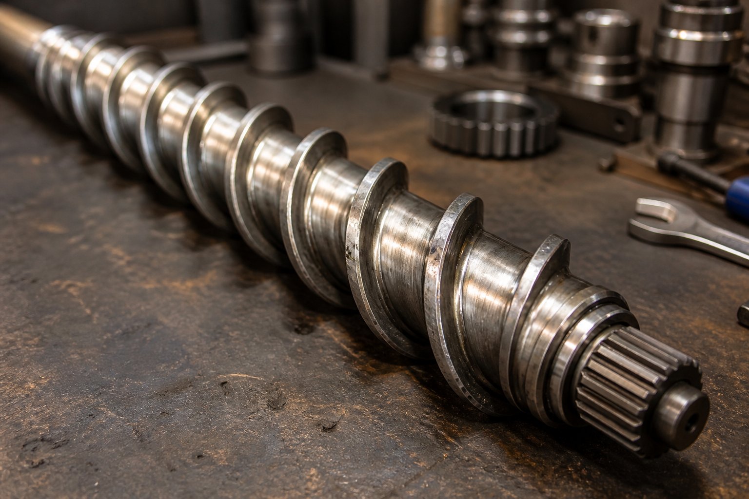
Screw and Barrel Wear Maintenance and Replacement Strategy
That gradual performance drift you notice — a slow decline in throughput, a creeping rise in melt temperature, a subtle loss of dimensional consistency — rarely happens overnight. It builds invisibly, one operating hour at a time, as the precision clearance between your screw flights and barrel bore widens from its original specification. The screw and barrel assembly in any plastic screw extruder operates under punishing conditions: continuous rotational shear forces, barrel temperatures reaching 200 to 300 degrees Celsius, pressures exceeding 1,500 PSI, and direct chemical exposure to aggressive polymers and additives. Under those conditions, wear is not a question of if, but when and how fast.
The critical mistake most plants make is treating wear as a reactive maintenance event — waiting until output drops enough to trigger an emergency shutdown. By that point, you have already absorbed weeks or months of degraded product quality, increased scrap rates, and higher energy consumption that went unnoticed because the decline was incremental. A proactive approach starts with understanding exactly how your extruder screws and barrels wear, what signs to watch for, and when the economics favor replacement over continued operation.
Abrasive, Corrosive, and Adhesive Wear Mechanisms
Not all wear looks the same, and the type of degradation attacking your extruder screw barrel depends heavily on what you are processing. Three primary mechanisms account for roughly 95% of all screw and barrel wear, each driven by different material interactions and each producing distinct damage patterns.
Abrasive wear is the most common culprit, responsible for approximately 50% of all wear cases. It occurs when hard particles in the polymer formulation physically grind against the metal surfaces of the screw flights and barrel bore. Glass-fiber-reinforced resins are the worst offenders — a 30% glass-filled nylon compound acts like liquid sandpaper inside your barrel. Mineral fillers such as calcium carbonate, talc, and silica produce similar abrasive effects, though typically at lower intensity. Recycled plastics introduce another abrasive risk: metallic fragments, sand, and other contaminants from upstream processing can accelerate wear rates dramatically if filtration is inadequate.
The damage pattern from abrasive wear is distinctive. Screw flight tips lose material progressively, reducing the outside diameter of the screw. The barrel bore widens as hard particles score the inner surface. Both changes increase the flight clearance — the gap between screw tip and barrel wall — and that widening gap is where performance loss originates. As the clearance grows, molten polymer leaks backward over the flights instead of being pumped forward, reducing volumetric efficiency and increasing melt temperature because the same material gets sheared repeatedly.
Corrosive wear accounts for roughly 15% of wear cases and targets operations processing halogenated polymers. PVC and PVDF release hydrochloric acid and hydrofluoric acid gases when heated, and these corrosive byproducts attack standard steel surfaces from the inside out. Flame retardant additives containing bromine or chlorine compounds amplify the corrosive environment. Unlike abrasive wear, which physically removes material through grinding, corrosive wear chemically degrades the metal surface, creating pitting, surface roughening, and eventual material loss. The insidious aspect of corrosive wear is that it often acts synergistically with abrasive wear — a chemically weakened surface erodes far faster when abrasive particles are also present.
Adhesive wear occurs at metal-to-metal contact points and is responsible for around 30% of wear cases. When polymer degradation creates sticky residue on screw or barrel surfaces, localized hot spots develop. Thermal cycling causes material bonding between the screw flight tips and barrel wall, and as the screw rotates, welded micro-junctions tear apart, pulling metal from one surface to the other. Poor barrel alignment — especially on long, large-diameter extruders — exacerbates adhesive wear by forcing the screw into sustained contact with one side of the barrel. Barrel alignment should be checked whenever a barrel is removed or changed, if the foundation shifts, or if barrel supports move, because even slight misalignment creates asymmetric contact forces that accelerate wear on one side while leaving the opposite side untouched.
Inspection Intervals and Wear Measurement
Knowing what causes wear is only useful if you can detect and measure it before it degrades your output beyond acceptable limits. Practical wear assessment requires two things: the right measurement tools and a disciplined inspection schedule.
For extruder screws, the key measurement is the outside diameter of the screw flights. A custom OD bar micrometer — modified with a bar that spans across the flights — provides the precision needed, typically within plus or minus 0.01 mm. Before measuring, all solidified polymer residue must be removed from the screw surface using brass tools and copper gauze. Steel wire brushes or aggressive abrasives will damage the surface and give false readings.
For extruder barrels, an inside bore gauge or ultrasonic thickness measurement tool maps the internal diameter at multiple points along the barrel length. Measurements should be taken at the feed, transition, and metering zones because wear rates differ across zones — the transition zone, where solid pellets compress against the barrel wall, typically shows the most aggressive wear pattern.
As a widely referenced guideline, the flight clearance on a new screw is approximately the nominal screw diameter divided by 1,000 per side. For example, a 3.5-inch extruder has a new flight clearance of about 0.004 inches per side. Once that clearance widens — through either screw OD reduction or barrel ID increase — pumping efficiency drops and melt quality suffers.
How often should you pull the screw and measure? That depends on your material. Operations running unfilled polyolefins on standard steel screws might inspect every 4,000 to 5,000 operating hours. Glass-fiber-filled or mineral-filled compounds accelerate the timeline to every 2,000 to 3,000 hours. PVC lines should include quarterly corrosion checks even if abrasive wear is minimal. Between scheduled pulldowns, monitor these in-process warning signs that signal wear is approaching critical levels:
- Reduced throughput at the same screw speed — the most direct indicator that flight clearance has widened and polymer is leaking back over the flights instead of being pumped forward
- Rising melt temperature at constant RPM — leaking polymer recirculates through the clearance gap, absorbing additional shear energy with each pass
- Inconsistent or erratic melt pressure readings — worn clearances reduce the screw's ability to build stable pressure, causing fluctuations that show up as surging at the die
- Higher motor current draw at the same operating conditions — the extruder works harder to maintain output as pumping efficiency drops
- Increased scrap rate or product dimensional drift — subtle quality changes that accumulate gradually and often go unnoticed until they breach tolerance limits
- Visible scoring, gouging, or discoloration on the screw surface during routine visual checks — surface damage that points to active abrasive, adhesive, or corrosive attack
Tracking these indicators on a regular log — ideally tied to production hours rather than calendar dates — creates a wear trend that allows you to predict replacement timing rather than react to failure. For critical-duty processes like medical extrusion, screws may need replacement after the flight clearance reaches just 2x the new clearance, while less demanding applications such as corrugated pipe can tolerate significantly higher wear levels before product quality is affected.
When to Refurbish vs Replace Your Screw and Barrel
Once your measurements confirm that wear has crossed acceptable thresholds, you face a practical decision: refurbish or replace? The answer depends on five factors — extent of damage, economics, metallurgical compatibility, lead time, and long-term production planning.
Refurbishment — typically involving re-welding hard facing material onto worn screw flight tips and honing or relining barrel bores — makes economic sense when wear is moderate and localized. If your barrel shows excessive wear in only one zone while the rest remains within spec, relining that section costs far less than a full barrel replacement. Similarly, a screw with worn flight tips but an intact root diameter can be rebuilt to original specifications. The general rule: if the cost of repair is less than 40% of replacement cost, and the component still meets structural requirements, refurbishment is the financially sound choice.
There are limits, however. A screw should never be refurbished more than three times, because each welding cycle deteriorates the base metal, increasing the risk of delamination between the hard facing and the underlying steel. After three rebuilds, the structural integrity of the screw root and flight transitions becomes unreliable, and catastrophic failure during operation becomes a real — and costly — possibility.
Replacement is the clear choice when wear is severe, widespread, or involves corrosive damage that has compromised the base metal. It is also the better option when you are changing resin types and the existing screw geometry no longer matches your new processing requirements. Why rebuild a screw designed for polyolefins if you are transitioning your line to run engineering plastics that need a completely different compression ratio, L/D, and venting configuration?
The same decision logic applies to injection molding screws and barrels in plasticating units — worn clearances reduce shot-to-shot consistency and increase cycle times. Whether you operate extrusion lines or molding cells, the metallurgy and geometry precision of replacement components directly determine how long your next service interval will last.
This is where sourcing quality matters enormously. A replacement screw machined from the wrong alloy, or a barrel with an imprecise bore, will wear faster than the component it replaced. When evaluating suppliers, prioritize those offering material-specific metallurgical options — nitrided steel for general-purpose applications, bimetallic coatings for glass-filled compounds, and corrosion-resistant alloys for PVC and fluoropolymer processing. Specialist manufacturers like NANHAIYA provide custom replacement screws and barrels engineered to match your exact geometry, metallurgy, and application requirements across pipe, profile, film, sheet, and pelletizing lines. Working with a supplier that understands your specific extrusion process — not just generic dimensions — reduces the risk of mismatched components and ensures faster turnaround when downtime is costing you production hours.
One additional consideration that many maintenance teams overlook: keep a spare screw in storage. When the current screw reaches end of service life, the spare can be installed without shutting down the line for the weeks it takes to manufacture or refurbish the worn component. The worn screw then goes out for rebuild or becomes the reference for ordering a replacement. This rotation strategy — always having a ready spare — transforms screw replacement from an emergency shutdown event into a planned, low-impact maintenance task.
A well-maintained screw and barrel assembly running within specification is the foundation of consistent extrusion performance. But wear is only one category of problem that sends operators chasing defects. Melt quality issues, feed failures, and mechanical anomalies can all mimic the symptoms of worn components — and each requires a different corrective response. Knowing how to differentiate between these root causes is what separates reactive firefighting from systematic troubleshooting.
Troubleshooting Common Plastic Screw Extruder Problems
A worn extruder screw and barrel assembly explains plenty of production headaches — but not all of them. Some of the most frustrating extrusion defects have nothing to do with wear. They trace back to incorrect temperature settings, contaminated feedstock, screw speed mismatches, or feed system failures that look deceptively similar to worn-component symptoms. Jumping to the wrong conclusion costs you time, money, and sometimes a perfectly good screw that gets pulled and measured for no reason.
Systematic troubleshooting means matching symptoms to root causes before reaching for a wrench. The two categories below cover the most common issues operators and maintenance teams face on the production floor, organized so you can diagnose fast and act decisively.
Most extrusion defects trace back to three root causes: worn screw-barrel clearances, incorrect temperature profiles, or contaminated feedstock.
Melt Quality and Output Consistency Problems
Unmelted particles (gels) showing up in your extrudate are a clear sign that the polymer did not receive enough thermal or mechanical energy to fully plasticize. The usual suspects? Screw speed set too high — reducing residence time below what the resin needs — or a compression ratio too low for the material being processed. A worn screw and barrel clearance can also be the culprit, because widened flight gaps allow polymer to bypass the high-shear compression zone entirely. The fix starts with verifying that your screw geometry matches your resin's requirements, then checking barrel zone temperatures in the transition section. If temperatures and geometry are correct, measure your screw flight OD — gels are one of the earliest visible symptoms of excessive wear.
Melt fracture — that rough, shark-skin texture on the extrudate surface — typically signals that the polymer is being forced through the die at a shear rate exceeding its critical threshold. Reducing screw speed, raising die temperature, or switching to a die with a longer land length usually resolves the issue. In some cases, adjusting the extrusion barrel temperature profile to deliver a hotter, lower-viscosity melt to the die is the simplest correction.
Surging output — rhythmic fluctuations in extrudate thickness or weight — is one of the most common and most maddening problems. It can originate from inconsistent solids feeding, temperature oscillations in the barrel zones, or a worn metering section that cannot build stable pressure. Start by checking the feed system for bridging or inconsistent pellet flow. If feeding is stable, review your PID controller tuning on barrel heaters — poorly tuned controllers can create cyclical temperature swings that translate directly into output surging. Worn screw flights in the metering zone are the third possibility, identifiable through melt pressure variation readings at the die.
Poor color dispersion — streaks, swirls, or uneven tint in the extrudate — points to insufficient mixing. On a single-screw machine, this often means the screw lacks an adequate mixing section. On twin-screw systems, worn kneading blocks lose their ability to generate the shear needed for uniform pigment distribution. Increasing back pressure by tightening the screen pack can improve mixing as a short-term fix, but addressing the root cause usually means upgrading the screw configuration with dedicated dispersive mixing elements.
Mechanical and Feed-Related Extrusion Failures
Feed bridging at the hopper throat stops production cold. Material forms a solid arch above the feed opening and refuses to drop into the screw channel. High-moisture pellets, irregular particle shapes, and an overheated feed throat are the primary causes. When the feed throat temperature climbs too high, pellet surfaces soften and stick together, creating a plug. Keeping the feed throat cooling jacket operational and maintaining inlet temperatures between 20 and 40 degrees Celsius prevents most bridging events. For materials prone to clumping — hygroscopic additives, recycled flake with inconsistent geometry — installing a hopper agitator or vibrator breaks the bridge before it fully forms.
Excessive motor load is your extruder telling you something is wrong upstream. Overfeeding, processing a higher-viscosity resin than the machine is configured for, or a blocked screen pack can all spike motor current beyond safe operating limits. Reducing screw speed and feed rate simultaneously brings the load back within range while you identify the root cause. Check for material buildup inside the barrel, verify the resin grade matches your process settings, and inspect the gearbox and bearings for increased friction from inadequate lubrication.
Barrel overheating — where actual barrel temperatures exceed setpoints despite cooling — indicates that shear heating from the screw has overwhelmed the cooling system's capacity. This commonly occurs when screw speed is too high for the resin viscosity, or when the cooling water lines have accumulated mineral scale that restricts flow. Flushing cooling channels and verifying flow rates at each zone is the first corrective step. If overheating persists, reduce RPM or evaluate whether your screw design generates more shear than your resin requires.
Quick-Reference Troubleshooting Table
The table below consolidates the most frequent extrusion problems into a scannable reference format. Bookmark it — you will come back to it.
| Problem | Likely Causes | Recommended Solutions |
|---|---|---|
| Unmelted particles (gels) | Screw speed too high (short residence time); compression ratio too low for resin; worn screw and barrel clearance allowing material bypass | Reduce RPM; verify screw compression ratio matches resin type; measure screw OD and barrel ID for wear; raise transition zone barrel temperatures |
| Melt fracture (shark skin) | Die shear rate exceeds polymer's critical threshold; melt temperature too low at die exit | Reduce screw speed; increase die zone temperature; use a die with longer land length; apply a processing aid if resin-compatible |
| Output surging | Inconsistent solids feeding; barrel temperature oscillations from poor PID tuning; worn metering zone flights | Inspect feed system for bridging; retune PID controllers; measure metering zone screw flights for wear; check back pressure consistency |
| Poor color or additive dispersion | Insufficient mixing capability in screw design; worn kneading blocks (twin-screw); low back pressure | Add or upgrade mixing section on screw; replace worn kneading elements; increase screen pack mesh to raise back pressure |
| Feed bridging | Overheated feed throat; high-moisture or irregularly shaped pellets; hopper design with steep angles | Verify feed throat cooling is active (20-40 degrees C); install hopper agitator or vibrator; pre-dry hygroscopic materials; use anti-bridging hopper geometry |
| Excessive motor load | Overfeeding; resin viscosity higher than configured; blocked screen pack or die; insufficient gearbox lubrication | Reduce feed rate and screw speed simultaneously; verify resin grade; clean screen pack and die passages; inspect gearbox oil level and bearing condition |
| Barrel overheating beyond setpoint | Excessive shear heating from high RPM; scale buildup in cooling water channels; cooling system pump failure | Reduce screw speed; flush and descale cooling lines; verify cooling water flow rates per zone; evaluate if screw design generates excessive shear for the application |
| Screw breakage | Foreign metal contamination in feed; startup with cold, solidified polymer in barrel; extreme torque overload from mismatched process settings | Install magnetic separators upstream of feed throat; always purge and heat barrel to processing temperature before engaging screw rotation; verify startup procedures follow manufacturer guidelines |
Notice a pattern in this table? Nearly every problem has multiple possible causes, and the most effective troubleshooting approach works by elimination — start with the simplest, lowest-cost check (feed system, temperature readings, screen pack condition) before pulling the screw for measurement or replacement. An operator who reflexively blames the extruder screw and barrel for every defect will spend far more on unnecessary component changes than one who systematically rules out process and feedstock issues first.
Diagnosing and fixing problems on your current line is essential — but so is avoiding them on your next equipment purchase. The extruder architecture, screw geometry, and supplier you choose upfront determine how many of these troubleshooting scenarios you will face over the machine's lifetime. Making that selection with a structured, resin-driven decision framework prevents the most expensive problem of all: buying the wrong machine.
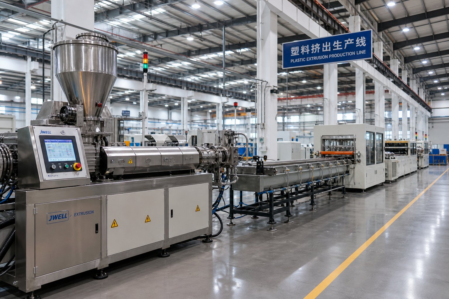
How to Choose the Right Plastic Screw Extruder for Your Needs
Buying the wrong extruder is not a mistake you discover on delivery day. It reveals itself slowly — six months into production when throughput never reaches the quoted spec, when your screw design cannot handle the filler loading your product requires, or when a resin change forces you to retrofit a machine that was never designed for it. Every underperforming line in the troubleshooting table above started with a procurement decision, and the most expensive fix in extrusion is replacing a machine that should never have been purchased in the first place.
The challenge is that extruder selection involves at least five interdependent variables — resin type, product geometry, throughput target, compounding needs, and total budget — and optimizing for one without considering the others leads to a mismatch somewhere in the system. What you need is a structured sequence that narrows options logically, eliminating bad fits early before you ever request a quote.
Step-by-Step Extruder Selection Decision Framework
Walk through these five decision points in order. Each one filters your options and feeds directly into the next. Skipping ahead — say, choosing a machine based on price before defining your resin requirements — is how plants end up with equipment that looks like a bargain on paper and costs a fortune in lost production.
- What resin or resin blend are you processing?
- Identify whether your polymer is semi-crystalline (PE, PP, Nylon), amorphous (ABS, PS, PC), or thermally sensitive (PVC, PLA).
- Determine shear sensitivity — does the resin degrade under aggressive compression, or does it require high shear input to melt through a crystalline phase?
- Check moisture sensitivity — hygroscopic resins like PET and PA need vented screws or two-stage designs with devolatilization capability.
- If processing recycled feedstock, assume variable bulk density, contamination risk, and inconsistent melt flow index. This alone often pushes the decision toward twin-screw platforms.
- What is your end product shape?
- Pipe or tube — requires steady-state pumping with excellent pressure consistency; single-screw or counter-rotating twin-screw depending on resin.
- Profile (window frames, trim, decking) — demands precise die pressure distribution; PVC profiles favor conical or counter-rotating twin-screw machines.
- Film (blown or cast) — melt homogeneity and temperature uniformity are critical; single-screw with barrier design and mixing section, or co-rotating twin-screw for multi-layer co-extrusion.
- Sheet — similar requirements to film but at higher throughput per unit width; L/D ratios of 28:1 to 32:1 are common.
- Pellets (compounding) — mixing intensity is paramount; co-rotating twin-screw with modular elements is the default choice.
- What is your target throughput?
- Throughput determines the extruder diameter. A 60 mm single-screw machine operates in a fundamentally different output class than a 120 mm machine — you cannot simply run the smaller one faster to compensate.
- L/D ratio interacts with diameter to set the available screw real estate. As the L/D ratio guide from BLOOM Engineering explains, longer L/D provides stable output at higher screw speeds rather than raw throughput gains. For most commodity polymers, specific output plateaus past about 30:1, meaning extra length buys stability rather than volume.
- Always spec the extruder to run at 60 to 75% of its maximum rated screw speed for your target output. Running continuously at maximum RPM accelerates wear and degrades melt quality.
- Do you need compounding or just forming?
- If your incoming material is pre-compounded pellets that simply need melting and shaping, a single screw extruder is almost always the most cost-effective and reliable choice. Single screw extrusion handles forming applications — pipe, film, sheet, profiles — with lower capital cost, simpler operation, and easier maintenance.
- If you are blending polymers, incorporating high filler loads, dispersing pigments, performing reactive extrusion, or processing inconsistent recycled streams, a co-rotating twin-screw extruder delivers the mixing intensity and modular flexibility these tasks demand.
- Some operations straddle both worlds — compounding upstream on a twin-screw line and forming downstream on a single-screw machine. This two-stage approach lets each platform do what it does best.
- What is your total budget, including downstream equipment?
- The extruder itself is typically 30 to 50% of total line cost. Dies, calibration tanks, cooling baths, haul-offs, cutters, and controls make up the rest. Budgeting only for the extruder and scrambling for downstream equipment later leads to mismatched line capabilities.
- Factor in ongoing costs: energy consumption scales with screw diameter and L/D. A 36:1 machine can cost 30 to 50% more than an equivalent 24:1 line for the additional barrel length, heating zones, and drive motor capacity alone.
- Consider spare parts economics. Twin screw barrel segments, modular screw elements, and gearbox components carry higher replacement costs than single-screw equivalents. Build these recurring expenses into your total cost of ownership calculation before signing a purchase order.
Following this sequence does not guarantee a perfect outcome, but it eliminates the most common procurement errors: buying a co-rotating twin-screw when a single-screw would have handled the job at half the cost, under-sizing the diameter and then running the screw at maximum RPM to compensate, or specifying a short L/D barrel for a resin that needs venting and extended mixing. Each of these mistakes traces back to skipping one of the five steps above.
For operations evaluating the secondary market, this same framework applies when assessing a used twin screw extruder for sale. A used machine at an attractive price is only a bargain if its architecture, diameter, and L/D match the resin and product you actually plan to run. A used twin screw extruder for sale at 40% of new cost becomes a liability if its barrel bore is worn beyond spec, its L/D is wrong for your polymer, or its modular elements have been configured for a completely different formulation. Always measure the barrel ID and screw flight OD before purchasing secondhand equipment, and validate the screw element configuration against your process requirements.
Where to Source Extruder Machines and Screw Barrel Support
Selecting the right extruder architecture and size is only half the procurement challenge. The supplier you choose determines whether that machine performs to spec on day one and maintains that performance over years of production. Whether you are sourcing a complete new extrusion line, replacing worn screws and barrels on an existing machine, or evaluating a used Davis Standard extruder or comparable US extruders for refurbishment, the supplier evaluation criteria remain the same.
Here is what separates a reliable equipment partner from one that ships a box and disappears:
- Metallurgical options for screws and barrels — The supplier should offer application-matched materials: nitrided steel (38CrMoAlA) for general-purpose processing, bimetallic barrel linings for glass-fiber-filled and mineral-filled compounds, and corrosion-resistant alloys for PVC and fluoropolymer lines. A supplier offering only one metallurgy for all applications is not equipped to serve diverse production environments.
- Geometry customization capability — Your replacement screw must match the exact compression ratio, flight depth progression, L/D, and mixing section configuration your process requires. Generic, catalog-only suppliers rarely deliver the precision fit that maintains output quality. Look for manufacturers who reverse-engineer from your existing components or work from your process specifications to deliver screws and barrels optimized for your specific resin and product.
- Support across multiple line types — A plant running both pipe extrusion and blown film benefits from a supplier that understands the distinct screw design requirements for each line. Suppliers like NANHAIYA serve pipe, profile, film, sheet, and pelletizing lines with custom screw barrel assemblies, which simplifies vendor management and ensures cross-line consistency in component quality.
- Lead time and spare parts availability — When a worn screw shuts down your line, the supplier's turnaround time directly translates to lost production revenue. Ask about standard lead times for custom orders, whether emergency expedited manufacturing is available, and whether the supplier stocks common configurations for immediate shipment.
- After-sale technical support — The best suppliers help you diagnose wear patterns, recommend geometry modifications when you change resins, and provide measurement data that supports your preventive maintenance program. This ongoing relationship is worth more than a one-time price advantage.
The market for extruder equipment ranges from major OEMs like a Davis-Standard extruder line — well-known among US extruders for robust drive and barrel engineering — to specialized component manufacturers focused exclusively on screws and barrels. For complete new lines, OEM packages from established brands offer integrated drive, barrel, and controls engineering with factory support. For replacement components, spare parts, and custom screw designs, specialist manufacturers often deliver faster turnaround, more flexible metallurgical options, and competitive pricing compared to going back to the original equipment maker.
Regardless of which supplier path you choose, one principle holds: the screw and barrel are consumable components that will require replacement multiple times over the life of your extruder. The supplier relationship you establish for those components is not a one-time transaction — it is a long-term partnership that directly affects your line's uptime, product quality, and maintenance costs for years to come. Invest the same rigor in evaluating that partnership as you do in selecting the extruder itself, and the machine you buy will deliver the performance it was designed for.
Plastic Screw Extruder FAQs
1. What are the three functional zones of a plastic screw extruder?
A plastic screw extruder operates through three sequential zones. The feed zone uses a deep, constant-depth screw channel to intake solid pellets and convey them forward using barrel-wall friction. The transition (compression) zone features a progressively shallower channel that compacts and shears the material, generating frictional heat that works alongside barrel heaters to melt the polymer. The metering zone has the shallowest, constant-depth channel, which homogenizes the molten plastic and builds stable pressure to push it through the die. Each zone depends on the one before it — inconsistent solids feeding disrupts compression, and improper compression delivers a poorly conditioned melt that no metering zone can fix.
2. How do I choose between a single screw extruder and a twin screw extruder?
The choice depends primarily on your process requirements. A single screw extruder excels at steady-state forming of pre-compounded resins into pipes, profiles, films, and sheets, offering lower cost and simpler maintenance. A co-rotating twin screw extruder is the better choice when your process demands intensive mixing, such as compounding filled materials, blending multiple polymers, reactive extrusion, or processing inconsistent recycled feedstock. Counter-rotating twin screw systems specialize in heat-sensitive materials like PVC. If you only need to melt and shape a single, well-characterized resin, the single screw platform typically delivers the best cost-to-performance ratio.
3. What compression ratio should I use for my plastic resin?
Compression ratio — the feed zone channel depth divided by the metering zone channel depth — must match your resin's thermal behavior. Semi-crystalline polyolefins like PE and PP need higher compression ratios (3:1 to 4:1) to generate sufficient shear energy for melting through their crystalline phase. Heat-sensitive PVC requires low compression (2:1 to 2.5:1) to avoid thermal degradation. Amorphous styrenics such as ABS and PS perform well with moderate ratios (2.5:1 to 3:1). Always validate these general guidelines against your resin supplier's processing datasheet and your own production trials, as specific grades within each polymer family can vary.
4. How do I know when my extruder screw and barrel need replacement?
Monitor for these key warning signs: reduced throughput at the same screw speed, rising melt temperature without process changes, erratic melt pressure readings, higher motor current draw, and increasing scrap rates. These symptoms indicate that the clearance between screw flights and barrel bore has widened beyond acceptable limits due to abrasive, corrosive, or adhesive wear. Measure screw flight outside diameter and barrel bore diameter at regular intervals — every 2,000 to 3,000 hours for glass-filled compounds, or 4,000 to 5,000 hours for unfilled polyolefins. Specialist manufacturers like NANHAIYA offer custom replacement screws and barrels matched to your exact geometry and metallurgy at nhyscrews.com.
5. Why does my extruder produce unmelted particles or gels in the output?
Unmelted particles typically indicate insufficient thermal or mechanical energy input. The most common causes are screw speed set too high (which reduces residence time below what the resin needs to fully melt), a screw compression ratio that is too low for the polymer being processed, or worn screw-barrel clearances that allow material to bypass the high-shear compression zone. To diagnose, first verify that your screw geometry matches your resin requirements, then check transition zone barrel temperatures. If both are correct, measure your screw flight OD and barrel bore — gels are often the earliest visible symptom of excessive wear requiring component replacement.
Written by
Nanhaiya Technical Team
Zhoushan Nanhaiya Plastic Machinery Co., Ltd.
The Nanhaiya technical team supports screw and barrel manufacturing projects through application review, technical communication, custom manufacturing coordination, and production and quality control.
Discuss Your Application
Related Articles
More insights on screw barrel technology and plastics processing.

What Nobody Tells You About Screw Barrel For Plastic Machine Design
Oct 10, 2026
Learn how screw barrel for plastic machine design affects melt quality, throughput, and wear life. Covers geometry, resin matching, troubleshooting, and sourcing.
Read Article
Single Screw Extruder for Sheet: Stop Guessing, Start Specifying
Oct 9, 2026
Learn how to specify a single screw extruder for sheet production. Covers screw geometry, resin-specific processing, troubleshooting, and maintenance best practices.
Read Article
PE Pipe Extruder Machine: What Datasheets Won't Tell You
Oct 9, 2026
Learn how a PE pipe extruder machine works, key specs explained, material grade selection, maintenance tips, and buyer guidance beyond the datasheet.
Read ArticleLooking for something else?
Search by material, symptom or product and jump straight to the relevant page.
These are navigation suggestions based on keyword matching — not a quotation, not a delivery commitment, and not a substitute for engineering review. Final specification is confirmed by our engineers against your drawings and processed material.
Need help with screw barrel selection?
Share your machine model, processed material and application. Our team can help with pricing and technical support.