

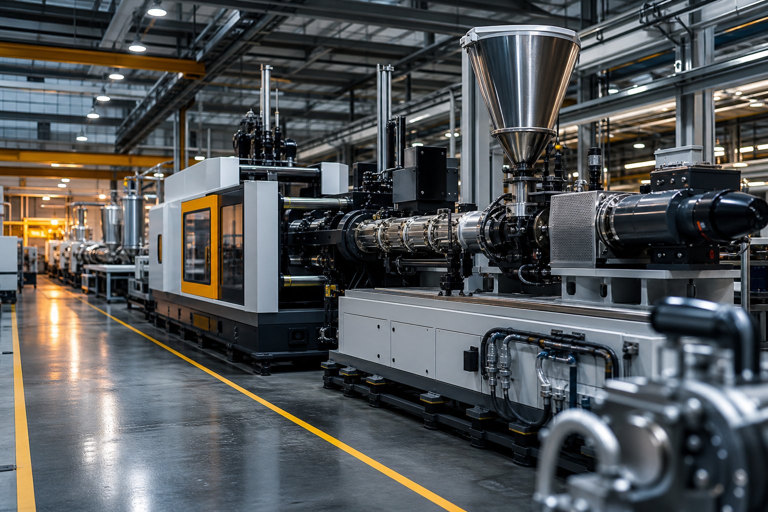
What Is Plastic Processing and Why It Matters
Plastic processing is the broad category of industrial operations that convert raw polymer resins into finished or semi-finished products through the controlled application of heat, pressure, and mechanical shaping. Whether you are producing a syringe barrel, an automotive dashboard, or a hundred thousand bottle caps per day, every plastic part you encounter began as a raw resin that was transformed through one of these operations.
The scope is enormous. Injection molding, extrusion, blow molding, thermoforming, rotational molding, compression molding, and casting are just the most common entries on a list that runs into dozens of distinct techniques. Each one serves different part geometries, production volumes, and material requirements - and each touches virtually every manufacturing sector, from medical devices and consumer electronics to construction, packaging, and aerospace.
Defining Plastic Processing in Modern Industry
Think of polymer processing as the point where materials science meets manufacturing engineering. It demands simultaneous knowledge of how polymers behave under heat and stress, how tooling must be designed to shape molten or softened resin, and how thermal management governs everything from cycle time to final part quality. A processing engineer is not just running a machine - they are managing a complex interaction between material chemistry, mechanical forces, and energy transfer.
This interdisciplinary nature is exactly what makes plastics processing both powerful and challenging. Advances in plastic technology continue to expand what is possible: thinner walls, tighter tolerances, faster cycles, and more sustainable material choices. Yet the fundamentals remain the same. You are taking a polymer, bringing it to a workable state, shaping it inside or against a tool, and then stabilizing that shape through cooling or curing.
Why Understanding Processing Methods Matters
Here is the part that catches most teams off guard: the method you select does not just shape the part - it shapes the entire project economics.
The processing method you choose determines up to 70% of your final part cost - yet most engineers inherit a default process rather than evaluating alternatives.
Selecting the wrong process wastes material, inflates tooling investment, and delays time-to-market. Imagine specifying injection molding for a large hollow tank that rotational molding could produce at a fraction of the tooling cost. Or defaulting to machining prototypes from solid stock when thermoforming could deliver functional test parts faster and cheaper. These are real decisions with real budget consequences, and they happen more often than most procurement professionals realize.
This article offers a neutral, comprehensive walkthrough of every major method - from raw material origins and resin selection through part design, process parameter optimization, and post-processing. Unlike resources that champion a single technique or skip cost and sustainability discussions entirely, you will find a balanced evaluation designed to help you match your specific production challenge to the right technology. The goal is straightforward: give you the knowledge to make informed, confident processing decisions rather than defaulting to "the way it has always been done."
That decision-making process starts well before any machine is switched on. It begins with understanding where plastic resins come from and how their chemistry dictates which processes are even on the table.
How Plastic Is Made From Raw Materials to Resin
Every polymer resin arriving at your processing facility has already completed a remarkable chemical journey. Understanding how plastic is made - from raw feedstock to pelletized compound - gives engineers and procurement professionals a shared language with their resin suppliers and a clearer picture of why certain materials behave the way they do under heat and pressure.
From Crude Oil to Polymer Resin
So how do you make plastic from something as complex as crude oil? The journey starts with extraction and refining. Crude oil is heated in a furnace and fed into a fractional distillation column, where it separates into lighter and heavier fractions based on boiling point. One of those fractions - naphtha, a mixture of C5 to C10 hydrocarbons - is the primary feedstock for most commodity plastics.
Naphtha and other light fractions then undergo cracking, a high-temperature process that breaks long hydrocarbon chains into smaller, reactive molecules called monomers. Steam cracking uses intense heat and pressure without a catalyst, while catalytic cracking achieves similar results at lower temperatures by introducing a catalyst. The resulting monomers - ethylene, propylene, butylene, and styrene among them - are the building blocks of polymer manufacturing.
These monomers are then linked together through polymerization, and two main mechanisms dominate. In addition polymerization, a catalyst triggers monomers to bond end-to-end in a growing chain, one unit at a time. Polyethylene, polypropylene, and polystyrene are all produced this way. In condensation polymerization, two different monomers react and release a small byproduct - typically water - as they bond. Nylon and polyester are classic condensation polymers. How can we make plastic from renewable sources? Bio-based alternatives follow a parallel path, deriving monomers from carbohydrates, vegetable oils, or bacterial fermentation rather than petroleum, though the polymerization chemistry remains fundamentally similar.
Compounding and Preparing Plastic for Manufacturing
Raw polymer resin alone rarely meets the demands of a finished product. This is where compounding of plastics enters the picture. Compounding is the process of melt-blending base resin with carefully selected additives - stabilizers to resist UV or thermal degradation, colorants for aesthetics, mineral fillers for stiffness, glass fibers for strength, and flame retardants for safety compliance. The blended material is typically processed through a twin-screw extruder, then cooled and cut into uniform pellets ready for downstream forming operations.
Why does this matter for processing? Because every compounding decision cascades directly into your machine settings. A heavily filled compound behaves differently under shear than a neat resin. A flame-retardant formulation may narrow the safe temperature window. Choosing or changing additives is never just a material decision - it is a processing decision too.
This is also the right moment to draw a fundamental line that constrains every process choice you will make: the distinction between thermoplastics and thermosets.
| Property | Thermoplastic | Thermoset |
|---|---|---|
| Re-meltability | Can be reheated, melted, and reshaped multiple times with minimal property loss | Permanently cross-linked during curing; cannot be re-melted once set |
| Typical Processing Methods | Injection molding, extrusion, blow molding, thermoforming | Compression molding, reaction injection molding (RIM), resin transfer molding (RTM) |
| Recyclability | Mechanically recyclable; pellets can be reprocessed | Difficult to recycle due to irreversible cross-links |
| Heat Resistance | Softens or deforms at elevated temperatures | Retains structural integrity under high heat |
| Common Examples | PE, PP, PS, PVC, PC, ABS, Nylon | Epoxy, phenolic, polyurethane, silicone, melamine |
As TWI notes, thermoplastics soften when heated and can be recycled, while thermosets form permanent chemical cross-links during curing that prevent re-melting. This single characteristic - reversibility versus permanence - determines which family of processes is even viable for a given application.
Understanding Polymer Grades and Melt Behavior
Even within the same polymer type, not all grades perform alike. Imagine two polypropylene resins sitting side by side on a supplier's data sheet. One has a high melt flow index (MFI), meaning it flows easily under heat and pressure - ideal for thin-walled injection-molded parts. The other has a low MFI, offering greater melt strength that suits extrusion or blow molding applications where the material must hold its shape before cooling.
Thermal stability is equally critical. It defines how long a resin can remain at processing temperature before it begins to degrade, discolor, or lose mechanical properties. Resins with narrow thermal stability windows - PVC is a well-known example - demand precise barrel temperature control and shorter residence times to avoid degradation.
Together, melt flow index and thermal stability act as the two gatekeepers of process compatibility. They tell you not just how a polymer is manufactured, but how it will behave inside your specific machine, and they set the stage for the detailed material-to-process mapping framework explored later in this article.
With resin in pellet form and its thermal personality understood, the next question becomes practical: which shaping method turns those pellets into the exact geometry your application demands?
Primary Plastic Molding Methods Compared
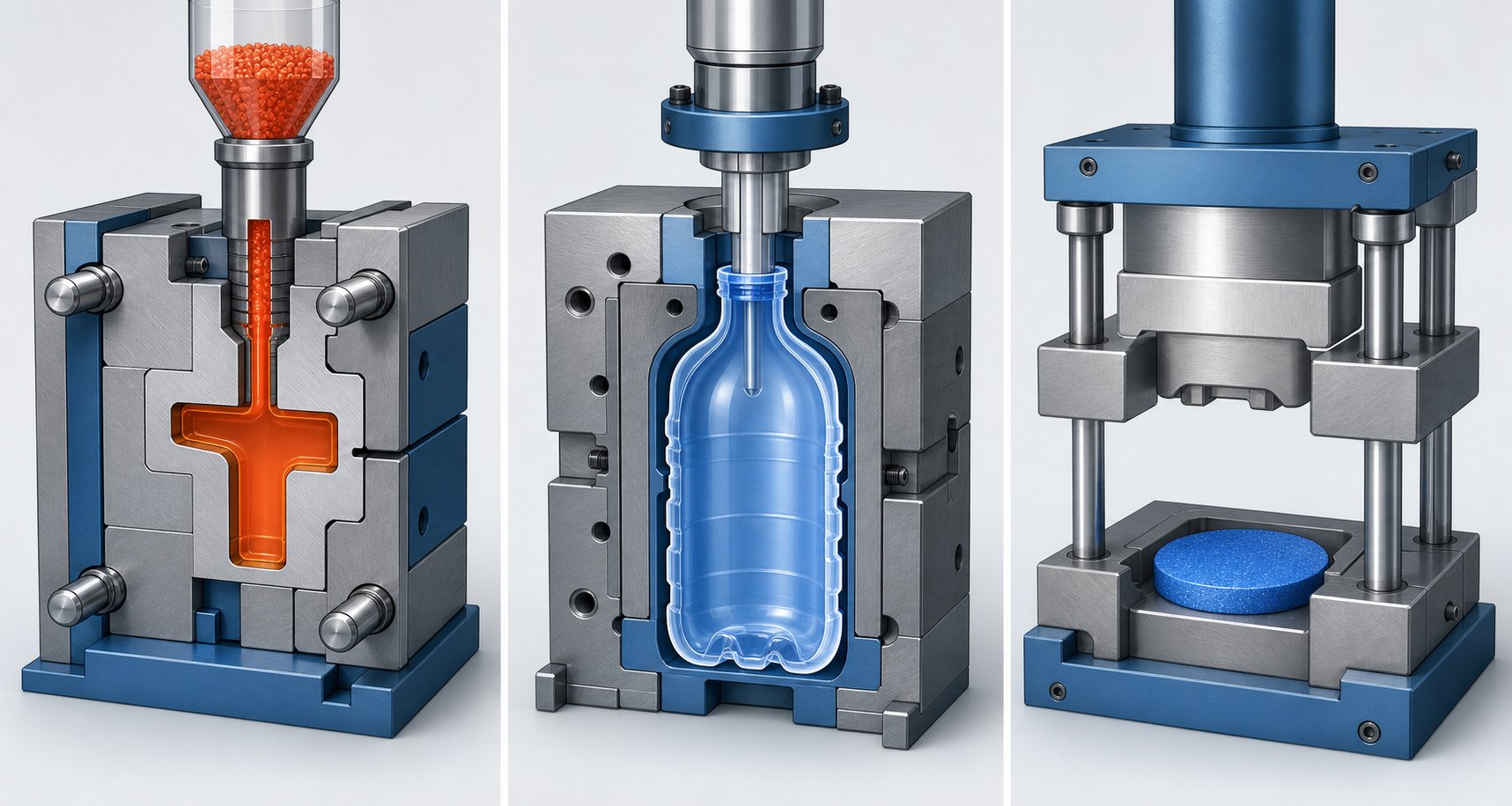
Turning pelletized resin into a finished part means choosing among a surprisingly long list of shaping techniques. Yet three methods dominate global output by volume: injection molding, blow molding, and compression molding. Each excels in a different corner of the design space, and understanding how they differ is the fastest way to avoid costly mismatches between your part requirements and your production line. What follows is a balanced look at each plastic molding process - its mechanics, strengths, and trade-offs - so you can evaluate alternatives rather than default to the familiar.
Injection Molding for Complex High-Volume Parts
The plastic injection molding process follows four tightly choreographed phases. First, a clamping unit locks two mold halves together under significant force. Molten thermoplastic is then injected into the closed cavity at high pressure, filling every detail of the tool geometry. The part cools and solidifies inside the mold, and finally the machine ejects the finished piece - often in a cycle time as short as 10 seconds.
The advantages are hard to ignore. You get tight tolerances, complex geometries with features like snap-fits and living hinges, and exceptional repeatability across runs that can exceed 100,000 parts. Material waste stays low because runners and sprues are often regrindable, and post-processing is minimal thanks to high-quality surface finishes straight from the mold.
The trade-offs? Tooling is the big one. Steel molds for high-volume production represent a significant capital investment and can take up to 12 weeks to fabricate. Design changes after mold fabrication are expensive and limited - you can remove steel to add plastic to a part, but not the other way around. For smaller runs, aluminum tooling can soften the cost impact, but injection molding generally rewards volume. Below roughly 10,000 units, the per-part economics shift rapidly.
Blow Molding for Hollow Plastic Products
When the part you need is hollow - a bottle, a tank, an automotive duct - the plastic blow moulding process is purpose-built for the job. The core idea is straightforward: heat plastic into a soft, workable form, enclose it in a mold, and inflate it with compressed air until it conforms to the cavity walls.
Three main variants serve different applications. Extrusion blow molding (EBM) extrudes a hollow tube of molten plastic called a parison, clamps a mold around it, and blows it into shape. It handles large parts, complex shapes with handles, and works well with HDPE and PP. Injection blow molding (IBM) first injection-molds a preform around a core rod, then transfers it to a blow mold for inflation. This approach delivers very consistent dimensions and suits small to medium containers like pharmaceutical and cosmetic bottles. Stretch blow molding (SBM) adds a mechanical stretching step that orients the polymer chains, producing PET bottles with excellent clarity, strength, and reduced material weight - the reason it dominates beverage packaging worldwide.
Blow molding shines where hollow geometry is the requirement, but it is not designed for solid, detail-rich parts. Wall thickness control varies by variant, and material choices are narrower than injection molding, particularly for SBM, which is primarily limited to PET and a few specialty resins.
Compression and Transfer Molding for Thermosets
Recall that thermosets undergo irreversible cross-linking during curing. This chemical permanence makes them impossible to inject in the same way thermoplastics flow, so they require a different approach. Compression molding - the oldest plastic forming technique - places a pre-measured charge of material directly into a heated open mold cavity. The mold closes, applying heat and pressure simultaneously to force the material into shape while it cures. Tooling costs stay relatively low, and material waste is minimal because the charge is precisely measured.
Transfer molding bridges the gap between compression and injection methods. Material is placed into a separate heated chamber (the transfer pot) and then forced through runners and sprues into the mold cavity. This extra step delivers better flow control around delicate inserts - metal pins, electrical components - and accommodates more complex geometries than compression molding alone.
Both methods serve thermoset plastics, rubber, and high-strength composites that injection molding cannot process. You will find them behind automotive panels, electrical housings, and heavy-duty industrial components where heat resistance and structural rigidity outweigh cycle-time considerations.
Types of Plastic Molding at a Glance
Choosing among these types of plastic molding comes down to matching your part's geometry, volume, and material requirements to the method that delivers the lowest total cost without sacrificing quality. The table below lays the comparison side by side.
| Criterion | Injection Molding | Blow Molding | Compression / Transfer Molding |
|---|---|---|---|
| Typical Part Geometry | Solid, complex 3D shapes with fine detail, thin walls, integrated features (threads, snap-fits, hinges) | Hollow forms - bottles, containers, tanks, ducts | Large flat or moderately complex shapes; parts with metal inserts (transfer) |
| Volume Suitability | Medium to very high (10,000 to millions of units) | Medium to very high, depending on variant | Low to medium |
| Tooling Cost Range | High (steel molds); medium with aluminum tooling | Medium | Low to medium |
| Cycle Time | Fast (seconds to under two minutes) | Moderate; SBM lines can be very fast for PET bottles | Slower due to curing time |
| Material Compatibility | Wide range of thermoplastics; some thermosets via specialized equipment | Thermoplastics (HDPE, PP, PET primary); limited thermoset use | Thermosets, rubber, reinforced composites |
| Key Limitations | High upfront tooling cost; long mold lead times; design changes are costly post-fabrication | Limited to hollow parts; wall thickness uniformity varies by variant; narrower material selection | Longer cycle times; less suited for high-detail or very thin-walled parts; higher scrap in transfer molding runners |
No single method wins across every column - and that is exactly the point. The best plastic processing decisions come from weighing all six criteria against your specific part requirements rather than defaulting to the most familiar option.
These three molding methods dominate when the end product is a discrete, shaped part. But a huge share of the polymer world relies on continuous forming instead - processes like extrusion and thermoforming that produce everything from pipe and film to packaging trays and structural profiles. The mechanics, economics, and equipment considerations look quite different.
Extrusion, Thermoforming, and Continuous Forming Technologies
Molding methods produce discrete parts one cycle at a time. Extrusion flips that logic entirely - it produces continuous lengths of material, making it the backbone of pipe, profile, film, sheet, WPC decking, and granulation operations worldwide. If your product has a consistent cross-section or starts as a flat sheet, continuous plastic shaping is likely where your production challenge lands.
Plastic Extrusion and Its Wide Range of Applications
Imagine feeding plastic pellets into a hopper and watching a finished profile emerge continuously at the other end. That is extrusion in essence, though the engineering behind it is anything but simple. Inside the barrel, a rotating screw conveys, compresses, and melts the resin through friction and external heaters. The homogeneous melt is then forced through a shaped die - round for pipe, flat for sheet, annular for blown film - and solidified by downstream cooling systems before being cut or wound to length.
What separates a good extrusion line from a struggling one often comes down to the screw and barrel. Screw geometry - specifically the L/D ratio, compression ratio, and flight depth - directly governs melt quality, throughput, and energy efficiency. A screw designed for polyethylene film will not perform well extruding rigid PVC profiles because the melting behavior, shear sensitivity, and pressure requirements differ fundamentally.
Barrel condition matters just as much. As Plastics Technology details, when the radial clearance between screw flights and the barrel wall increases through wear, leakage flow rises, output drops, and melt temperature climbs - forcing higher RPM and energy consumption to maintain rate. Worn or mismatched screw barrels rank among the most common - and most correctable - causes of extrusion defects like melt fracture, gels, and dimensional inconsistency. Twin-screw extruders, meanwhile, offer superior mixing and material dispersion for compounding, masterbatch production, and filled or heat-sensitive materials. Effective process controls for plastics extrusion start with the screw barrel interface, making component maintenance and selection a high-impact lever for any operation. For teams sourcing replacement screw barrels or custom extrusion components for pipe, profile, film, sheet, WPC, and granulation lines, NANHAIYA's plastic extruder machine and screw barrel support page offers practical, component-level guidance tailored to specific extrusion applications.
Thermoforming and Rotational Molding as Complementary Processes
Not every part suits a continuous profile or a high-volume mold. Thermoforming and rotational molding fill the gaps that extrusion and injection molding leave open, expanding the range of thermoplastic processes available to manufacturers.
Thermoforming heats a flat thermoplastic sheet until pliable, then shapes it against a mold using vacuum, pressure, or mechanical force. It excels where moderate volumes and lower tooling budgets intersect.
- Low tooling investment: Aluminum molds typically cost $5,000 to $50,000 - a fraction of injection molding tooling.
- Fast cycles: Production times range from 15 to 60 seconds per part, depending on complexity.
- Best-fit applications: Food packaging trays, blister packs, automotive interior panels, and medical sterile trays.
- Trade-offs: Lower dimensional precision than injection molding, and sheet waste can run 15% to 40% of the original material.
Rotational molding takes a completely different approach to forming plastics. Powdered resin is loaded into a heated mold that rotates slowly on two axes, coating the interior walls evenly as the polymer melts. The result is a seamless, hollow part with uniform wall thickness.
- Large hollow parts in one piece: Tanks, playground equipment, kayaks, and industrial containers that would be impractical to injection mold.
- Low tooling costs: Aluminum molds keep entry costs accessible, even for custom designs.
- Durability: Parts are stress-free and impact-resistant, well-suited for outdoor and industrial environments.
- Trade-offs: Cycle times run from minutes to hours, limiting high-volume viability, and tolerances are the loosest of any major plastic process technology.
Matching Forming Technology to Production Goals
When should you choose extrusion-based processes over molding-based ones? The answer hinges on geometry and continuity. If your product has a constant cross-section - pipe, tubing, window profiles, decking boards, film rolls - extrusion is almost certainly the most efficient path. If you need a discrete three-dimensional part with complex features, molding methods take over.
Thermoforming occupies a useful middle ground: it starts with extruded sheet and converts it into shaped parts at tooling costs far below injection molding, making it ideal for packaging runs under 50,000 units or for large panels where mold size would make injection tooling prohibitive. Rotational molding stands alone for large, hollow, one-piece products where seamless construction and impact resistance outweigh cycle-time concerns.
The real insight? These methods are not rivals - they are teammates. Many products combine extrusion (to produce the sheet or profile) with a secondary forming step (thermoforming to shape it). Recognizing which combination fits your volume, geometry, and budget is the difference between an efficient line and an expensive compromise.
Selecting the right forming technology, however, is only half the equation. The polymer you feed into that process constrains everything from machine settings to achievable part performance - a relationship that demands its own systematic framework.
Material Selection Framework for Polymer Processing
You can own the most advanced extrusion line or injection molding cell on the market, but feed it the wrong polymer and the results will disappoint every time. Material selection is not a procurement checkbox - it is the single decision that narrows which plastic manufacturing processes are viable, what machine parameters you will need, and how the finished part ultimately performs. Yet most guides treat materials and processes as separate topics. Here, we connect them directly.
Commodity vs. Engineering vs. High-Performance Polymers
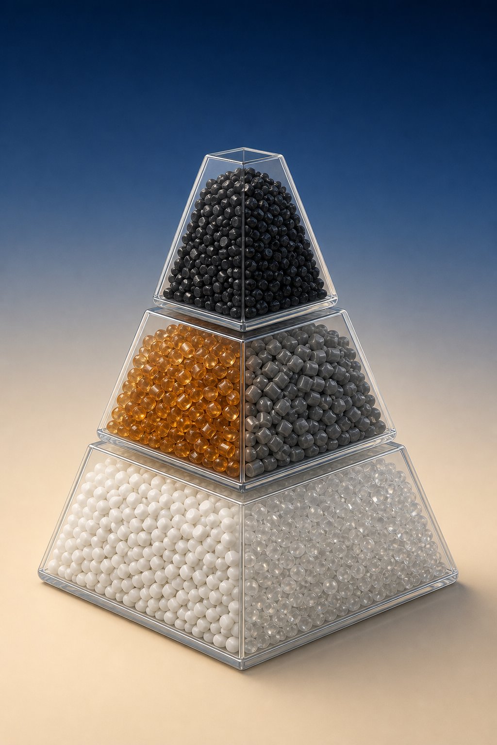
Imagine a pyramid. At the broad base sit commodity polymers - polypropylene (PP), polyethylene (PE), polystyrene (PS), and polyvinyl chloride (PVC). These resins are produced in enormous volumes, priced affordably, and processed on standard equipment across injection molding, extrusion, blow molding, and thermoforming lines. They cover the bulk of packaging, consumer goods, piping, and construction applications.
Move up to the middle tier and you reach engineering polymers - ABS, polycarbonate (PC), polyamide (PA/Nylon), and polyoxymethylene (POM). These materials offer higher mechanical strength, better heat resistance, and tighter dimensional stability than commodity grades. They demand more precise temperature control, often require pre-drying to remove moisture, and generally run on equipment rated for higher pressures and temperatures.
At the narrow peak sit high-performance polymers: PEEK, PEI (Ultem), and PPS. As the Polymer Pyramid framework illustrates, these materials deliver exceptional thermal, chemical, and mechanical performance - but at significantly higher cost and with processing temperatures that can exceed 350 degrees Celsius. Equipment requirements escalate accordingly: hardened screws and barrels, high-temperature heater bands, and precise residence-time control become non-negotiable.
The practical takeaway? Each tier progressively narrows your process and equipment options. A standard general-purpose injection molding machine handles PP effortlessly, but processing PEEK on the same platform without upgrades risks degradation, poor fill, or outright equipment damage. Tier selection is your first filter in the polymer process decision tree.
How Polymer Properties Constrain Process Selection
Within each tier, individual resin properties further dictate which forming method fits best. Four characteristics matter most:
- Melt Flow Index (MFI): A quick measure of how easily a polymer flows under heat and pressure. Research shows that even within a single polymer family like polypropylene, MFI values ranging from 3.6 to 18 g/10 min direct the resin toward entirely different processes - fiber spinning at the low end, spun-bonded nonwovens at the high end, with injection molding occupying the middle ground. Higher MFI grades fill thin-walled molds more easily; lower MFI grades provide the melt strength needed for extrusion and blow molding.
- Thermal degradation window: The gap between a resin's ideal processing temperature and the point where it begins to break down. PVC, for example, has an infamously narrow window that demands precise barrel temperature control and short residence times.
- Viscosity under shear: How the melt responds to the shear rates imposed by screws, runners, and dies. Two polymers with identical MFI values can behave very differently under real processing conditions because MFI is measured at a single shear rate and does not capture the effects of long-chain branching or pressure gradients.
- Crystallinity: Semi-crystalline polymers (PE, PP, Nylon) shrink more and require controlled cooling to manage dimensional accuracy, while amorphous polymers (ABS, PC, PS) offer better optical clarity and more predictable shrinkage but lower chemical resistance.
The manufacturing process of thermoplastics must account for all four properties simultaneously. The table below maps six widely used polymers against their compatible processes and the processing considerations that matter most.
| Polymer | Tier | Compatible Processes | Key Processing Considerations |
|---|---|---|---|
| PP (Polypropylene) | Commodity | Injection molding, extrusion, blow molding, thermoforming | Wide processing window; semi-crystalline with higher shrinkage; MFI grade selection critical for matching process type |
| PE (Polyethylene) | Commodity | Extrusion (film, pipe, sheet), blow molding, injection molding, rotational molding | Multiple density grades (LDPE, HDPE, LLDPE) with very different melt behaviors; excellent chemical resistance |
| ABS | Engineering | Injection molding, extrusion, thermoforming | Amorphous; good flow and surface finish; requires drying before processing to prevent splay marks |
| PC (Polycarbonate) | Engineering | Injection molding, extrusion, blow molding (specialty) | High melt temperature; moisture-sensitive - must be thoroughly dried; susceptible to stress cracking from certain solvents |
| Nylon (PA6, PA66) | Engineering | Injection molding, extrusion, blow molding | Highly hygroscopic - moisture causes hydrolysis and bubbling during processing; semi-crystalline with significant shrinkage; glass-filled grades require hardened tooling |
| PVC | Commodity | Extrusion (pipe, profile, sheet), injection molding, calendering | Narrow thermal window; degrades to release HCl if overheated; requires stabilizers; corrosion-resistant barrel and screw metallurgy recommended |
You will notice a pattern: no polymer is universally compatible with every process. Each resin's thermal personality, flow behavior, and sensitivity to moisture or degradation create a unique fingerprint that must be matched to equipment capabilities. This is why the manufacturing process of thermoplastics is never a one-size-fits-all decision - it is a material-driven equation.
Additives, Fillers, and Their Impact on Processing
Rarely does a raw, unfilled resin go straight from pellet to finished part without some form of plastic formulation adjustment. Glass fibers, mineral fillers, and flame retardants are routinely compounded into thermoplastics to improve strength, stiffness, heat resistance, or regulatory compliance. These additions unlock impressive performance gains - but they also change the rules inside your processing equipment.
Consider glass fiber reinforcement. Adding short glass fibers to nylon can more than double its tensile strength, making it viable for structural brackets and automotive components. However, those same fibers increase melt viscosity, demand higher injection pressures, and create anisotropic properties that depend on fiber orientation during flow. Gate placement and mold design become more critical, not less.
Mineral fillers like talc and calcium carbonate improve dimensional stability and reduce shrinkage in polypropylene, making them popular in automotive interiors and appliance housings. They are generally less abrasive than glass, but at high loading levels they still stiffen the melt and can degrade surface finish quality.
The equipment impact is equally important. Abrasive fillers - glass fibers, carbon fibers, mineral powders - accelerate wear on screws, barrels, and mold surfaces. Hardened tool steels become necessary rather than optional, and screw barrel replacement intervals shorten significantly when running high-filler-content compounds. Flame retardants can introduce additional challenges: some formulations are corrosive to standard barrel metallurgy, while others narrow the already tight thermal window of sensitive resins like PVC.
The lesson is practical: thermoplastic polymers production does not end at resin selection. Every additive and filler you specify ripples outward into machine settings, tooling materials, maintenance schedules, and achievable part quality. Treating the polymer process as a system - material, machine, and parameters working together - is what separates consistent production from chronic troubleshooting.
That system-level thinking leads naturally to the next challenge: once you have matched material to method, how do you dial in the exact temperature, pressure, and speed settings that produce consistently good parts instead of a pile of rejects?
Optimizing Process Parameters for Consistent Part Quality
You have selected the right polymer. You have matched it to the right forming method. Yet the parts coming off the line still show sink marks, warpage, or inconsistent dimensions. What is going wrong? In nearly every case, the answer lives in three interdependent control levers - temperature, pressure, and speed - and how they interact with cooling. Mastering this parameter triad is what separates reliable processing of plastic from a constant cycle of trial, error, and scrap.
Temperature, Pressure, and Speed as Control Levers
Think of these three parameters as the dials on a mixing board. Adjust one, and the others respond.
Temperature profiles span the entire barrel and mold or die. On the barrel side, zone-by-zone temperature settings control how gradually the resin transitions from solid pellet to homogeneous melt. Too low, and you get unmelted particles and poor homogeneity. Too high, and the polymer degrades - PVC releases corrosive hydrogen chloride, while nylon yellows and loses mechanical strength. Mold or die temperature, meanwhile, influences crystallinity, surface finish, and shrinkage behavior. As RJG's optimization framework emphasizes, maintaining the mold at the resin manufacturer's recommended temperature helps ensure the correct mechanical characteristics in the finished part.
Pressure settings govern how forcefully the melt fills a cavity or passes through a die. In injection molding, insufficient packing pressure leaves voids and sink marks, while excessive pressure causes flash at parting lines. In extrusion, die pressure affects surface quality and dimensional accuracy of the profile. Back pressure on the screw also plays a role: the right level improves melt mixing and homogenization, while too much generates unnecessary shear heat.
Speed - whether expressed as injection velocity, screw RPM, or overall cycle time - determines shear rate and residence time. Higher screw speed increases throughput but also raises shear heating, which can push sensitive materials past their degradation threshold. Injection speed influences the filling pattern inside a mold: too fast can trap air and cause burn marks, while too slow allows the melt front to freeze prematurely, producing short shots or flow lines. Resin suppliers publish recommended parameter ranges on their datasheets, and treating those ranges as a starting point - not a suggestion - saves significant debugging time when processing plastics on a new material or tool.
Cooling Rate and Its Effect on Part Quality
If temperature, pressure, and speed determine how the melt enters and fills the tool, cooling rate determines what happens after. And in many cases, cooling is where quality is won or lost.
As the processed plastic transitions from melt to solid, it contracts. Semi-crystalline materials like polyethylene and polypropylene shrink more than amorphous materials like polystyrene or polycarbonate, because crystal formation packs polymer chains more tightly. This shrinkage is inevitable - the goal is to make it uniform.
Uniform cooling means every region of the part solidifies at roughly the same rate. Strategically placed cooling channels, balanced coolant flow, and sufficient cooling time all contribute. When cooling is uniform, shrinkage is predictable and can be compensated for in mold design.
Differential cooling is where trouble starts. When one side of a part cools faster than the other - due to uneven wall thickness, inadequate cooling channels, or hot spots in the mold - internal stresses build up. The result is warpage: the part twists or bows as different regions contract at different rates. Large flat sections and thin-walled parts are especially vulnerable. Controlling the cooling rate to ensure even solidification is one of the highest-impact levers in any plastics processing technology toolkit, directly affecting dimensional accuracy, surface finish, and whether parts pass quality inspection.
Troubleshooting Common Processing Defects
Even experienced operators encounter defects. The key is diagnosing the root cause quickly rather than chasing symptoms. The table below maps six of the most common defects - across both molding and extrusion - to their likely parameter causes and corrective actions.
| Defect | Description | Likely Parameter Causes | Corrective Actions |
|---|---|---|---|
| Short Shots | Part is incompletely filled; sections are missing | Insufficient injection pressure or speed; melt temperature too low; inadequate shot size | Increase injection pressure and speed; raise melt temperature within safe range; verify shot size and cushion settings |
| Sink Marks | Depressions on the surface, typically over thick sections or ribs | Insufficient packing pressure or packing time; excessive wall thickness variation; melt or mold temperature too high | Increase packing pressure and hold time; redesign thick sections to reduce mass; lower mold temperature to accelerate solidification |
| Flash | Thin excess material at parting lines or ejector pin locations | Excessive injection pressure; insufficient clamp tonnage; worn or damaged mold surfaces | Reduce injection pressure; verify clamp force is adequate; inspect and repair mold parting line surfaces |
| Burn Marks | Dark discoloration or charred spots, usually at flow ends | Trapped air due to inadequate venting; excessive injection speed; melt temperature too high | Improve mold venting; reduce injection speed, especially at end of fill; lower melt temperature; check for material degradation from excessive residence time |
| Melt Fracture | Rough, wavy, or sharkskin surface on extruded profiles | Excessive shear stress at the die exit; melt temperature too high or too low; poor die design | Reduce screw speed or output rate; optimize melt temperature to improve flow; polish or redesign die land; consider processing aids to reduce die-wall friction |
| Warpage | Part distorts or twists after ejection or cooling | Uneven cooling rates; differential shrinkage from non-uniform wall thickness; premature ejection | Balance cooling channel layout; extend cooling time before ejection; redesign part for uniform wall thickness; adjust mold temperature differential between halves |
Notice a pattern? Most defects trace back to the same parameter triad - temperature, pressure, and speed - interacting with cooling and mold or die condition. Systematic parameter optimization is not just about chasing perfect parts on one run. It reduces scrap rates, lowers energy consumption, and extends equipment life - connecting directly to the sustainability and cost economics that determine long-term operational resilience.
Parameters tell your equipment how to form the part. But the part itself - its wall thickness, draft angles, tolerances, and geometric complexity - dictates which parameters and which processes are even feasible. That relationship between design intent and manufacturing reality deserves its own framework.
How Part Design Drives Process Selection
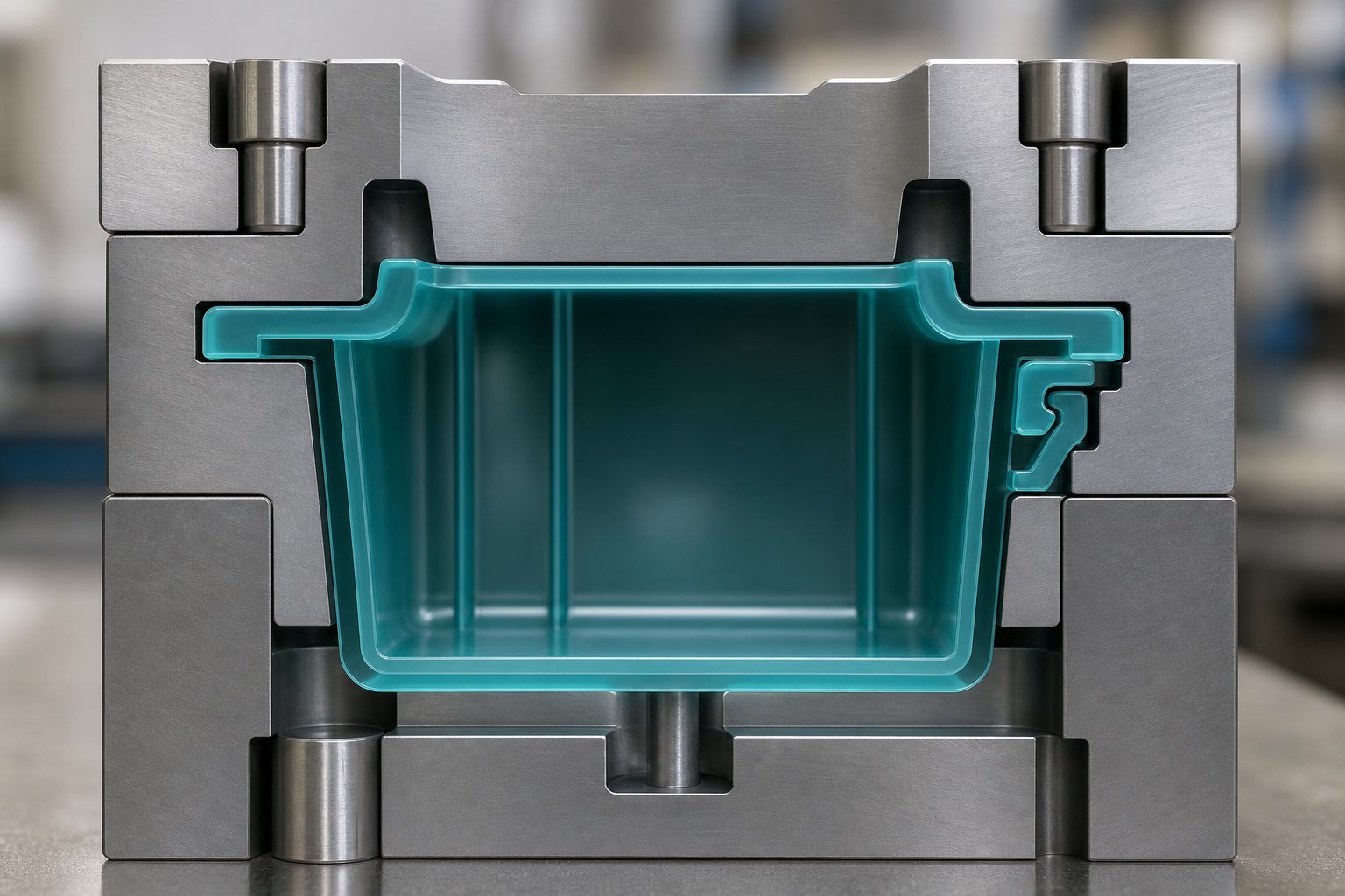
Here is a mistake that costs teams thousands of dollars and weeks of schedule: designing a part in isolation, then shopping for a process to produce it. The geometry you draw on screen - its wall thickness, draft angles, undercuts, and tolerance demands - is not a passive input handed to manufacturing. It is an active filter that eliminates certain processes entirely, inflates costs on others, and makes one or two options clearly superior. When manufacturing plastic components, the part design is the process selection decision, whether the engineering team realizes it or not.
Wall Thickness, Draft Angles, and Undercuts
If there is one rule that applies across nearly every plastic processing method, it is this: keep wall thickness as uniform as possible. Non-uniform walls create uneven cooling, which leads to sink marks, warpage, and internal stress. In injection molding, Protolabs recommends that secondary features like ribs and bosses should be no less than 40 to 60 percent the thickness of adjacent walls to avoid sink on the visible surface. Different materials also have their own recommended thickness ranges - ABS typically runs 0.045 to 0.140 inches, polycarbonate 0.040 to 0.150 inches, and polypropylene 0.025 to 0.150 inches.
Thermoforming shares the uniform-wall principle but adds a twist: because the sheet stretches over or into a mold, corners and deep draws thin out naturally, so starting sheet gauge must account for that material redistribution. Rotational molding, by contrast, builds wall thickness through powder deposition, making it surprisingly consistent for large hollow parts but difficult to control precisely at specific locations.
Draft angles - the slight taper applied to vertical surfaces so the part releases cleanly from the mold - vary by method. Injection molding typically requires one to two degrees per side, with textured surfaces demanding more. Thermoforming often needs three to five degrees because the part must release from a single-sided tool without mechanical ejection. Compression molding is more forgiving on draft but less forgiving on geometric complexity.
Undercuts are where tooling costs escalate fast. An undercut is any feature that prevents the part from being pulled straight out of the mold - a snap-fit hook, a side hole, or an internal groove. Injection molding can handle undercuts using side-actions and lifters, but each one adds cost and complexity to the tool. As DFMA's process selection framework notes, undercuts can be molded in injection tooling, but they typically require secondary machining if the part is cast. For thermoforming and compression molding, significant undercuts may rule out the process altogether.
Tolerances and Surface Finish Requirements
How precise does the finished part actually need to be? Your answer to this question directly shapes which processes stay on the shortlist and which fall off.
Injection molding delivers the tightest tolerances of any high-volume plastic process - typically holding dimensions within a few thousandths of an inch on well-designed tooling. This is why it dominates applications like medical device housings, electrical connectors, and precision assemblies where plastic parts manufacturing demands interchangeability across millions of units.
Extrusion and thermoforming occupy the middle ground. Extruded profiles hold cross-sectional dimensions well, but cut-length tolerances and post-cooling dimensional changes introduce variability. Thermoformed parts achieve reasonable accuracy, but visible draft angles and material thinning at draw points limit how tightly you can specify critical dimensions.
Rotational molding sits at the loosest end of the tolerance spectrum. Wall thickness can vary by 10 to 20 percent across a single part, and overall dimensions are less repeatable than any molding method. If your design requires tight fits or mating surfaces, rotational molding will need secondary machining - adding cost and cycle time.
Surface finish tells a similar story. Injection molding can produce high-gloss, matte, or custom-textured surfaces directly from the mold by specifying the appropriate steel finish. Thermoforming reproduces the tool surface on one side but leaves the non-tool side uncontrolled. Rotational molding produces a slightly pebbly surface by nature, limiting its suitability for cosmetic applications without secondary finishing. If a high-gloss, Class A surface is non-negotiable, your process options narrow significantly before you even consider volume or cost.
Volume, Geometry, and Cost as Decision Drivers
Wall thickness, tolerances, and surface finish are design-driven constraints. But three additional factors - production volume, geometric complexity, and budget - complete the picture. Together, all five criteria form a practical checklist for plastic component manufacturing decisions. Walk through them in order:
- Define part geometry complexity. Is the shape solid or hollow? Does it include undercuts, internal features, or thin-walled sections? Complex 3D geometry points toward injection molding; large hollow forms point toward blow or rotational molding; constant cross-sections point toward extrusion.
- Specify material requirements. Which polymer tier - commodity, engineering, or high-performance - does the application demand? Does it require fillers, flame retardants, or specific FDA or UL compliance? Material narrows both the process and equipment options, as the material selection framework earlier in this article demonstrated.
- Estimate production volume. A few hundred prototypes, 10,000 units per year, or millions? DFMA's volume-based selection matrix shows that machining is most economical from 1 to 10,000 units, injection molding becomes cost-competitive at 5,000 to 10,000 units and dominates at higher volumes, while thermoforming fills the gap for moderate runs where tooling investment must stay low.
- Set tolerance and finish requirements. Define the tightest dimensional tolerance and the required surface quality. Over-specifying tolerances inflates cost disproportionately - loosening them where possible is consistently cited as one of the highest-impact design-for-manufacturing opportunities.
- Evaluate tooling budget constraints. Steel injection molds represent a significant capital investment; aluminum thermoforming tools or rotational molds cost a fraction of that amount. If your production of plastic parts is a short-run program, a lower-cost tool that delivers acceptable quality may outperform a premium tool that never amortizes its investment.
The best process is the one that meets all five criteria at the lowest total cost of ownership - not just the lowest per-unit price.
This distinction matters more than most teams realize. A process with a lower piece price but higher tooling cost, longer lead time, and additional post-processing may actually cost more over the life of the program than an alternative with slightly higher unit cost but faster setup and fewer secondary steps. Manufacturing of plastic components rewards systems-level thinking, not line-item optimization.
Design decisions lock in process options - but they also determine how much work remains after the part exits the mold, die, or form. Trimming, machining, surface treatment, and assembly operations all add cost and time, and in some cases they reveal that the primary process was the wrong choice from the start.
Post-Processing Operations That Complete the Product
A part exits the mold, cools on the conveyor, or drops from the die - and it is not finished. Gates need trimming, surfaces need treating, subcomponents need joining, and in many cases features that the primary process could not produce still need to be created. So what is plastic fabrication in its fullest sense? It is not just shaping resin into geometry. It is every operation - primary and secondary - required to turn a raw molded or extruded form into a component ready for its end-use environment. Post-processing is where that transformation completes, and overlooking it during project planning is one of the fastest paths to budget overruns and missed ship dates.
Machining, Trimming, and Secondary Shaping
Some features are simply impractical to produce during the primary forming step. A precision bore that must hold tight tolerances across mating assemblies. A slot machined into a thick boss. A routed edge on a thermoformed panel. These requirements pull machined operations into the plastic fabrication process as a planned, value-adding stage rather than an afterthought.
The most common secondary shaping operations include:
- CNC machining: Milling, drilling, and plastic turning operations refine molded or extruded parts to final dimensions. This is especially practical for low-volume production runs, prototype parts, or features with tolerances tighter than the primary process can reliably achieve.
- Trimming: Gate vestiges from injection molding, flash along parting lines, and edge scrap from thermoforming all require removal. Methods range from manual clipping and pneumatic trimming presses to robotic routers that follow programmed paths at high speed.
- Routing and die cutting: Large thermoformed panels and extruded sheets often need perimeter trimming, hole cutting, or profile routing to reach their final outline. Five-axis CNC routers handle complex contours, while the plastic stamping process uses shaped dies to blanch or punch features from flat or formed sheet stock at high speed - particularly in packaging and automotive trim applications.
Each of these operations adds fixture design, machine time, and inspection steps. As HingTung's manufacturing team notes, machining can reduce injection mold complexity in some cases, but the tradeoff is a higher per-part cost that compounds rapidly at volume. The decision to machine a feature rather than mold it should always be evaluated against the production run length.
Surface Treatment, Joining, and Assembly
Beyond dimensional refinement, most products require finishing steps that improve appearance, enable assembly, or add functional protection. These operations group naturally into four categories:
- Material removal: Sanding, bead blasting, deburring, and polishing to eliminate tool marks, improve surface texture, or prepare the substrate for coating adhesion.
- Surface treatment: Painting, UV coating, plating (electroless nickel, chrome), and pad or screen printing for color, branding, and environmental protection. Materials like PP and PE have low surface energy, so plasma or flame treatment is often required before paint or ink will bond reliably.
- Joining: Ultrasonic welding, hot plate welding, vibration welding, laser welding, spin welding, adhesive bonding, and mechanical fastening (screws, snap-fits, threaded inserts). Plastic welding methods like ultrasonic and hot plate techniques create permanent, high-strength bonds without additional fasteners, making them standard in electronic housings, sealed enclosures, and medical devices. Each method has material and geometry constraints - ultrasonic welding demands compatible thermoplastics and a properly designed energy director, while hot plate welding suits larger joint areas but cannot handle parts thinner than roughly 2.5 mm.
- Decoration: Laser marking for traceability codes, in-mold labeling for packaging, and heat transfer printing for complex multicolor graphics. The decoration method must be matched to the polymer: a mark that looks sharp on ABS may fade on chemically resistant polyethylene without surface pretreatment.
In high-volume production, many of these steps run in automated cells synchronized with the molding or extrusion cycle. Finishing operations can represent a significant share of total manufacturing cost, particularly for consumer-facing products where cosmetic quality drives rejection rates. Integrating post-processing planning into the project timeline - before mold design begins - avoids the costly surprises that arise when gate locations, ejector marks, or weld lines interfere with printing zones or bonding surfaces.
When Post-Processing Adds Value vs. When It Signals Process Mismatch
Here is the critical-thinking question most teams skip: is the post-processing you are performing adding genuine value, or is it compensating for a poorly chosen primary process?
Some secondary operations are inherently value-adding. A laser-marked serial number enables traceability. An ultrasonic weld seals an IP-rated enclosure. A plastic stamping process step punches ventilation slots into a thermoformed panel far more efficiently than molding each slot individually. These are planned steps that improve the product and would be necessary regardless of which forming method you selected.
Other post-processing steps are red flags. Imagine you are CNC machining multiple precision features into every injection-molded part because the mold was designed without those features to save tooling cost. At 500 units, that trade-off might make sense. At 50,000 units, the accumulated machining time, fixture costs, and scrap from secondary handling likely exceed what a more complex mold would have cost. Similarly, if you are sanding every thermoformed part to remove witness lines that a better tool finish would eliminate, you are spending labor dollars to patch a tooling decision.
A practical rule of thumb: if post-processing consumes more than 15 to 20 percent of your total part cost or adds significant cycle time to every unit, revisit the five-step process selection checklist from the previous section. Ask whether a different primary process, a redesigned part, or an upgraded tool could eliminate or simplify those secondary steps. The cheapest post-processing operation is the one you engineered out of the workflow entirely.
Treat excessive post-processing as a diagnostic signal, not just a cost line - it often points back to a mismatch between part design, material choice, and primary forming method.
This diagnostic mindset connects directly to a broader question every operation faces: how do you build a production system that minimizes waste, controls costs, and stays resilient as sustainability pressures and material economics continue to evolve?
Sustainability, Cost Economics, and Next Steps for Your Operation
Every parameter tweak, material swap, and equipment upgrade discussed throughout this article shares a common thread: they all affect how much energy, material, and money your operation consumes per finished part. In the plastics processing industry, sustainability is no longer a corporate brochure talking point - it is a cost lever. The teams that treat waste reduction and energy efficiency as engineering problems rather than PR exercises are the ones lowering their per-unit costs while competitors absorb rising resin prices and tightening regulations.
Energy Efficiency and Waste Reduction Strategies
Where does energy actually go in a typical plastic manufacturing process? The largest share flows into melting and conveying resin - which puts the screw, barrel, and heater system at the center of any efficiency conversation. A properly designed screw optimized for the specific resin and application can dramatically reduce energy consumption. As Turner Group's sustainability analysis illustrates, a general-purpose three-zone screw will melt and convey material, but it is not engineered for your particular resin, colorant, or shot utilization. The result? Operators compensate with higher back pressure, faster screw RPM, and elevated barrel temperatures - all of which pile on energy costs and increase scrap rates without solving the root cause.
Beyond screw optimization, three other strategies deliver measurable returns:
- Regrind integration: Reprocessing runners, sprues, and edge trim back into the production stream reduces virgin resin purchases. The key is controlling regrind ratios and particle size to maintain consistent melt behavior.
- Closed-loop cooling systems: Recirculating coolant rather than running single-pass water cuts utility costs and stabilizes mold or downstream temperatures, improving dimensional consistency at the same time.
- Cycle time optimization: Shaving even a few seconds off each injection molding cycle - through better cooling channel design, optimized packing profiles, or faster mold actions - compounds into significant energy and throughput gains across millions of cycles.
Each of these levers connects to decisions made earlier in the workflow: material selection, part design, and parameter tuning. Sustainability is not a separate initiative bolted on at the end - it is embedded in every upstream choice.
Recycling Integration and Circular Economy Approaches
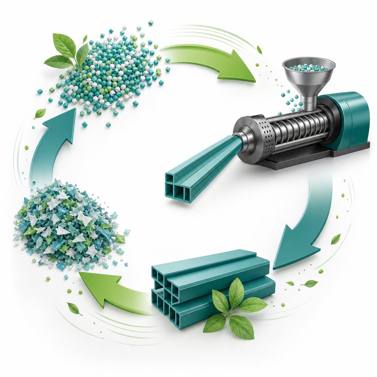
The plastic product manufacturing industry is moving away from the linear "take, make, dispose" model. Driven by Extended Producer Responsibility laws in states like California, Colorado, and Oregon, rising virgin resin costs, and supply chain volatility, manufacturers are building circular loops directly into their operations. The concept is straightforward: keep plastic in productive use for as long as possible by grinding scrap on-site, re-pelletizing it through extrusion, and feeding it back into production.
The execution, however, is anything but simple. Post-consumer and post-industrial recyclate introduces variability that virgin resin does not. Recycled feedstock varies in composition, melt flow index, and contamination levels from batch to batch, creating processing challenges that range from inconsistent mold filling to degraded mechanical properties in finished parts. Additives like compatibilizers, MFI modifiers, and chain extenders help stabilize these inconsistent streams, but they cannot compensate for equipment that is already struggling.
This is where equipment condition becomes a sustainability issue, not just a maintenance one. Recycled feedstocks are often more abrasive and corrosive than virgin materials. Screw barrels that are already worn from processing standard resins will degrade faster and produce worse results when fed post-consumer recyclate. Maintaining tight clearances between screw flights and barrel walls is essential to achieving the melt homogeneity that variable feedstocks demand. Worn components increase leakage flow, raise melt temperatures, and force operators to compensate with higher energy input - undermining the very efficiency gains that recycling is supposed to deliver.
Manufacturing plastic from recycled sources is technically viable and increasingly economical, but only when the processing equipment - particularly the screw barrel system - is engineered and maintained for the job.
Building a Resilient Plastic Processing Operation
This article has walked through the entire polymer processing chain, from raw material chemistry to post-processing and finishing. The through-line across every section is the same: informed decisions at each stage compound into lower costs, higher quality, and greater operational flexibility. Here are the core takeaways to carry forward:
- Match process to part design: Use the five-step checklist - geometry, material, volume, tolerances, and tooling budget - to select the forming method that delivers the lowest total cost of ownership.
- Select materials systematically: Understand how polymer tier, melt flow behavior, and additive packages constrain which processes and equipment are viable before committing to tooling.
- Optimize parameters continuously: Temperature, pressure, and speed interact with cooling to determine part quality. Systematic tuning reduces scrap, energy consumption, and cycle time simultaneously.
- Maintain critical equipment proactively: Worn screws and barrels silently erode output quality, energy efficiency, and the ability to process demanding materials - including the recycled feedstocks that the polymer processing industry increasingly relies on.
- Design for sustainability from the start: Mono-material designs, regrind-friendly formulations, and efficient equipment choices reduce waste and position your operation for tightening regulations.
For extrusion-focused operations - whether you are running pipe, profile, film, sheet, WPC, or granulation lines - the screw barrel system is the single component with the greatest influence on melt quality, energy efficiency, and your ability to process both virgin and recycled materials reliably. If this article helped you identify extrusion as your primary process, or if your current line is showing signs of wear-related performance decline, NANHAIYA's plastic extruder machine and screw barrel support page provides a practical next step: component-level guidance for sourcing replacement screw barrels, exploring custom extrusion configurations, and matching barrel metallurgy to your specific resin and application demands across pipe, profile, film, sheet, WPC, and granulation equipment.
The plastic products manufacturing landscape will keep evolving - new polymers, stricter environmental mandates, and rising expectations for recycled content will reshape the rules. But the fundamentals laid out here will not change. The teams that understand their materials, choose their processes deliberately, optimize their parameters rigorously, and maintain their equipment proactively are the ones that will thrive regardless of what the market throws at them. That is what a resilient operation looks like.
Frequently Asked Questions About Plastic Processing
1. What are the main types of plastic processing methods?
The main types include injection molding for complex high-volume solid parts, blow molding for hollow products like bottles and tanks, extrusion for continuous profiles such as pipes and films, compression molding for thermoset materials, thermoforming for sheet-based packaging and panels, and rotational molding for large seamless hollow parts. Each method suits different part geometries, production volumes, and material requirements, so choosing the right one depends on matching your specific design, budget, and performance criteria.
2. How do you choose the right plastic processing method for a specific part?
A systematic five-step approach works best. First, define part geometry complexity - solid, hollow, or constant cross-section. Second, specify material requirements including polymer tier and additive needs. Third, estimate production volume, since tooling costs amortize differently across run lengths. Fourth, set tolerance and surface finish requirements, as injection molding delivers the tightest precision while rotational molding offers the loosest. Fifth, evaluate your tooling budget. The goal is finding the method that meets all five criteria at the lowest total cost of ownership, not just the lowest per-unit price.
3. What is the difference between thermoplastics and thermosets in processing?
Thermoplastics can be reheated, melted, and reshaped multiple times, making them compatible with injection molding, extrusion, blow molding, and thermoforming. They are also mechanically recyclable. Thermosets, on the other hand, undergo irreversible chemical cross-linking during curing, which means they cannot be re-melted once set. This limits thermosets to processes like compression molding, transfer molding, and reaction injection molding. Thermosets offer superior heat resistance and structural rigidity, while thermoplastics provide greater design flexibility and recyclability.
4. Why is screw and barrel condition critical in plastic extrusion?
The screw and barrel system is the heart of any extrusion line. Screw geometry - including L/D ratio, compression ratio, and flight depth - directly controls melt quality, output rate, and energy efficiency. When barrel wear increases the radial clearance between screw flights and the barrel wall, leakage flow rises, output drops, and melt temperature climbs uncontrollably. This leads to defects like melt fracture, gels, and dimensional inconsistency. Maintaining tight screw-barrel clearances is especially important when processing abrasive filled compounds or recycled feedstocks. Suppliers like NANHAIYA offer replacement screw barrels and custom configurations at nhyscrew.com for pipe, profile, film, sheet, WPC, and granulation equipment.
5. How does recycled plastic feedstock affect the processing workflow?
Recycled feedstock introduces batch-to-batch variability in composition, melt flow index, and contamination levels that virgin resin does not have. This can cause inconsistent mold filling, degraded mechanical properties, and increased equipment wear since recyclate is often more abrasive and corrosive than virgin materials. Processors compensate by using compatibilizers, MFI modifiers, and chain extenders. However, maintaining well-conditioned processing equipment - particularly screw barrels with tight clearances - is essential. Worn components amplify the challenges of variable feedstocks by increasing leakage flow and raising melt temperatures, ultimately undermining the cost and environmental benefits recycling is supposed to deliver.
Written by
Nanhaiya Technical Team
Zhoushan Nanhaiya Plastic Machinery Co., Ltd.
The Nanhaiya technical team supports screw and barrel manufacturing projects through application review, technical communication, custom manufacturing coordination, and production and quality control.
Discuss Your Application
Related Articles
More insights on screw barrel technology and plastics processing.

What Nobody Tells You About Screw Barrel For Plastic Machine Design
Oct 10, 2026
Learn how screw barrel for plastic machine design affects melt quality, throughput, and wear life. Covers geometry, resin matching, troubleshooting, and sourcing.
Read Article
Single Screw Extruder for Sheet: Stop Guessing, Start Specifying
Oct 9, 2026
Learn how to specify a single screw extruder for sheet production. Covers screw geometry, resin-specific processing, troubleshooting, and maintenance best practices.
Read Article
PE Pipe Extruder Machine: What Datasheets Won't Tell You
Oct 9, 2026
Learn how a PE pipe extruder machine works, key specs explained, material grade selection, maintenance tips, and buyer guidance beyond the datasheet.
Read ArticleLooking for something else?
Search by material, symptom or product and jump straight to the relevant page.
These are navigation suggestions based on keyword matching — not a quotation, not a delivery commitment, and not a substitute for engineering review. Final specification is confirmed by our engineers against your drawings and processed material.
Need help with screw barrel selection?
Share your machine model, processed material and application. Our team can help with pricing and technical support.