

塑料管道生产线究竟做什么
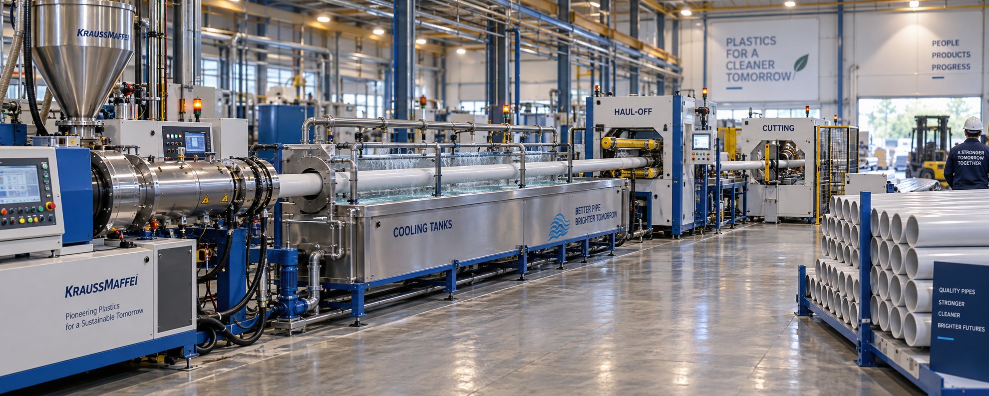
想象一下,一袋聚合物树脂从工厂车间的一端进入,另一端则涌出一堆尺寸精准、随时可以发货的管道。这种转变正是塑料管道生产线的功劳——一个完全集成的机器系统,它将原材料聚合物熔化,将其成型为管状,冷却固化,然后根据精确的直径、壁厚和长度规格切割和加工每根管道。系统中的每个组件都将其输出直接输送到下一个组件,从而形成一个连续、高度自动化的生产流程。
定义塑料管道生产线
从本质上讲,管道生产线并非一台单一的机器,而是一系列协同工作的专用设备。原材料(通常以颗粒或粉末形式)进入生产线,最终产出成品管道。在这两个终点之间,树脂依次经过进料和计量系统、挤出机(用于熔化和均质聚合物)、模头(用于将熔融塑料成型为管材)、真空校准和冷却槽(用于确保尺寸精度)、牵引装置(用于维持稳定的生产线速度)以及切割系统(用于按预设长度切割管道)。每个工位的产量必须与其他工位保持一致。如果任何一个工位的产量下降,整条生产线的速度都会随之降低。
塑料管道生产线不是一台单独的机器,而是一个同步系统,其整体产量受限于其中最慢的部件。
这种系统层面的视角很重要,因为采购决策、故障排除和产能规划都取决于了解这些组件如何相互作用,而不仅仅是了解每个组件单独执行的操作。
本指南为何涵盖所有聚合物类型
搜索有关塑料管道制造的信息,你会发现一个规律:几乎所有排名靠前的资源都只关注PVC。这给使用HDPE、PP、PPR、PEX、PE-RT或ABS的生产工程师和采购经理造成了巨大的信息空白。事实上,管道生产线可以针对这些聚合物中的任何一种进行配置,但每种材料都需要不同的挤出机结构、螺杆几何形状、加工温度和下游设备设置。一条针对硬质PVC优化的生产线与一条为生产高密度聚乙烯或交联聚乙烯而设计的生产线在外观和运行方式上截然不同。
This guide takes a cross-material approach. Whether you are evaluating a capital investment in a new line, comparing supplier configurations, or diagnosing performance issues on an existing setup, every section ahead applies across the full spectrum of pipe-grade polymers. The differences between materials - and how those differences reshape equipment selection - are addressed head-on rather than ignored.
That cross-material scope starts with the extrusion process itself, where the journey from raw resin to molten polymer reveals exactly why screw design, barrel heating, and die geometry must be matched to the target material from the very first stage.
How Plastic Pipes Are Made Step by Step
So how are plastic pipes made, exactly? The pipe extrusion process follows a logical sequence of nine stages - each one building on the previous. Whether the line runs PVC, HDPE, PP, or a specialty polymer, the fundamental flow remains the same. Material-specific differences (covered later in this guide) adjust parameters within each stage rather than rearranging the sequence itself.
Here is the complete process at a glance before we break each stage down:
- Raw material preparation - drying, mixing, compounding, and additive dosing
- Feeding - loss-in-weight or volumetric feeders delivering material into the extruder
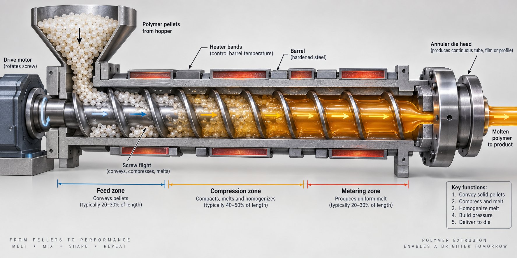
- Plasticization - the screw rotates inside a heated barrel, melting and homogenizing the polymer
- Die forming - molten polymer is shaped into a tubular profile through an annular die head
- Vacuum calibration - the still-soft pipe is pulled through a vacuum sizing sleeve to set outer diameter and roundness
- Cooling - spray or immersion cooling tanks solidify the pipe
- Haul-off - caterpillar or belt pullers maintain constant line speed and pipe tension
- Cutting - planetary or chipless saws cut to programmed lengths
- Socketing/belling and stacking - final finishing and organization for shipment
From Raw Resin to Molten Polymer
Every extruded pipe manufacturing run starts with raw material preparation. Polymer pellets or powder are dried, blended with additives - such as UV stabilizers, color masterbatch, impact modifiers, or lubricants - and compounded into a homogeneous mixture. Moisture control at this stage is critical. Even small traces of water in polyolefin resins can cause bubbles, surface roughness, and weakened mechanical properties in the finished pipe.
The prepared material then enters the extruder through a feeding system. Loss-in-weight feeders measure material gravimetrically, delivering precise and consistent dosing regardless of bulk density changes. Volumetric feeders offer a simpler, lower-cost alternative but are less accurate when material characteristics vary between batches.
Inside the extruder barrel, the real transformation begins. The rotating screw conveys pellets from a feed zone through a compression (transition) zone and into a metering zone. Barrel heaters raise the temperature gradually, while mechanical shear generated by the screw contributes significant additional heat. The interplay between screw geometry - specifically the channel depth, compression ratio, and flight design - and the barrel's heating zone configuration determines melt quality. A screw with the wrong L/D ratio or compression profile for the target polymer can produce an uneven melt riddled with unmelted particles, thermal degradation, or excessive pressure buildup. Typical processing temperatures range from 160-200 degrees C for rigid PVC up to 200-240 degrees C for polypropylene, depending on the grade.
Shaping, Sizing, and Solidification
The homogenized melt exits the extruder and enters the die head, where the extrusion of pipes truly takes shape. A spiral mandrel die distributes the molten polymer evenly around an annular gap, forming a tubular profile. The die gap sets the initial wall thickness, while the mandrel determines the inner diameter. Temperature stability across the die is essential - cold spots trigger premature solidification and surface defects, while hot spots degrade the polymer and reduce mechanical strength.
Immediately after leaving the die, the hot, still-pliable pipe enters a vacuum calibration tank. A precision-machined sizing sleeve, typically made of bronze for its balance of durability and thermal conductivity, receives the pipe. Vacuum pressure - generally ranging from -0.2 to -0.8 bar depending on pipe size and material - pulls the outer surface firmly against the sleeve, locking in the target outer diameter and roundness. Cooling water circulates through and around the sleeve to begin removing heat from the pipe wall.
The pipe then passes through additional spray or immersion cooling tanks that bring it down to a handling temperature. Cooling rate matters far more than you might expect: too fast, and internal stresses lock into the pipe wall, causing warping or reduced impact resistance down the road. Too slow, and line speed drops along with your output. Multi-section cooling tanks with independent temperature control offer the best balance between quality and throughput. The total cooling length required increases with pipe diameter - large-diameter pipes may need significantly longer tank runs than small-diameter products.
Haul-Off, Cutting, and Finishing
With the pipe fully solidified, the haul-off unit takes over. Caterpillar-style pullers - using rubber or metal belts that grip the pipe surface - maintain a constant pulling speed synchronized with extruder output. This synchronization is the heartbeat of the pipe extrusion process. If haul-off speed runs even slightly faster than the extrusion rate, the wall thins. Slightly slower, and the wall thickens or the pipe buckles between the die and the calibration tank. Modern lines use closed-loop control systems to maintain this relationship automatically.
At programmed intervals, the cutting system activates. Planetary saws rotate around the pipe circumference, producing clean cuts on larger diameters without stopping the line. Chipless cutting systems use a blade that compresses and parts the material rather than sawing through it - ideal for smaller, thinner-walled pipes where dust-free cuts prevent contamination.
Depending on the application, cut pipes may proceed to a socketing or belling machine that heats one end and forms an expanded socket for push-fit or gasket joints. Inline socketing happens without removing the pipe from the production flow, while offline units handle belling as a separate operation. Finally, automatic stacking and bundling systems organize the finished pipes for inspection and shipment, reducing both labor costs and surface damage from manual handling.
Each of these nine stages relies on equipment precisely specified for the job. The extruder architecture, die design, calibration tooling, and every downstream component must be matched not only to each other but to the specific polymer being processed - a deeper look at exactly what each piece of equipment contributes and how its specifications shape overall line performance.
Every Component in a Pipe Production Line Explained
Knowing the nine-step process is one thing. Understanding the actual machines that execute each step - and how their specifications ripple across the entire line - is what separates informed buyers from ones stuck with mismatched plastic pipe equipment. This section breaks down every major component, starting with the heart of any line: the extruder.
Extruder Types and Their Applications
The extruder does the heaviest lifting in any pipe production line. It melts, mixes, and pressurizes the polymer before pushing it toward the die. Three main architectures dominate the market, and choosing the wrong one for your target polymer creates problems that no amount of downstream adjustment can fix.
The single-screw extruder is the workhorse for polyolefin pipe lines - PE, PP, and flexible PVC. A single rotating screw inside a heated barrel conveys and melts the polymer through friction, shear, and conducted heat. It offers excellent cost-efficiency, simpler maintenance, and reliable output when processing pre-compounded pellets. Grooved-feed-barrel variants further improve conveying stability for HDPE and PP resins.
The conical twin-screw extruder is the dominant choice for rigid PVC. Two tapered, intermeshing screws provide superior mixing and gentler shear - critical for a heat-sensitive material like PVC-U that degrades quickly under excessive temperature. Conical twin-screw designs can process PVC dry blends directly, eliminating the separate pelletizing step and reducing total production cost over the line's lifecycle.
The parallel twin-screw extruder features two same-diameter screws running side by side. It handles high-filler formulations and specialty compounds where intensive compounding and strong pressure generation are needed. Its higher initial cost limits adoption to specialized applications.
Screw geometry has to match the target polymer. The L/D ratio (screw length divided by diameter) controls residence time and melt homogeneity. Compression ratio determines how aggressively the material is compacted. Barrel zone configuration - the number and arrangement of independent heating and cooling segments - must align with the polymer's thermal profile. Pair the wrong screw design with the wrong barrel, and you get uneven melt temperature, degradation, or pressure instability.
| Extruder Type | Best-Suited Polymers | Typical L/D Ratio Range | Relative Cost | Key Advantage |
|---|---|---|---|---|
| Single-Screw | PE, PP, Flexible PVC, PEX, PE-RT | 25:1 - 36:1 | Low - Medium | Cost-efficiency, simple maintenance |
| Conical Twin-Screw | Rigid PVC (PVC-U, PVC-O, PVC-C) | Conical (equivalent ~22:1 - 28:1) | Medium - High | Superior shear control for heat-sensitive PVC |
| Parallel Twin-Screw | High-filler PVC, specialty compounds | 24:1 - 40:1 | High | Intensive mixing, high pressure generation |
What often gets overlooked is the barrel itself. The barrel's bore finish, internal hardness, and heating zone layout directly influence melt quality and throughput consistency. A worn or poorly specified barrel allows backflow along the screw flights, reducing output and creating temperature inconsistencies. For single-screw pipe extrusion lines, sourcing a precision-engineered barrel is just as important as selecting the right screw geometry. Suppliers like NANHAIYA specialize in custom and replacement single screw barrels designed specifically for pipe extrusion applications, offering material grades and bore specifications tailored to the polymer being processed - whether that is HDPE, PP, or flexible PVC.
Die Heads and Vacuum Calibration Systems
Once the extruder delivers a stable, homogenized melt, the die head shapes it. Two main designs serve pipe applications:
- Spiral mandrel dies use helical flow channels to distribute the melt evenly around the annular gap. They minimize weld lines - the seams where separate melt streams rejoin - and are the standard choice for most PVC pipe extrusion lines and polyolefin pipe production.
- Crosshead dies redirect the melt flow at a 90-degree angle to the extruder axis. They are used primarily for coating applications, cable jacketing, or specialized configurations where the pipe exits perpendicular to the screw axis.
Immediately downstream, the vacuum calibration system determines whether your pipe meets dimensional tolerances or gets rejected. The sizing sleeve - typically bronze or stainless steel - must be machined to tight tolerances matching the target outer diameter. Vacuum pressure pulls the soft pipe wall against the sleeve surface, setting roundness and OD. Too little vacuum allows the pipe to sag or go oval. Too much can cause surface drag marks or even collapse thinner walls. The interplay between sleeve material, surface finish, and vacuum level needs careful calibration for each pipe size and polymer type.
Auxiliary and Downstream Equipment
The extruder and die get most of the attention, but the downstream equipment determines whether a PVC pipe making machine - or any pipe line - actually delivers consistent, sellable product.
- Loss-in-weight feeders gravimetrically meter raw material into the extruder, maintaining precise feed rates even when bulk density varies between batches. Volumetric feeders cost less but introduce feed variation that shows up as wall thickness inconsistency.
- Cooling tanks come in spray and immersion configurations. Spray tanks offer faster initial cooling and are common for smaller diameters. Immersion tanks provide uniform, deep cooling for larger pipes. The total cooling tank length must match line speed - undersized cooling is one of the most common bottlenecks in production capacity.
- Haul-off units use caterpillar belts or rubber-padded tracks to pull the pipe at a speed synchronized with the extruder. Multi-belt caterpillar designs handle large-diameter and heavy-wall pipes, while simpler belt pullers suffice for smaller products. Grip pressure must be tuned to avoid surface marking without allowing slippage.
- Cutting systems split into two main categories. Planetary saws orbit around the pipe for clean, dust-free cuts on medium and large diameters. Chipless cutters compress and part the pipe wall - faster and ideal for small-diameter, thin-wall products, though limited by wall thickness capacity.
Every one of these components has a maximum throughput. If your extruder pushes 500 kg/hr but your cooling section can only handle 350 kg/hr, the line runs at 350 kg/hr. Balancing capacity across every station is the single most impactful factor in getting full value from your plastic pipe equipment investment.
Equipment architecture, however, is only half the story. The same machine PVC producers rely on looks quite different when configured for HDPE, PP, or cross-linked polyethylene - and understanding those material-specific configurations is where most buyers' research falls short.
Production Line Configurations for Every Pipe Material
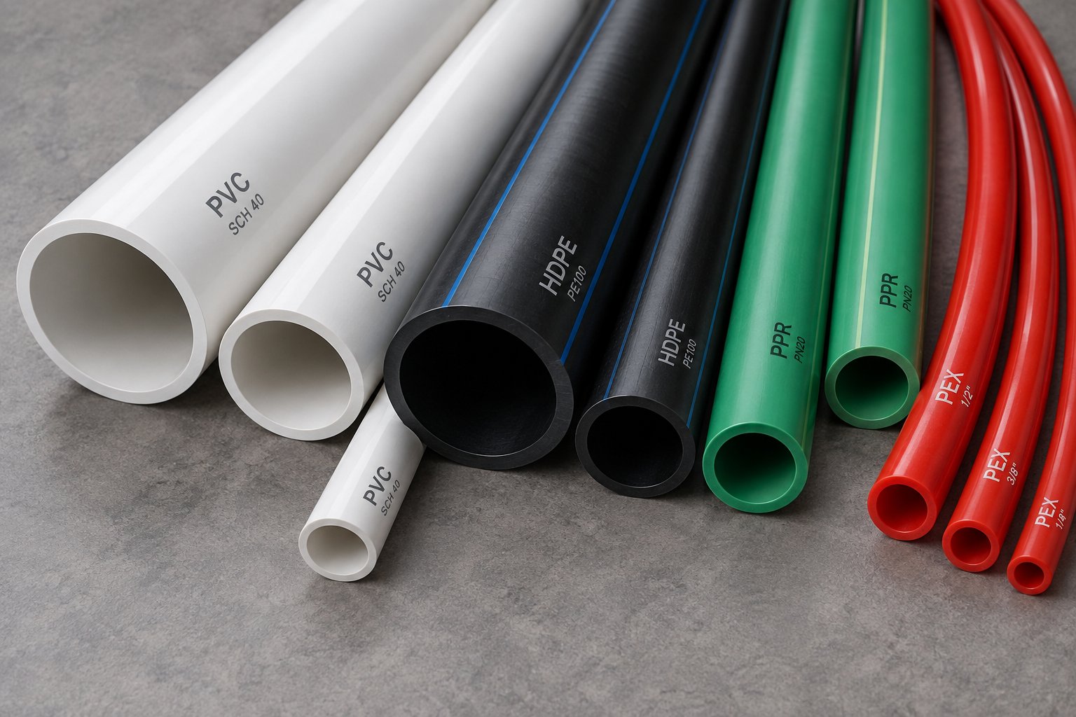
Here is where most online resources stop being useful. They explain pipe extrusion as if PVC were the only polymer on the planet, leaving engineers and procurement managers working with polyolefins or specialty materials to piece together scattered fragments of information. The reality? Each polymer family demands a fundamentally different line configuration - different extruder architecture, different thermal profiles, different additive strategies, and different downstream handling. Choosing the wrong setup does not just reduce efficiency; it can make consistent production nearly impossible.
Think of this section as your material-by-material reference guide. Whether you are evaluating a PVC pipe production line, specifying a polyethylene system, or exploring specialty options like PEX, the configuration details below will clarify exactly what each polymer requires.
PVC Pipe Lines - Rigid and Flexible Configurations
PVC pipes manufacturing accounts for the largest share of global plastic pipe output, and for good reason. Polyvinyl chloride delivers excellent chemical resistance, mechanical strength, and long service life at a competitive price point. But how is PVC made into pipe? The answer starts with understanding that PVC is uniquely heat-sensitive. Unlike PE or PP, it does not melt into a free-flowing liquid. Instead, it transitions into a gelled, elastic-plastic state that demands careful shear and temperature management throughout the entire extrusion process.
Rigid PVC - technically called PVC-U (unplasticized) - is the dominant material for water supply, drainage, and conduit applications. The conical twin-screw extruder is the industry-standard choice for PVC-U pipe extrusion because its tapered, intermeshing screws deliver the controlled, low-shear mixing that this polymer requires. Excessive shear generates heat that triggers thermal degradation, releasing hydrochloric acid and causing discoloration, brittleness, and ultimately product failure.
Resin selection is the foundation of any rigid PVC pipe line. PVC resins are graded by K-value, which reflects molecular weight:
- K57-K60: Lower viscosity grades suited for injection molding and thin-wall profiles - rarely used for pipe
- K67: The general-purpose workhorse for most PVC pipe mfg, balancing processability with mechanical performance
- K70: Higher molecular weight grades chosen for pressure-rated pipe applications where long-term hydrostatic strength is critical
Selecting the wrong K-value creates a cascade of processing headaches. A K70 resin run on a line optimized for K67 can produce excessive extruder torque and incomplete fusion, while a K60 grade may lack the melt strength needed for larger pipe diameters.
Beyond the resin itself, rigid PVC compound formulation involves a precise balance of thermal stabilizers (calcium-zinc or tin-based systems that prevent degradation during processing), internal and external lubricants that control friction between the melt and metal surfaces, calcium carbonate fillers for stiffness and cost reduction, and impact modifiers like CPE or acrylic compounds that improve toughness. An imbalanced lubricant system alone can cause sharkskin surface texture, unstable melt pressure, and poor dimensional control.
Rigid PVC pipe lines typically reference ISO 1452 / EN 1452 for pressure water pipes and ASTM D2241 for general PVC water pipe in North American markets. Processing temperatures run in the 160-200 degrees C range, deliberately kept low to avoid thermal degradation.
Flexible PVC lines differ significantly. They use plasticizers - typically phthalate or non-phthalate compounds - that soften the polymer and allow processing on single-screw extruders. The resulting pipes serve applications like garden hoses, medical tubing, and flexible conduit, where rigidity would be a disadvantage.
HDPE, MDPE, and PP Pipe Lines
Polyolefin pipe lines operate under a completely different set of rules. HDPE, MDPE, and polypropylene are semicrystalline thermoplastics that melt into a true viscous flow - a stark contrast to PVC's gelled state. This difference reshapes the entire line configuration from the extruder barrel forward.
Single-screw extruders dominate polyolefin pipe production. The key design feature for HDPE and PP lines is a grooved-feed-barrel section. Longitudinal grooves machined into the feed zone barrel wall grip the incoming pellets, dramatically increasing solids transport efficiency. The result? Higher output at lower melt temperatures compared to smooth-bore designs. Case studies comparing groove-feed and smooth-bore extruders processing HDPE at identical throughput rates have shown measurably lower melt temperatures and reduced power consumption with the grooved design - translating to significant annual energy savings and lower CO2 emissions.
Processing temperatures for polyolefins run higher than PVC: typically 190-230 degrees C for HDPE and 200-240 degrees C for polypropylene. These elevated temperatures demand barrel and screw materials engineered for sustained high-heat operation. Cooling requirements also shift. Polyolefins have higher specific heat capacity and crystallization behavior that requires longer, more carefully controlled cooling sections to prevent residual stress and warping - especially on large-diameter HDPE pipes that can exceed 1,600 mm OD.
PPR (polypropylene random copolymer) pipe lines are a specialized subset designed for hot and cold water distribution. PPR's excellent weldability allows socket fusion jointing, making it popular in residential and commercial plumbing. These lines reference DIN 8077/8078 standards and typically produce pipes in the 20-160 mm diameter range.
For PE water and gas pipes, ISO 4427 governs material classification, dimensional requirements, and performance criteria. HDPE pipes rated PE80 and PE100 are the global standard for municipal water supply and natural gas distribution - applications where long-term hydrostatic strength and crack resistance are non-negotiable.
Specialty Lines for PEX, PE-RT, and ABS
Beyond the mainstream PVC and polyolefin families, several specialty polymers serve niche applications that demand uniquely configured production lines.
PEX (cross-linked polyethylene) is perhaps the most distinctive. Standard HDPE pipe can soften and creep under sustained heat and pressure. Cross-linking creates chemical bonds between polymer chains that dramatically improve thermal stability under load, stress crack resistance, and long-term strength. PEX tubing is manufactured to meet ASTM F876 and ASTM F877 and is the most widely used flexible plumbing piping for potable water and radiant floor heating in the United States.
Three primary manufacturing methods define PEX production lines:
- Engel (peroxide) method - PEX-A: Uses a specialized ram extruder where peroxide is added to the base resin. Cross-linking occurs during extrusion through a combination of high pressure and elevated temperature, producing the highest degree of cross-linking.
- Silane method - PEX-B: A reactive silane molecule is grafted onto the polyethylene backbone. After conventional extrusion, the tubing is exposed to steam or hot water to induce the final cross-linking reaction - a post-extrusion curing step that standard pipe lines do not require.
- Electron beam method - PEX-C: The pipe is extruded as standard HDPE, then routed through an electron beam accelerator that initiates cross-linking through targeted radiation dosing. This separates the extrusion and cross-linking into two independent processes.
All three methods produce tubing that performs similarly under ASTM and CSA testing standards, but the production line infrastructure varies considerably. A PEX-A line needs a specialized ram extruder. A PEX-B line requires post-extrusion steam or hot-water curing chambers. A PEX-C line uses a conventional HDPE extruder but adds an electron beam facility downstream.
PE-RT (polyethylene of raised temperature resistance) offers a compelling alternative to PEX for radiant heating and hot water applications. It achieves improved heat resistance through controlled molecular architecture rather than cross-linking, which means it can be processed on standard single-screw polyolefin pipe lines without the additional curing or irradiation steps that PEX demands. This simplicity reduces both capital cost and production complexity.
ABS (acrylonitrile butadiene styrene) serves drain, waste, and vent (DWV) applications, particularly in North American residential construction. ABS pipe lines use single-screw extruders running at processing temperatures between 200-240 degrees C. The material's amorphous structure makes it easier to process than semicrystalline polyolefins, but it requires careful temperature management to avoid thermal degradation of the butadiene rubber phase.
| Polymer | Typical Extruder Type | Key Additives | Processing Temp Range | Primary Applications | Relevant Standards |
|---|---|---|---|---|---|
| PVC-U (Rigid) | Conical twin-screw | Thermal stabilizers, lubricants, impact modifiers, CaCO3 fillers | 160-200 °C | Water supply, drainage, conduit | ISO 1452, EN 1452, ASTM D2241 |
| Flexible PVC | Single-screw | Plasticizers, stabilizers | 150-190 °C | Garden hose, medical tubing, flexible conduit | ASTM D2287 |
| HDPE / MDPE | Single-screw (grooved feed) | UV stabilizers, carbon black, antioxidants | 190-230 °C | Water mains, gas distribution, sewer | ISO 4427, ASTM D3035 |
| PP / PPR | Single-screw | Nucleating agents, antioxidants, UV stabilizers | 200-240 °C | Hot/cold water plumbing, chemical transport | DIN 8077/8078, ISO 15874 |
| PEX | Ram (PEX-A), single-screw (PEX-B/C) | Peroxide (A), silane + catalyst (B), none for extrusion (C) | 190-230 °C (extrusion stage) | Potable water, radiant heating, fire sprinkler | ASTM F876, ASTM F877, AWWA C904 |
| PE-RT | Single-screw | Antioxidants, UV stabilizers | 190-220 °C | Radiant heating, hot water distribution | ISO 22391, ASTM F2769 |
| ABS | Single-screw | Lubricants, antioxidants | 200-240 °C | Drain/waste/vent (DWV) | ASTM D2661, CSA B181.1 |
This material-by-material breakdown reveals a clear pattern: the polymer dictates the machine. Every configuration decision - from extruder architecture and screw design down to cooling tank length and post-extrusion processing - flows directly from the material's thermal behavior, rheology, and end-use requirements. Yet knowing which configuration to choose is only part of the equation. The technical parameters that quantify a line's actual performance - output rates, speed ranges, dimensional capabilities - are what ultimately determine whether a specific configuration delivers the return on investment a buyer expects.
Critical Technical Parameters Every Buyer Must Evaluate
Supplier brochures are filled with impressive-sounding numbers, but which ones actually matter? Whether you are sourcing a PVC pipe manufacturing machine, a plastic water pipe making machine for polyolefin production, or a plastic energy pipe making line for municipal infrastructure, the same core parameters determine whether you are getting genuine production capacity or inflated marketing figures. Knowing how to read - and cross-check - these specifications separates confident capital investments from expensive mistakes.
Output, Speed, and Dimensional Capabilities
Five key specifications define any pipe production line's capability. Request all five from every supplier you evaluate - not just the one or two they choose to highlight.
- Extrusion output rate (kg/hr): The mass of polymer the extruder can melt and deliver per hour. This is the most commonly quoted figure, but it is meaningless in isolation. A line rated at 800 kg/hr is only as productive as its downstream equipment allows.
- Pipe diameter range (mm): Each line configuration covers a specific diameter window. A system designed for 32-75 mm small-diameter pipes cannot simply be retooled for 250-400 mm production - the die head, calibration tooling, cooling capacity, and haul-off strength are all sized to the diameter range.
- Wall thickness capability (mm): Determined by die gap adjustment, vacuum calibration pressure, and haul-off speed. Thicker walls demand slower line speeds and longer cooling sections to solidify fully.
- Line speed (m/min): How fast the finished pipe exits the line. Small-diameter, thin-wall pipes can run at high speeds, while large-diameter, thick-wall products require significantly slower speeds. For HDPE pipe lines, typical haul-off speeds range from 0.8 to 20 m/min depending on pipe size and wall thickness.
- Screw L/D ratio and motor power (kW): These two specifications drive output capacity. A longer L/D ratio - commonly 30:1 to 36:1 for single-screw HDPE extruders - provides more residence time for thorough melting and homogenization. Motor power determines the torque available to rotate the screw against the resistance of compressing and melting polymer. Underpowered motors limit throughput well below the extruder's theoretical capacity.
These parameters do not operate independently. Imagine doubling your line speed to increase output - wall thickness drops unless you simultaneously increase extruder output, and the cooling section may lack capacity to solidify the pipe before it reaches the cutter. Every specification is linked to every other one.
How to Read a Production Line Specification Sheet
Supplier datasheets typically list each component's maximum capability. The critical mistake most buyers make? Assuming those maximums are additive. They are not. Your actual production rate equals the capacity of your weakest link.
A plastic pipe production line's real-world output is always constrained by its slowest component - typically the extruder's melt capacity or the cooling section's heat-removal rate. Every specification sheet must be evaluated as a system, not as a collection of individual machine ratings.
Performing a basic line-balancing check is straightforward. First, identify the extruder's maximum output in kg/hr for your specific polymer - not a generic rating, since different materials process at different rates. As extrusion cooling research has demonstrated, the same cooling system that handles 2,000 lbs/hr of HIPS may only manage 650-750 lbs/hr of HDPE due to differences in specific heat and crystallization behavior. Second, calculate the cooling section's heat-removal capacity for the target pipe size and material. Third, verify that the haul-off unit's pulling force and speed range cover the intended product. If any single component falls short, the entire line throttles back to that component's limit.
The table below provides a framework for comparing line configurations side by side. Populate it with actual supplier data for your target products, and the bottlenecks will reveal themselves immediately.
| Parameter | Small-Diameter Line (16-63 mm) | Medium-Diameter Line (75-250 mm) | Large-Diameter Line (315-630 mm) |
|---|---|---|---|
| Extruder Output (kg/hr) | 100-250 | 250-500 | 500-800+ |
| Screw L/D Ratio | 25:1 - 30:1 | 30:1 - 33:1 | 33:1 - 36:1 |
| Main Motor Power (kW) | 30-75 | 75-200 | 200-500+ |
| Line Speed (m/min) | 5-20 | 1.5-8 | 0.5-3 |
| Cooling Tank Length (m) | 4-6 | 6-12 | 12-18+ |
| Vacuum Pressure (MPa) | 0.02-0.06 | 0.04-0.08 | 0.06-0.12 |
| Haul-Off Force (kN) | 2-10 | 10-30 | 30-80+ |
Notice the pattern: as pipe diameter increases, extruder output rises but line speed drops sharply - larger pipes carry more mass per meter and require far more cooling energy. A plastic energy pipe making line supplier quoting high output numbers without specifying adequate cooling length is a red flag worth investigating. Always ask for the complete system specification, not just the extruder's headline figure.
These performance parameters define what a line can produce. What they do not reveal is how much it costs to run - and energy consumption, a factor entirely absent from most competitor guides, can make or break the profitability of even the most capable system.
Energy Efficiency and Operating Cost Optimization
A production line's purchase price shows up once on a balance sheet. Its electricity bill shows up every single month for the next fifteen to twenty years. Yet energy consumption rarely appears in buyer comparison spreadsheets - and almost never in competitor guides. That is a costly oversight. In PVC manufacturing alone, the extrusion process consumes substantial electrical energy across the drive motor, barrel heating, and cooling systems. Across all polymer types, the gap between an energy-optimized line and a conventional one can translate into tens of thousands of dollars in annual savings - savings that compound year after year.
Servo-Drive Technology vs. Standard Motors
The drive motor accounts for roughly 50-60% of a pipe extrusion line's total energy draw. Traditional fixed-speed AC induction motors - typically rated IE2 or IE3 - run at constant speed regardless of actual load demand. When the PVC extrusion process requires only partial torque, these motors still consume near-full power, wasting energy as heat.
Servo-driven systems and permanent magnet synchronous motors (rated IE4 or IE5) change that equation entirely. These motors eliminate rotor losses and achieve efficiencies of 97-98.5%, compared to 90-95% for standard induction motors. Paired with vector-control variable frequency drives (VFDs), they adjust speed and torque in real time based on actual processing load. If melt viscosity drops due to ambient temperature shifts or material batch variation, the drive automatically reduces power input without affecting output quality. Features like sleep mode during changeovers and regenerative braking during deceleration push savings even further.
The benchmark metric for comparing line efficiency is specific energy consumption (SEC), measured in kWh/kg of pipe produced. Always request this figure from suppliers - and insist on seeing it for your specific polymer and product range, not a generic best-case number. SEC values for twin-screw PVC pipe lines typically range from 0.25 to 0.45 kWh/kg depending on formulation and output rate. A well-optimized single-screw polyolefin line can achieve even lower SEC. Comparing these numbers across competing quotations reveals true operating cost differences that sticker prices alone cannot show.
Barrel Heating and Cooling Optimization
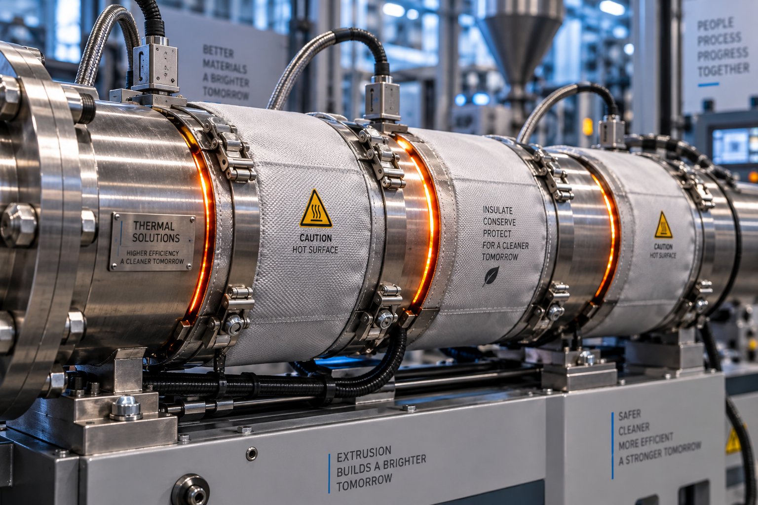
Barrel heating represents 20-30% of a line's energy consumption, making heater selection a surprisingly impactful decision. Three main technologies serve the PVC process and polyolefin extrusion alike, but their efficiency varies dramatically:
- Mica band heaters: The traditional, lowest-cost option. Surface temperatures often run 100 degrees C above the barrel set point, radiating significant heat into the factory environment rather than into the polymer.
- Cast-aluminum heaters: Better thermal contact with the barrel surface improves heat transfer, but external heat loss remains substantial without insulation.
- Ceramic insulated and nano-insulation heaters: Advanced insulation directs virtually all thermal energy inward into the barrel. These designs can reduce heating energy consumption by 30-40% compared to traditional band heaters, reach set temperatures faster, and maintain them with less cycling.
Adding external insulation jackets over any heater type further cuts radiated losses and stabilizes barrel zone temperatures - a low-cost retrofit that pays for itself within months.
On the cooling side, barrel and pipe cooling systems also present optimization opportunities. Closed-loop chiller circuits with variable-speed pumps adjust cooling water flow based on actual thermal demand rather than running at full capacity continuously. Heat recovery exchangers can capture the 60-80 degrees C cooling water and repurpose that energy for resin pre-drying, facility heating, or wash water - recovering up to 50% of the thermal energy that would otherwise be dumped. This interaction between barrel design, screw geometry, and thermal management is worth understanding: the screw's mechanical shear generates heat inside the melt, while barrel heaters add conductive heat from outside. A well-designed screw that delivers the right balance of shear heating reduces the barrel heater's workload, lowering both energy consumption and the risk of localized overheating that degrades melt quality.
Emerging Trends in Sustainable Production
Energy efficiency extends beyond motors and heaters. Several emerging technologies are reshaping how plastic pipes are produced - and how efficiently resources are consumed in the process.
Processing recycled content is gaining traction across the industry. Both post-industrial regrind and post-consumer recyclate (PCR) can be blended into pipe formulations, but they introduce variability in melt flow index, contamination levels, and additive content. Lines designed to handle recycled feedstock need robust melt filtration, tighter temperature control, and gravimetric feeding systems that compensate for bulk density fluctuations. Multi-layer pipe co-extrusion - where a recycled core is sandwiched between virgin inner and outer layers - offers a practical compromise between sustainability goals and performance standards.
Oriented PVC (PVC-O) technology represents a fundamentally different approach to material efficiency. Rather than simply extruding thicker walls for higher pressure ratings, PVC-O uses molecular orientation - stretching the pipe biaxially after extrusion - to align polymer chains and dramatically increase tensile strength and impact resistance. The result is a pipe that meets the same pressure class with significantly less raw material. PVC-O production has evolved from early batch processes in the 1970s to modern inline systems that integrate the orientation step directly into the extrusion line, improving both throughput and consistency.
AI-based inline quality inspection is the newest efficiency multiplier. Smart control systems monitor power draw, melt pressure, dimensional measurements, and surface quality in real time. Machine learning algorithms detect drift before it produces scrap, automatically adjusting screw speed, feed rate, or cooling parameters to maintain optimal operating conditions. These systems also predict maintenance needs - identifying worn screws or degraded heater bands that silently increase energy consumption long before a visible quality problem appears.
For manufacturers looking to reduce operating costs immediately, the following strategies deliver measurable results without requiring a full line replacement:
- Upgrade to IE4/IE5 permanent magnet synchronous motors with vector-control VFDs
- Install ceramic or nano-insulation heater bands on all barrel zones
- Add insulation jackets over existing heater bands as a low-cost first step
- Implement closed-loop cooling water systems with variable-speed pumps
- Install heat recovery exchangers on cooling circuits to recapture thermal energy
- Switch to loss-in-weight feeders for more consistent material dosing and reduced waste
- Request SEC (kWh/kg) data from suppliers and track it as a key performance indicator
- Deploy inline monitoring systems that detect process drift and reduce scrap rates
- Evaluate multi-layer co-extrusion for incorporating recycled content without compromising pipe performance
Each of these measures targets a specific source of waste - whether electrical, thermal, or material. Combined, they can reduce a line's total operating cost by 20-30% compared to a conventionally equipped system running the same product.
Optimizing how energy flows through the production process is one dimension of total system efficiency. Equally important is what happens after the pipe exits the cutter - where downstream equipment, plant layout decisions, and end-of-line automation determine whether those hard-won efficiencies survive all the way to the shipping dock.
Downstream Equipment and Plant Layout Essentials
The extruder melts the polymer. The die shapes the pipe. The cutter sizes it. And then what? For most guides, the story ends right there - as if finished pipes magically transport themselves to a warehouse, perfectly marked, bundled, and ready for delivery. In reality, the equipment and infrastructure decisions between the cutter and the shipping dock determine whether a plastic pipe machine delivers profitable, standards-compliant product or generates piles of unmarked, damaged, improperly handled inventory.
Production engineers know this instinctively. A line that extrudes beautifully but lacks proper socketing, marking, or end-of-line handling is only half a system. Here is everything that happens downstream - and the plant-level infrastructure that makes it all possible.
Socketing, Printing, and Coiling Systems
Many pipe applications - particularly PVC-U drainage and water supply - require a formed socket (or bell) at one end for push-fit or gasket connections. Belling machines heat the pipe end using infrared or contact heaters, then expand it over a mandrel to create the socket shape. Two configurations dominate the market:
- Inline belling machines operate as part of the continuous production flow. Cut pipes are transferred directly from the saw to the belling station without manual intervention. This approach maximizes throughput and eliminates the intermediate handling step, but it requires careful synchronization with line speed and cut length to avoid bottlenecks.
- Offline belling machines process pipes in batches, independent of the extrusion line. They offer more flexibility - allowing different socket configurations without slowing or stopping extrusion - and suit operations running multiple pipe sizes from a single line.
Both types come in fully automatic and semi-automatic variants. Automatic systems handle pipe loading, heating, forming, cooling, and unloading without operator intervention, while semi-automatic versions require manual loading or positioning. For high-volume PVC pipe machine operations producing thousands of meters per shift, fully automatic inline belling is the clear productivity winner.
Pipe printing and marking systems sit further downstream - and they are far more important than many manufacturers realize. Every meter of pipe leaving a production facility must carry permanent identification: manufacturer name, material grade, diameter, wall thickness, pressure rating, applicable standard, production date, and traceability codes. These markings are not optional decorations. They are mandatory for compliance with ISO, ASTM, EN, and DIN standards, and they are the first thing an inspector or end user checks.
Two primary marking technologies serve pipe extrusion lines. Continuous inkjet (CIJ) printers use fast-drying inks formulated for substrates like PVC and PE, available in multiple colors for high-contrast legibility on any pipe color. They handle meter marks, brand logos, quality marks, and variable data - all at full line speed. CO2 laser marking offers an alternative that produces permanent, indelible codes by etching directly into the pipe surface, eliminating ink consumption entirely. Laser systems integrate well into high-speed lines and tight factory layouts using flexible mounting positions.
A critical consideration for any printing system on an extrusion line: the printer must maintain code quality at varying line speeds without stopping or slowing production. Because extrusion lines run continuously - often 24/7 - any printer interruption risks creating stretched, unreadable codes that force product rejection.
For flexible pipe diameters - typically under 63 mm for HDPE, PEX, and PE-RT - coiling machines wind finished pipe into compact coils rather than cutting to fixed lengths. Automatic coilers measure preset lengths, cut, and begin a new coil without stopping the line. Coil sizes typically range from 50 to 500 meters depending on pipe diameter and customer specifications.
Automated Stacking, Bundling, and Packaging
Imagine running a plastic pipe making machine at 400 kg/hr - producing hundreds of cut pipes every shift - and relying on manual labor to stack and bundle them. The math does not work. Operators cannot keep pace with modern line speeds, and manual handling introduces surface scratches, ovality from improper stacking, and inconsistent bundle sizes that complicate loading and transport.
Automatic pipe stackers receive cut pipes from the saw table and arrange them into organized layers. Sensors detect pipe diameter and adjust stacking patterns automatically - hexagonal bundles for round pipes, rectangular arrangements for shipment efficiency. Bundling systems then strap or wrap the stacked pipes for transport, applying programmed strap positions calculated for load stability.
Robotic systems represent the newest evolution in end-of-line handling. Unlike traditional fork-based systems that lift and drop pipes forcefully, anthropomorphic pick-and-place robots handle each pipe deliberately and gently, creating bundles with precision that preserves surface quality. These modular robotic systems can reach production capacities up to 40 tubes per minute in a fully automatic cycle, with an overall 15% performance improvement and 50% changeover time reduction compared to conventional fork-based designs. Their modular construction also means they take up roughly 25% less floor space - a real advantage in crowded production facilities.
The payoff from end-of-line automation extends beyond speed. Reduced product damage lowers scrap rates. Consistent bundle geometry simplifies warehouse stacking and truck loading. And removing repetitive manual lifting tasks from the production floor improves both worker safety and retention.
Plant Layout and Infrastructure Requirements
Here is the practical reality that equipment catalogs never mention: a plastic pipe machine is useless if the building cannot support it. Every production line requires a carefully planned infrastructure foundation - and discovering a shortfall after equipment arrives creates delays, rework costs, and frustration that dwarf the price of upfront planning.
Floor space is the starting point. A typical small-to-medium-diameter pipe extrusion line - including extruder, die, calibration and cooling tanks, haul-off, cutter, and stacking - occupies a linear footprint of 30 to 50 meters. Large-diameter lines with extended cooling sections can stretch beyond 60 meters. Width requirements add another 3 to 5 meters per line, plus aisle space for maintenance access, forklift traffic, and raw material delivery. Multiply by the number of parallel lines you plan to install, and the total floor area adds up fast.
Beyond raw square footage, utility planning must happen alongside equipment placement - not after. As industrial plant design experts emphasize, a layout that ignores utility loads and routes can create voltage drop, pressure loss, congested ceilings, and expensive field changes. Moving a major machine after installation may change feeder lengths, pipe sizes, drainage elevations, and the location of service platforms.
Before signing a purchase order for any line, verify every item on this infrastructure checklist:
- Electrical power supply: Confirm that the facility's transformer and distribution panel can handle the total connected load - including extruder motor, heaters, pumps, and auxiliaries. A medium-diameter line may draw 200-400 kW; large-diameter lines can exceed 600 kW. Account for starting current surges, not just steady-state demand.
- Water supply and drainage: Cooling tanks, vacuum pumps, and calibration systems require continuous water flow at specified pressure and temperature. Closed-loop recirculation systems reduce consumption but still need makeup water and heat rejection capacity. Drainage must handle continuous discharge from cooling circuits - and gravity drainage depends on floor elevation and slope, making it one of the least flexible utilities to relocate later.
- Compressed air: Pneumatic actuators on cutters, stackers, socketing machines, and material handling systems all require clean, dry compressed air at 6-8 bar. Verify that the existing compressor can handle the added demand without starving other factory systems.
- Raw material storage and conveying: Resin silos, pneumatic conveying lines, and drying/mixing stations must be positioned for efficient, contamination-free material delivery to the extruder hopper. Long conveying distances increase energy use and the risk of material degradation or segregation.
- Overhead clearance: Extruder hoppers, feeding systems, and material conveying equipment may extend 4 to 6 meters above floor level. Coordinate with ceiling height, structural framing, lighting, sprinklers, cable trays, and overhead cranes.
- Floor loading capacity: Extruders and gearboxes concentrate significant weight on a small footprint. Confirm that the concrete slab can handle point loads without additional foundation work.
- Finished goods handling: Plan the path from stacker to warehouse to shipping dock. Forklift access lanes, storage zone capacity, and dock door sizing all affect how smoothly product flows out of the facility.
- Future expansion space: Reserve not just floor area but also utility capacity - electrical panel slots, water mains, compressed air loops, and drainage tie-in points - for additional lines. A reserved expansion zone without utility access has limited practical value.
Skipping any of these items creates problems that surface at the worst possible time - during installation or commissioning, when delays carry the highest cost. A plant layout review conducted before equipment is ordered pays for itself many times over.
Getting the physical infrastructure right keeps the line running. Keeping it running well over the long term, however, depends on something else entirely - recognizing the early signs of common production problems and knowing exactly where to look for root causes before defects reach your customers.
Troubleshooting Common Pipe Production Line Problems
A perfectly configured line running perfectly tuned parameters still develops problems. Polymers shift between batches. Wear accumulates silently inside barrels and screw flights. Ambient temperatures change with the seasons. The difference between a production team that loses hours chasing symptoms and one that resolves issues in minutes comes down to a single skill: knowing which defect points to which root cause - and which corrective action to try first.
This section maps the most common failures in PVC pipe extrusion and polyolefin pipe production to their likely origins, giving you a structured diagnostic path rather than a guessing game.
Surface Defects and Their Root Causes
Surface quality is the first thing an inspector notices - and the first thing a customer complains about. Four surface defects account for the vast majority of rejection events on pipe extrusion lines:
- Melt fracture: Severe surface distortion that makes the pipe look twisted or heavily ridged. This happens when shear stress at the die lips exceeds the polymer's critical threshold, forcing the melt into chaotic, oscillating flow. You will see it most often when line speed is pushed too high or die temperature runs too low, increasing melt viscosity beyond what the die geometry can handle smoothly.
- Shark skin effect: A subtler cousin of melt fracture. The pipe surface develops a fine, rough texture - almost like sandpaper - caused by stick-slip flow behavior at the die exit. The melt alternates between adhering to the die wall and releasing, creating micro-scale surface fractures. Reducing extrusion speed, raising die temperature to lower melt viscosity, or polishing the die surface can resolve it.
- Die drool: A sticky buildup of degraded material at the die exit that periodically breaks free and smears across the pipe surface. Low-quality stabilizers, incompatible additives, excess melt pressure, or rough die surfaces all contribute. Left unaddressed, die drool forces frequent production stops for manual cleaning - a direct hit to throughput.
- Rough inner surfaces: When the inside wall of the pipe feels textured or shows visible irregularities, the mandrel temperature or surface finish is usually the culprit. Contamination inside the die, insufficient melt temperature near the mandrel, or degraded material accumulating in flow dead zones can all create internal roughness that compromises hydraulic performance.
Each of these defects originates upstream of where it becomes visible. The pipe surface you see exiting the die was shaped by melt conditions inside the barrel seconds earlier. That is why chasing surface problems at the die alone rarely works - the investigation often needs to trace back to the extruder.
Dimensional and Structural Failures
When you are asked how is PVC pipe manufactured to specification, the answer depends entirely on dimensional control. A pipe that looks perfect on the surface but fails a wall thickness or ovality check is still scrap. Three dimensional failures dominate rejection reports:
Uneven wall thickness is the most common dimensional defect and one of the most damaging - it directly compromises pressure ratings and structural integrity. The causes are deceptively varied. Die centering issues create a consistent thick-thin pattern around the circumference. Uneven cooling in the calibration stage solidifies one side faster than the other, allowing the still-soft side to thin under gravity. Melt temperature variation across the die head produces localized flow imbalances. And as modern production line designs demonstrate, inline laser or ultrasonic wall thickness measurement systems that provide real-time feedback are becoming essential for catching deviations before they propagate through hundreds of meters of product.
Ovality - the pipe cross-section becoming elliptical rather than perfectly round - typically traces to the cooling and calibration stage. Insufficient vacuum pressure in the calibration tank allows the pipe to sag under its own weight before it fully solidifies. Uneven water temperature inside the tank creates asymmetric cooling that distorts roundness. Excessive or uneven haul-off tension can also pull the pipe out of shape between the calibration sleeve and the puller. Well-designed vacuum calibration systems use multiple sleeves with stable, independently controlled vacuum pressure and closed-loop cooling water temperature management to maintain roundness.
Vacuum calibration failures encompass a broader category: situations where the calibration system cannot maintain target dimensions. Worn or damaged calibration sleeves - especially bronze sleeves that develop scoring from abrasive fillers in PVC compounds - lose their ability to size the pipe accurately. Water scale buildup inside the vacuum tank restricts flow and disrupts cooling uniformity. And if vacuum pump capacity degrades over time due to wear or clogged filters, the negative pressure drops below the threshold needed to hold the pipe against the sleeve.
Process Instability and Output Variation
Surging - the rhythmic oscillation of extruder output - is one of the most frustrating problems to diagnose because its effects show up everywhere: wall thickness variation, pressure swings, inconsistent surface finish, and fluctuating line speed. As Plastics Technology details in extensive case studies, the most common root cause in smooth-bore single-screw extruders is improper temperature in the solids conveying section. A feed casing that runs too hot, or inadequate screw cooling, disrupts the balance between forwarding forces at the barrel wall and retarding forces at the screw root. The result is erratic solids feeding that sends pressure waves down the entire barrel. Worn screw flights compound the problem by reducing conveying efficiency and allowing backflow that amplifies output variation.
Color streaking signals poor pigment or masterbatch dispersion. Agglomerated pigment particles, low-quality masterbatch, or dead spots inside the barrel where old material accumulates and periodically flushes into the melt stream all produce visible streaks. Increasing back pressure improves dispersion, but the more effective long-term fix is regular barrel and die cleaning combined with screws designed with better mixing elements.
Thermal degradation shows up as discoloration, brittleness, smoke, or an acrid odor. It is particularly dangerous in how PVC pipes are manufactured, since PVC releases hydrochloric acid when overheated - a corrosive gas that damages equipment and compromises pipe integrity. Degradation points to excessive barrel temperatures, too much shear heat from high screw speeds, or blocked cooling channels that prevent heat dissipation. Dead zones inside the barrel - areas where material stagnates and cooks - are a hidden cause that becomes more severe as barrel and screw wear increases the volume of stagnant pockets.
Many surface and dimensional defects trace back to the same root cause: worn screws and barrels. As screw flights erode and barrel bores widen, mixing efficiency drops, backflow increases, melt temperature becomes inconsistent, and output stability degrades - producing defects that appear unrelated until you inspect the wear parts.
The troubleshooting matrix below consolidates the most common problems, their likely causes, and the corrective actions that address each one. Print it, laminate it, and keep it at the operator station - it will save hours of diagnostic time.
| Problem | Likely Cause(s) | Corrective Action(s) |
|---|---|---|
| Melt fracture (severe surface distortion) | Excessive shear stress at die exit; melt velocity too high; die temperature too low | Reduce screw RPM; increase die temperature; use resin with higher melt flow index |
| Shark skin (rough, micro-cracked surface) | Stick-slip flow at die lips; high shear rate at die exit | Lower extrusion speed; raise die temperature; polish die land surfaces |
| Die drool (material buildup at die exit) | Incompatible additives; excess melt pressure; rough die surfaces; degraded lubricant system | Polish die exit surfaces; reduce melt pressure; adjust lubricant ratio; improve flow channel geometry |
| Rough inner surface | Low mandrel temperature; contamination in die; degraded material in flow dead zones | Increase mandrel temperature; clean die thoroughly; purge barrel to remove degraded residue |
| Uneven wall thickness | Die centering misalignment; uneven cooling; melt temperature variation; worn screw/barrel | Re-center die; balance cooling water flow; check barrel zone temperatures; inspect screw and barrel for wear |
| Ovality (elliptical cross-section) | Insufficient vacuum calibration pressure; uneven cooling water temperature; excessive haul-off tension | Increase and stabilize vacuum pressure; equalize cooling water temperature; reduce and balance haul-off tension |
| Surging (output oscillation) | Hot feed casing or screw; worn screw flights; inconsistent feeding; inadequate screw cooling | Check feed casing temperature (should be warm, not hot); verify screw cooling water flow; replace worn screw; use gravimetric feeder |
| Color streaking | Poor pigment dispersion; agglomerated masterbatch; dead spots in barrel or die | Increase back pressure; use higher-quality masterbatch; clean barrel and die; upgrade to mixing screw elements |
| Thermal degradation (discoloration, brittleness, odor) | Excessive barrel/die temperature; high shear from screw speed; blocked cooling channels; barrel dead zones | Reduce temperature in overheating zones; lower screw speed; clean cooling channels; inspect barrel for stagnation areas caused by wear |
| Bubbles and voids | Moisture in raw material; trapped air during feeding; excessive die temperature; volatile additives | Dry materials thoroughly; install vacuum venting; reduce melt temperature; review additive formulation |
Notice how many corrective actions in that matrix circle back to screw and barrel condition. A production team that monitors wear parts proactively - tracking torque trends, pressure consistency, and output stability over time - catches degradation before it cascades into the multi-symptom chaos that makes troubleshooting feel impossible. That proactive mindset naturally extends beyond diagnosis into the broader discipline of maintenance planning, wear part replacement, and sourcing decisions that determine how long a line maintains peak performance.
Maintenance, Wear Parts, and Maximizing Line Lifespan
Purchasing a plastic pipe production line is a capital investment measured in hundreds of thousands - sometimes millions - of dollars. Protecting that investment over the next fifteen to twenty years depends less on the equipment's original build quality and more on what happens after commissioning. A disciplined maintenance program extends component life, preserves output quality, and prevents the kind of slow, invisible degradation that quietly erodes profitability long before anything actually breaks.
Yet maintenance is the topic that virtually every buyer's guide ignores. Suppliers talk about what their lines can do when new. Nobody talks about what keeps them performing at that level five, ten, or fifteen years later. This section fills that gap with a structured maintenance framework, a clear explanation of which parts wear out and when to replace them, and practical guidance on sourcing components that restore - or even exceed - original performance.
Routine Maintenance Schedules and Best Practices
Effective maintenance is not about fixing things when they fail. It is about catching drift early - when the correction is still a scheduled task rather than an emergency shutdown. The rhythm matters as much as the individual checks. A structured daily, weekly, monthly, and annual schedule ensures nothing falls through the cracks, even when production pressure tempts operators to skip "just this one inspection."
The table below organizes the most critical maintenance tasks by frequency. Adapt it to your specific line configuration and polymer type, but treat these intervals as a starting point - not a wish list.
| Frequency | Area | Task | Why It Matters |
|---|---|---|---|
| Daily | Extruder | Listen for abnormal motor or gearbox noise; verify zone temperatures match setpoints; record melt pressure at a fixed screw speed | Catches bearing wear, heater failure, or screen loading before they cause unplanned stops |
| Daily | Die head | Inspect die lips for material buildup or leakage at adapter joints | Prevents streaks, black specks, and wall thickness variation from degraded resin accumulation |
| Daily | Cooling system | Check water level, inlet temperature, spray coverage, and vacuum gauge readings | Cooling drift causes dimensional defects often misdiagnosed as die or material problems |
| Daily | Haul-off and cutter | Confirm belt contact and clamping force; check blade condition and cut timing accuracy | Slip creates surface marks; dull blades produce burrs and angled cuts |
| Daily | Controls | Review active alarms; verify cabinet fan operation and emergency stop function | Repeated ignored warnings escalate into VFD trips and unsafe operating conditions |
| Weekly | Gearbox | Check oil level and color; inspect belt tension or coupling condition | Dark or foaming oil signals lubrication breakdown that leads to heat buildup and output loss |
| Weekly | Barrel heaters | Inspect heater band terminals for discoloration or corrosion | Loose terminals create electrical resistance, increasing current draw and accelerating heater failure |
| Weekly | Water circuit | Clean strainers, filters, and spray nozzles; inspect vacuum tank seals | Partially blocked filters reduce cooling capacity long before the pump fails |
| Weekly | Cutter | Sharpen or replace blades; check clamp alignment | Dull blades increase cutting force, stressing the mechanism and producing inconsistent lengths |
| Weekly | Electrical cabinet | Clean VFD heat sinks; tighten sample terminal blocks; verify grounding | Dust and vibration cause intermittent faults that are nearly impossible to diagnose during production |
| Monthly | Screw and barrel | Measure clearance at feed, transition, and metering sections; compare to baseline | Trend data reveals wear progression and enables planned replacement before quality collapses |
| Monthly | Gearbox | Record oil temperature under stable load; compare to previous readings | Rising temperature at the same load points to lubrication degradation or internal wear |
| Monthly | Vacuum pump | Compare ultimate vacuum against commissioning baseline | Capacity loss indicates oil, vane, or seal issues that gradually degrade calibration stability |
| Monthly | Calibration sleeves | Measure bore diameter for wear; inspect for scoring or buildup | Worn sleeves lose dimensional accuracy, producing pipes outside tolerance |
| Monthly | Controls | Back up PLC, HMI, and VFD parameters; verify motor insulation resistance | A current backup prevents days of reprogramming after a controller replacement |
| Annually | Full line | Complete screw and barrel dimensional audit; gearbox oil flush and refill; motor insulation test; cooling system descale and water quality analysis; die and adapter disassembly, inspection, and repolishing; comprehensive electrical inspection | Establishes updated baselines for all wear-trend data and addresses accumulated degradation that shorter-interval checks cannot resolve |
A practical insight from experienced production teams: daily checks should take no more than 10 to 15 minutes per shift. Keep the checklist short enough that operators actually complete it every time. Recording only abnormal items - rather than documenting every normal reading - reduces paperwork fatigue and focuses attention on deviations. As extrusion maintenance specialists emphasize, one reading tells you the current state, but repeated readings over time reveal the direction of wear. Trend data is the difference between planned maintenance and emergency repair.
Seasonal conditions also affect what deserves extra attention. Hot weather reduces cooling tower efficiency and heats electrical cabinets. High humidity creates condensation inside control panels and promotes biological growth in water circuits. Dusty environments clog cabinet filters and contaminate lubricants. Adjusting your inspection intervals to account for these environmental factors prevents failures that a standard, unchanging schedule would miss.
Wear Parts Replacement and Line Longevity
Every production line contains components designed to be consumed - parts whose gradual degradation is expected, budgeted for, and managed through timely replacement. Treating these as permanent fixtures is a recipe for slowly declining output that nobody notices until profitability has already eroded.
The primary consumable wear parts in a pipe extrusion line include:
- Screw flights: The hard-faced tips of the screw flights gradually erode from abrasive contact with the polymer, fillers, and barrel wall. As flight clearance increases, backflow over the flights rises, reducing conveying efficiency and mixing quality.
- Barrel bore: The barrel's inner surface - whether nitrided steel or bimetallic liner - wears in tandem with the screw. Barrel wear is typically slower than screw wear. An iron-based bimetallic barrel liner typically lasts about three times the service life of a screw, but both must be monitored together because their combined clearance determines system performance.
- Calibration sleeves: Bronze or stainless steel sizing sleeves develop scoring and bore enlargement from continuous contact with the hot, abrasive-laden pipe surface. Worn sleeves produce pipes with oversized or inconsistent outer diameters.
- Cutter blades: Saw blades and chipless cutter inserts dull with every cycle, eventually producing burrs, angled cuts, and increased cutting force that stresses the entire cutting mechanism.
- Haul-off pads and belts: Rubber pads and belt surfaces compress and wear from continuous grip on the pipe. Worn pads lose traction, causing slippage that directly affects wall thickness and cut-length accuracy.
- Die components: Die lips, mandrels, and flow channel surfaces erode from abrasive fillers and corrosive decomposition products - especially in rigid PVC processing where hydrochloric acid release attacks metal surfaces.
Of all these wear parts, the screw and barrel pairing deserves the closest monitoring because their degradation affects everything downstream. When screw flights wear and flight clearance widens, the consequences cascade through the entire process. The extruder's specific rate drops - meaning you need higher screw speeds to maintain the same output. Higher screw speeds generate more shear heat, raising discharge temperatures. As extrusion research has documented, a 100-mm extruder running HDPE at 150 kg/hr showed discharge temperatures climbing from 236 degrees C with new clearances to nearly 246 degrees C as wear progressed - a 10-degree increase that can push the process beyond the material's thermal stability window.
Eventually, the operator can no longer compensate. The line must be derated - running at reduced throughput to keep discharge temperature within acceptable limits. A 13% rate reduction on a line that runs 24/7 translates directly into lost revenue and missed delivery commitments.
So when should you replace rather than continue compensating? Three common guidelines circulate in the industry:
- When flight clearance reaches four times the original new clearance (the "4x rule")
- When the hard facing on flight tips is completely worn through
- When the economics of reduced throughput and increased scrap exceed the cost of new components
The third criterion is the most rational. Critical applications - how PVC pipe is made for pressure-rated water supply, for example - cannot tolerate the dimensional and structural variability that worn components produce. These lines may need screw replacement at 2x the original clearance. Less demanding applications like non-pressure drainage pipe can tolerate more wear before replacement becomes necessary. The decision should always be driven by economics and quality requirements, not by an arbitrary mileage counter.
One additional caution: a screw should never be refurbished more than three times. Each reapplication of hard facing through welding deteriorates the base metal, increasing the risk of delamination where the new hard facing separates from the screw body during operation - a failure mode that can damage the barrel and contaminate the melt stream with metal particles.
Keeping a spare screw in storage is a simple but high-impact practice. When the active screw reaches the end of its service life, the spare can be installed during a planned changeover - typically within a day - rather than shutting the line down for weeks while a replacement is manufactured and delivered. The worn screw then goes for refurbishment or replacement at a pace dictated by convenience, not crisis.
Sourcing Quality Replacement Components
Replacement is only as good as the part you replace with. A bargain-priced barrel that does not match the original metallurgy, bore finish, or heating zone configuration will underperform from day one - and may actually accelerate wear on the new screw paired with it.
Three metallurgical strategies define the replacement barrel market, each suited to different processing demands:
- Nitrided steel barrels: The baseline option. A nitrogen-hardened surface layer provides moderate wear resistance suited to unfilled polyolefins and non-abrasive formulations. Lower cost, but shorter service life when processing filled or abrasive compounds.
- Bimetallic barrels: A centrifugally cast wear-resistant alloy liner bonded inside a structural steel outer shell. The liner's high tungsten carbide content delivers substantially longer life when processing glass-filled, mineral-filled, or calcium carbonate-loaded formulations. As industry experts note, the compatibility between barrel lining material and screw flight hard facing is critical - mismatched alloys can cause galling, where metal surfaces weld together under pressure and then fracture, accelerating wear on both components.
- Specialty alloy barrels: Nickel-based or cobalt-based alloys engineered for corrosive environments - essential for PVC pipe manufacturing machine applications where hydrochloric acid release attacks standard iron-matrix liners.
When sourcing replacements, the goal is precision matching. The replacement barrel's bore diameter, straightness, concentricity, and surface finish must meet or exceed the original specifications. Bore tolerances for plasticating extruders are typically the nominal diameter with just 0.001 inch oversize tolerance - a level of precision that rules out generic, off-the-shelf components for most pipe extrusion applications.
This is where working with a specialist supplier makes a measurable difference. NANHAIYA, for example, specializes in custom and replacement single screw barrels for pipe, film, sheet, pelletizing, recycling, and general-purpose extrusion lines. Their approach centers on engineering barrels to match specific processing requirements - polymer type, filler content, temperature profile, and the wear patterns observed on the component being replaced. Custom barrel configurations can address recurring issues like localized hot spots, accelerated wear in the feed zone from grooved-feed designs, or bore enlargement patterns unique to a specific material formulation. For production teams dealing with performance degradation on HDPE, PP, or flexible PVC pipe lines, a precision-matched replacement barrel restores the tight flight clearances and thermal consistency that keep output quality and throughput at their original levels.
Beyond barrel sourcing, a few broader replacement practices protect your investment:
- Always measure the barrel bore before ordering a new screw. Installing a new screw into a worn barrel wastes the screw's precision - the oversized barrel negates the tight clearances the new screw was machined to deliver.
- Document the original screw geometry. Channel depths, compression ratio, flight pitch, and mixing element design should all be recorded during commissioning. Without this documentation, replacement screws risk being manufactured to generic specifications that may not match your process.
- Verify alignment after any barrel or screw change. Barrel misalignment - caused by shifted supports, thermal warping, or foundation settling - is a leading cause of premature wear that many teams overlook. Even a fraction of a degree of misalignment concentrates wear on one side of the barrel, creating an asymmetric wear pattern that accelerates with every operating hour.
- Track wear data over multiple replacement cycles. If each successive screw wears faster than the last, the root cause is likely upstream - barrel wear, alignment, resin contamination, or an incompatible alloy pairing - rather than a screw quality issue.
A plastic pipe production line is a long-term asset. The manufacturers who extract the most value from theirs are not the ones who bought the most expensive equipment - they are the ones who built maintenance discipline into their daily operations, replaced wear parts before performance collapsed, and sourced components with the metallurgical precision their process demands. That combination of vigilance, planning, and quality sourcing is what turns a depreciating machine into a revenue-generating asset for decades.
Frequently Asked Questions About Plastic Pipe Production Lines
1. What machines are included in a plastic pipe production line?
A complete plastic pipe production line includes a raw material feeding and dosing system, an extruder (single-screw or twin-screw depending on the polymer), an annular die head, a vacuum calibration tank, spray or immersion cooling tanks, a caterpillar or belt haul-off unit, a cutting system (planetary saw or chipless cutter), and finishing equipment such as socketing machines, printers, and automatic stackers. Each machine's throughput must be balanced with the others, since the slowest component determines the entire line's maximum output rate. Barrel quality also plays a critical role - suppliers like NANHAIYA (nhyscrews.com) offer custom single screw barrels engineered to match specific polymer and line requirements, directly influencing melt consistency and throughput.
2. What is the difference between a PVC pipe production line and an HDPE pipe production line?
The primary difference lies in the extruder architecture and processing parameters. PVC pipe lines typically use conical twin-screw extruders because PVC is heat-sensitive and requires low-shear, controlled mixing to avoid thermal degradation. Processing temperatures range from 160-200 degrees C. HDPE lines use single-screw extruders with grooved-feed barrel designs that improve solids conveying efficiency, running at higher temperatures of 190-230 degrees C. HDPE also demands longer cooling sections due to its higher specific heat capacity and crystallization behavior. Additive strategies differ as well - PVC requires thermal stabilizers and lubricant systems, while HDPE uses UV stabilizers, carbon black, and antioxidants.
3. How do you calculate the actual output of a pipe extrusion line?
A line's real output equals the capacity of its slowest component - not the extruder's headline rating. To perform a basic line-balancing check, first identify the extruder's maximum output in kg/hr for your specific polymer. Then calculate the cooling section's heat-removal capacity for the target pipe size and material, since different polymers require vastly different cooling energy. Finally, verify the haul-off unit's pulling force and speed range. If the extruder can push 500 kg/hr but the cooling section only handles 350 kg/hr, your actual production rate is 350 kg/hr. Always request the specific energy consumption (SEC) in kWh/kg from suppliers to compare true operating efficiency.
4. What causes uneven wall thickness in extruded plastic pipes?
壁厚不均源于多种潜在原因。模具中心未对准会在管道圆周上形成均匀的厚薄不均现象。校准槽内冷却不均会导致一侧凝固更快,而较软的一侧则在重力作用下变薄。模头各处的熔体温度差异会造成局部流动不平衡。螺杆螺纹磨损和料筒内径增大也会降低混合效率并导致熔体输送不稳定。纠正措施包括重新调整模具中心、平衡冷却水流量和温度、检查料筒区域温度以及检查螺杆和料筒间隙的磨损情况。
5. 管道挤出生产线上的螺杆和料筒应该多久更换一次?
更换时机取决于磨损程度及其对产品质量的影响,而非固定计划。行业普遍建议,当飞行间隙达到初始间隙的四倍时进行更换。然而,最合理的做法是经济效益分析:当产量下降、废品增加和能源消耗上升造成的损失超过新部件的成本时,就应该更换。对于压力等级较高的水管等关键应用,可能只需在初始间隙达到两倍时就需要更换。双金属筒衬的使用寿命通常是螺钉的三倍左右。储备备用螺钉可以实现计划内的更换,只需一天即可完成,而无需像以往那样等待数周的生产和交付。
Written by
Nanhaiya Technical Team
Zhoushan Nanhaiya Plastic Machinery Co., Ltd.
The Nanhaiya technical team supports screw and barrel manufacturing projects through application review, technical communication, custom manufacturing coordination, and production and quality control.
Discuss Your Application
Related Articles
More insights on screw barrel technology and plastics processing.

What Nobody Tells You About Screw Barrel For Plastic Machine Design
Oct 10, 2026
Learn how screw barrel for plastic machine design affects melt quality, throughput, and wear life. Covers geometry, resin matching, troubleshooting, and sourcing.
Read Article
Single Screw Extruder for Sheet: Stop Guessing, Start Specifying
Oct 9, 2026
Learn how to specify a single screw extruder for sheet production. Covers screw geometry, resin-specific processing, troubleshooting, and maintenance best practices.
Read Article
PE Pipe Extruder Machine: What Datasheets Won't Tell You
Oct 9, 2026
Learn how a PE pipe extruder machine works, key specs explained, material grade selection, maintenance tips, and buyer guidance beyond the datasheet.
Read ArticleLooking for something else?
Search by material, symptom or product and jump straight to the relevant page.
These are navigation suggestions based on keyword matching — not a quotation, not a delivery commitment, and not a substitute for engineering review. Final specification is confirmed by our engineers against your drawings and processed material.
Need help with screw barrel selection?
Share your machine model, processed material and application. Our team can help with pricing and technical support.