

What Is a Plastic Pipe Extrusion Machine and Why It Matters
When someone asks "what is extrusion" in the context of plastics manufacturing, the answer almost always leads back to pipe production — one of the highest-volume applications of the entire extrusion process. Yet most buyers focus on output specs and price tags while overlooking the anatomy of the machine itself. That knowledge gap can cost you years of production efficiency.
Defining the Plastic Pipe Extrusion Machine
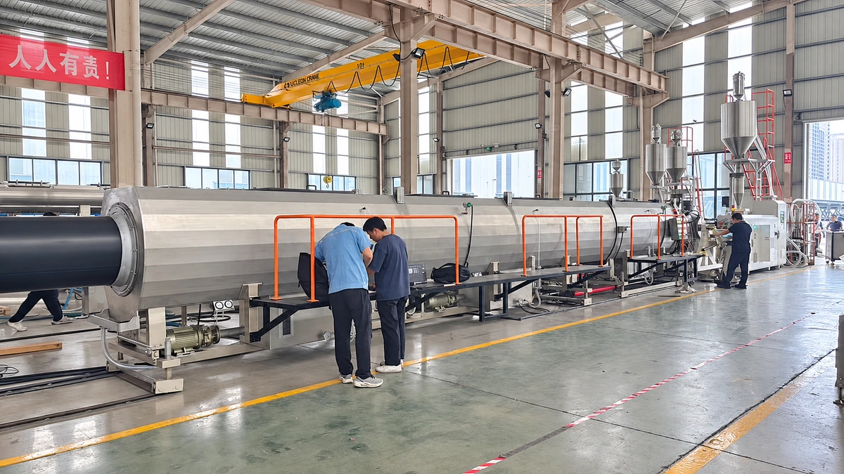
A plastic pipe extrusion machine is an integrated production system that melts, shapes, and solidifies thermoplastic materials into continuous hollow profiles with precise dimensional control. It combines an extruder unit, shaping die, calibration tooling, cooling tanks, haul-off devices, and cutting stations into a single coordinated line. In the simplest definition for extrusion applied to pipe manufacturing, raw plastic enters one end as pellets or powder and exits the other as a finished, ready-to-ship pipe.
Understanding what is an extruder helps clarify how the system works: it is the motorized screw-and-barrel assembly at the heart of the line that generates the heat and pressure needed to convert solid resin into a uniform melt. The meaning of extruder, then, extends beyond a single component — it represents the engine driving every meter of pipe that rolls off the production floor.
Why Pipe Extrusion Matters in Modern Manufacturing
Imagine every new housing development, municipal water network, gas distribution grid, and agricultural irrigation project built in the last decade. Plastic pipes are embedded in virtually all of them. Global demand drivers for pipe extrusion span water supply, stormwater drainage, sewage systems, gas distribution, telecommunications conduit, and industrial chemical transport.
The global plastic pipes market was valued at $26.25 billion in 2024 and is projected to reach $44.9 billion by 2035, growing at a 5.0% CAGR — a trajectory fueled by urbanization, infrastructure renewal, and the shift from metal and concrete to lightweight, corrosion-resistant thermoplastics.
Different end-use demands call for different materials, and each one behaves uniquely inside the pipe extrusion line. PVC dominates construction drainage and potable water systems thanks to its rigidity, low cost, and proven track record. HDPE delivers superior flexibility, fatigue resistance, and leak-free fusion joints for pressurized water mains and gas distribution networks. PP serves high-temperature drainage and chemical-resistant industrial piping, while PE-RT has carved out a growing niche in radiant floor heating and hot-water plumbing. According to Market Research Future, the PE segment alone — primarily HDPE — is expected to grow from $10.5 billion to $17.5 billion by 2035, making it the fastest-expanding material category in the market.
Each of these polymers places distinct demands on screw geometry, barrel temperatures, die design, and cooling strategy. That reality is exactly why understanding the full anatomy of a pipe extrusion line — component by component — separates informed buyers from those who learn expensive lessons on the production floor.
Complete Anatomy of a Pipe Extrusion Line
Knowing what a plastic pipe extrusion machine does is one thing. Understanding the individual stations that make it work — and how they depend on each other — is where real production insight begins. Picture the line as a relay race: every station hands off to the next, and a weak link anywhere ripples through to the finished pipe. Here is a component-by-component walkthrough from raw resin to stacked product.
The Extruder Unit and Feed System
The extruder is the heart of every pipe line, and it starts at the hopper — the funnel-shaped reservoir sitting on top of the machine. Raw material, whether pellets or powder, drops from the hopper through the feed throat into the extruder feed barrel. That barrel houses a rotating screw whose geometry is specifically engineered to convey, compress, and melt the resin as it travels forward.
Driving the screw is a high-torque motor paired with an extruder gearbox that converts motor speed into the slower, higher-torque rotation the screw demands. Think of it like a bicycle's gear system — the gearbox lets the motor operate at efficient RPMs while the screw turns at the precise speed needed for consistent melt quality. Upstream of the barrel, gravimetric or volumetric dosing systems meter additives, colorants, or stabilizers into the material stream with repeatable accuracy. Gravimetric feeders weigh material in real time, making them especially valuable when tight recipe control directly affects pipe performance.
Die Head Assembly and Calibration Tooling
Once the extruder machine delivers a homogeneous melt, the material passes through a screen changer — a filtration device that catches contaminants and unmelted particles before they reach the shaping stage. From there, the melt enters the die head, the annular tooling assembly where an outer die ring and an inner mandrel form the molten polymer into a hollow profile. The relationship between die gap and mandrel position determines the pipe's starting diameter and wall thickness.
Immediately downstream sits the vacuum calibration tank. Here, a precision-machined sizing sleeve contacts the pipe's outer surface while a controlled vacuum pulls the still-soft wall outward against that sleeve, locking in the pipe's final outside diameter. Without accurate calibration, even the best extrusion equipment upstream cannot produce dimensionally compliant pipe.
Cooling and Haul-Off to Cutting Stations
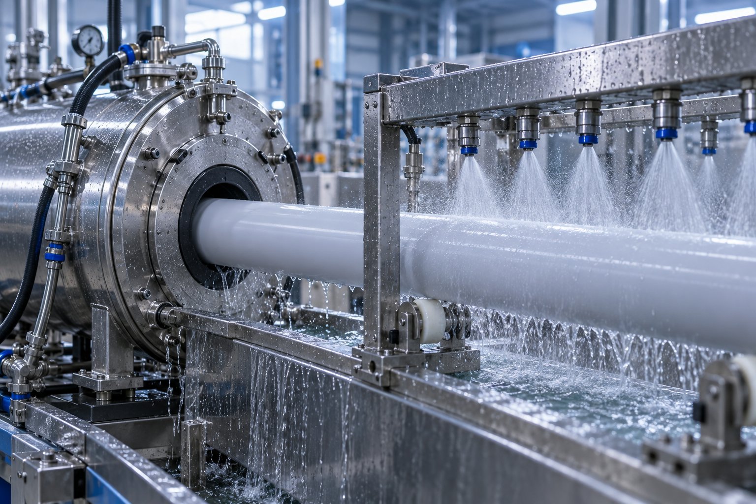
The calibrated pipe is far from cool enough to handle. Spray cooling baths — sometimes stretching several meters — progressively reduce the pipe temperature using staged water jets. Gradual cooling matters because aggressive temperature drops create internal stress, warping, or ovality defects.
A caterpillar-type or belt-type haul-off unit then grips the pipe and pulls it forward at a carefully controlled speed. The haul-off speed relative to extruder output is critical: too fast and walls thin out; too slow and they thicken beyond tolerance. At the end of the line, a planetary saw or chipless cutting system trims pipe to specified lengths, and automated stackers or coilers organize the finished product for packaging.
To give you a clear mental map, here is the full station sequence from upstream to downstream as it appears on a typical production floor:
- Material storage and dosing system (gravimetric or volumetric feeder)
- Hopper and feed throat
- Extruder barrel and screw assembly with drive motor and gearbox
- Screen changer and breaker plate
- Die head with mandrel (annular shaping tooling)
- Vacuum calibration tank with sizing sleeve
- Spray cooling bath (single or multi-stage)
- Caterpillar or belt-type haul-off unit
- Ink-jet printer or embossing station for pipe marking
- Planetary saw, chipless cutter, or guillotine cutting system
- Pipe stacker, tilt table, or automatic coiler
Every station on this list influences the next. The extrusion machinery upstream dictates melt quality, which the die shapes, calibration locks in, cooling stabilizes, and the haul-off preserves. Buyers who evaluate only the extruder while overlooking downstream equipment often discover that their bottleneck was never the screw and barrel — it was something six stations down the line.
Of course, the extruder's screw and barrel are far from generic components. Their geometry varies dramatically depending on whether you are processing PVC powder or HDPE pellets — a distinction that shapes everything from melt temperature to pipe surface finish.
Screw and Barrel Design Principles for Pipe-Grade Materials
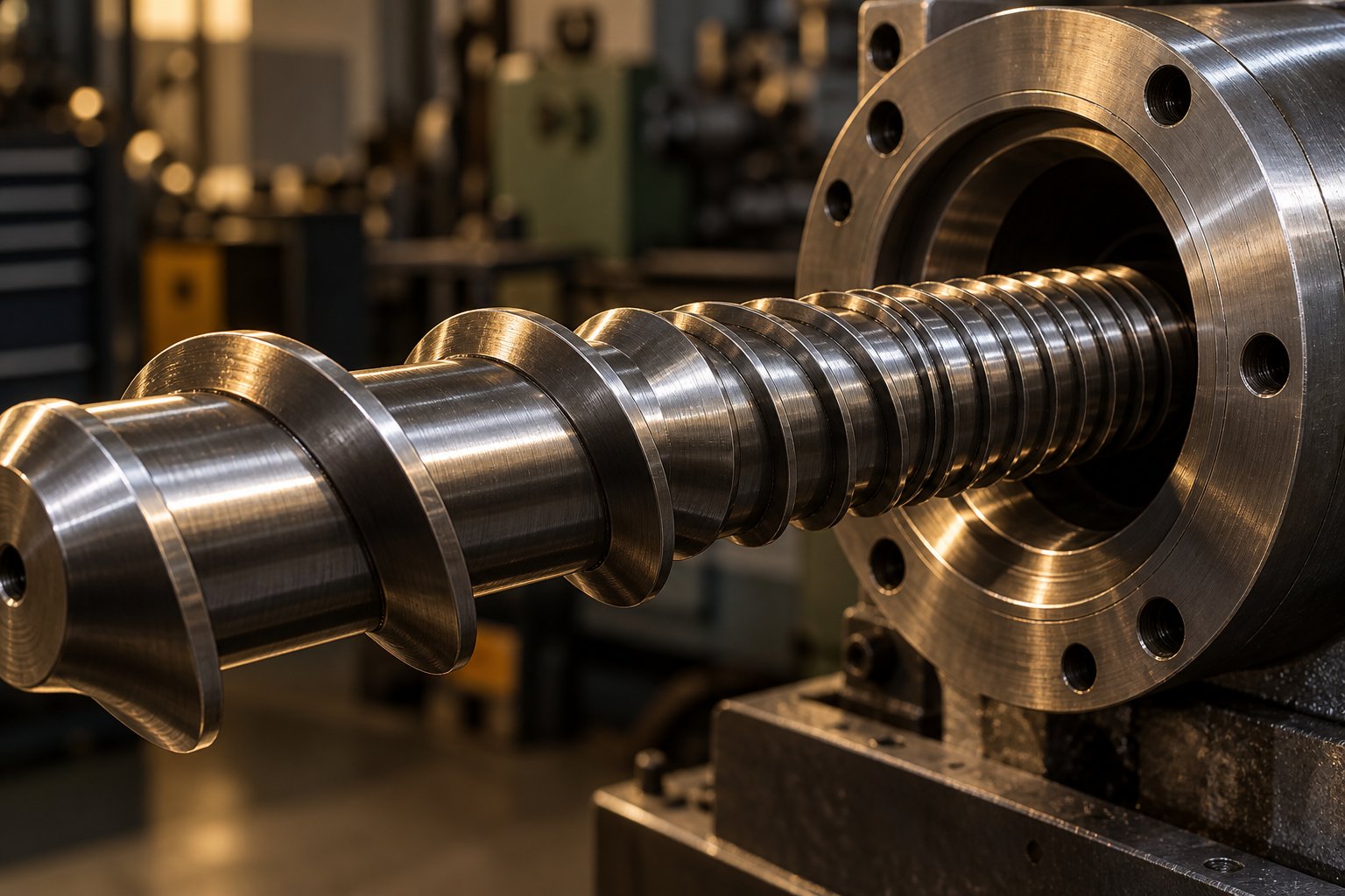
The screw and barrel might look like simple steel cylinders from the outside, but their internal geometry is where melt quality is won or lost. Two pipe extrusion lines can sit side by side with identical downstream equipment and die tooling, yet produce dramatically different results — all because one has a screw extruder matched to its target polymer and the other does not. This is especially true in pipe production, where wall thickness uniformity, surface finish, and long-term pressure rating depend on how evenly and gently the resin is melted.
Here is the critical distinction most buyers miss: a screw designed for HDPE will destroy PVC, and a PVC screw will underperform on polyolefins. The reason comes down to thermal sensitivity. PVC has a very narrow processing window and degrades rapidly under excessive shear or heat, while semi-crystalline polymers like HDPE and PP tolerate — and even require — higher energy input to achieve complete melting. That fundamental difference drives every design decision in the extruder screw and barrel.
How Screw Geometry Affects Melt Quality in Pipe Production
Every single screw extruder screw is divided into three functional zones, each with a specific job in the material extrusion process:
- Feed zone — Deep screw channels accept solid pellets or powder from the hopper and convey them forward. The groove depth here determines how much raw material the screw can intake per revolution.
- Compression (transition) zone — Channel depth gradually decreases, compacting the material against the barrel wall. This generates frictional heat and pressure that begin melting the resin.
- Metering zone — Shallow, uniform channels deliver a homogeneous melt at consistent pressure to the die head. Melt temperature and output stability are largely determined here.
The ratio between feed zone groove volume and metering zone groove volume is called the compression ratio, and it varies significantly by material. Polyethylene (PE) and polypropylene (PP) typically require compression ratios between 3:1 and 4:1 to fully densify and melt their semi-crystalline pellets. Rigid PVC in granule form, by contrast, works best with a compression ratio of just 2:1 to 3:1 — any higher, and excessive shear generates enough heat to trigger thermal degradation.
Then there is the L/D ratio — the screw's working length divided by its diameter. For polymer extrusion in pipe applications, this typically falls between 25:1 and 33:1. A longer screw provides more residence time, better mixing, and higher output potential at increased speeds. However, thermally sensitive materials like PVC actually benefit from shorter L/D ratios because extended residence time raises the risk of heat-induced degradation. HDPE and PP pipe screws, on the other hand, often push toward the 30:1 to 33:1 range to ensure complete melting of their higher-crystallinity structure.
What happens when screw geometry is wrong for the material? You will see the evidence in the finished pipe. Burn marks and yellowing signal localized overheating from excessive shear — a telltale sign of too-high compression ratio or too-long residence time on PVC. Uneven wall thickness points to inconsistent melt pressure caused by improper metering zone design. And surface roughness or visible streaks often trace back to incomplete plasticization from a poorly matched screw. In the extrusion process for pipe production, these are not cosmetic flaws — they compromise pressure ratings, joint integrity, and long-term service life.
Barrel Construction and Wear Considerations
The barrel is the screw's partner, and its condition directly shapes output quality and energy efficiency. Imagine running a high-precision extruder screw inside a barrel with worn bore dimensions — the increasing clearance allows melt to leak backward, reducing throughput and introducing temperature inconsistencies. Industry data shows that the clearance between screw and barrel is generally controlled within 0.1 to 0.6 mm, and even small deviations beyond this range cause measurable drops in extrusion pressure and plasticization quality.
Standard pipe extrusion barrels start with nitrided steel — a hardening treatment that creates a wear-resistant surface layer at a reasonable cost. For more demanding applications, especially lines running filled compounds or recycled material with contaminants, bimetallic barrels offer a significant performance upgrade. These use a structural steel outer body with a centrifugally cast alloy liner — typically 1 to 2 mm thick — containing chromium, nickel, or carbide elements. According to industry analysis from Juyuan Machinery, bimetallic screw barrels deliver 3 to 7 times the abrasion resistance of standard nitrided barrels, depending on alloy grade.
Barrel zone heating and cooling also play a pivotal role. Multiple independently controlled heating zones along the barrel length let operators fine-tune the temperature profile to match the polymer's melting behavior. PVC barrels typically run cooler with tighter temperature bands, while HDPE lines push higher temperatures with more aggressive compression-zone heating. Ceramic band heaters or infrared elements provide the heat, while air or water-cooled barrel jackets pull excess energy out of zones where shear friction generates more heat than the material can tolerate. When barrel wear advances, these temperature zones lose their effectiveness — worn bore surfaces change heat transfer characteristics, and the controller has to work harder to compensate, driving up energy consumption.
This is precisely why replacement and custom-engineered barrels are not optional maintenance items — they are production-critical components. A worn barrel does not just reduce output; it degrades wall thickness consistency, increases scrap rates, and shortens die life by delivering an uneven melt. For operators dealing with barrel wear or planning a screw-barrel upgrade, working with a specialized manufacturer makes a measurable difference. NANHAIYA, for example, offers custom and replacement single screw barrels engineered specifically for pipe extrusion lines, along with configurations tailored to film, sheet, pelletizing, and recycling applications. Their pipe-specific barrel solutions are designed to restore or improve dimensional precision, material compatibility, and thermal performance — the three factors that most directly affect finished pipe quality.
Getting the screw and barrel combination right is foundational, but the melt they produce still has to be shaped into a precise hollow profile. That shaping happens in the die head and mandrel assembly — a component where design choices quietly determine whether your pipe meets spec or misses it by just enough to matter.
Die Head and Mandrel Technology That Defines Pipe Quality
The screw and barrel deliver a uniform melt, but the extrusion die is the component that actually gives your pipe its shape. Think of it this way: the extruder is the engine, while the die head is the steering wheel. A flawless melt stream pushed through a poorly designed die still produces defective pipe. In the extrusion of pipes, three distinct die architectures dominate — and the one you choose directly affects concentricity, surface finish, weld line strength, and ultimately how that extruded pipe performs under pressure for decades.
Spider Dies vs Spiral Mandrel Dies vs Basket Dies
Every pipe extrusion die must solve the same fundamental problem: supporting an inner mandrel (which forms the pipe bore) inside an outer die ring (which forms the outer wall) while allowing molten polymer to flow evenly around the mandrel. How the die supports that mandrel — and what happens to the melt flow along the way — is what separates the three main designs.
Spider dies use several radial support legs, often called "spiders," to hold the mandrel in position. The polymer melt splits around each leg and recombines on the downstream side. The result? Visible weld lines where those split streams rejoin. Research on spider-type extrusion dies confirms that these weld lines represent zones of incomplete molecular healing, producing both weaker mechanical properties and different optical characteristics in the finished tube extrusion product. Spider dies remain popular for large-diameter pipe and less demanding applications because of their relatively simple construction and low cost.
Spiral mandrel dies take a fundamentally different approach. Instead of splitting the melt around support legs, they distribute it through multiple helical channels that wind around the mandrel. As these spiral grooves gradually become shallower, the melt layers and blends into a uniform annular flow — effectively eliminating weld lines altogether. A coupled thermal-structural study published in the International Journal of Advanced Manufacturing Technology highlights that spiral mandrel dies deliver superior thickness, velocity, and temperature uniformity at the die exit, though the complex geometry makes them more expensive to manufacture and subjects them to higher internal stress concentrations, particularly at the spiral groove inlets.
Basket dies (sometimes called screen-pack or breaker-plate-style dies) represent a hybrid concept. They use a perforated support structure rather than discrete spider legs, which breaks up and recombines the melt through many small openings. This reduces weld line severity compared to spider dies while avoiding the cost and complexity of full spiral mandrel tooling. Basket dies suit mid-range applications where moderate surface quality and acceptable weld line strength are sufficient.
Choosing among these extrusion dies is never arbitrary. Here is a side-by-side comparison to clarify when each architecture fits:
| Feature | Spider Die | Spiral Mandrel Die | Basket Die |
|---|---|---|---|
| Design Principle | Radial support legs hold the mandrel; melt splits and recombines around legs | Helical channels distribute melt gradually around the mandrel; flow layers and blends | Perforated support structure breaks and recombines melt through many small openings |
| Weld Line Risk | High — distinct weld lines at each spider leg | Very low — helical blending virtually eliminates weld lines | Moderate — many small recombination points reduce but do not eliminate weld marks |
| Pipe Surface Quality | Acceptable; visible marks possible on inner surface | Excellent; smooth inner and outer surfaces | Good; minor marks possible under certain conditions |
| Material Suitability | HDPE, PP, PVC (less critical applications) | HDPE, PP, PE-RT, PVC (high-performance and pressure-rated pipe) | PVC, PP, HDPE (mid-range applications) |
| Typical Pipe Diameter Range | Medium to very large (200–1600 mm+) | Small to large (16–1200 mm) | Small to medium (16–400 mm) |
How Die Design Determines Pipe Diameter and Wall Thickness
One of the most practical advantages of modern extrusion dies is their interchangeability. A single pipe extrusion line can produce a range of diameters simply by swapping die and mandrel sets — a feature that matters enormously when your product mix shifts seasonally or when you are scaling into new pipe sizes without investing in an entirely new line.
Wall thickness control during the extrusion tube process comes down to two variables: the annular gap between the mandrel and the outer die ring, and the position of the mandrel relative to the die center. Centering bolts on the die head allow operators to adjust mandrel alignment, correcting for any eccentricity that would produce uneven wall distribution around the pipe circumference. Even sub-millimeter misalignment here shows up as a measurable wall thickness variation in the extruded pipe.
Die land length — the parallel section at the very end of the die where the melt flows in its final annular shape — also plays a critical role. A longer die land stabilizes melt pressure and velocity across the annulus, improving dimensional consistency of the extrusion tubing exiting the die face. Too short a land and the melt exits with uneven velocity, causing diameter fluctuations and surface irregularities. Too long and the resulting pressure drop can limit output or cause excessive melt temperature rise from shear friction.
The relationship between melt pressure inside the die and dimensional stability of the finished pipe is something engineers spend considerable effort optimizing. Higher melt pressure generally produces denser, smoother pipe walls, but it also increases mechanical stress on the die assembly itself. As noted in finite element studies of spiral mandrel die stress, maximum stress concentrations typically occur at the spiral groove inlets, and exceeding the yield strength of the die steel can lead to deformation of the flow channel — directly compromising the dimensional accuracy of every pipe produced.
Die design sets the geometry, but everything that happens after the melt leaves the die — vacuum calibration, cooling rate, haul-off tension — determines whether that geometry survives intact through solidification. Those downstream stations deserve just as much attention as the die itself.
Downstream Equipment That Shapes Final Pipe Quality
Molten polymer leaves the die head as a soft, shapeless tube — and without the right downstream stations applying the right forces at the right moment, it will never become a pipe that meets spec. This is the section of the production line most buyers underestimate. Yet every dimension printed on the final product certificate — diameter, wall thickness, roundness, cut length — is ultimately locked in by what happens after the die.
Vacuum Calibration and Spray Cooling Systems
The instant the hot extrudate exits the die, it begins to shrink. This "drawdown" — the degree to which the molten tube necks down between the die face and the first sizing tool — is substantial and material-specific. Polyolefins like HDPE typically draw down 30% to 40%, while PVC draws down roughly 15% to 20%. If that shrinkage is not captured precisely, the pipe either jams at the calibrator entrance or fails to seal against it — both scenarios produce scrap.
The vacuum calibration tank is the station that solves this problem. A precision-machined bronze sizing sleeve sits at the tank entrance and contacts the pipe's outer surface. Inside the sealed tank, a controlled vacuum pulls the still-soft pipe wall outward against the sleeve, locking in the target outside diameter. Water circulates at the sleeve neck to lubricate the pipe as it enters and to begin surface cooling through slots along the sleeve length. Think of the calibration sleeve as a mold that the pipe passes through continuously — except instead of clamping pressure, vacuum does the shaping work.
Calibration only "sets the skin." The mass of material inside the pipe wall remains hot, especially on larger diameters. That is why multi-stage spray cooling tanks follow the calibrator. External spray nozzles progressively reduce the pipe temperature using staged water jets rather than full immersion. This matters because aggressive, uneven cooling introduces internal stress that causes warping, ovality, or reduced burst strength down the road. For pipes 10 inches (approximately 250 mm) and above, external spray cooling is often supplemented by internal air cooling delivered through the die head, which carries heat away from inside the pipe and can significantly reduce the required tank length.
Within the vacuum and cooling tanks, properly sized pipe supports — typically machined from UHMW polyethylene for low friction — cradle the pipe and maintain its roundness as it solidifies. Overlooking these supports is a common mistake; without them, heavy large-diameter pipes can develop flat spots or sag between stations.
Haul-Off Units and Cutting Systems
Imagine the haul-off as the metronome of the entire extrusion line. This station grips the cooled pipe between motor-driven caterpillar tracks or belt pads and pulls it away from the extruder at a precisely controlled rate. Every station downstream — printing, cutting, belling, stacking — inherits whatever the haul-off produces, so its accuracy is non-negotiable.
Caterpillar-type haul-offs are the dominant design for rigid pipe lines. They use two, four, or even six independently driven track assemblies that clamp around the pipe circumference. The number of tracks scales with pipe diameter: small-bore lines under 125 mm typically use two tracks, while large-diameter pipes up to 630 mm require six tracks to distribute pulling force without deforming the wall. Belt-type haul-offs serve similar functions on corrugators and flexible pipe lines where gentler, distributed contact is needed.
The relationship between haul-off speed and extruder output is where wall thickness is ultimately fine-tuned. Pull too fast and the still-warm pipe stretches — walls thin below specification. Pull too slow and the pipe sags between supports, going out of round. Even grip pressure matters: excessive clamping squashes thin-wall pipe, while too-light grip causes the tracks to slip, introducing tension fluctuations that show up as length and wall-thickness errors at the saw.
At the end of the line, cutting systems match the pipe type. Rigid PVC and HDPE pipes are typically cut by planetary saws that orbit the pipe while it moves, producing clean, square cuts without stopping the line. A PVC saw designed as a planetary or upcut saw eliminates chips and deformation on brittle materials. Flexible PE pipes destined for coiling pass through automatic winders instead. For rigid pipe destined for solvent-cement or elastomeric joints, automatic inline belling or socketing machines form the bell socket immediately after cutting — no secondary operation needed.
Across all these downstream stations, the critical quality parameters they collectively control include:
- Outside diameter tolerance — set by the vacuum calibration sleeve and maintained by haul-off tension stability
- Wall thickness uniformity — governed by haul-off speed relative to extruder output and die centering
- Ovality (roundness) — preserved by proper cooling rates, pipe supports, and uniform haul-off grip pressure
- Cut squareness — determined by saw or cutter alignment and synchronization with line speed
- Surface finish — influenced by calibration sleeve condition, cooling water temperature, and contact material on haul-off pads
Closed-Loop Feedback: From Firefighting to Controlled Production
Modern high-performance downstream systems do not rely on operators catching deviations after they happen. Instead, they use closed-loop feedback to detect and correct dimensional drift automatically. Ultrasonic wall-thickness scanners mounted after the cooling tank measure the pipe continuously — typically at multiple points around the circumference — and feed that data back to the haul-off and extruder in real time.
One powerful example is meter weight control, which uses wall-thickness measurement to automatically adjust haul-off speed and keep the pipe within target dimensions. Automatic thermal centering takes this further by using wall-thickness data to control die-head temperature zones, correcting uneven wall distribution without manual intervention. These systems matter financially as well: a plant running 10,000 tons annually with 6% average overweight buries significant margin in excess material — reducing that overweight to 3% through closed-loop control can recover hundreds of thousands of euros per year in material savings alone.
The result is a production line that self-corrects across long runs, maintains consistency shift to shift, and reduces scrap — turning downstream equipment from a passive conveyor into an active quality-assurance system. The question for buyers is no longer just how fast the extruder can push material, but how intelligently the entire line manages what comes out the other end.
Of course, the extruder type sitting at the head of that line — single screw or twin screw — fundamentally determines which materials you can process, what output levels you can reach, and how much flexibility your production floor actually has.
Single Screw vs Twin Screw Extruders for Pipe Production
Selecting the right plastic extruder architecture is not a preference — it is a material-driven decision. The polymer you need to process dictates which screw configuration will deliver stable melt quality, and choosing wrong means fighting thermal degradation, inconsistent output, or both. Here is how each extruder type maps to specific pipe production scenarios and why the distinction matters more than most buyers realize.
Single Screw Extruders for Polyolefin Pipe Production
For HDPE, PP, and PE-RT pipe, the single screw extruder machine is the industry workhorse. Its appeal is straightforward: simpler mechanical design, lower capital cost, and excellent performance when processing pre-compounded, pelletized resins. Because polyolefins arrive at the production floor as uniform pellets with stabilizers and additives already incorporated, the extruder's primary job is melting and pressurizing — tasks a well-designed single screw handles efficiently.
Typical screw diameters for polyolefin pipe lines range from 45 mm for small-bore tubing up to 120 mm or larger for high-output, large-diameter HDPE production. Output capacity scales accordingly — a 60 mm single screw might deliver 150 to 250 kg/h, while a 90 mm unit pushes 400 to 600 kg/h depending on L/D ratio and screw speed. Maintenance is relatively simple: one screw, one barrel bore, and a standard gearbox. For manufacturers producing HDPE water pipe, PP drainage pipe, or PE-RT heating pipe from purchased pellets, single screw systems consistently rank among the best extruders for thermoplastics in terms of cost-per-kilogram output.
Why PVC Pipe Demands Conical Twin-Screw Extrusion
PVC changes the equation entirely. Unlike polyolefins, rigid PVC compounds are typically processed from dry-blend powder rather than pellets — a mixture of PVC resin, stabilizers, lubricants, fillers, and impact modifiers blended in a high-speed mixer. This dry blend has poor flow characteristics and, critically, PVC itself is thermally sensitive with a very narrow processing window. Apply too much shear or heat and the material degrades, releasing hydrochloric acid gas and producing discolored, brittle pipe.
The conical twin screw extruder solves both problems simultaneously. Its two tapered, counter-rotating screws provide strong conveying force with low shear and superior temperature control, gently plasticizing the dry blend without the aggressive mechanical energy input that would trigger degradation. The conical screw geometry naturally builds pressure as the channel volume decreases toward the discharge end, delivering a dense, homogeneous melt to the die at relatively low screw speeds. This is exactly why the conical twin screw design dominates modern pvc extrusion lines — it processes dry-blend powder directly, eliminates the need for a costly upstream pelletizing step, and keeps melt temperatures safely within PVC's narrow tolerance.
For any pvc extruder machine producing rigid PVC-U drainage, pressure, or conduit pipe, the conical twin screw configuration is effectively the industry standard. As technical analysis from SHARC highlights, twin screw extruders also handle recycled PVC and high-filler formulations far more reliably than single screw alternatives, giving manufacturers greater formulation flexibility as raw material costs and sustainability requirements shift.
Parallel Twin-Screw Extruders and Specialty Applications
Parallel twin screw extruders occupy a different niche. Their two equal-diameter, co-rotating screws deliver high-speed, high-capacity mixing with flexible modular screw configurations — ideal for compounding masterbatches, blending engineering plastics, or incorporating high filler loadings. In pipe production, you will encounter parallel twin screw systems less frequently than conical designs, but they appear in specialty applications such as compounding custom pipe-grade formulations, producing wood-plastic composite (WPC) profiles, or processing materials that require intensive distributive mixing before reaching the pipe die.
Their higher screw speeds and greater shear input make them less suitable for thermally sensitive PVC pipe production, but they excel where output volume, additive dispersion, and formulation versatility take priority over gentle processing. Compared to a standard pvc extrusion machine built around a conical twin screw, a parallel system typically commands higher capital cost and greater maintenance complexity — trade-offs justified only when the application genuinely demands their mixing capability.
The table below puts all three extruder types side by side, giving you a practical reference when matching machine architecture to your target material and production goals:
| Parameter | Single Screw Extruder | Conical Twin Screw Extruder | Parallel Twin Screw Extruder |
|---|---|---|---|
| Typical Materials | HDPE, PP, PE-RT, pre-compounded PVC pellets | PVC dry blend (PVC-U, PVC-C, PVC-O), WPC | Engineering plastics, filled compounds, masterbatch, WPC |
| Pipe Diameter Range | 16–1600 mm | 16–800 mm (most common for PVC pipe) | Primarily used for compounding; limited direct pipe extrusion |
| Output Capacity | 100–1,500+ kg/h (scales with screw diameter) | 100–1,000 kg/h | 200–2,000+ kg/h (compounding throughput) |
| Energy Efficiency | High — simple drive system, low specific energy for polyolefins | High — low screw speed, efficient pressure build-up, no pelletizing step needed | Moderate — higher screw speed and shear energy input |
| Capital Cost | Lower | Moderate to high | Higher |
| Maintenance Complexity | Low — single screw, single bore, standard gearbox | Moderate — dual screws, specialized gearbox, integrated barrel | Higher — modular screw elements, complex gearbox, more wear points |
Matching the right extruder to your polymer is essential, but the machine's value ultimately shows up in measurable specifications — screw diameter, output rate, line speed, and how those numbers scale as pipe diameters grow from small-bore residential tubing to infrastructure-class mains over a meter wide.
Machine Specifications and Pipe Size Ranges Explained
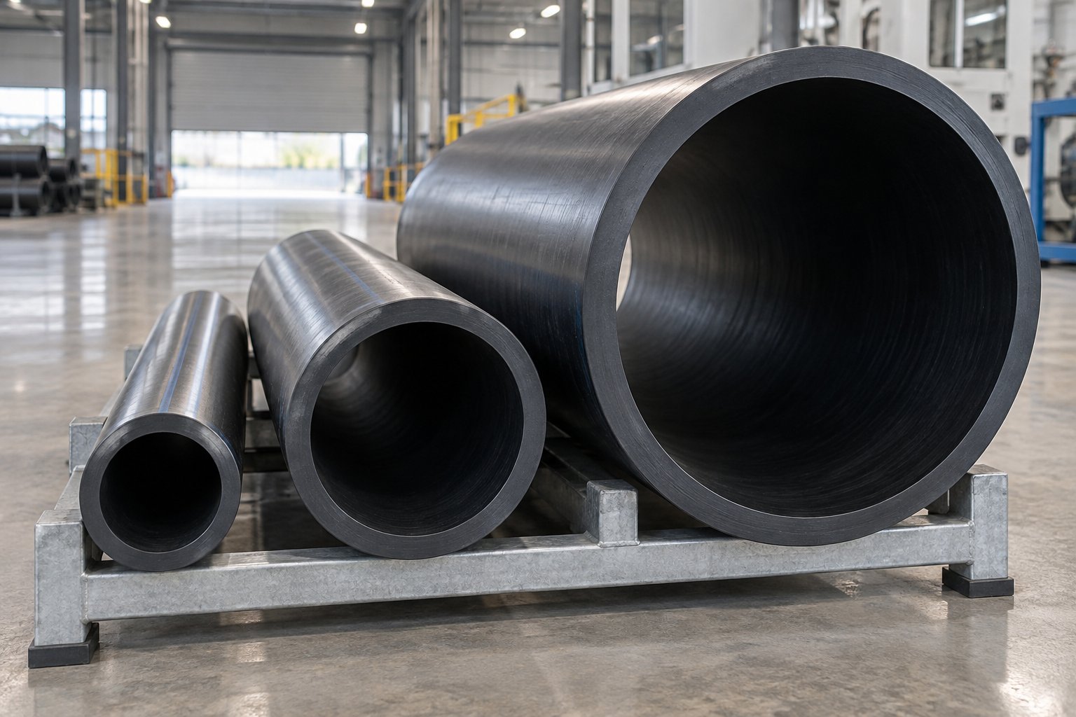
A spec sheet for a pipe extruder machine can feel like alphabet soup — L/D ratios, compression ratios, barrel zones, melt pressures, kg/h outputs. Yet every one of those numbers links directly to whether your line produces compliant pipe or generates scrap. Understanding how these parameters interrelate — and how they shift as pipe diameters scale from 16 mm residential tubing to 1600 mm infrastructure mains — is what separates a well-planned investment from an expensive mismatch.
Key Specifications Every Buyer Should Understand
When evaluating any plastic extruder machine, these are the core specifications to focus on and how they connect to each other:
- Screw diameter — The single most influential sizing parameter. A larger screw moves more material per revolution, but it also demands a proportionally larger drive motor, gearbox, and downstream equipment. Common pipe extruder screw diameters range from 45 mm for small-bore work up to 120 mm or beyond for heavy-output lines.
- L/D ratio (length-to-diameter) — Determines how much working length the screw has relative to its bore. Pipe extrusion machinery typically runs 25:1 to 40:1. A higher L/D provides more residence time, better mixing, and higher sustainable output at elevated screw speeds — which is why modern high-speed PE pipe extruders push toward 33:1 or even 40:1, as seen in Windsor's Agile series running a 40:1 L/D across all screw sizes.
- Compression ratio — The volume ratio between the deepest feed-zone channel and the shallowest metering-zone channel. It governs how aggressively the screw compacts and shears the polymer. Polyolefins typically need 3:1 to 4:1, while PVC sits closer to 2:1 to 2.5:1.
- Barrel zone temperatures — Multiple independent heating and cooling zones along the barrel let operators shape the thermal profile to match the polymer. PVC lines run tighter, lower temperature bands; HDPE lines push higher, especially in the compression zone.
- Melt pressure — Measured in bar or psi at the die entrance. Stable melt pressure means stable wall thickness. Swings in melt pressure show up as dimensional variation in the finished pipe.
- Output rate (kg/h) — The mass of polymer the extruder delivers per hour. This number scales with screw diameter and speed. For perspective, a 45 mm single screw pipe extruder may deliver 150 to 530 kg/h, while a 90 mm unit can push 600 to 1,700 kg/h.
- Line speed (m/min) — How fast the finished pipe travels through the line. Small-bore pipes run fast — sometimes exceeding 100 m/min — while large-diameter infrastructure pipe may crawl at 1 to 5 m/min because of the massive cooling and material volume involved.
Here is the critical insight: these parameters do not operate in isolation. Increasing screw diameter raises throughput capacity, but it also requires a proportionally larger drive motor and gearbox to deliver the higher torque. That higher output then demands longer vacuum tanks, more cooling capacity, and heavier haul-off units downstream. Buyers who quote only the hdpe pipe extrusion machine extruder without sizing the rest of the line around it end up with a bottleneck somewhere between the die and the stacker.
How Machine Design Scales Across Pipe Diameter Ranges
Not all pipe is created equal, and neither is the pipe extrusion machinery that produces it. The engineering requirements shift dramatically as you move from small-bore residential tubing to large-diameter infrastructure pipe. As Jinxin Extruder's technical analysis explains, a pipe extrusion line's practical size range is not just about swapping die tooling — it is the overlap of working windows across the extruder, calibrator, vacuum tank, cooling section, haul-off, and cutter.
Here is how the three major pipe diameter families differ in equipment requirements:
Small-bore pipes (16–63 mm) dominate in plumbing, irrigation, and cable conduit. These lines run at high speeds — often 15 to 120 m/min — with relatively modest extruder output. The challenge is precision: thin walls and small diameters magnify even minor process variations. Calibration tooling must be machined to tight tolerances, and the haul-off needs delicate grip pressure to avoid crushing or deforming the pipe.
Medium pipes (75–250 mm) serve pressurized water distribution, drainage, and gas networks. Output requirements climb significantly, and cooling tanks grow longer to handle thicker walls. Line speeds typically drop to 2 to 15 m/min, and haul-off units graduate from two-track to four-track configurations to distribute pulling force evenly.
Large-diameter pipes (315–1600 mm and above) are built for municipal water mains, sewer force mains, and industrial infrastructure. These lines demand the highest extruder output, the longest vacuum and cooling tanks, and multi-track haul-offs with six or eight driven pads. Line speeds slow to 1 to 5 m/min, and internal pipe cooling — delivered through the die head — becomes essential because external spray alone cannot remove heat fast enough from walls that may be 50 mm thick or more.
The table below shows how typical machine specifications scale across these three pipe diameter families:
| Parameter | Small-Bore (16–63 mm) | Medium (75–250 mm) | Large-Diameter (315–1600 mm) |
|---|---|---|---|
| Screw Diameter | 30–50 mm | 50–75 mm | 75–120+ mm |
| L/D Ratio | 25:1–33:1 | 30:1–40:1 | 30:1–40:1 |
| Output Rate | 50–300 kg/h | 200–800 kg/h | 600–1,700+ kg/h |
| Line Speed | 15–120 m/min | 2–15 m/min | 0.5–5 m/min |
| Haul-Off Tracks | 2 | 2–4 | 6–8 |
| Cooling Requirement | Short spray tanks; fast stabilization | Multi-stage spray tanks; moderate length | Extended spray tanks + internal air cooling |
One common buyer mistake is requesting the widest possible pipe range from a single line to maximize flexibility. In practice, a line quoted for 75–250 mm pipe should not be assumed to run 16 mm pipe efficiently just because the die can be changed. The extruder may deliver too much output even at minimum screw speed, the haul-off may struggle to grip such a small diameter gently, and cooling dynamics change entirely. Conversely, pushing a small-bore pvc pipe extrusion machine to produce 300 mm pipe typically stalls on output capacity long before you reach the die.
For buyers evaluating pvc extrusion machine price or any other line investment, the takeaway is clear: size your equipment around the pipe family you will produce most often, then verify that each station — not just the extruder — can handle the edges of your target range. The overlap of all those working windows defines your real production capability, and overstretching that overlap almost always costs more in scrap and downtime than investing in a properly matched second line.
Specification matching gets you the right hardware on the floor. What determines whether that hardware runs at peak efficiency for years — rather than just months — comes down to two factors that are reshaping modern pipe production: energy-saving technology and intelligent automation.
Energy Efficiency and Smart Automation in Pipe Extrusion
A perfectly specified extrusion machine means very little if it burns more electricity per kilogram than it should or relies on operators to catch dimensional drift hours after it starts. Energy consumption and process intelligence are the two areas where modern pipe lines have advanced fastest — and where most buyer evaluations still lag behind. The hardware matters, but how efficiently and intelligently that hardware runs determines your actual cost per meter of finished pipe.
Energy-Saving Technologies in Modern Pipe Extruders
Energy cost in a pipe line is not a single number — it is the sum of every motor, heater, pump, and cooling system running simultaneously. The metric that captures this holistically is specific energy consumption, measured in kWh per kilogram (or Wh/kg) of processed material. It includes both thermal energy from the heating system and mechanical energy from the extruder drive. Rollepaal's technical data puts optimized PVC extrusion at approximately 100 Wh/kg at the extruder and 15 to 25 Wh/kg at the die, with a theoretical minimum around 80 Wh/kg. Polyolefins like HDPE and PP require roughly three times more drive energy than PVC, making efficiency gains on polyolefin lines especially impactful on the bottom line.
So where do the savings come from? Several technologies are reshaping what a high-performance extrusion machine consumes on the production floor:
Direct-drive vs. gearbox-driven extruders. Traditional setups use an AC motor coupled through a gearbox to the screw. Direct-drive systems eliminate the gearbox entirely, connecting a high-torque, low-speed permanent-magnet motor straight to the screw shaft. The result is fewer mechanical losses, lower noise, reduced maintenance, and measurably better energy transfer. Not every application justifies the higher upfront cost, but for high-output lines running continuously, the payback period can be surprisingly short.
Servo motor drives. Replacing older fixed-speed motors with servo-driven systems allows the drive to match energy input precisely to real-time load demand. During steady-state production, a servo motor draws only what the plastic extrusion process actually requires — rather than running at full power regardless of load. The difference is particularly noticeable during startups and low-output runs.
Infrared barrel heaters and insulation jackets. Conventional mica-band or ceramic resistance heaters lose a significant percentage of their energy as radiated heat into the factory air. Infrared heaters deliver energy more directly to the barrel surface, and insulation jackets wrapped around heated zones prevent that energy from escaping. Together, they can reduce heating energy consumption by 20% to 40% compared to uninsulated resistance setups.
Optimized screw and cooling design. A well-balanced screw converts mechanical shear into melt heat efficiently, reducing the need for external barrel heating — and, critically, reducing the cooling energy needed to remove excess heat. Modern extruders increasingly favor air cooling and closed internal screw cooling over fluid-based systems, which cuts maintenance requirements and energy draw simultaneously. When less energy is wasted through excessive cooling, more of the available motor power goes toward useful melt preparation and throughput.
Regenerative braking on haul-offs. Haul-off motors that use regenerative drives capture kinetic energy during deceleration and feed it back into the electrical system. On lines with frequent speed changes — product changeovers, coiling transitions, or speed adjustments for wall thickness control — this recovered energy adds up over a production shift.
Lower specific energy consumption does more than cut utility bills — it can increase effective line capacity. When less motor power is consumed by inefficient heating and cooling, that recovered capacity allows higher throughput from the same extruder size.
Automation and Smart Control Systems
Energy efficiency addresses how much power the line draws. Automation addresses how consistently — and how intelligently — it uses that power to produce in-spec pipe. The shift from manual adjustment to closed-loop, sensor-driven control is the single biggest differentiator between extrusion manufacturing operations that run lean and those that burn margin on scrap, overweight pipe, and unplanned downtime.
Imagine a production run where the operator sets the line at startup and walks away for eight hours. Sounds risky? With modern automation, it is increasingly routine. Here are the key technologies making that possible on today's high-performance extruders and complete pipe lines:
- Gravimetric dosing systems — Weigh raw material in real time and adjust feed rates automatically to maintain exact recipe ratios. Unlike volumetric feeders that meter by volume alone, gravimetric systems compensate for bulk density variations in powder or regrind, ensuring consistent material usage and eliminating recipe drift across shifts. As Bausano's Industry 4.0 implementation highlights, these feeders are fully digitally controlled and require no manual calibration before operating.
- Ultrasonic wall thickness measurement — Scanners mounted after the cooling section continuously measure wall thickness at multiple points around the pipe circumference. This data feeds directly into haul-off speed and die-head temperature controllers for automatic correction — catching dimensional drift in seconds rather than meters of out-of-spec pipe.
- Centralized PLC and HMI interfaces — A single programmable logic controller (PLC) with a human-machine interface (HMI) touchscreen gives operators unified visibility and control over every station from feeder to cutter. This eliminates the guesswork of adjusting isolated stations independently.
- Automatic dimension correction — Closed-loop systems link wall thickness and diameter readings to extruder speed, haul-off speed, and die-zone temperatures. When a measurement drifts toward a tolerance limit, the system corrects in real time without operator intervention.
- Recipe management for quick changeover — Stored product recipes let operators switch between pipe sizes or materials with a single selection, automatically loading validated temperature profiles, screw speeds, haul-off settings, and dosing ratios. This slashes changeover time and eliminates the startup scrap that comes from manually dialing in a new product.
- Data logging and production analytics — Every process parameter — temperatures, pressures, speeds, output weights, dimensional readings — is logged continuously. This historical data enables trend analysis, root-cause investigation when quality deviates, and predictive maintenance scheduling based on actual operating hours rather than calendar intervals.
- Remote monitoring and support — Connected extrusion tech platforms allow equipment suppliers to access machine diagnostics remotely, diagnose issues without a site visit, and push software updates — reducing downtime and accelerating troubleshooting.
The practical impact of these systems is measurable. Scrap rates drop because dimensional deviations are caught and corrected within seconds. Material costs fall because automated wall-thickness control eliminates the habitual overweight that manual lines build in as a safety margin. Consistency improves because validated recipes remove operator-to-operator variability. And per-unit production costs decline because the line runs closer to its theoretical maximum for more hours per shift.
For any buyer evaluating a pipe line investment, energy efficiency and automation are no longer premium add-ons — they are baseline requirements for competitive extrusion manufacturing. The lines that pay for themselves fastest are the ones that waste the least power and the least material, shift after shift, with minimal human intervention.
These efficiency gains apply to single-layer pipe production, but a growing segment of the market demands something more complex: pipes with multiple functional layers, each contributing a distinct performance property. That multilayer capability introduces new equipment requirements — and new decisions about component selection — that round out the full picture of modern pipe extrusion.
Multilayer Pipe Technology and Choosing the Right Components
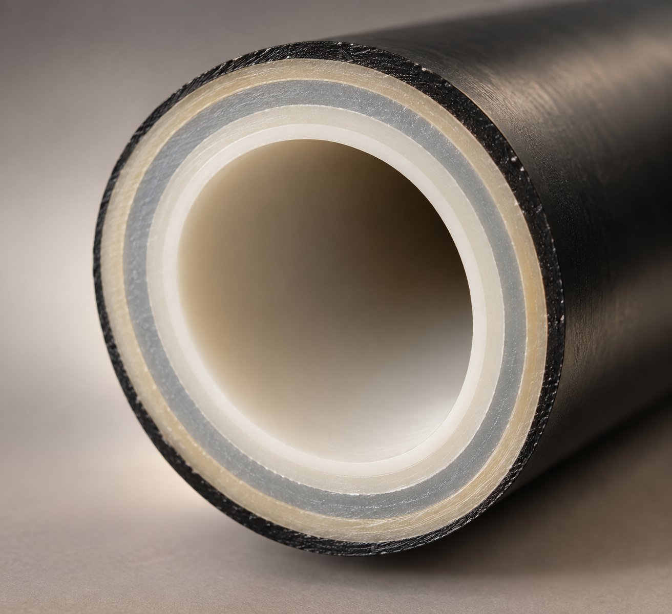
A single-layer HDPE water pipe or PVC drainage pipe covers the majority of pipe extrusion output worldwide — but it cannot solve every engineering problem. What happens when a radiant heating system needs an oxygen barrier to protect metal components from corrosion? Or when a drainage stack needs acoustic damping without adding excessive weight? Or when a hot-water pipe needs glass-fiber reinforcement to handle higher pressure at elevated temperatures? Single-layer plastics extrusion hits a wall. Co-extrusion — running multiple extruders into a single die to produce pipes with distinct functional layers — is the technology that breaks through it.
Co-Extrusion and Multilayer Pipe Innovation
The concept behind co-extrusion is deceptively simple: instead of feeding one plastic extrusion machine into the die, you feed two, three, or even five separate extruders — each processing a different material — into a multilayer die head that merges their melt streams into concentric layers within a single pipe wall. The execution, however, demands precise synchronization of output rates, melt temperatures, and layer adhesion chemistry across every extruder simultaneously.
Consider a few real-world examples that illustrate why this complexity pays off:
- PE-RT pipes with EVOH oxygen barrier layers — Used extensively in radiant floor heating systems, these pipes feature a three-layer or five-layer structure. The PE-RT inner and outer layers provide flexibility, pressure resistance, and temperature tolerance, while the thin EVOH (ethylene vinyl alcohol) middle layer blocks oxygen permeation into the heating loop. Without this barrier, dissolved oxygen corrodes metal boiler components and circulator pumps, dramatically shortening system life. SHARC's technical analysis of floor heating pipe production notes that five-layer EVOH-barrier PE-RT lines are now standard for commercial and residential heating applications, with adhesive tie layers bonding the EVOH to the PE-RT substrate on both sides.
- Foam-core PVC pipes for noise reduction — Three-layer PVC pipes with a physically or chemically foamed middle layer reduce weight by up to 30% compared to solid-wall equivalents while significantly dampening sound transmission — a critical requirement in multi-story residential drainage stacks. WEBER's PVC pipe extrusion systems specifically address foam-core and highly filled sound-insulating pipes as a core capability, using multilayer die heads with independently controlled distributor channels for each layer.
- Fiber-reinforced PP-R pipes for higher pressure ratings — PP-R pipes with a glass-fiber-reinforced core layer achieve pressure ratings that plain PP-R cannot reach at the same wall thickness. The reinforced core reduces thermal expansion — a persistent challenge with polypropylene — while the unreinforced inner and outer skins maintain smooth surfaces for fluid flow and chemical resistance.
Each of these multilayer structures requires its own co-extrusion die design, with separate flow channels for each layer that merge at precisely controlled positions inside the die body. Layer thickness ratios must remain consistent across the full production run, which means every extruder in the system needs stable, repeatable output — any fluctuation in one extruder shows up as a layer-thickness variation in the finished pipe.
The equipment footprint grows accordingly. A five-layer PE-RT oxygen-barrier line, for instance, uses a main PE-RT extruder, a smaller EVOH extruder, two adhesive-layer extruders, and a second PE-RT extruder — all feeding a single multilayer die head. Floor space, electrical infrastructure, and operator training requirements all increase. But for plastic extrusion manufacturers targeting high-value market segments like heating systems, acoustic drainage, and high-pressure plumbing, the performance advantages of multilayer pipe make the added complexity a competitive necessity rather than an optional upgrade.
Co-extrusion also opens the door to incorporating recycled material in non-critical layers. A common strategy uses virgin resin for the inner and outer pipe surfaces — the layers that contact media and face inspection — while routing regrind or recycled content into the core layer where cosmetic and surface-quality requirements are lower. This approach cuts raw material costs and supports sustainability goals without compromising the pipe's functional performance. As Conair's tooling selection guide describes, the most typical multilayer pipe uses a center layer of regrind sandwiched between two virgin-material layers delivered from separate extruders into a multilayer die.
Selecting the Right Extruder Components for Your Production Goals
Whether you are building a single-layer polyolefin line, a conical twin-screw PVC system, or a multilayer co-extrusion setup, the component selection process follows the same logic: start with your material and your target pipe, then work outward through every station to make sure each one matches. Sounds straightforward, but most buyer mistakes happen when one component is sized in isolation — an oversized extruder paired with an undersized cooling section, or a high-output die feeding a haul-off that cannot keep pace.
Here is a prioritized checklist that walks through the key decisions in order:
- Define your target material and pipe specifications first. Everything flows from this. PVC dry blend requires a conical twin screw; HDPE pellets pair with a single screw. Pipe diameter range, wall thickness, and production standard (ASTM, ISO, DIN) set the baseline for every downstream decision.
- Match screw and barrel to your material and output requirements. Select the screw geometry — compression ratio, L/D ratio, flight design — based on the polymer's thermal sensitivity and crystallinity. Barrel construction must match the resin's abrasiveness and processing temperature: nitrided steel for standard applications, bimetallic liners for filled or recycled materials. For operators sourcing precision barrel components, working with a specialized manufacturer ensures material compatibility and dimensional accuracy. NANHAIYA offers custom-engineered and replacement single screw barrels tailored to specific pipe extrusion requirements — along with configurations for film, sheet extrusion, pelletizing, and recycling lines — making them a practical resource when upgrading worn barrels or building a new screw-barrel combination from scratch.
- Choose die tooling for your pipe diameter range and layer structure. Determine whether a spider, spiral mandrel, or basket die fits your surface-quality and weld-line requirements. For multilayer applications, ensure the die head accommodates the correct number of extruder inlets with independently controlled flow channels. Verify that interchangeable die and mandrel sets cover your anticipated product mix without overstretching the die's practical operating range.
- Size downstream equipment to your maximum production speed. Vacuum calibration tank length, cooling tank capacity, haul-off track count, and cutter cycle time must all handle your peak output rate — not just your average. A line that bottlenecks at the cooling section during high-output runs produces more scrap than one running at a slightly lower but fully supported throughput.
- Plan for future product diversification. If multilayer production, larger pipe diameters, or new materials are on your three-to-five year horizon, factor that into your initial equipment selection. Adding a co-extrusion station later is far easier when the die head, control system, and floor layout were designed with expansion in mind. Similarly, selecting a screw and barrel platform with proven custom plastic extrusion capabilities — rather than a fixed, one-size design — gives you the flexibility to retool for new polymers without replacing the entire extruder.
- Evaluate automation and energy efficiency as standard requirements. Gravimetric dosing, ultrasonic wall measurement, closed-loop dimensional correction, and recipe management are no longer premium options. They are the systems that protect your margin on every meter of pipe produced. Budget for them upfront rather than retrofitting later.
Component selection is ultimately a system-level exercise. The best plastic extrusion machines on the market still underperform when paired with mismatched tooling, undersized cooling, or a barrel bore worn beyond tolerance. Conversely, a well-matched line — where each station's working window overlaps cleanly with every other — delivers consistent quality at lower cost per meter, shift after shift, with fewer unplanned stops.
For buyers navigating this process, the single most important takeaway from this entire anatomy breakdown is this: a pipe extrusion line is only as strong as its weakest station. Evaluate every component with the same rigor you apply to the extruder itself, source critical wear components like screws and barrels from manufacturers who engineer for your specific material and application, and invest in the control systems that keep the whole line running in spec without constant manual intervention. That is how you build a production floor that performs — not just on day one, but for years of continuous operation.
Frequently Asked Questions About Plastic Pipe Extrusion Machines
1. What is a plastic pipe extrusion machine and how does it work?
A plastic pipe extrusion machine is an integrated production system that converts raw thermoplastic material — pellets or powder — into continuous hollow pipe profiles. It works by feeding resin into a heated barrel where a rotating screw melts and pressurizes the polymer, then forces the molten material through an annular die head that shapes it into a tube. Immediately after the die, vacuum calibration tanks lock in the pipe's outer diameter, spray cooling baths solidify the wall, a haul-off unit pulls the pipe forward at a controlled speed, and a cutting station trims it to length. Each station in this sequence directly influences the dimensional accuracy and quality of the finished product.
2. What is the difference between single screw and twin screw extruders for pipe production?
The choice between single screw and twin screw extruders depends primarily on the polymer being processed. Single screw extruders are the standard for polyolefins like HDPE, PP, and PE-RT because these materials arrive as pre-compounded pellets that only need melting and pressurizing. Conical twin screw extruders are required for rigid PVC pipe because PVC is processed from dry-blend powder and is thermally sensitive — twin counter-rotating screws provide the gentle, low-shear plasticization PVC demands without triggering degradation. Parallel twin screw extruders serve specialty compounding and high-filler applications but are rarely used for direct pipe extrusion. Matching the wrong extruder type to your material leads to thermal degradation, inconsistent output, or both.
3. How does screw and barrel design affect pipe quality?
Screw geometry — including the compression ratio, L/D ratio, and channel depth across the feed, compression, and metering zones — determines how uniformly and gently the polymer is melted. A screw designed for HDPE uses a higher compression ratio (3:1 to 4:1) than one for PVC (2:1 to 2.5:1) because PVC degrades under excessive shear. Barrel condition is equally critical: worn barrel bores increase the screw-to-barrel clearance beyond the typical 0.1 to 0.6 mm tolerance, allowing melt backflow that reduces output and introduces temperature inconsistencies. The result of mismatched or worn screw-barrel combinations shows up as burn marks, uneven wall thickness, surface roughness, and compromised pressure ratings in the finished pipe. Specialized suppliers like NANHAIYA offer custom and replacement single screw barrels engineered for specific pipe materials and extrusion line requirements.
4. What downstream equipment is needed for a complete pipe extrusion line?
A complete pipe extrusion line requires several downstream stations beyond the extruder and die head. These include a vacuum calibration tank with a precision sizing sleeve that locks in the pipe's outer diameter, multi-stage spray cooling baths for gradual temperature reduction, caterpillar or belt-type haul-off units that pull the pipe at a controlled speed to maintain wall thickness, a marking station for printing or embossing product identification, and a cutting system — typically a planetary saw for rigid pipe or an automatic coiler for flexible pipe. Inline belling machines can also form pipe joint sockets without a secondary operation. Together, these stations control outside diameter tolerance, wall thickness uniformity, ovality, cut squareness, and surface finish.
5. What are the benefits of co-extrusion in multilayer pipe production?
Co-extrusion enables pipe manufacturers to combine multiple materials in distinct functional layers within a single pipe wall. For example, PE-RT pipes with an EVOH oxygen barrier layer prevent corrosion in radiant heating systems, foam-core PVC pipes reduce weight and dampen sound in drainage stacks, and glass-fiber-reinforced PP-R pipes achieve higher pressure ratings with reduced thermal expansion. Co-extrusion also allows processors to route recycled or regrind material into non-critical core layers while maintaining virgin-quality inner and outer surfaces. Although co-extrusion lines require multiple synchronized extruders and specialized multilayer die heads, the resulting performance advantages open access to high-value market segments that single-layer pipe cannot serve.
Written by
Nanhaiya Technical Team
Zhoushan Nanhaiya Plastic Machinery Co., Ltd.
The Nanhaiya technical team supports screw and barrel manufacturing projects through application review, technical communication, custom manufacturing coordination, and production and quality control.
Discuss Your Application
Related Articles
More insights on screw barrel technology and plastics processing.
Blown Film Problems Decoded: What Your Bubble Is Telling You
Oct 23, 2026
Solve blown film problems from resin to roll. Learn to identify gels, gauge variation, bubble instability, die defects, and downstream failures with actionable fixes.
Read Article
WPC Decking Extrusion Line Decoded: From Raw Resin To Finished Board
Oct 23, 2026
Learn how a WPC decking extrusion line works — from raw material compounding and extruder selection to process parameters, troubleshooting defects, and line layout planning.
Read Article
Single Screw Extruder Barrel Wear: Spot It, Measure It, Stop It
Oct 23, 2026
Learn how to spot, measure, and stop single screw extruder barrel wear. Zone-by-zone analysis, wear mechanisms, diagnostic symptoms, and repair vs. replace guidance.
Read ArticleLooking for something else?
Search by material, symptom or product and jump straight to the relevant page.
These are navigation suggestions based on keyword matching — not a quotation, not a delivery commitment, and not a substitute for engineering review. Final specification is confirmed by our engineers against your drawings and processed material.
Need help with screw barrel selection?
Share your machine model, processed material and application. Our team can help with pricing and technical support.