

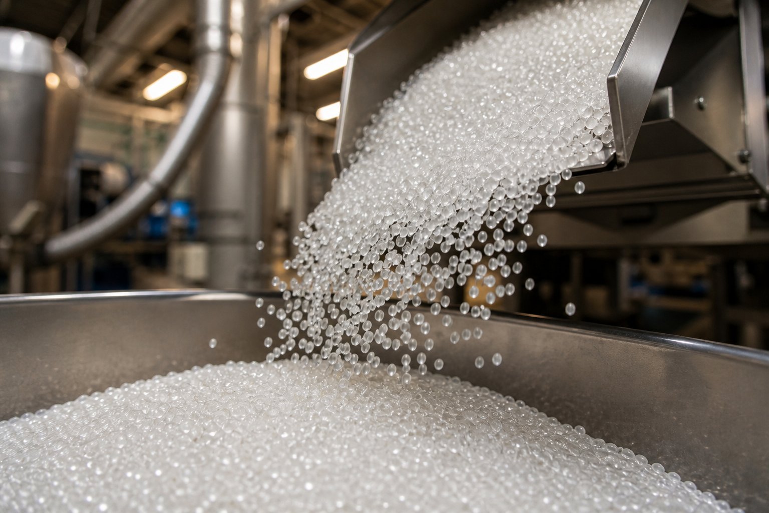
What Is Plastic Pelletizing and Why It Matters
Imagine a factory floor where injection molders, film extruders, and blow molders all need to run at peak speed with zero surprises. What do they all demand as input? Not random flakes, not dusty powder, not tangled film scraps — they need small, uniform pellets that melt predictably, feed consistently, and flow without a hitch. That demand is exactly why plastic pelletizing exists.
Plastic pelletizing is the thermomechanical process of converting raw or recycled plastic — whether it arrives as shredded flakes, fine powder, off-spec parts, or post-consumer film — into uniform, free-flowing pellets typically measuring 2 to 5 mm in diameter. Inside an extruder, the material is melted through a combination of controlled heating and intense mechanical shear, filtered to remove contaminants, pushed through a die plate, cut into small pieces, and cooled into solid granules with consistent geometry and bulk density. The result is a standardized feedstock ready for virtually any downstream manufacturing process.
This guide breaks the full process wide open — from material preparation and extrusion through cutting methods, equipment selection, resin-specific challenges, quality metrics, and hands-on troubleshooting — so you can identify the exact gaps that compromise pellet quality in your operation.
What Plastic Pelletizing Means in Manufacturing
At its core, pelletizing is a shaping step. You'll sometimes hear it used interchangeably with terms like "pelletization" or see it phrased as "to pelletize," but the pelletizing meaning stays the same: transforming irregular polymer material into a geometrically consistent, easy-to-handle form. It is important to distinguish this from compounding, which is the formulation step — blending a base resin with additives, colorants, fillers, or reinforcements to create a customized material recipe. Compounding changes what the plastic is; pelletizing changes what the plastic looks like physically. In practice, both steps often happen on the same extrusion line, with compounding feeding directly into pelletizing. Yet they remain fundamentally different operations, and confusing the two leads to mismatched equipment choices and process errors.
Why Pellets Are the Industry Standard
So what is pelletizing actually solving? Picture the alternative: feeding shredded film with a bulk density around 0.1 to 0.2 g/cm³ into a high-speed injection molder. The material bridges in the hopper, feeds erratically, and melts unevenly — a recipe for rejected parts and lost production hours. Pellets eliminate every one of those problems. Here is why they dominate:
- Consistent bulk density — pellets reach 0.4 to 0.7 g/cm³, enabling precise gravimetric feeding and reliable hopper flow.
- Uniform melting behavior — consistent size means consistent heat absorption, which translates to stable melt pressure and fewer defects.
- Dust-free handling — unlike powders or fines, pellets create minimal airborne particles, improving workplace safety and housekeeping.
- Efficient storage and transport — higher density means more material per container, cutting freight costs and warehouse footprint.
- Automation compatibility — pellets move predictably through conveyors, vacuum loaders, and blending stations without bridging or rat-holing.
Pellets are the universal currency of the plastics supply chain — every molder, extruder, and blow molder on the planet is designed to accept them, making pellet form the single point of standardization that connects resin producers to finished-goods manufacturers.
Yet producing pellets that actually meet downstream specifications is far harder than the concept suggests. The difference between a pellet that runs flawlessly in a molder and one that causes gel defects, feeding inconsistencies, or color drift comes down to process details most operators never examine closely enough — starting with the step-by-step workflow that turns raw polymer into finished granules.
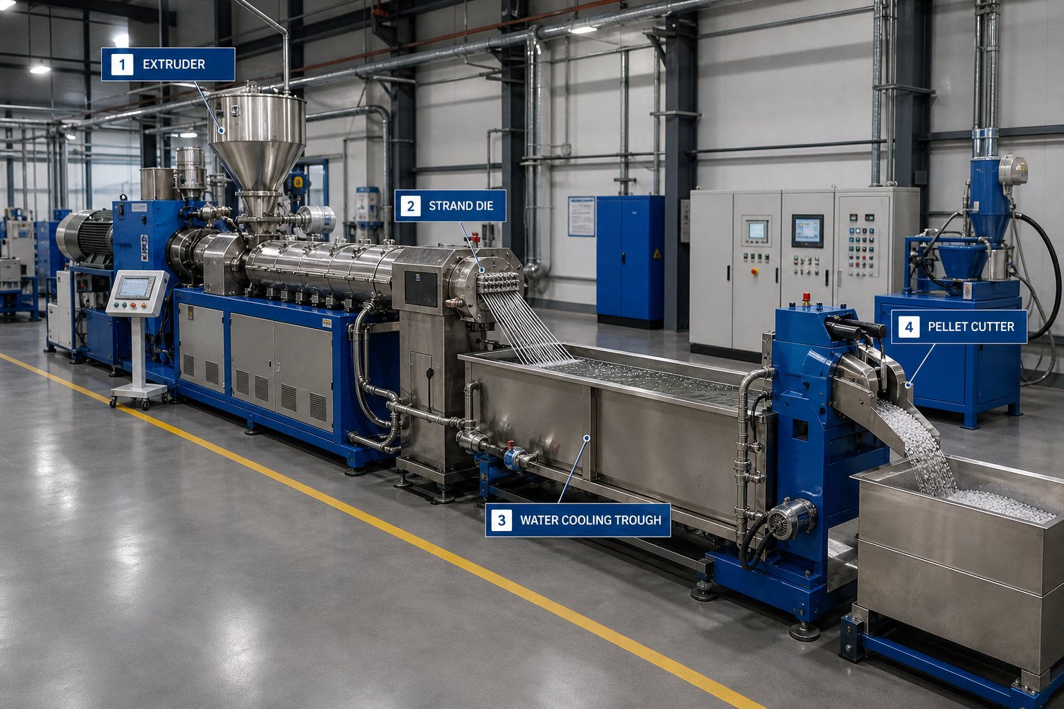
The Complete Pelletizing Process From Start to Finish
Most descriptions of the pelletizing process boil everything down to three or four vague steps: melt, extrude, cut, cool. That shorthand hides the stages where quality actually gets made — or lost. Each phase in the workflow acts as a quality gate, and a problem that starts upstream (say, excess moisture in the feed) only reveals itself much later as bubbles, voids, or brittle pellets that buyers reject.
Here is the full pelletization process laid out in sequence, covering every named stage from raw material to packaged product:
- Collection, sorting, and contamination removal
- Size reduction (shredding or grinding)
- Washing (for recycled feedstock)
- Pre-drying and moisture control
- Feeding (volumetric or gravimetric) into the extruder
- Extrusion — melting, mixing, and pressurizing
- Degassing and venting of volatiles
- Melt filtration via screen changer
- Die extrusion through a die plate
- Cutting into pellets (strand, underwater, die-face, etc.)
- Cooling (water bath, water ring, or air system)
- Pellet drying
- Classification and screening
- Dedusting
- Blending and homogenization in silos
- Conveying and packaging
Sounds like a lot of steps? It is — and skipping or underestimating any one of them is exactly how quality gaps form. Let's walk through each phase in detail.
Material Preparation and Feeding
Everything starts before the extruder ever heats up. For recycled feedstock, the first priorities are sorting by polymer type and color, shredding or grinding the material into uniform flakes (typically 5 to 12 mm), and washing to remove labels, adhesives, dirt, and oils. Clean, consistent flake size means the extruder receives a steady feed instead of surging through oversized chunks and starving on fines.
Pre-drying is the step most responsible for downstream problems when it's done poorly. Hygroscopic resins like PET and PA absorb atmospheric moisture that turns into steam inside the barrel. That steam creates bubbles, degrades the polymer chain through hydrolysis, and produces weak, discolored pellets. PET, for example, needs to be dried below 50 ppm moisture content before it ever touches a screw. Even non-hygroscopic polymers like PE benefit from surface moisture removal — residual water destabilizes melt pressure and causes die drool.
Feeding itself matters more than many operators realize. Volumetric feeders deliver material by volume and work fine for uniform pellets, but for irregular flakes, films, or powders, gravimetric feeders measure actual mass per unit time. The difference shows up directly in melt consistency: an erratic feed rate produces pressure swings in the barrel, and those swings propagate all the way to pellet size variation at the cutter.
Extrusion, Degassing, and Melt Filtration
Once material enters the extruder barrel, three things happen in rapid succession: the polymer melts through a combination of external heating and shear friction from the rotating screw, the melt is homogenized into a uniform mass, and it's pressurized to push through the downstream die. The screw design — its flight depth, compression ratio, and mixing elements — determines how effectively these three functions occur.
Trapped air, residual moisture, and volatile organic compounds don't just disappear on their own. The degassing zone — a vented section of the barrel connected to either atmospheric or vacuum extraction — provides an escape route for these gases. Without adequate venting, volatiles remain suspended in the melt, showing up as internal voids or surface porosity in the finished pellet. Recycled materials with prior heat history or residual contamination demand especially aggressive degassing, often through multiple vent ports and deep vacuum.
Between the extruder and the die sits one of the most overlooked components in the entire line: the screen changer. This filtration system uses layers of woven wire mesh mounted on a breaker plate to physically block contaminants — carbonized fragments, gels, metal particles, unmelted material — from reaching the die and ending up embedded in your pellets as black specks or surface defects.
What many operators miss is that the screen pack does double duty. Beyond catching particles, it generates backpressure that helps the screw's metering section deliver more uniform shear and mixing. As contamination accumulates, that backpressure climbs progressively — and when you swap in a fresh screen, pressure drops suddenly. This pressure event propagates through the melt stream, causing a brief window of inconsistent output and off-spec pellets.
Two main approaches address this trade-off:
- Discontinuous (manual) screen changers — simple slide-plate or bolt designs that require slowing or stopping the line for each change. They're cost-effective for clean feedstock where changes are infrequent, but every swap produces a pressure disruption and a scrap segment.
- Continuous screen changers — dual-station or hydraulic designs that replace one filter section while the other stays in the melt stream, minimizing pressure fluctuation. These are essential for recycling lines processing contaminated post-consumer material where screen loading is rapid and frequent.
Choosing the wrong type doesn't just affect uptime — it directly impacts pellet purity and dimensional consistency across every production run.
Die Extrusion, Cutting, Cooling, and Post-Processing
The filtered, degassed melt is pushed through a die plate — a precision-machined steel disc with multiple small holes that shape the polymer into strands, droplets, or direct pellet forms depending on the cutting method used. Die hole diameter, land length, and the number of orifices all influence pellet geometry and throughput capacity. (The specific cutting methods — strand, underwater, water ring, and others — each deserve their own detailed comparison, covered in the next section.)
Cooling rate is far from a minor detail. It governs the crystallinity, internal stress, and surface finish of the final pellet — and different polymers respond very differently. A semi-crystalline resin like PET develops its crystalline structure during cooling, and the rate at which that happens determines whether the pellet is brittle, hazy, or properly conditioned for downstream use. Amorphous polymers like PS or ABS are less sensitive to cooling rate but can develop surface cracking if quenched too aggressively. Common cooling systems include water baths for strand pelletizing, pressurized water circuits for underwater systems, water rings for die-face cutting, and air cooling for moisture-sensitive materials.
Here is where most guides end — and where critical quality-defining operations actually continue. The post-pelletizing stages are the difference between raw output and a finished, sellable product:
- Pellet drying — centrifugal or fluidized-bed dryers remove surface moisture picked up during water cooling, preventing clumping in storage and ensuring accurate moisture specs for buyers.
- Classification and screening — vibrating screens separate oversized pellets, undersized fines, and agglomerates from the target size fraction, tightening the pellet size distribution that downstream processors demand.
- Dedusting — dedusting systems remove fine particles and streamers generated during conveying and cutting. These contaminants may seem minor, but dust causes surface blurring on finished products, gel formation in films, and burn marks in injection molds.
- Blending and homogenization — large silos with internal mixing gently blend multiple production batches together, smoothing out any lot-to-lot variation in color, melt flow index, or additive concentration.
- Conveying and packaging — pneumatic or mechanical conveyors move finished pellets to packaging stations where they're loaded into bags, boxes, or bulk containers for shipment.
Each of these post-processing steps targets a specific quality metric that pellet buyers actually measure — size distribution, moisture content, dust levels, lot consistency. Skip any of them, and the deficiency shows up not in your plant, but in your customer's rejection report.
Of course, understanding the full workflow is only half the equation. The method you choose for the cutting and cooling step — strand, underwater, water ring, hot die face, or air-cooled — reshapes everything from pellet geometry to throughput ceiling and capital cost, and picking the wrong one for your resin is one of the fastest ways to tank quality at scale.
Five Pelletizing Methods Compared With Selection Matrix
The cutting and cooling method you select doesn't just influence pellet shape — it dictates throughput capacity, automation potential, material compatibility, and the total capital you'll invest. Five distinct pelletizing systems dominate the market, and each one was engineered to solve a different set of processing constraints. Choosing the wrong system for your resin and production profile quietly erodes quality in ways that only surface when downstream customers start rejecting shipments.
Let's break each method down by how it actually works, where it excels, and where it falls short.
Strand and Underwater Pelletizing Explained
Strand pelletizing is the most widely used and cost-effective approach, especially for rigid polymers processed by toll compounders and in-house operations running frequent product changes. The process is straightforward: molten polymer exits a multi-hole strand die, forming continuous cylindrical strands that travel through a water bath or cooling trough. After solidifying, the strands pass through a de-watering unit or air knife and enter a rotary cutter, where spinning blades slice them into short cylindrical pellets. A classifier downstream removes any oversized pieces or agglomerates.
The simplicity is both the strength and the weakness. Strand systems are easy to clean, fast to change over between materials, and offer direct visual access to the melt — you can literally watch strand quality as the line runs. However, strand pelletizing is more labor-intensive than alternatives. Imagine stringing up to 75 individual strands over and under guide rolls every time you start a new job. Process variations can cause strand breakage, and because cutting happens on solidified material, there's greater cutter wear and more dust and fines generation compared to die-face methods. The water bath also creates a larger floor footprint than compact die-face pelletizing systems.
Underwater pelletizing (UWP) takes the opposite approach. Cutting happens immediately at the die face while the polymer is still molten. A set of rotating blades shears droplets directly off the die holes, and a pressurized water stream flooding the cutting chamber instantly carries these droplets away. Surface tension forces shape each droplet into a near-perfect sphere as it solidifies — a geometry unique to this pelletizing technology.
The process water transports the spherical pellets to an agglomerate catcher, then on to a centrifugal dryer. Because everything moves through enclosed piping rather than open troughs, the dryer and water-treatment equipment can sit in a different room or even on a separate floor — a significant advantage for plant layout flexibility. UWP systems offer the highest throughput capacity among all pelletizing methods, reaching up to approximately 70,000 lb/hr, versus roughly 44,000 lb/hr for strand systems. They also deliver the broadest material versatility, handling everything from standard polyolefins to hot melts, masterbatches, and sticky compounds that strand systems can't manage.
The trade-off? UWP is the most complex and capital-intensive pelletizing system available. It also carries a risk of die "freeze-off" — when upstream process variations reduce or unevenly distribute polymer flow at the die plate, causing the melt to solidify inside the die holes. Maintaining consistent, high melt pressure at the die is essential to prevent this disruption.
Water Ring, Hot Die Face, and Air-Cooled Methods
Water ring pelletizing sits in a middle ground between strand and underwater systems. Like UWP, it's a die-face pelletizer — rotating knives cut the molten polymer as it exits the die holes. The difference lies in the cooling mechanism: instead of a fully flooded cutting chamber, the freshly cut pellets are flung outward by centrifugal force into a ring of water that flows tangentially around the chamber's perimeter. This water ring cools the pellets and transports them to a trough for additional cooling before they reach a centrifugal dryer.
The result is a compact, moderately automated pelletizing system that costs less than UWP and resists die freeze-off far better. Pellet geometry is rounded but flat — think of a small aspirin tablet, sometimes described as lenticular. The limitation? Water ring systems work best with high-melt-strength materials like polyolefins and polystyrene. They struggle with high-heat or sticky polymers and top out at roughly 11,000 lb/hr — considerably less than either strand or underwater systems.
Hot die face pelletizing is a specialized method designed for materials that remain tacky or semi-solid at room temperature, such as hot-melt adhesives, waxes, bitumen, and certain thermoplastic elastomers. The polymer is cut at the die face, but instead of immediate water quenching, the pellets are cooled more gradually — often on a cooling conveyor belt — to avoid trapping surface moisture that would compromise the end product. This controlled, slower cooling makes it unsuitable for high-throughput commodity resins but indispensable for niche formulations where water contact is unacceptable.
Air-cooled die face pelletizing replaces water entirely with forced-air cooling. After the rotating blade cuts the melt at the die, the pellets drop onto a vibrating conveyor or fluidized-bed cooler where ambient or chilled air removes heat. This approach is purpose-built for moisture-sensitive materials — certain engineering resins, reactive compounds, and specialty additives that degrade or absorb water on contact. Throughput and cooling efficiency are lower than water-based methods, but for applications where even trace surface moisture is a disqualifier, air cooling is the only viable option.
Pelletizing Method Comparison Matrix
Choosing among these five pelletizing systems means weighing material compatibility, production volume, pellet geometry, budget, and maintenance tolerance all at once. The matrix below puts every critical variable side by side so you can evaluate trade-offs at a glance:
| Method | Suitable Materials | Throughput Range | Pellet Shape | Capital Cost | Maintenance Complexity | Cooling Mechanism |
|---|---|---|---|---|---|---|
| Strand Pelletizing | Most rigid polymers (PE, PP, PS, ABS, PA, PET, PVC); ideal for frequent changeovers | Up to ~44,000 lb/hr | Cylindrical | Low | Low — but labor-intensive startup (strand threading) | Water bath or water slide |
| Underwater (UWP) | Virtually all polymers including hot melts, masterbatches, sticky compounds, and expandable resins | Up to ~70,000 lb/hr | Spherical | High | High — PLC-controlled, requires precise water-system management | Pressurized water in flooded cutting chamber |
| Water Ring | High-melt-strength materials (polyolefins, PS); not for high-heat or sticky polymers | Up to ~11,000 lb/hr | Lenticular (rounded, flat) | Medium | Medium — compact system, moderate automation | Tangential water ring plus cooling trough |
| Hot Die Face | Hot-melt adhesives, waxes, bitumen, certain TPEs | Low to moderate | Hemispherical to lenticular | Medium | Medium — blade and die maintenance similar to UWP | Cooling conveyor belt (air or misting) |
| Air-Cooled Die Face | Moisture-sensitive resins, reactive compounds, specialty additives | Low to moderate | Lenticular to spherical | Medium | Low to medium — no water system to maintain | Forced air, vibrating conveyor, or fluidized bed |
Why does pellet geometry matter this much? Because downstream processors aren't indifferent to shape. Spherical pellets from underwater systems offer the highest bulk density and the most uniform hopper flow, making them preferred by large-scale film producers and blow molders who need extremely consistent melt delivery. Cylindrical pellets from strand cutting are perfectly acceptable for most injection molding applications, but their flat ends can occasionally stick together and cause bridging in narrow feed throats. Lenticular pellets from water ring systems fall in between — adequate for many applications but less predictable in automated conveying systems due to their flat profile.
Film producers tend to favor spherical pellets for tight melt-flow tolerances and minimal gel counts. Injection molders typically prioritize consistent size and uniform bulk density over shape. Blow molders, particularly those running large parisons, need reliable crystallinity and consistent melting — properties heavily influenced by how the pellet was cooled and at what rate, which circles back to the cooling mechanism each system uses.
Matching the right pelletizing system to your specific resin, throughput target, and end-market requirements is the first strategic decision. The second — and equally impactful — decision involves the extrusion hardware feeding that system, starting with the extruder itself and the wear components that determine whether your line delivers consistent output for months or starts drifting after weeks.
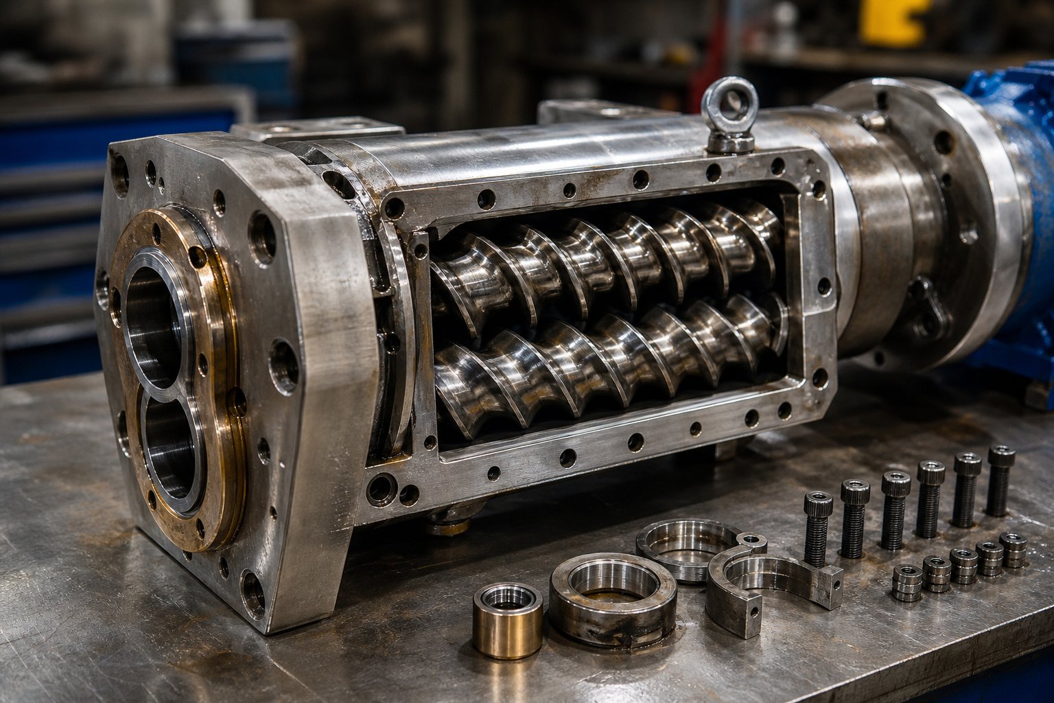
Extruder Types and Critical Line Components
Every pelletizing method described above — strand, underwater, water ring, or die face — depends on one upstream machine to deliver a perfectly homogenized, pressurized, contaminant-free melt stream. That machine is the extruder. Get the extruder wrong, and even the most sophisticated pelletizer head can't compensate. Inconsistent melt temperature, poor additive dispersion, trapped volatiles, and erratic pressure all originate inside the barrel, and they all show up as defects in the finished pellet.
So what is a pelletizer without a properly matched extruder? Just an expensive cutting tool waiting for a melt stream that never arrives at spec. Choosing the right plastic pelletizing equipment starts here — with the extruder type, screw configuration, and the wear components that determine how long your line holds its performance edge.
Single-Screw vs. Twin-Screw Extruders for Pelletizing
Think of this as a question of task complexity. A single-screw extruder uses one rotating screw inside a heated barrel to convey, melt, and pressurize the polymer. Material moves forward through drag flow — friction between the pellets and the barrel wall generates the forward push. This mechanism is inherently simple, reliable, and cost-effective. It's the right choice when you're re-pelletizing pre-compounded material that's already formulated and just needs to be reshaped, or when you're running high-volume, single-resin production where intensive mixing isn't required.
When the job gets more complex — blending multiple additives into a base resin, producing color masterbatch, processing recycled feedstock with contaminants and variable melt flow — a co-rotating twin-screw extruder becomes essential. Two intermeshing screws rotate in the same direction, creating a combination of shear, elongational flow, and positive displacement that single-screw machines simply cannot replicate. The result is far more intensive mixing, better additive dispersion, and superior degassing capability. You'll find co-rotating twin-screw extruders at the heart of nearly every compounding operation, masterbatch production line, and serious recycling facility.
There's a third option that fewer operators consider: counter-rotating twin-screw extruders, where the two screws turn in opposite directions. These generate lower shear forces and gentler material handling, which makes them purpose-built for thermally sensitive resins like PVC. Since PVC begins releasing hydrochloric acid when overheated, the narrow processing window demands an extruder that minimizes shear-induced temperature spikes — and counter-rotating geometry delivers exactly that.
How do you decide? Four selection criteria should drive the conversation:
- Mixing intensity — single-screw for basic melting and pumping; co-rotating twin-screw for dispersive and distributive mixing of fillers, pigments, and reinforcements.
- Residence time control — twin-screw extruders offer modular screw configurations that let you tune how long the polymer stays in the barrel, critical for heat-sensitive materials that degrade with prolonged exposure.
- Throughput requirements — single-screw machines deliver excellent output at lower capital cost for straightforward applications; twin-screw systems justify their higher investment when product complexity demands it.
- Material sensitivity — shear-sensitive polymers (PVC, certain biodegradables) need gentler handling; highly filled compounds (glass fiber at 30%+, mineral-loaded formulations) need aggressive mixing that only twin-screw systems provide.
A useful rule from experienced process engineers: if your formulation involves more than two additive streams or if your feedstock varies batch to batch, a single-screw extruder will likely become your bottleneck. The higher shear conditions in twin-screw extruders can sometimes cause more polymer degradation compared to single-screw machines, potentially affecting the molecular weight of recycled materials — but that trade-off is usually worth making when the alternative is poor dispersion and inconsistent pellet quality.
Screw Barrels, Die Plates, and Wear Components
Here's a reality that many equipment buyers overlook until it hits their maintenance budget: the screw and barrel assembly is the heart of any plastic pelletizing line. It determines mixing quality, melt homogeneity, and throughput stability — and it's the component most vulnerable to progressive degradation.
Barrel and screw wear is a slow, insidious process. As Plastics Technology details, the majority of wear occurs in the high-pressure zones — the transition section and the last few turns of the metering section — where elevated pressure and temperature increase friction against the screw flights. As radial clearance between the flight outside diameter and the barrel inner wall grows, leakage flow increases. The operator notices reduced throughput and rising melt temperature, compensates by increasing screw speed, which adds even more shear heating, and the cycle accelerates. Processors running lower-viscosity resins like PP experience greater rate loss from the same clearance increase compared to higher-viscosity materials like PE.
Abrasive fillers make this problem dramatically worse. Glass fiber, calcium carbonate, talc, and TiO₂ particles act like microscopic sandpaper grinding away at flight surfaces and barrel walls. Root wear on the forwarding side of flights becomes severe, and in extreme cases the eroded substrate can no longer support the hardfacing inlay, causing it to chip away and contaminate the melt stream with metal fragments. Corrosive resins compound the damage further — PVC generates hydrochloric acid at elevated temperatures, and flame-retardant compounds release corrosive gases that pit barrel linings and screw surfaces from the inside out.
The financial impact is significant. Barrel and screw replacement is one of the largest recurring maintenance costs in pelletizing operations. A common rule of thumb considers flight clearance at four times original tolerance as the replacement threshold, but this varies with resin viscosity and process sensitivity. Some experienced screw manufacturers can rebuild worn screws up to six to eight times if wear is caught early through systematic monitoring — but operations that ignore wear until scrap rates spike or catastrophic failure occurs often find their equipment beyond salvageable condition.
Die plates face their own wear challenges. The small holes that shape each strand or pellet gradually enlarge, changing pellet diameter and weight over time. Blade-to-die-plate clearance on die-face pelletizers shifts as both the blades and the plate surface erode, increasing fines generation and causing tailing defects. Replacement intervals depend heavily on the materials being processed — carbide-tipped die inserts rated to HRC 62+ are common for abrasive, glass-reinforced compounds, while standard tool steel suffices for unfilled polyolefins.
For operations running compounding lines, masterbatch production, or recycling with abrasive or corrosive formulations, the barrel becomes the single most critical wear investment. Selecting barrels engineered specifically for high-wear applications — such as NANHAIYA's parallel twin screw barrel solutions — can significantly extend maintenance intervals and improve melt consistency across production campaigns. Purpose-built bimetallic barrel linings with hardness ratings above HRC 60 resist the abrasion from mineral fillers and the corrosion from aggressive resins far longer than standard nitrided barrels, reducing both unplanned downtime and the hidden costs of degraded pellet quality.
Stepping back from individual components, it helps to see the full equipment chain that makes up a complete plastic pelletizing line:
- Extruder — single-screw or twin-screw, matched to resin and process complexity
- Screen changer — continuous or discontinuous melt filtration
- Die plate — precision-machined orifice disc that shapes the melt
- Pelletizer head — strand cutter, underwater cutter, water ring, or die-face unit
- Cooling system — water bath, pressurized water loop, water ring, or air cooling
- Dryer — centrifugal, fluidized-bed, or air dryer for moisture removal
- Classifier — vibrating screen to separate on-spec pellets from oversized and fines
- Conveying and packaging system — pneumatic or mechanical transport to storage silos, bagging, or bulk containers
Every component in this chain interacts with the others. An oversized extruder paired with an undersized screen changer creates constant pressure spikes. A die plate with too many holes for the pelletizer's blade speed produces inconsistent cuts. A cooling system that's too aggressive for a semi-crystalline resin creates internal stresses that crack pellets during conveying.
The equipment decisions are foundational — but they don't exist in a vacuum. The feedstock arriving at your extruder hopper shapes every parameter you set, and the gap between processing clean virgin resin and handling contaminated post-consumer recyclate is wide enough to require fundamentally different line configurations, filtration strategies, and wear-component budgets.
Pelletizing Virgin Resin vs. Recycled Plastic
Your extruder, die plate, and pelletizer head might be perfectly matched — but none of that engineering matters until you answer a more fundamental question: what's actually going into the hopper? The gap between pelletizing plastic from a clean virgin compound and processing a bale of post-consumer film scrap is so wide that it changes virtually every parameter on the line. Feedstock origin is the first fork in the road, and choosing the wrong equipment configuration for your material class is one of the fastest paths to chronic quality problems.
Pelletizing Virgin Compounded Resin
Virgin pelletizing typically follows a compounding step where base resin is blended with additives, colorants, stabilizers, or reinforcements like glass fiber or mineral fillers. The feedstock entering the pelletizing zone is clean, thermally consistent, and moisture-controlled — making process parameters far more predictable than any recycled stream.
That predictability doesn't mean the job is easy. Three challenges dominate virgin compounding-to-pelletizing operations:
- Color consistency — even small variations in pigment dosing or carrier resin melt behavior produce visible shade drift across batches, especially in masterbatch production where the pellet is the color product.
- Uniform additive dispersion — poorly distributed flame retardants, UV stabilizers, or impact modifiers create pellets that test fine on average but fail locally. A single under-dispersed pellet can cause a reject part downstream.
- Thermal degradation — extended residence time in the barrel, particularly during slow changeovers or low-throughput runs, degrades heat-sensitive polymers. Yellowing in PA, molecular weight loss in PET, and crosslinking in PE all trace back to time-at-temperature exposure.
The advantage? Because your input is controlled, you can establish tight process windows and hold them shift after shift. Filtration requirements are modest, degassing is straightforward, and equipment wear rates stay manageable.
Pelletizing Post-Industrial and Post-Consumer Recyclate
Recycled feedstocks flip every one of those advantages on its head. Even relatively clean post-industrial scrap — edge trim, startup purge, off-spec parts — introduces batch-to-batch variability in melt flow index, color, and additive content that virgin material simply doesn't have.
Post-consumer recyclate pushes the challenge further. Imagine processing bales of mixed HDPE bottles: each bale carries different ratios of labels, adhesive residue, cap materials, and trace contaminants from prior contents. As the equipment specialists at Energycle point out, even within one bale grade, composition drifts based on collection method, season, and local packaging mix. That variability isn't just an inconvenience — it causes downtime and quality drift that compound through every downstream step.
Plastic recycling pelletizing lines must compensate for this instability with more aggressive process controls:
- Finer melt filtration — contamination loads from labels, paper fibers, sand, and degraded polymer fragments demand continuous screen changers that swap filter packs without stopping the line. Basic slide-plate changers that work fine for virgin resin can't keep up with the screen-loading rates recycled streams produce.
- Intensive degassing — prior heat history, residual moisture, and volatile organic compounds from inks and adhesives all outgas during extrusion. Multiple vacuum vent ports become mandatory rather than optional.
- Tighter temperature control — recycled polymers have already lost some thermal stability from their first processing cycle. The remaining processing window before degradation is narrower, so barrel zone temperatures need closer monitoring and faster response.
Equipment wear accelerates dramatically as well. Abrasive contaminants — sand, glass fragments, metal particles from collection systems — grind against screw flights, barrel walls, and die plates at rates that can cut component life in half compared to virgin processing. The growing demand for plastic recycling pellets driven by circular economy mandates and recycled-content targets means more operations are confronting these challenges for the first time. Data from Plastics Europe's 2026 circular economy report shows that global circular plastics production continues to accelerate, even as some regions struggle to scale domestic recycling capacity fast enough to meet policy targets.
Virgin vs. Recycled Feedstock Comparison
The table below puts the practical differences side by side so you can evaluate where your operation sits — and where your process gaps are most likely hiding:
| Dimension | Virgin Compounded Resin | Post-Industrial Recyclate (PIR) | Post-Consumer Recyclate (PCR) |
|---|---|---|---|
| Feedstock consistency | High — controlled polymer grade, known melt flow and color | Moderate — single-polymer source but variable by batch and production run | Low — mixed sources, seasonal variation, unpredictable contamination |
| Pre-processing required | Minimal — drying for hygroscopic resins, gravimetric feeding | Moderate — size reduction, sometimes light washing, drying | Extensive — sorting, full washing (often hot wash), metal removal, drying |
| Filtration needs | Basic — standard screen packs changed infrequently | Moderate — finer mesh, more frequent changes | Aggressive — continuous screen changers with fine filtration essential |
| Degassing intensity | Standard — single atmospheric vent usually sufficient | Moderate — vacuum venting recommended | Intensive — multiple vacuum vent ports, deep vacuum levels required |
| Typical quality achievable | Meets virgin-grade specifications consistently | Near-virgin quality with proper process control | Usable but variable; often requires blending with virgin resin to meet specs |
| Equipment wear rate | Low to moderate — driven primarily by filler type and loading | Moderate — some abrasive contaminants present | High — sand, metals, glass fragments accelerate barrel and screw wear significantly |
The pattern is clear: as feedstock moves from virgin to post-industrial to post-consumer, every process variable demands more from both the equipment and the operator. Lines designed for clean virgin compounding will struggle — or fail outright — when asked to handle contaminated recyclate without upgrades to filtration, degassing, and wear-resistant components.
Yet even within a single feedstock category, the specific resin you're processing changes everything. A virgin PE compound and a virgin PET compound might both be clean, consistent, and dry — but they require completely different melt temperatures, cooling strategies, and pelletizing methods. Those resin-specific demands are where the next layer of quality gaps hides.
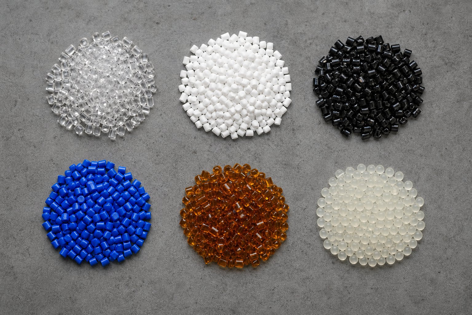
Resin-by-Resin Pelletizing Guide for Common Plastics
Two resins can share the same feedstock category, pass through identical equipment, and still produce completely different results. Why? Because every polymer family brings its own melt behavior, thermal sensitivity, moisture tolerance, and crystallization pattern to the extruder — and the operator who ignores those differences ends up chasing defects that were baked in from the moment the wrong temperature profile was loaded.
This section gives you a resin-by-resin breakdown you can reference on the production floor. For each material, you'll find the preferred method to pelletize it, the melt temperature window that keeps you out of trouble, and the specific pitfalls that cause scrap when overlooked.
Pelletizing Polyolefins and Styrenics
LDPE sits at the tricky end of the polyolefin spectrum. Its low melt strength and high tackiness mean strands love to stick together in the water bath, and the pellet plastic coming off the cutter can agglomerate before it's fully cooled. Water ring pelletizing is a natural fit here because cutting at the die face avoids the strand-handling headaches entirely — but if you're running a strand system, keeping the water bath temperature between 40 and 50 degrees C is critical to prevent surface fusion without shocking the pellet into brittleness. Typical melt temperatures run 180 to 240 degrees C. The biggest pitfall? Die-face tearing caused by inadequate melt pressure at low-viscosity conditions.
HDPE is more forgiving in terms of melt strength but demands faster cooling. Its higher crystallinity means the polymer wants to organize its chain structure during solidification, and if cooling is too slow, you get oversized crystalline structures that create internal shrinkage voids — especially in larger pellet diameters. Strand pelletizing with an adequately sized water bath works well at processing temperatures of 210 to 270 degrees C. Watch for shear overheating in the metering zone; HDPE's high viscosity generates substantial frictional heat that can push actual melt temperature well above your barrel setpoints.
PP has a sharp melting point — it transitions from solid to fluid over a narrow temperature band around 160 to 170 degrees C for homopolymer grades. That crisp transition makes it easy to process but unforgiving of extended residence times. PP degrades through chain scission rather than crosslinking, so every extra minute the melt sits in the barrel at 200 to 280 degrees C chips away at molecular weight. The result? Pellets that test fine for geometry but fail on melt flow index consistency because degradation has shifted the rheology. Rapid cooling after cutting is essential to prevent shrinkage voids driven by its high crystallinity.
PS is amorphous, which means no crystallization behavior to manage and a broad, forgiving processing window. You can pelletize PS with virtually any cutting method, and melt temperatures of 200 to 250 degrees C are typical. The catch is that PS pellets become brittle if quenched too aggressively — overcooling introduces residual stress that causes pellets to shatter during pneumatic conveying, generating fines that contaminate the product stream. A moderate cooling rate keeps pellets intact without sacrificing throughput.
ABS needs moderate shear for proper phase blending of its butadiene rubber component, but it's more moisture-sensitive than most operators expect. Undried ABS produces surface splay and internal voids that get mistaken for degassing problems. Pre-drying to below 0.05% moisture content before extrusion eliminates the issue. Processing temperatures typically fall between 200 and 250 degrees C, and low compression ratio screws help avoid the excessive shear that causes yellowing — a defect ABS buyers flag immediately.
Pelletizing Engineering Resins and PET
PET pelletizing is arguably the most demanding operation on this list, and the margin for error is razor-thin. PET is hygroscopic to an extreme degree — post-wash flakes commonly carry 3,000 to 6,000 ppm moisture, and that number must drop below 50 ppm (or below 30 ppm for food-contact applications) before the material enters the extruder. Anything higher triggers hydrolytic chain scission, which quietly destroys intrinsic viscosity (IV) and produces brittle, low-value pellets.
The pre-processing sequence adds layers that other resins don't require. Amorphous PET flakes soften at roughly 70 to 80 degrees C — well below the 160 to 180 degrees C drying temperatures needed to hit moisture targets. That means crystallization must happen first: holding flakes at 120 to 140 degrees C with continuous agitation for 30 to 60 minutes until the polymer chains reorganize into a crystalline structure that resists softening during high-temperature drying. Skip this step and you'll get a fused, unusable mass inside the hopper dryer.
PET melt temperatures run 265 to 285 degrees C, and exceeding 295 degrees C accelerates thermal degradation visibly as yellowing. Underwater pelletizing with in-line crystallization is the standard for bottle-grade PET because it produces uniform spherical pellets with controlled crystallinity — critical for downstream blow molding. Strand pelletizing works for fiber and sheet grades but demands tighter die temperature control to prevent strand breakage from PET's relatively low melt strength.
PA (Nylon) shares PET's moisture sensitivity but adds its own complication: yellowing at elevated temperatures. Nylon absorbs atmospheric moisture rapidly, and that moisture causes both hydrolysis and bubble formation during extrusion. Vacuum degassing is non-negotiable. Melt temperatures typically range from 240 to 290 degrees C depending on the grade (PA6 vs. PA66), and the processing window between adequate melting and thermal degradation is narrow enough that barrel zone temperatures need tight individual control. Strand pelletizing is most common, with the water bath providing rapid cooling that limits the oxidative yellowing accelerated by prolonged heat exposure.
PVC stands apart from every other resin on this list because of its thermal instability. PVC begins releasing hydrochloric acid (HCl) at temperatures not far above its processing range, and that HCl is corrosive to standard barrel linings, screw surfaces, and die components. Counter-rotating twin-screw extruders are the standard because they generate lower shear and more controlled heat buildup than co-rotating designs. Processing temperatures sit in a tight band of roughly 160 to 200 degrees C — the narrowest window of any commodity resin. Standard nitrided steel barrels fail within weeks under PVC's chemical attack; nickel-based bimetallic linings with corrosion resistance rated to HRC 58 to 60 are the minimum viable specification.
Resin Pelletizing Quick-Reference Table
Bookmark this table. It consolidates the critical parameters for every resin covered above into a single view — so the next time you're setting up a new material run, you can verify your process window against known best practices at a glance:
| Resin | Melt Temp Range (°C) | Shear Sensitivity | Moisture Sensitivity | Preferred Pelletizing Method | Crystallization Behavior | Special Considerations |
|---|---|---|---|---|---|---|
| LDPE | 180 - 240 | Low | Low | Water ring or strand | Low crystallinity, slow crystallization | High tackiness — control water bath temp carefully; die-face tearing risk at low melt pressure |
| HDPE | 210 - 270 | Low | Low | Strand or underwater | High crystallinity, fast cooling needed | Shear overheating in metering zone; shrinkage voids if cooling is too slow |
| PP | 200 - 280 | Medium | Low | Strand or underwater | High crystallinity, sharp melting point | Chain scission at extended residence times; rapid cooling prevents shrinkage voids |
| PS | 200 - 250 | Low | Low | Any method (broad compatibility) | Amorphous — no crystallization | Brittle pellets if overcooled; generates fines during conveying if stressed |
| ABS | 200 - 250 | Medium | Medium (pre-dry to <0.05%) | Strand | Amorphous — no crystallization | Yellowing from excessive shear; use low compression ratio screws |
| PET | 265 - 285 | Medium | Very High (dry to <50 ppm) | Underwater (bottle-grade); strand (fiber/sheet) | Semi-crystalline — crystallization during cooling is critical; requires pre-crystallization of flakes | Crystallize at 120-140°C before drying at 160-180°C; IV loss from hydrolysis if moisture is above spec |
| PA (Nylon) | 240 - 290 | Medium | Very High (vacuum degassing required) | Strand | Semi-crystalline — moderate crystallization rate | Yellowing at high temps; rapid moisture re-absorption post-drying; tight barrel zone control needed |
| PVC | 160 - 200 | High | Low | Strand with counter-rotating twin-screw | Amorphous — no crystallization | Releases HCl — corrosive to standard barrels; narrowest processing window of any commodity resin |
Notice a pattern? The resins that seem easiest to pelletize — polyolefins and styrenics — still carry hidden pitfalls that show up as subtle quality drift rather than dramatic failures. The engineering resins and PET, by contrast, announce their displeasure immediately through discoloration, bubbling, or strand breakage. Both categories demand that you match your process parameters precisely to the resin's behavior, not to a generic "one-size-fits-all" temperature profile.
Getting those parameters right produces pellets that look correct. But "looking correct" and actually meeting buyer specifications are two different things entirely — and the quality metrics that downstream processors measure go far deeper than visual inspection alone.
Pellet Quality Metrics That Downstream Buyers Measure
A pellet can look perfectly cylindrical, feel smooth to the touch, and pour freely from the bag — and still get rejected the moment it hits a buyer's quality lab. Why? Because downstream processors don't evaluate pellets with their eyes. They measure them against specification sheets built around numerical thresholds for rheology, density, contamination, and degradation. If you're producing plastic pellets for sale or even for internal consumption across departments, understanding exactly which metrics get tested — and why each one matters — is the difference between a product that sells and one that sits in a warehouse generating credit claims.
Key Pellet Quality Metrics and How They Are Measured
Seven metrics appear on virtually every pellet specification sheet in the industry. Some are familiar. Others are the ones that catch producers off guard during first-article inspections because nobody told them the test existed.
Melt Flow Index (MFI) — This is the single most referenced number in pelletizing. MFI measures how many grams of polymer flow through a standardized capillary die under a fixed load and temperature over 10 minutes, following ASTM D1238. It serves as a proxy for molecular weight distribution and rheological consistency. A higher MFI indicates a lower-viscosity, easier-flowing polymer; a lower MFI signals higher molecular weight and greater melt strength. Important product properties — tensile strength, impact resistance, elongation, and environmental stress-crack resistance — all correlate with MFI. Yet here's the catch: two polymers with identical MFI values will not necessarily behave the same under real processing conditions, because MFI is measured at a single shear rate and temperature. It doesn't account for long-chain branching, pressure gradients, or temperature profiles inside actual molds and dies. Still, it remains the quickest way for buyers to verify that a pellet lot matches their processing window — and even a 10% drift from the target value can cause cavity-fill issues in injection molding or gauge variation in blown film.
Bulk Density — Measured by filling a standardized container with pellets and dividing mass by volume (ASTM D1895), bulk density determines how many kilograms fit in a gaylord, a railcar, or a hopper. It also governs gravimetric feeder calibration. Inconsistent bulk density from lot to lot means inconsistent feed rates, which propagates through the extruder as melt pressure fluctuation. Typical ranges for commodity resin pellets fall between 0.45 and 0.65 g/cm³, though this varies with pellet shape — spherical pellets from underwater systems pack more densely than cylindrical pellets from strand cutting.
Pellet Size Distribution — Uniformity isn't optional. A batch where 95% of pellets fall within 2.5 to 3.5 mm but 5% are undersized fines or oversized agglomerates creates real processing problems: fines melt faster than standard pellets, creating hot spots and degradation; oversized pellets melt slower, producing unmelt specks in the finished part. Measurement typically involves sieve analysis with standard mesh screens, and tight distributions — standard deviations below ±0.3 mm — are what serious buyers expect.
Moisture Content — Measured via Karl Fischer titration or loss-on-drying methods, moisture is the silent killer of pellet quality in hygroscopic resins. PET buyers routinely specify maximums of 50 ppm or lower for bottle-grade pellets. Nylon buyers set similarly strict limits. Even polyolefin buyers — whose resins aren't hygroscopic — may specify surface moisture caps below 0.1% to prevent steam bubbles during high-speed injection molding. Exceeding moisture limits doesn't just cause surface defects; it triggers hydrolytic chain scission in condensation polymers, permanently reducing molecular weight and mechanical performance.
Ash Content — This test (ASTM D5630) burns away all organic material and measures the inorganic residue. For filled compounds, ash content verifies that the filler loading — whether it's 20% calcium carbonate, 30% glass fiber, or 5% TiO₂ — matches the formulation target. A lot testing at 18% ash when the spec calls for 20% means either the filler feeder drifted during production or the blending step wasn't homogeneous. Buyers of unfilled resins use ash content as a contamination indicator — any measurable ash in a supposedly unfilled pellet signals foreign material.
Yellowness Index (YI) — Measured per ASTM D1925 or ASTM E313 using a spectrophotometer, YI quantifies how far a pellet's color has shifted toward yellow. That shift is a direct fingerprint of thermal degradation — the polymer chains have been broken, oxidized, or crosslinked by excessive heat exposure during extrusion. Buyers use YI as a proxy for process control quality: pellets with elevated yellowness didn't just look bad, they've lost mechanical properties. Natural or light-colored compounds face the tightest YI limits, sometimes ±2 units from the control sample.
Contamination Levels (Black Specks, Gels) — This is where rejections hit hardest. Black specks are carbonized polymer fragments — degraded material dislodged from barrel dead spots, contaminated screen packs, or burned deposits on die surfaces. Gels are crosslinked polymer particles that won't melt uniformly and show up as visible defects in films, sheets, and transparent parts. The APR's Applications Guidance for Recycled PET establishes rigorous comparative protocols: across 50 sample preforms, if the control contains zero specks, the innovation sample must contain 2 or fewer. These limits extend to sheet applications with identical gel-count thresholds — making clear that even a handful of defects per batch can disqualify a pellet supplier.
What Downstream Processors Require From Pellet Suppliers
Here's where context separates useful pellet quality data from meaningless test reports. Not every metric carries equal weight for every application. A film producer and an injection molder buying the same PE grade will prioritize completely different parameters — and a pellet producer who doesn't understand those priorities will over-invest in the wrong quality controls while ignoring the ones that actually drive purchase decisions.
Film producers are the most demanding buyers on the planet when it comes to pellet cleanliness. A single gel in a 25-micron blown film creates a visible bump that runs continuously down the roll, potentially scrapping hundreds of meters of product. Film operations specify extremely low gel counts (often fewer than 5 gels per square meter), tight MFI tolerance bands (±0.5 g/10 min is common), and minimal pellet dust that could seed surface defects. Pellet shape matters too — spherical pellets from underwater systems feed more uniformly through gravimetric blending stations, reducing melt pressure swings that cause gauge variation in the film bubble.
Injection molders prioritize consistent bulk density and pellet geometry above almost everything else. Their machines rely on predictable screw recovery times — the interval between shots when the screw rotates to build the next melt charge. Pellets with variable size or density cause inconsistent recovery, which shows up as short shots, flash, or dimensional variation in molded parts. MFI consistency is important but usually within a broader tolerance band than film requires. Color consistency and low moisture content round out the typical specification sheet.
Blow molders — particularly those producing PET bottles — need controlled crystallinity, consistent intrinsic viscosity (IV), and low acetaldehyde content. The APR's rPET-to-Bottle protocol specifies that IV loss from pellet to preform must stay within 0.025 dL/g units, and acetaldehyde content must not increase by more than 35% compared to control samples. These are tight bounds that trace directly back to how the pellet was cooled, crystallized, and dried during pelletization.
Pellet quality is ultimately defined by the downstream processor's requirements, not by the pelletizer operator's preferences — a pellet that passes every internal test but fails the buyer's specification sheet is still a rejected pellet.
The table below maps each critical metric to its measurement standard, typical acceptable range, practical significance, and the downstream application most sensitive to deviations:
| Quality Metric | Unit / Test Method | Typical Acceptable Range | Why It Matters | Most Sensitive Application |
|---|---|---|---|---|
| Melt Flow Index (MFI) | g/10 min (ASTM D1238) | Within ±10% of target grade value | Determines processability, fill behavior, and mechanical properties | Film extrusion (tightest tolerance: ±0.5 g/10 min) |
| Bulk Density | g/cm³ (ASTM D1895) | 0.45 - 0.65 (varies by resin and pellet shape) | Affects gravimetric feeding accuracy, shipping efficiency, hopper flow | Injection molding (uniform screw recovery depends on consistent density) |
| Pellet Size Distribution | mm (sieve analysis) | 2.0 - 5.0 mm, with ≤5% outside ±0.3 mm of target | Uniform melting behavior; prevents hot spots from fines and unmelt from oversized pellets | Film extrusion and precision injection molding |
| Moisture Content | ppm or % (Karl Fischer / loss-on-drying) | <50 ppm (PET, PA); <0.1% (PE, PP, ABS) | Prevents hydrolysis, bubbles, splay, and IV loss in condensation polymers | PET bottle blow molding; nylon injection molding |
| Ash Content | % (ASTM D5630) | Within ±1-2% of target filler loading; near 0% for unfilled | Verifies filler loading accuracy and detects inorganic contamination | Compounded and filled material applications (automotive, electrical) |
| Yellowness Index (YI) | Index value (ASTM E313) | Within ±2 units of control for natural resins | Indicates thermal degradation — correlates with loss of mechanical properties | Transparent packaging, light-colored consumer goods |
| Contamination (Black Specks / Gels) | Count per area or per weight (visual / APR PET-S-09) | ≤2 specks per 50 parts (per APR protocol); <5 gels/m² for film | Causes visible defects, weak spots, and product rejection in transparent or thin-wall parts | Blown film; transparent sheet; PET bottle preforms |
Study this table closely and you'll notice something important: the metrics that matter most are the ones you can't eyeball on the production floor. MFI drift, moisture content, and gel counts all require lab instruments to detect — and by the time visual symptoms appear (yellowed pellets, foamed surfaces, visible specks), the quality gap has already produced hours of off-spec material. Proactive testing at defined intervals during production, not just end-of-lot verification, is what separates pellet producers who retain buyers from those who keep chasing new ones.
Knowing what to measure, though, is only half the battle. When those measurements come back out of spec, operators need to pinpoint the root cause quickly — and fix it without shutting down the line. That diagnostic skill depends on a structured troubleshooting approach that connects each defect to its most likely upstream cause and the corrective action that resolves it fastest.
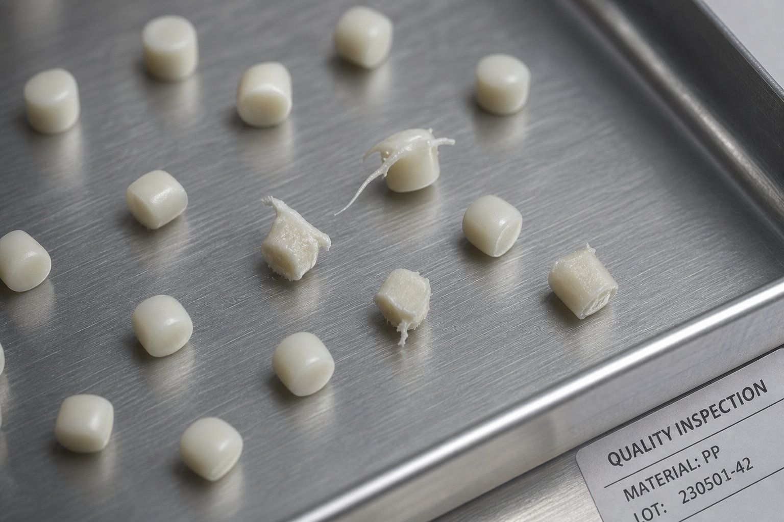
Troubleshooting Common Pelletizing Defects
Your quality lab just flagged a batch. Maybe it's tails on every third pellet. Maybe it's hollow centers that crumble under finger pressure. Maybe it's a steady creep of black specks that started subtle and now dominates the sample tray. Whatever the symptom, standing at the line staring at the pelletizer head won't fix it — but knowing exactly which upstream variable to check first will.
Every defect a plastic pelletizing machine produces traces back to a specific process imbalance. The challenge is that most defects have multiple possible causes, and adjusting the wrong variable wastes time while off-spec material keeps piling up. The approach that works on the production floor is systematic: isolate one variable, make a single change, and allow enough run time to observe the full effect before touching anything else. As Davis-Standard's pellet quality guide emphasizes, addressing one variable at a time prevents the operator from chasing compounding errors that mask the original root cause.
Below, you'll find the most common defects organized into two categories — shape and size problems versus surface and internal problems — with root causes and corrective actions mapped for each. Print this section out or bookmark it. It's built to be consulted mid-run, not read leisurely over coffee.
Pellet Shape and Size Defects
Tailing and stringing — You'll recognize this immediately: small whiskers or hair-like tails attached to the pellet edges, sometimes curling into tiny hooks. The cause is almost always a cutting problem rather than an extrusion problem. Worn blades that have lost their edge no longer shear the melt cleanly — they smear it, dragging thin filaments off each pellet as the blade passes. Insufficient cooling compounds the issue because the polymer at the cut face stays soft enough to stretch rather than fracture cleanly. On a pelletizing machine plastic operators use daily, this is one of the most frequent complaints. The fix starts with inspecting blade sharpness and replacing dull blades immediately. If blades look fine, check water temperature — raising coolant flow or lowering water temperature even a few degrees can firm up the cut face enough to eliminate tails. On die-face systems, verify that the blade contact pressure against the die plate is set correctly; spring tension or pneumatic pressure that has drifted low allows the blade to ride slightly off the surface, producing the same smearing effect.
Uneven pellet size — When pellets from the same production run vary noticeably in length or diameter, the root cause is almost always upstream of the cutter. Inconsistent strand speed — caused by a surging extruder, an unstable gear pump, or erratic feeder output — produces strands that alternate between thick and thin sections, and even a perfectly timed cutter can't compensate for material that arrives at variable diameter. Clogged die holes create the same symptom from a different direction: blocked orifices redirect melt flow through the remaining open holes, increasing strand diameter on those while neighboring holes run thin or not at all. The corrective action depends on which cause you identify. For flow instability, check the gear pump function, verify feeder calibration, and look for bridging in the hopper. For die blockage, calculate the percentage of open holes — industry guidance recommends confirming orifice status before adjusting any other pelletizer settings, since tuning the cutter to compensate for a partially blocked die only masks the real problem.
Angel hair and fines generation — Fine filaments and dust accumulating in the pellet dryer or classifier signal that the cutter isn't making clean separations. The most common cause on a plastic pelletizer machine is excessive blade-to-die gap — when the gap between the rotating knife and the die face exceeds the optimal clearance (often measured with a feeler gauge per the manufacturer's specification), the blade tears rather than cuts, generating micro-fragments with every revolution. Re-setting the cutter clearance to the specified tolerance resolves most cases. On strand pelletizers, worn nip rollers that fail to grip strands consistently can cause the strand to slip during cutting, producing short fines and dust. Replacing or re-surfacing the rollers restores grip and clean cuts. Also verify that the cutter speed matches extruder output — a cutter spinning too fast relative to strand feed rate produces excessive fines, while too slow produces elongated pellets that break during conveying.
Surface and Internal Pellet Defects
Hollow pellets and internal voids — Slice a suspect pellet in half and you'll see it: a bubble or cavity inside what should be a solid granule. This defect is one of the most damaging because it's invisible externally but compromises pellet density and mechanical integrity. The two primary causes are inadequate degassing and moisture in the feedstock. Residual water converts to steam inside the barrel, and if the vacuum vent isn't pulling those vapors out effectively, they get trapped in the melt and expand during cooling to form internal voids. Verify that the vacuum pump is achieving target pressure, check vent port seals for leaks, and confirm that exhaust lines aren't clogged with condensate or polymer buildup. On the feedstock side, test incoming material moisture with a Karl Fischer instrument — don't rely on dryer setpoints alone, because a dryer running at the right temperature with a spent desiccant bed delivers wet material that tests fine on the control panel but fails in the barrel.
Black specks — Few defects trigger buyer rejections faster. Black specks are carbonized polymer fragments — material that stagnated in a dead zone inside the barrel, screw flight, adapter, or die, degraded over hours of heat exposure, and eventually broke loose into the melt stream. Contaminated or degraded screen packs are another common source: as polymer accumulates on the upstream face of the filter mesh, it chars in place and periodically sheds carbonized flakes downstream. The corrective action is two-pronged. First, purge the barrel with a commercial purging compound designed to scour dead spots and displace degraded material. Second, replace the screen pack and inspect the breaker plate for buildup. For recurring problems, examine the screw and barrel for worn areas where material can hang up — damaged flight tips, scored barrel walls, and adapter joints with misaligned bores all create stagnation zones that generate specks continuously. On recycling lines, finer filtration mesh or adding a second filtration stage catches more contaminant particles before they reach the die.
Sticking and agglomeration — Pellets that clump together during cooling or in the collection bin are either too hot when they reach the classifier or inherently tacky due to resin characteristics. Insufficient cooling — water temperature too high, water flow rate too low, or residence time in the cooling bath too short — leaves the pellet surface soft enough to weld to neighboring pellets on contact. Lowering the process water temperature by 5 to 10 degrees C or increasing flow rate is the first adjustment to try. For inherently tacky resins like LDPE, EVA, or certain TPEs, applying a thin anti-block coating (typically a fine dusting of calcium stearate or talc) to the pellet surface immediately after cutting prevents surface-to-surface adhesion without affecting downstream processing.
Discoloration and yellowing — When pellets shift toward yellow, amber, or brown, the polymer is telling you it's been thermally abused. Excessive melt temperature, extended residence time, or both have broken polymer chains and initiated oxidation reactions. PET is particularly vulnerable — even slight overheating above 290 degrees C produces visible yellowing and measurable IV loss. The fix is straightforward but requires discipline: reduce barrel zone temperatures (especially in the metering section where shear heating peaks), increase throughput to shorten residence time, and verify that the temperature profile matches the resin manufacturer's recommendation. If discoloration persists after temperature correction, inspect the barrel for charred residue from previous runs — a thorough purge between material changes prevents cross-contamination that can mimic thermal degradation.
Quick-Reference Troubleshooting Chart
The table below consolidates every defect, cause, and corrective action into a single reference you can consult during production without hunting through paragraphs of text:
| Defect | Root Causes | Corrective Actions |
|---|---|---|
| Tailing / Stringing | Dull or worn cutting blades; insufficient cooling at cut face; low blade contact pressure on die-face systems | Replace or sharpen blades; lower water temperature or increase flow; re-set blade pressure per manufacturer spec |
| Uneven Pellet Size | Inconsistent strand speed from extruder surging or feeder instability; clogged die holes redirecting melt flow | Check gear pump and feeder calibration; clean clogged die holes; verify percentage of open orifices before adjusting cutter |
| Angel Hair / Fines | Blade-to-die gap too large; worn nip rollers (strand systems); cutter speed mismatched to output rate | Re-set cutter clearance with feeler gauge; replace or re-surface nip rollers; synchronize cutter speed to strand feed rate |
| Hollow Pellets / Voids | Inadequate vacuum degassing; moisture in feedstock converting to steam; blocked vent ports | Verify vacuum pump pressure and seal integrity; pre-dry material to spec (test with Karl Fischer); clear vent port blockages |
| Black Specks | Carbonized polymer from barrel dead spots; degraded material on screen pack; scored barrel or misaligned adapter joints | Purge barrel with purging compound; replace screen pack and inspect breaker plate; examine screw and barrel for wear-related stagnation zones |
| Sticking / Agglomeration | Insufficient cooling (high water temp, low flow, short residence); inherently tacky resin without anti-block treatment | Lower process water temperature by 5-10 degrees C; increase water flow rate; apply anti-block pellet coating (calcium stearate or talc) |
| Discoloration / Yellowing | Excessive melt temperature; extended residence time in barrel; charred residue from prior runs | Reduce barrel zone temperatures (especially metering section); increase throughput to shorten residence time; purge thoroughly between material changes |
One pattern runs through every row of that chart: most pellet defects originate upstream of the pelletizer itself. The cutter gets blamed, but the extruder, the screen changer, the dryer, and the feeder are where the root causes actually live. Effective troubleshooting means resisting the urge to adjust cutter speed first and instead tracing the symptom backward through the process chain until you find the variable that's actually out of control.
Fixing individual defects keeps the line running today. But building an operation that rarely produces defects in the first place — one where the pelletizing method, extruder configuration, wear components, and operating economics are all aligned to your specific resin and market — requires a more strategic view of the entire system.
Choosing and Optimizing Your Pelletizing Operation
Troubleshooting fixes problems one defect at a time. But what if the defects keep recurring because the line itself was configured around the wrong assumptions? Selecting a plastic pelletizer, an extruder type, and a cooling system without a structured decision process is how operations end up with equipment that technically works but never quite delivers the pellet quality, throughput, or cost efficiency the business case promised.
The framework below walks you through the five questions that should be answered — in sequence — before any equipment purchase order is signed or any existing line is reconfigured. Each answer narrows the field and points toward the pelletizer system and line configuration best suited to your specific situation.
Pelletizing Method Selection Decision Framework
Imagine you're standing in front of a whiteboard with your engineering team. Instead of jumping straight to equipment catalogs, start here:
- What resin family are you processing? This is the first filter because it eliminates options immediately. Processing PVC? You need a counter-rotating twin-screw extruder and a strand pelletizing setup — water ring and underwater systems aren't designed for PVC's thermal instability and corrosive off-gassing. Running hot-melt adhesives or waxes? Only hot die face or underwater pelletizing can handle materials that stay tacky at room temperature. Polyolefins open the widest range of choices; engineering resins like PA and PET narrow the field toward systems with precise moisture and temperature control.
- What is your target throughput? Capacity requirements sort the remaining options by scale. Below 300 kg/hr, strand or air-cooled die face systems deliver adequate output at the lowest capital cost. Between 300 and 1,000 kg/hr, water ring pelletizers offer a compact, moderately automated solution. Above 1,000 kg/hr — and especially above 5,000 kg/hr — underwater pelletizing becomes the only technology that scales without multiplying line complexity. Polymerization plants running up to 70,000 lb/hr have no practical alternative to UWP.
- What pellet geometry does your end market require? Film producers and blow molders typically prefer spherical pellets for their superior bulk density and uniform hopper flow — pointing toward underwater systems. Injection molders generally accept cylindrical pellets from strand cutting without issue. If you're producing masterbatch where micropellets are needed for accurate let-down ratios, underwater pelletizing is again the strongest fit. Lenticular pellets from water ring systems work for many applications but may underperform in high-speed automated conveying.
- Are you processing virgin or recycled material? Virgin compounded feedstock allows simpler filtration, standard degassing, and longer wear-component life — opening the door to lower-cost strand systems even at moderate throughputs. Post-consumer recyclate, by contrast, demands continuous screen changers, multiple vacuum vent ports, and wear-resistant barrel linings. The contamination profile of your feedstock may push you toward underwater pelletizing purely for its enclosed, automated process that minimizes operator exposure to inconsistent material.
- What is your budget tier? Strand pelletizing delivers the lowest capital cost and simplest maintenance but trades off in labor intensity and automation. Water ring systems sit in the middle — compact, moderately priced, and less labor-dependent. Underwater systems carry the highest upfront investment but offer the greatest automation, throughput ceiling, and material versatility. The right answer isn't always the cheapest system — it's the one whose total cost of ownership, including labor, downtime, scrap rates, and wear components, delivers the lowest cost per kilogram of on-spec pellets over the equipment's service life.
Walk through these five questions honestly, and you'll arrive at a short list of one or two pelletizer systems that match your resin, scale, market, feedstock, and budget. Skip any question, and you risk a plastic pellet making machine that checks boxes on paper but underperforms in practice.
Operational Cost Factors and Equipment Longevity
Selecting the right pelletizing method is a one-time decision. Managing the ongoing economics of running that line is a daily one — and it's where most operations leave money on the table without realizing it.
Energy is the largest variable cost in any pelletizing operation. The extruder motor alone can account for 50 to 70% of total line power consumption, with barrel heaters, vacuum pumps, water circulation systems, and pellet dryers consuming the remainder. Variable frequency drives (VFDs) on extruder motors reduce electricity consumption by matching motor output to actual load conditions — a straightforward upgrade that typically delivers 20 to 40% energy savings compared to fixed-speed drives. Barrel insulation jackets, closed-loop cooling water systems, and off-peak production scheduling compound those savings further.
Labor costs vary dramatically by pelletizing method. Strand systems are the most labor-intensive — threading up to 75 strands at each startup, monitoring for dropped strands during production, and manually managing changeovers. Underwater systems require fewer operators per shift thanks to PLC-controlled automation, but those operators need higher skill levels to manage water systems, die plate maintenance, and process parameter optimization. Water ring systems fall in between, offering pushbutton start-stop simplicity with moderate operator oversight.
Maintenance scheduling is where proactive operations separate from reactive ones. Predictive approaches — monitoring motor torque trends, tracking barrel pressure differentials, and measuring pellet size drift over time — catch problems before they generate scrap. Smart monitoring systems that analyze power draw patterns and vibration data can detect early signs of component fatigue, allowing maintenance during planned windows rather than emergency shutdowns.
Among all recurring costs, wear component replacement — screw barrels, die plates, and cutter blades — consistently ranks as one of the highest. A single twin-screw barrel replacement can represent tens of thousands of dollars in parts alone, plus the production hours lost during the swap. Blade replacement is more frequent but less expensive per event; die plates fall somewhere in between. The math is simple but often ignored: investing more in initial component quality extends replacement cycles, reduces cumulative downtime, and lowers the total cost per kilogram of pellets produced over the equipment's lifetime.
For operations running abrasive compounds — glass fiber reinforced formulations, mineral-filled masterbatch, or recycled streams contaminated with sand and metal fragments — barrel wear accelerates to the point where replacement intervals can shrink from years to months on standard nitrided steel. Purpose-built solutions engineered for these conditions make a measurable difference. NANHAIYA's parallel twin screw barrels, for example, are designed specifically for compounding, masterbatch production, and recycling environments where abrasive and corrosive formulations dominate. Their bimetallic barrel linings resist the accelerated wear that shortens standard barrel life, helping operations maintain melt consistency and extend replacement cycles in the applications where wear costs hit hardest.
Here are the key operational cost categories every pelletizing operation should track and benchmark:
- Energy — extruder motor, barrel heaters, vacuum systems, cooling water pumps, dryers, and conveying equipment
- Labor — operators per shift, skill level required, changeover time, and startup labor
- Wear components — screw and barrel replacement, die plate reconditioning, cutter blade changes, and screen pack consumption
- Downtime — planned maintenance windows plus unplanned shutdowns from equipment failure, die freeze-off, or strand breakage
- Raw material waste — startup scrap, transition scrap during changeovers, and off-spec pellets from process upsets
- Quality rejection rates — percentage of production that fails buyer specifications, measured as cost of rework, downgrade, or disposal
Track these six categories monthly, and patterns emerge quickly. You'll see which cost drivers are fixed (energy baseline, labor headcount) and which are controllable (wear component selection, maintenance timing, scrap reduction through process optimization). The operations that achieve the lowest per-kilogram pellet cost aren't necessarily the ones with the newest equipment — they're the ones that treat every component in the line as part of an integrated system rather than a collection of independent machines.
The most cost-effective pelletizing line is one designed as a complete system — where extruder, barrel, die, pelletizer, and cooling are matched to the specific resin and throughput requirements, because a mismatch at any single point cascades into higher costs at every other point downstream.
Plastic pelletizing looks deceptively simple from the outside — melt, cut, cool, bag. But as this guide has shown, the distance between mediocre pellets and consistently on-spec product runs through every decision point covered here: process stage discipline, cutting method selection, extruder and barrel configuration, feedstock-specific adjustments, resin-by-resin parameter control, quality metric awareness, defect root-cause analysis, and total-system economic thinking. Close the gaps at each stage, and the pellets take care of themselves.
Frequently Asked Questions About Plastic Pelletizing
1. What is plastic pelletizing and how does it work?
Plastic pelletizing is a thermomechanical process that converts raw or recycled plastic into uniform granules typically 2 to 5 mm in diameter. The material is fed into an extruder where it melts through controlled heating and mechanical shear, passes through melt filtration to remove contaminants, exits a die plate, gets cut into small pieces by rotating blades, and is cooled into solid pellets. These pellets serve as the standardized feedstock for injection molding, film extrusion, blow molding, and virtually all other plastics manufacturing processes. The full workflow includes 16 distinct stages from material preparation through conveying and packaging.
2. What are the main differences between strand pelletizing and underwater pelletizing?
Strand pelletizing pushes molten polymer through a die to form continuous strands that cool in a water bath before being cut into cylindrical pellets by a rotary cutter. It offers the lowest capital cost and easiest changeovers but requires more manual labor for strand threading. Underwater pelletizing (UWP) cuts the melt directly at the die face while a pressurized water stream carries away near-perfect spherical pellets. UWP handles throughputs up to approximately 70,000 lb/hr versus 44,000 lb/hr for strand systems and processes the widest range of materials, including sticky compounds. However, UWP carries higher capital and maintenance costs and risks die freeze-off if melt pressure drops.
3. Why do plastic pellets need to be dried before processing?
Hygroscopic resins like PET and nylon absorb atmospheric moisture that converts to steam inside the extruder barrel during melting. This trapped steam causes hydrolytic chain scission, which permanently breaks polymer chains and reduces molecular weight, mechanical strength, and intrinsic viscosity. Visible symptoms include internal voids, surface bubbles, splay marks, and discoloration in the finished pellets. PET requires drying below 50 ppm moisture, and amorphous PET flakes must first be crystallized at 120 to 140 degrees C before high-temperature drying can begin. Even non-hygroscopic polymers like polyethylene benefit from surface moisture removal to stabilize melt pressure and prevent die drool.
4. How do you troubleshoot black specks in plastic pellets?
Black specks are carbonized polymer fragments that originate from material stagnating in dead zones inside the barrel, screw flights, adapters, or die components, where prolonged heat exposure degrades the polymer. Contaminated or overloaded screen packs are another frequent source. To resolve the issue, purge the barrel thoroughly with a commercial purging compound, replace the screen pack and inspect the breaker plate for charred buildup, and examine the screw and barrel interior for scored surfaces or misaligned joints that create stagnation zones. For recycling lines, adding finer filtration mesh or a second filtration stage catches more contaminant particles before they reach the die and end up embedded in pellets.
5. How do you choose the right extruder for a plastic pelletizing line?
The choice depends on process complexity and resin type. Single-screw extruders suit simple re-pelletizing of pre-compounded material where intensive mixing is unnecessary. Co-rotating twin-screw extruders are essential for compounding, masterbatch production, and recycling where dispersive mixing, additive incorporation, and aggressive degassing are required. Counter-rotating twin-screw extruders handle shear-sensitive materials like PVC that degrade under high shear. Key selection criteria include mixing intensity, residence time control, throughput targets, and material sensitivity. For abrasive or corrosive formulations, selecting wear-resistant barrel solutions — such as NANHAIYA's parallel twin screw barrels at nhyscrew.com — significantly extends maintenance intervals and maintains melt consistency.
Written by
Nanhaiya Technical Team
Zhoushan Nanhaiya Plastic Machinery Co., Ltd.
The Nanhaiya technical team supports screw and barrel manufacturing projects through application review, technical communication, custom manufacturing coordination, and production and quality control.
Discuss Your Application
Related Articles
More insights on screw barrel technology and plastics processing.

What Nobody Tells You About Screw Barrel For Plastic Machine Design
Oct 10, 2026
Learn how screw barrel for plastic machine design affects melt quality, throughput, and wear life. Covers geometry, resin matching, troubleshooting, and sourcing.
Read Article
Single Screw Extruder for Sheet: Stop Guessing, Start Specifying
Oct 9, 2026
Learn how to specify a single screw extruder for sheet production. Covers screw geometry, resin-specific processing, troubleshooting, and maintenance best practices.
Read Article
PE Pipe Extruder Machine: What Datasheets Won't Tell You
Oct 9, 2026
Learn how a PE pipe extruder machine works, key specs explained, material grade selection, maintenance tips, and buyer guidance beyond the datasheet.
Read ArticleLooking for something else?
Search by material, symptom or product and jump straight to the relevant page.
These are navigation suggestions based on keyword matching — not a quotation, not a delivery commitment, and not a substitute for engineering review. Final specification is confirmed by our engineers against your drawings and processed material.
Need help with screw barrel selection?
Share your machine model, processed material and application. Our team can help with pricing and technical support.