

What Plastic Machinery Parts Are and Why They Matter
Imagine this: a single worn check ring shuts down your injection molding line at 2 a.m. on a Friday. By Monday morning, you're staring at scrapped material, missed shipments, and an overtime bill that erases a month of margin. The machine itself is fine. The part that failed? It cost less than a hundred dollars.
That scenario plays out in plastics plants every day, and it almost always traces back to the same gap: a lack of practical knowledge about the very components that keep production running. This article exists to close that gap -- not as another catalog listing, but as a working reference for maintenance teams, plant buyers, and machine rebuilders who need to make smarter decisions about their plastic machinery parts.
What Exactly Are Plastic Machinery Parts
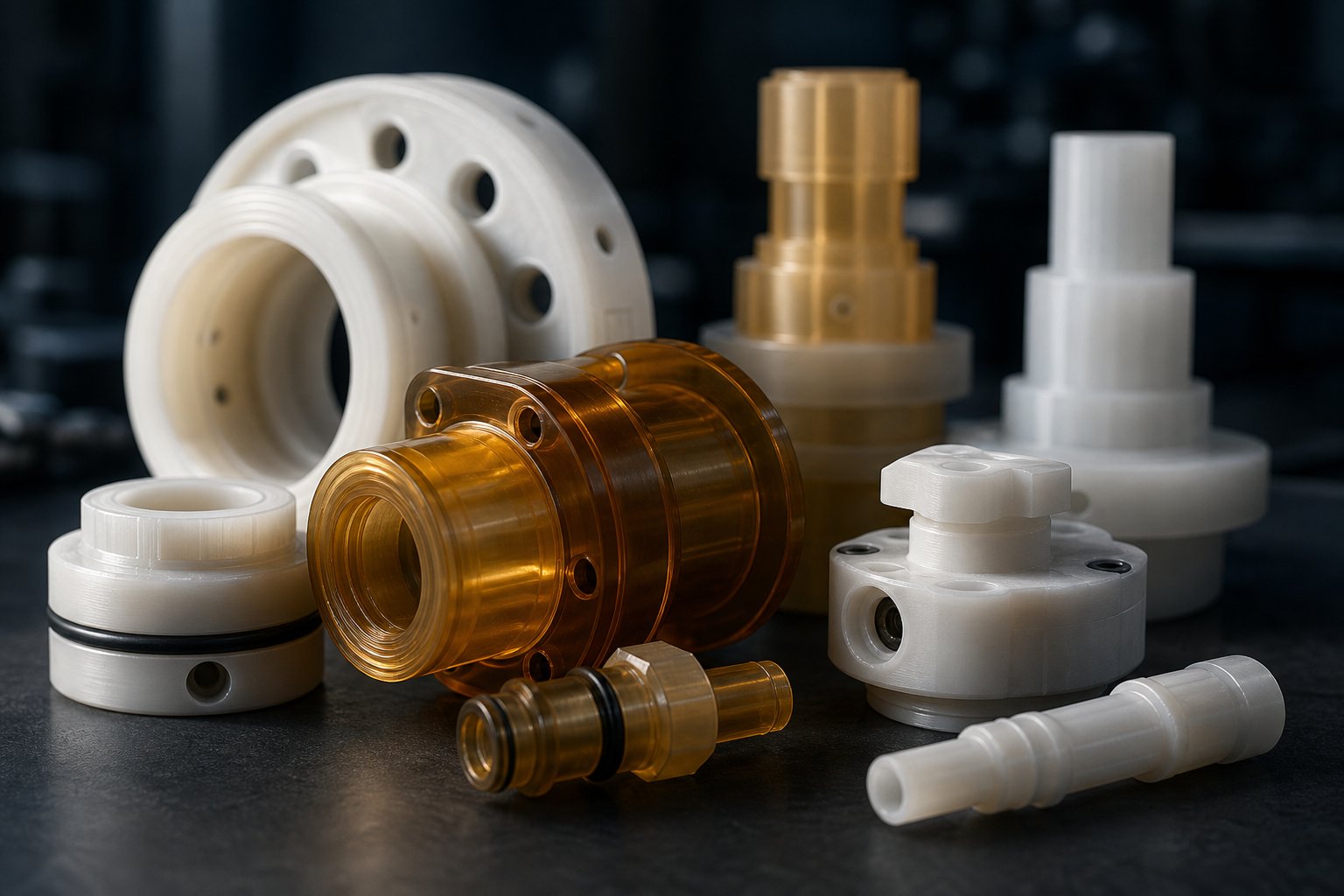
Plastic machinery parts are the consumable and wear components engineered from polymers, metals, and composites that perform critical functions inside plastic processing equipment -- extruders, injection molding machines, and blow molding lines. They are distinct from the machine frame or structure itself. Think of them as the elements that directly contact resin, regulate heat, shape output, or manage flow.
Common examples include screw tips, check rings, nozzles, heater bands, thermocouples, die heads, pelletizing blades, screen packs, and filter adapters. Each one handles a specific job within the processing cycle -- melting, conveying, shaping, or temperature regulation -- and each one wears over time. When any single component drifts out of specification, the effects ripple across your entire operation.
Why Understanding These Parts Saves Plants Money
A failed part rarely stays a small problem. Production halts the moment a critical component gives out. Material sitting in a heated barrel degrades into scrap. Operators stand idle or scramble into overtime. Downstream customers receive late shipments -- or worse, defective product that slipped through during the window of instability before the failure became obvious.
Research from the PSbyM Process Industries Performance Study found that average machine uptime at process plants sits at just 67 percent of scheduled time, with a quarter of all downtime caused by major breakdowns. For the bottom third of plants, uptime drops below 50 percent. Those numbers represent enormous lost revenue -- and most of it is preventable.
A plant's uptime depends less on the machine brand and more on the quality and compatibility of its replacement parts.
The cascading cost goes beyond the obvious repair bill. As Turner Group notes, unplanned downtime in plastics processing can easily run into thousands of dollars per hour when you account for lost output, scrapped material, idle labor, expediting costs, and strained customer relationships. A single significant shutdown event can wipe out weeks of hard-won margin.
Yet most plastics process equipment content online stops at product listings and spec sheets. It rarely explains how these parts interact, why they fail, which materials perform best in specific environments, or how to build a sourcing strategy that keeps your lines running. That is exactly what the sections ahead will cover -- from component taxonomy and material science to failure-mode diagnostics and smart replacement sourcing -- so you can fix the root cause, not just the symptom.
Common Types of Parts in Extrusion and Injection Systems
Knowing that a worn part can cascade into thousands of dollars in losses is useful -- but only if you can pinpoint which part is doing what inside the machine. Most plastics processing equipment content lumps every component into a flat product list with no context. That leaves maintenance teams scrolling through catalogs guessing at fit and function. A better approach is to organize plastic machine parts by the job they perform along the processing line: feeding and conveying resin, managing heat, and shaping the final product downstream.
Feed and Conveyance Components
Everything starts at the screw. In both extrusion and injection molding, the screw is the engine that grabs raw pellets, compresses them, and drives the melt forward. As detailed analysis of extruder operation confirms, most of the energy that actually melts the polymer comes from mechanical shear generated by the screw dragging material against the barrel wall -- not from the heater bands, as many technicians assume.
The barrel provides the chamber where this happens, and its bore dimensions must remain within tight tolerances. Even a few thousandths of an inch of wear on the barrel bore allows molten polymer to leak backward past the screw flights, robbing output and destabilizing melt pressure. At the front of the screw, the screw tip and check ring work as a pair on injection machines: the check ring acts as a one-way valve, sealing the melt in front of the screw during injection. A worn or cracked check ring lets material slip backward during shot delivery, causing short shots and inconsistent part weights.
Dimensional accuracy across these plastics components directly determines melt homogeneity and shot-to-shot consistency. When flight clearances open up, you'll notice output dropping at the same RPM, melt temperature climbing above setpoints, and specific energy consumption rising -- all signs that the screw and barrel are no longer working together efficiently.
Thermal Management Parts
Heater bands, thermocouples, and cooling elements form the temperature control backbone of any processing line. Heater bands wrap around the barrel in discrete zones, each independently controlled to create a precise melt temperature profile from feed throat to nozzle or die. A predictive maintenance study on extrusion lines found that under stable operation, each zone should hold its setpoint within roughly two to three degrees Fahrenheit, with heater duty cycles running between 40 and 70 percent.
Thermocouples are the sensors that make that control possible. They measure barrel wall or melt temperature and feed the data back to the controller. Here is the detail most operators overlook: thermocouple response time matters enormously. A sluggish or drifting thermocouple feeds the controller stale data, causing it to overshoot or undershoot temperature setpoints. The result is process instability that shows up as surface defects, dimensional variation, or degraded resin -- and the root cause is a sensor that costs a few dollars to replace.
Cooling components -- barrel cooling fans, water jackets on the feed throat -- are equally critical. The feed throat, for example, is deliberately water-cooled to prevent pellets from softening and bridging before the screw can grab them. If that cooling fails, the machine starves itself of material and output surges erratically.
Downstream and Die Components
Once the melt passes the screw tip, it enters a different world of plastic equipment focused on filtration, flow conversion, and final shaping. The screen pack and breaker plate sit between the screw and the die. Screen packs filter contaminants -- charred polymer, pellet fines, the occasional metal fragment -- while the breaker plate converts the melt's rotational flow into a clean, axial stream headed for the die. Together, they also generate the back pressure that improves melting and mixing quality upstream.
Die heads route the filtered melt from a circular cross-section into whatever profile shape the product demands -- pipe, sheet, film, or custom geometry. Filter adapters provide the interface between the barrel end and the die assembly, and their seal integrity directly affects pressure stability. Pelletizing blades, used on compounding and pelletizing lines, cut the emerging strands into uniform pellets. Dull or chipped blades produce irregular pellet shapes that cause feeding problems on downstream processing machines.
The table below organizes this full taxonomy into a quick-reference format you can bookmark or print for your maintenance team.
| Part Category | Key Components | Primary Function | Typical Failure Impact |
|---|---|---|---|
| Feed and Conveyance | Screws, barrels, screw tips, check rings | Melt, mix, and convey resin from hopper to die or nozzle | Reduced output, inconsistent shot weight, melt pressure instability |
| Thermal Management | Heater bands, thermocouples, cooling fans, water jackets | Regulate barrel and die temperature zones for process stability | Temperature overshoot or undershoot, surface defects, resin degradation |
| Filtration and Flow | Screen packs, breaker plates, filter adapters | Remove contaminants, convert rotational flow to axial, build back pressure | Contaminated product, pressure spikes, poor melt homogeneity |
| Die and Shaping | Die heads, die lips, land inserts | Shape melt into final product geometry with controlled dimensions | Profile distortion, surface roughness, dimensional variation |
| Cutting and Sizing | Pelletizing blades, strand cutters | Cut extrudate into pellets or finished lengths | Irregular pellet shape, feeding issues on downstream equipment |
Each row in this table represents a functional group where wear or failure produces a distinct set of symptoms. Recognizing which category a symptom belongs to is the fastest way to narrow down the root cause -- but the material each part is made from plays an equally decisive role in how long it lasts and how well it performs under load.
Plastic vs Metal Machinery Parts and When to Choose Each
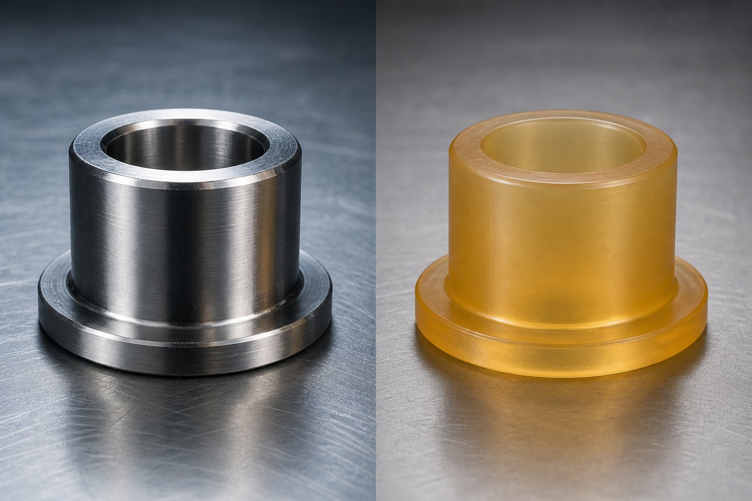
Material choice determines lifespan -- but it also determines energy draw, maintenance burden, chemical compatibility, and total cost of ownership. Yet most plant buyers default to metal replacements without ever questioning whether an engineered plastic alternative would actually outlast it in their specific application. On the flip side, swapping metal for polymer in the wrong spot can lead to premature failure that's entirely avoidable. The real answer is never "plastic is better" or "metal is better." It's "which material fits the operating conditions?"
Here's a practical, application-driven breakdown to help you decide.
Weight Reduction and Energy Savings
Engineered plastic components typically weigh 50 to 85 percent less than their metal equivalents. In a processing line full of rotating, sliding, and reciprocating parts, that weight difference compounds fast. Lighter guide rails, wear strips, bushings, and conveyor components mean less inertia for motors to overcome on every cycle -- translating directly into lower energy consumption and reduced mechanical strain on drive systems.
There's a maintenance angle, too. Many engineering plastic components are inherently self-lubricating. Materials like acetal (POM), Nylon, and PTFE-filled compounds release micro-layers of lubricant as they wear, eliminating the need for external grease systems entirely. As igus engineering data explains, self-lubricating polymer bearings are designed to operate without grease or oil, reducing contamination risk while cutting scheduled lubrication downtime to zero. In plastic manufacturing for industrial equipment, fewer grease points mean fewer chances for a maintenance step to be missed -- and fewer contamination events on the production floor.
Corrosion and Chemical Resistance Advantages
Imagine running an extrusion line processing flame-retardant compounds or PVC -- both of which release corrosive byproducts during melt processing. Metal parts in direct contact with these aggressive melt streams pit, corrode, and lose dimensional integrity over time. Engineered plastics like PEEK, PTFE, and PVDF resist the same chemicals without degradation, maintaining their surface integrity far longer than stainless steel in many acidic or caustic environments.
Food-contact applications sharpen this advantage further. Industry analysis from ChemBizR highlights that high-performance polymers fulfill FDA and EFSA compliance requirements while offering self-lubrication -- a combination that eliminates both chemical contamination risk and the lubricant contamination risk inherent in metal-on-metal assemblies. In cleaning-intensive environments with CIP (clean-in-place) and SIP (sanitize-in-place) cycles, plastics handle the constant chemical and thermal cycling without the corrosion that gradually weakens stainless steel components exposed to hot caustic solutions over thousands of wash cycles.
Noise is another overlooked benefit. Polymer-on-polymer or polymer-on-metal contact generates significantly less acoustic energy than metal-on-metal interfaces. In high-speed conveying and packaging lines, switching wear components to engineered plastic can measurably reduce shop-floor noise levels.
Where Metal Still Wins
Honesty builds trust, so let's be direct about where polymer parts fall short. Metal remains the clear choice in three scenarios:
- Extreme temperatures: Standard engineering plastics begin to soften or creep at sustained temperatures above 250 °F (121 °C). Even high-performance options like PEEK top out around 480 °F (249 °C) for continuous service. Barrel zones and nozzle tips in many injection molding processes routinely exceed these limits, making hardened tool steel or bimetallic alloys the only viable option.
- Very high mechanical loads: When a component must withstand extreme clamping forces, heavy impact, or sustained compressive loads -- think toggle pins, tie bars, or high-torque gearbox shafts -- metal's superior tensile and compressive strength is irreplaceable. Polymers under the same load will creep and deform over time, even if they handle the initial stress.
- Electrical conductivity requirements: Static dissipation in certain powder-handling or solvent-rich environments demands conductive pathways that only metal provides reliably. While carbon-filled plastics offer limited static dissipation, they cannot match the full conductivity of copper or aluminum grounding components.
The table below puts this comparison into a format you can reference quickly during your next replacement decision.
| Performance Dimension | Engineered Plastic | Metal | Advantage |
|---|---|---|---|
| Weight | 50-85% lighter than steel equivalents | Higher density increases motor load and inertia | Advantage: Plastic |
| Corrosion Resistance | Immune to most acids, bases, and solvents | Susceptible to pitting and oxidation in chemical environments | Advantage: Plastic |
| Self-Lubrication | Built-in lubricity eliminates external grease | Requires scheduled lubrication and grease systems | Advantage: Plastic |
| Noise Reduction | Dampens vibration and contact noise | Metal-on-metal contact generates high acoustic energy | Advantage: Plastic |
| Component Cost | Lower material and machining costs for most geometries | Higher material cost, especially for alloys and hardened steel | Advantage: Plastic |
| Continuous Temperature Limit | Up to ~480 °F (PEEK); most grades below 300 °F | Tool steels and nickel alloys exceed 1,000 °F | Advantage: Metal |
| Load Capacity | Lower tensile and compressive strength; susceptible to creep | Handles extreme clamping, impact, and sustained compressive loads | Advantage: Metal |
| Electrical Conductivity | Insulative; limited static dissipation with carbon fill | Fully conductive for grounding and static discharge | Advantage: Metal |
No single column in this table tells you the right answer by itself. The decision depends on the specific operating temperature, chemical exposure, load profile, and regulatory requirements at each position in your processing line. That's why material selection doesn't stop at "plastic or metal" -- it extends into which polymer or alloy, and what fillers or reinforcements shift the performance envelope in your favor.
Engineering Plastics and Fillers That Boost Part Performance
Picking polymer over metal is only the first decision. The second -- and arguably more consequential -- decision is which polymer. A guide rail machined from basic HDPE and one machined from glass-filled PEEK may look similar on the shelf, yet they'll behave like entirely different parts under heat, load, and chemical exposure. Material selection is the single most important factor in how long a replacement part lasts, and getting it wrong is the fastest route to a repeat failure. Here's a practical walkthrough of the machinable plastics you'll encounter in processing equipment, organized from commodity grades up to the high-performance tier.
Commodity and Mid-Range Polymers for Standard Applications
For positions that don't face extreme temperatures or aggressive chemicals, commodity and mid-range machinable plastic materials deliver excellent value at a fraction of the cost of premium grades. These are the workhorses you'll find in guide rails, wear strips, bushings, conveyor components, and feed-section liners across most plastics plants.
UHMW-PE (Ultra-High-Molecular-Weight Polyethylene) is often the first choice for sliding-wear applications. Its extremely low friction coefficient and outstanding abrasion resistance make it ideal for conveyor rails, chute liners, and wear pads. It handles continuous service temperatures up to roughly 180 °F (82 °C) and shrugs off most chemicals. The trade-off? It softens relatively early under heat and will creep under sustained heavy loads, so it's a poor fit near heated barrel zones.
Nylon (PA6 and PA66) steps up the load-bearing capacity. With higher tensile strength and better heat resistance than UHMW-PE -- PA66 handles continuous temperatures around 220 °F (105 °C) -- Nylon is a go-to for bushings, gears, rollers, and structural wear components. Keep in mind that Nylon absorbs moisture, which causes dimensional swelling. In humid plant environments or wash-down areas, that absorption can shift tight-tolerance parts out of spec.
Acetal (POM) offers a compelling middle ground: excellent dimensional stability, very low moisture absorption, and natural self-lubrication. It machines cleanly into precision parts like valve seats, sliding guides, and low-friction inserts. Its continuous temperature ceiling sits around 210 °F (100 °C), and it resists most solvents -- though strong acids and oxidizers will attack it.
HDPE (High-Density Polyethylene) is the budget option for non-critical wear surfaces, tanks, and low-load guides. It's easy to machine, chemically inert in most environments, and FDA-compliant in virgin grades. However, its mechanical strength and temperature resistance fall well below the other three, limiting its role in engineered plastic systems to lighter-duty positions.
High-Performance Engineering Plastics for Demanding Environments
When the application involves barrel-zone temperatures, chemically aggressive melt streams, FDA-regulated production, or continuous mechanical loads that would overwhelm commodity grades, the cost premium of a high-performance machinable plastic pays for itself in extended service life and reduced unplanned downtime.
PEEK (Polyether Ether Ketone) sits at the top of the pyramid. It handles continuous service temperatures up to approximately 480 °F (250 °C), delivers exceptional tensile strength and creep resistance, and resists a broad spectrum of industrial chemicals including hydrocarbons, steam, and many organic solvents. As engineering analysis from C.T. Stabil details, PEEK maintains its mechanical properties at elevated temperatures far better than any other machinable thermoplastic, which is why it dominates in aerospace bearings, medical sterilization components, and high-temperature processing equipment. For plastic machinery parts operating in hot zones near barrel heaters, PEEK is frequently the only polymer option that won't creep or degrade within months.
PPS (Polyphenylene Sulphide) offers an outstanding balance for applications that don't quite push into PEEK territory. It provides continuous operation up to roughly 425 °F (220 °C), excellent dimensional stability, very low moisture absorption, and inherent flame resistance. Where PPS truly shines is chemical resistance in acidic and caustic environments -- pump housings, valve components, and chemical processing fixtures often specify PPS because it handles aggressive media without the cost of PEEK. The same C.T. Stabil comparison emphasizes that the choice between PEEK and PPS should hinge on actual operating conditions, not assumptions: if your process stays below 200 °C and the primary concerns are chemical exposure and dimensional consistency, PPS delivers equivalent practical performance at a lower price point.
Torlon (PAI -- Polyamide-Imide) bridges the gap between thermoplastics and thermosets. With a continuous service temperature around 500 °F (260 °C) and the highest strength and stiffness of any injection-moldable plastic, Torlon handles severe mechanical loads at elevated temperatures -- think wear rings, thrust washers, and structural insulators in heavy-duty extruder gearboxes. Its drawback is machinability: it's harder to machine than PEEK or PPS and more sensitive to moisture during processing.
PTFE (Polytetrafluoroethylene) occupies a unique niche. Its friction coefficient is the lowest of any solid material, and its chemical inertness is virtually unmatched -- it resists nearly every industrial chemical at temperatures up to 500 °F (260 °C). However, PTFE is mechanically soft and prone to cold flow under load. That makes it ideal for seals, gaskets, slide plates, and non-stick liners, but a poor choice for structural or load-bearing roles unless it's used as a filler in another base polymer.
The Role of Fillers and Reinforcements
Base polymers rarely reach their full potential alone. Adding fillers and fiber reinforcements transforms a standard grade into an engineered plastic system tailored for a specific operating envelope. You'll encounter three primary filler categories in machinery applications, and each one shifts the performance profile in a different direction:
- Glass Fiber (GF): Increases stiffness, tensile strength, and heat deflection temperature -- often by 30 to 50 percent over the unfilled base. Glass-filled Nylon (PA66-GF30) and glass-filled PPS are among the most widely used grades for structural brackets, pump housings, and components that must resist deflection under sustained load at elevated temperatures. Ideal when the part needs to hold dimensional accuracy under both heat and mechanical stress.
- Carbon Fiber (CF): Delivers the highest strength-to-weight ratio of any common reinforcement. Carbon-filled PEEK, for example, rivals some aluminum alloys in stiffness while weighing a fraction as much. Carbon fiber also adds mild electrical conductivity, which helps with static dissipation in certain powder-handling or solvent-rich environments. Best suited for high-load rotating components, precision structural parts, and applications where weight savings directly reduce energy consumption.
- PTFE Fill: Dramatically lowers the friction coefficient and improves wear characteristics in sliding-contact applications. PTFE-filled Acetal and PTFE-filled PEEK are common choices for bearings, bushings, slide pads, and seal faces where dry-running performance is critical. The trade-off is a slight reduction in tensile strength compared to the unfilled base, so PTFE-filled grades work best in moderate-load, high-wear positions rather than heavily stressed structural roles.
Selecting the right base polymer is only half the equation. Pairing it with the correct filler turns a good material choice into a great one -- matching the part precisely to the temperature, load, friction, and chemical demands of its position in the processing line. That material decision, in turn, shapes how each part should be manufactured to preserve its engineered properties, which brings the focus to production methods and the tolerances they can deliver.
How Plastic Machinery Parts Are Manufactured
A PEEK bushing machined from bar stock on a precision CNC lathe and the same PEEK compound injection-molded in a multi-cavity tool are technically the same material -- yet they can perform very differently in service. The manufacturing process shapes internal stress patterns, surface finish, dimensional accuracy, and even the mechanical properties of the finished part. When you're evaluating replacement machined plastic parts or sourcing a new batch of wear components, understanding how each production method works -- and what trade-offs come with it -- is just as important as picking the right polymer.
Three methods dominate production of these components: CNC machining, injection molding, and additive manufacturing. Each one occupies a distinct sweet spot defined by volume, precision, complexity, and cost.
CNC Machining for Precision and Low-Volume Runs
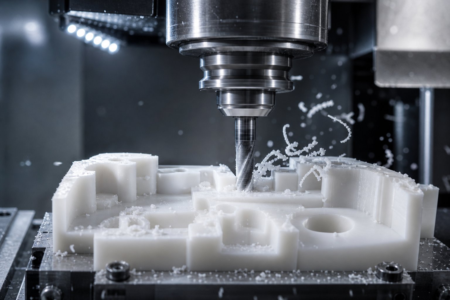
CNC machining is a subtractive process. A solid block, rod, or plate of engineering plastic is clamped into a mill or lathe, and computer-controlled cutting tools remove material along programmed tool paths until the finished geometry emerges. It's the same fundamental approach used for metal parts, but plastics introduce unique challenges that require experienced operators and carefully tuned parameters.
Why does this matter for replacement parts? Because CNC plastic parts can be produced directly from OEM drawings, reverse-engineered samples, or even measured dimensions taken off a worn component. There's no mold to build, no tooling lead time, and no minimum order quantity to justify. If your plant needs two check-ring seats machined to exact OEM spec by next week, CNC turning is how that happens.
Precision is where this method truly separates itself. Xometry's comparative data lists typical CNC machining tolerances at +/- 0.001 inches, roughly five times tighter than injection molding's typical +/- 0.005 inches. That level of accuracy is critical for machined plastic components like barrel liners, valve seats, and screw-tip assemblies where a few thousandths of an inch determine whether the part seals correctly or leaks under melt pressure.
The trade-off? Per-part cost stays relatively flat regardless of volume. Whether you machine 5 parts or 500, each one requires its own cycle time on the spindle. That makes plastic parts machining ideal for replacement components, custom one-offs, and low-to-mid-volume production runs -- but less economical when you need tens of thousands of identical pieces.
There's a subtlety worth noting: plastics behave unpredictably under cutting forces if the machinist doesn't account for material-specific quirks. As Ensinger's engineering team explains, polymers can deform under stress, absorb moisture that shifts dimensions, and generate heat that causes warping if feed rates and spindle speeds aren't tuned for the specific grade being cut. Fixturing is equally critical -- clamp a thin-walled polymer part too aggressively and you'll compress it during machining, only to watch it spring back out of tolerance once released. Experienced machinists select the right tool geometry, coolant strategy, and fixturing approach for each polymer grade, which is why the shop you choose matters as much as the material you specify.
Injection Molding for High-Volume Production
When you need thousands or hundreds of thousands of identical parts with consistent quality, injection molding becomes the economically rational choice. Molten polymer is injected under pressure into a steel or aluminum mold cavity, cooled, and ejected as a finished part. Cycle times can be remarkably short -- often under a minute per part -- and multi-cavity molds produce several pieces per cycle.
The economic math here is straightforward but often misunderstood. Mold fabrication carries significant upfront cost -- ranging from a few thousand dollars for simple single-cavity tools to several hundred thousand for complex, multi-cavity production molds. That investment only makes sense when it's amortized across a large enough production run. For a plant buyer ordering 50 replacement wear pads, commissioning a mold doesn't pencil out. For an OEM producing 50,000 identical guide blocks per year, it drives the per-part cost far below what any machining operation could match.
Tolerances in injection molding are respectable but looser than CNC work. The typical +/- 0.005-inch window works well for many functional components, but parts requiring tighter dimensional control often need secondary machining operations after molding -- adding cost and lead time. Design changes carry friction, too: modifying a molded part means modifying (or rebuilding) the tool, which introduces delays and additional expense that don't exist in CNC workflows where you simply update the program file.
Where injection molding excels beyond volume economics is material consistency. A well-controlled molding process produces parts with highly uniform density, crystallinity, and mechanical properties from shot to shot. For components where batch-to-batch consistency matters more than extreme dimensional precision, molding is hard to beat.
Additive Manufacturing and Emerging Methods
3D printing has moved well beyond the desktop-prototyping phase. Industrial additive systems using technologies like Selective Laser Sintering (SLS), Multi Jet Fusion (MJF), and high-temperature FDM are producing functional polymer parts from materials including Nylon, carbon-fiber-reinforced composites, and even PEEK. For plastic machinery parts, additive manufacturing fills a specific and growing role: bridge production and rapid prototyping of replacements when a CNC-machined or molded part isn't available fast enough.
Imagine a scenario where a custom die adapter fails and the original drawing no longer exists. Rather than waiting weeks for reverse engineering and CNC machining, a plant can 3D-scan the worn part, generate a digital model, and print a functional bridge replacement within days. It keeps the line running while a precision cnc machined plastic part is manufactured to final specification.
Current limitations are real, though, and worth understanding honestly. Tolerances on most polymer additive processes fall in the +/- 0.005 to +/- 0.010-inch range -- adequate for housings, covers, and non-critical wear components, but not tight enough for precision sealing surfaces or high-pressure melt-contact parts. Layer-by-layer construction also introduces anisotropic mechanical properties: parts are typically weaker along the build axis (the Z direction) than across it. Surface finish straight off the printer is rougher than either machined or molded surfaces, often requiring post-processing to meet functional requirements.
That said, the technology is advancing rapidly. Industry reporting on 2026 additive trends highlights that multi-laser systems, AI-driven process monitoring, and improved powder-reuse strategies have collectively reduced per-part costs by 30 to 50 percent in optimized workflows. Material libraries continue to expand into high-performance territory, and roughly 35 percent of manufacturers are already using additive methods for end-use parts -- more than double the figure from just five years ago. For complex geometries that would be prohibitively expensive to machine or impossible to mold, additive manufacturing is becoming a genuinely viable production option rather than just a prototyping convenience.
Matching the Method to the Need
Choosing the right production process is ultimately about matching your volume, precision requirements, timeline, and budget to the method that delivers the best value. The ranked list below gives you a quick framework, ordered from highest typical precision to lowest, with guidance on when each method fits best.
- CNC Machining -- Typical tolerances of +/- 0.001 inches. Best for replacement parts, low-to-mid-volume runs, and any application demanding exact dimensional match to OEM specifications. No tooling investment required; ideal when working from drawings, samples, or reverse-engineered measurements.
- Injection Molding -- Typical tolerances of +/- 0.005 inches. Most economical for high-volume production of identical parts where tooling cost is justified. Excellent batch-to-batch material consistency. Secondary machining can tighten critical dimensions where needed.
- Additive Manufacturing (3D Printing) -- Typical tolerances of +/- 0.005 to +/- 0.010 inches depending on technology. Best for prototyping, bridge production, and complex geometries that are difficult to machine or mold. Growing material range, but precision-critical and high-load applications still favor CNC machining.
A part's material determines its potential performance. The manufacturing method determines whether that potential is actually realized -- or wasted by internal stresses, loose tolerances, or surface defects that accelerate wear. Knowing how each process shapes the final product helps you ask the right questions when sourcing replacements: not just "what material?" but "how was it made, and can the supplier hold the tolerances that matter for my application?" Those questions lead directly to recognizing when a part is starting to fail -- and understanding why.
Recognizing Failure Modes and Preventing Costly Breakdowns
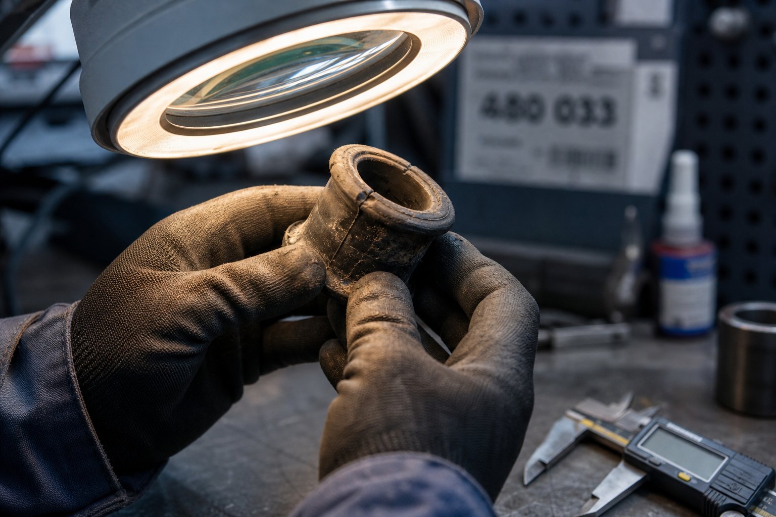
A well-chosen material manufactured to tight tolerances should deliver long, predictable service life -- in theory. In practice, plastic machined parts operate in hostile environments where heat, chemicals, cyclic stress, and abrasive fillers attack from multiple directions simultaneously. When a component fails, the instinct is to swap in an identical replacement and restart the line. But if you don't diagnose why it failed, you're just resetting a timer on the same breakdown. Understanding the specific failure mode -- and its visual fingerprints -- turns reactive maintenance into preventive action.
Common Failure Modes in Plastic Machinery Parts
Five failure mechanisms account for the vast majority of premature wear and breakdowns in polymer-based processing components. Each one leaves distinct evidence that a trained technician can spot during routine inspections -- if they know what to look for.
Creep (Slow Deformation Under Sustained Load)
Creep is arguably the most insidious failure mode because it happens gradually enough to go unnoticed until tolerances are already blown. It's the time-dependent deformation of a polymer under constant stress -- the part doesn't snap, it slowly sags, swells, or distorts. As Xometry's materials engineering team explains, creep in polymers occurs through deformation of molecular chains and viscoelastic flow, and it accelerates significantly with rising temperature. Unlike metals, which typically creep only above roughly 40 percent of their melting temperature, many polymers experience measurable creep at room temperature under sustained compressive or flexural loads.
What does it look like? Bushings that develop a visible oval shape. Guide rails that bow between mounting points. Wear pads that are noticeably thinner in the center than at the edges, even though abrasive contact is uniform. If you measure a machined plastic part and find its cross-section has changed without any surface erosion, creep is the likely culprit.
Fatigue From Cyclic Stress
Every injection cycle, every screw rotation, every reciprocating stroke subjects parts to repeated loading and unloading. Over thousands -- or millions -- of cycles, micro-cracks nucleate at stress concentration points and propagate until the part fractures. Fatigue failure is especially common in check rings, screw tips, and any component that experiences rapid pressure reversals during the injection or hold phase.
The visual indicator is subtle in early stages: fine hairline cracks radiating from corners, holes, or surface imperfections. These cracks often appear white or lighter than the surrounding material in opaque polymers -- a phenomenon called stress whitening -- because the polymer chains are separating at a molecular level before a visible fracture forms.
Chemical Degradation
Processing certain resins exposes machined plastic products to aggressive chemical attack. PVC releases hydrochloric acid during thermal processing. Flame-retardant compounds off-gas corrosive halogenated byproducts. Even cleaning agents used during purging or washdown cycles can chemically attack polymer parts if there's a compatibility mismatch.
Look for surface softening, tackiness, discoloration, or a chalky residue on parts that were originally smooth and glossy. Swelling is another telltale sign -- a part that has absorbed incompatible chemicals will measure larger than its original dimensions, and its mechanical properties will be compromised even if it still looks structurally intact.
UV Degradation in Exposed Components
Parts mounted outside of enclosed machine housings -- such as hopper liners, feed throat guides, and conveyor components near windows or bay doors -- are exposed to ultraviolet radiation that breaks down polymer chains over time. UV degradation manifests as surface yellowing, brittleness, and micro-cracking on the sun-facing side of the part. It's especially aggressive in Nylon and polypropylene-based components that lack UV stabilizer additives.
Abrasive Wear From Filled Compounds
Glass-fiber-filled resins, mineral-filled compounds, and recycled streams containing contaminants act like liquid sandpaper flowing through your processing equipment. The abrasive particles erode screw flights, barrel bores, and die land surfaces, progressively opening up clearances that degrade output quality. Research published in Plastics Technology demonstrates how even modest flight clearance increases -- from 0.005 inches to 0.016 inches per side on a 100-mm screw -- can force operators to reduce throughput by roughly 13 percent to maintain acceptable discharge temperatures, directly cutting line profitability.
The visual evidence is straightforward: polished or scored surfaces where the original machining marks have been worn away, reduced flight heights on screw elements, and barrel bores that measure oversized at inlet points where solids concentration is highest.
Wear Indicators and Inspection Practices
Spotting these failure modes early depends on knowing exactly where to look and what measurement matters most. Here are the high-value inspection points every maintenance team should build into their routine:
- Screw flight dimensions: Measure the outside diameter of screw flights at multiple points along the length. As the Plastics Technology analysis details, the flight clearance for a new screw is typically the nominal diameter divided by 1,000 -- so a 3.5-inch screw should have approximately 0.004 inches of clearance per side. Any measurement beyond twice this original clearance signals meaningful wear, and four times the original clearance is a widely used replacement threshold for general applications.
- Heater band contact surfaces: Pull heater bands during scheduled shutdowns and inspect the barrel surface beneath them. Discoloration patterns -- hot spots, localized darkening, or oxidation rings -- reveal uneven heat transfer caused by warped bands, failing heating elements, or barrel alignment issues.
- Check rings and sealing surfaces: Examine the seating surfaces of check rings for hairline cracks, pitting, and uneven wear patterns. Even microscopic cracks under cyclic injection pressure will propagate quickly, leading to back-flow that destroys shot consistency.
- Barrel bores: Use a bore gauge to measure internal diameter at several positions along the barrel length. Scoring or grooving visible on the bore surface indicates abrasive wear or metal-to-metal contact from a misaligned screw. Bimetallic barrel liners are typically about 0.060 inches thick, so bore measurements can tell you how much liner life remains.
The critical shift here is moving from calendar-based inspection schedules -- "check the screw every six months" -- to measurement-based intervals. Track dimensional data over time, plot trend lines, and let the rate of change tell you when a replacement is approaching rather than waiting for a fixed date on the calendar. A screw running unfilled HDPE at moderate speeds might hold spec for years. The same screw processing 30 percent glass-filled Nylon could need replacement in months. Only measurement reveals the difference.
Mitigation Through Material Selection and Design
Every failure mode listed above can be mitigated -- or at least significantly delayed -- by connecting the diagnosis back to smarter material and design choices. This is where the engineering plastics knowledge from earlier in this article becomes practically actionable:
Creep under sustained load? Move from standard Nylon to a glass-filled grade that raises the heat deflection temperature and resists dimensional drift. For high-temperature zones, plastic precision machined parts from PEEK or PPS outperform commodity polymers by orders of magnitude in creep resistance. As Xometry notes, adding ceramic or fiber reinforcement is one of the most effective strategies for altering a polymer's creep mechanism and increasing its resistance to deformation under sustained stress.
Chemical degradation? Swap Nylon or Acetal -- both vulnerable to strong acids -- for PPS or PTFE in positions exposed to corrosive melt byproducts or aggressive cleaning agents. UV degradation? Specify UV-stabilized grades or carbon-black-filled compounds for exposed positions, or simply shield the part from direct sunlight with a cover or housing. Abrasive wear from filled compounds? Increase the surface hardness of wear surfaces through hard-chrome plating on metal parts, or switch to carbon-fiber-filled PEEK for polymer components that need to resist particle erosion without adding weight.
The diagnostic table below pulls all of these failure modes, indicators, causes, and mitigations into a single printable reference your maintenance team can tape inside a toolbox or clip to a workstation board.
| Failure Mode | Visual Indicator | Common Cause | Recommended Mitigation |
|---|---|---|---|
| Creep (slow deformation) | Dimensional growth, oval bushings, bowed guides, uneven thickness | Sustained compressive or flexural load, especially at elevated temperatures | Upgrade to glass-filled or carbon-filled grades; select PEEK or PPS for high-heat zones; reduce sustained static loads through design changes |
| Fatigue (cyclic stress) | Hairline cracks at corners or holes, stress whitening, sudden fracture | Repeated loading/unloading cycles in injection or reciprocating systems | Increase fillet radii at stress concentrations; choose fatigue-resistant polymers; reduce cycle pressure spikes through process optimization |
| Chemical degradation | Surface softening, tackiness, swelling, chalky residue, discoloration | Incompatible resin byproducts (HCl from PVC, halogenated off-gas) or aggressive cleaning chemicals | Switch to chemically inert polymers (PPS, PTFE, PVDF); verify chemical compatibility before selecting cleaning agents |
| UV degradation | Surface yellowing, brittleness, micro-cracking on exposed face | Ultraviolet exposure on unshielded components near windows, bay doors, or outdoor installations | Specify UV-stabilized or carbon-black-filled grades; add physical shielding or covers to exposed components |
| Abrasive wear | Polished or scored surfaces, reduced flight heights, oversized barrel bores | Glass-fiber, mineral, or contaminant particles in the melt stream acting as abrasives | Use hard-faced screw flights and bimetallic barrel liners; select carbon-fiber-filled PEEK for polymer wear surfaces; increase inspection frequency for filled-resin applications |
Diagnosing a failure mode and selecting the right mitigation material is half the battle. The other half is knowing when to pull the trigger on a replacement -- and whether an OEM part, an aftermarket equivalent, or a custom-machined solution is the right call for your plant's budget, lead-time constraints, and quality requirements.
Maintenance Schedules and OEM vs Aftermarket Decisions
Spotting a failure mode early gives you a head start -- but only if your replacement strategy is ready to act on what the inspection reveals. Two decisions determine whether that head start translates into avoided downtime or just a better-documented breakdown: when you replace the part, and where it comes from.
Building a Replacement Schedule Based on Wear Data
Most plants still replace wear parts on a fixed calendar -- every six months, every annual shutdown, or whenever something breaks. The problem? Calendar-based schedules ignore the single variable that actually drives part life: operating conditions. A screw running unfilled LDPE at moderate speeds might hold tolerance for two years. That same screw processing 30 percent glass-filled PA66 at high RPMs could be out of spec in eight weeks. A six-month replacement interval would be wasteful in the first scenario and dangerously late in the second.
Condition-based replacement flips the approach. Instead of replacing parts at arbitrary intervals, you track dimensional measurements of critical wear surfaces at regular checkpoints and plot the data over time. When the trend line projects that a dimension will reach the replacement threshold within your next planned maintenance window, you schedule the swap proactively -- not reactively.
Here's what that looks like in practice: measure screw flight outside diameters every 500 operating hours, log the values, and chart the rate of change. A linear degradation curve tells you almost exactly how many hours remain before clearances exceed the threshold discussed in the previous section. The same approach works for barrel bore measurements, check ring seating surfaces, and die land dimensions. AssetWatch data from plastics plants reinforces this principle -- one facility using condition-based monitoring on a single gearbox prevented 1,200 hours of downtime and saved $1.2 million in its first year by acting on early trend signals rather than waiting for alarms or calendar dates.
The key is treating measurement data as a planning tool, not just a pass/fail check. A single measurement tells you where a part stands today. A trend line tells you when it will need attention -- and that predictive window is what separates a controlled, scheduled replacement from an emergency scramble at 2 a.m.
OEM vs Aftermarket Parts and Quality Considerations
Once you know a part needs replacing, the next question is sourcing. The choice typically boils down to OEM (Original Equipment Manufacturer) or aftermarket, and each path carries real trade-offs that deserve an honest look.
OEM parts offer guaranteed compatibility. They're manufactured to the original engineering drawings, material specifications, and tolerance stacks that the machine was designed around. As FS-Elliott's engineering team explains, design intent encompasses far more than external dimensions -- it includes proprietary material compositions, surface finish requirements, balance specifications, and validation testing that third-party manufacturers simply don't have access to. For precision-critical components still under warranty, or in applications involving high-speed rotating equipment and continuous processes, OEM parts remain the safest choice.
The downside? Lead times can stretch into weeks or months, particularly for legacy machines where the OEM has deprioritized older model support. Pricing reflects the full engineering, validation, and support infrastructure behind the brand -- which is justified, but can strain maintenance budgets when multiple components need replacement simultaneously.
Aftermarket parts -- sometimes called non-OEM or custom machined plastic parts -- enter the picture when lead time, cost, or OEM availability becomes a bottleneck. A capable plastic component manufacturer can produce replacements that match OEM specifications when working from accurate drawings, physical samples, or reverse-engineered measurements. Custom CNC plastic parts machined from the correct polymer grade, held to documented tolerances, and inspected against dimensional reports can deliver equivalent field performance at a lower price point with faster turnaround.
But quality varies enormously. The same FS-Elliott analysis highlights the "reverse engineering gap": without access to original drawings and material specs, aftermarket suppliers are essentially replicating what they can see and measure on the outside of a part. Minor deviations in geometry, material composition, or surface finish may not be visible at installation but can emerge as accelerated wear or reliability issues over time. Supplier evaluation research from Atlas Fibre reinforces this point -- the 500th part needs to match the first, and that consistency demands documented processes, disciplined inspection, and genuine material expertise rather than generic machining capability.
So how do you separate a reliable aftermarket source from a risky one? The evaluation criteria below give your procurement team a structured checklist for vetting any supplier involved in the manufacturing of engineered plastic parts.
- Material traceability: Can the supplier provide material certifications, lot numbers, and documentation confirming the exact polymer grade and filler content? A custom machined plastic parts manufacturer that can't trace its raw material back to the resin producer is a red flag.
- Tolerance verification: Does the supplier provide dimensional inspection reports -- not just a certificate of conformance, but actual measured values compared against drawing tolerances? Ask for first-article inspection data and in-process measurement records.
- Manufacturing capability from multiple input types: The best aftermarket suppliers can work from engineering drawings, physical samples, photographs, or field measurements. This flexibility matters because worn parts rarely come with original documentation attached.
- Lead time reliability: Get a realistic lead time commitment and ask about raw material inventory. A supplier that stocks common engineering plastic grades can often ship weeks faster than one that orders material only after receiving your purchase order.
- Communication responsiveness: How quickly does the supplier respond to technical questions? A supplier that engages technically during quoting -- flagging potential issues, recommending material upgrades, or questioning unnecessarily tight tolerances -- is sharing risk with you rather than leaving you to carry it alone.
- Repeat production consistency: If you'll reorder the same part periodically, ask whether the supplier maintains version-controlled CNC programs, documented setups, and inspection history. Consistency across repeat orders separates specialists from general job shops.
Neither OEM nor aftermarket is universally superior. The right choice depends on the criticality of the component, your timeline, your budget, and the quality infrastructure of the specific supplier you're evaluating. What matters most is making that choice deliberately -- armed with data, documentation, and clear evaluation criteria -- rather than defaulting to whichever option shows up first in a search result. That deliberate approach extends naturally into how you structure your entire sourcing workflow, from initial supplier qualification through ongoing inventory management.
Smart Sourcing Strategies for Replacement Parts
Having a checklist of supplier evaluation criteria is valuable -- but a checklist sitting in a drawer doesn't prevent downtime. What separates plants that consistently source quality replacement parts from those that scramble through every breakdown is a repeatable sourcing workflow: a system for finding the right plastic part supplier, qualifying them against real standards, and keeping the relationship productive over time. Engineered parts sourcing isn't a one-time event. It's an ongoing discipline that compounds in value the longer you practice it.
What to Look for in a Replacement Parts Supplier
The evaluation criteria from the previous section told you what to measure. Here's how to weight those factors when you're actively comparing plastic parts suppliers for wear components like screw tips, check rings, injection nozzles, heater bands, thermocouples, die heads, pelletizing blades, screen packs, filter adapters, and gearbox-related components.
Versatility in input formats ranks near the top. In a perfect world, every replacement order starts with a clean engineering drawing. In reality, you're often working from a worn sample pulled off the machine, a photo taken during a teardown, or a set of measurements a technician jotted down on a clipboard. The most reliable suppliers accept all of these -- drawings, samples, photos, or measured dimensions -- and have the reverse engineering capability to translate any of them into a manufacturable specification. As Specialty Manufacturing Co. explains, reverse engineering becomes essential when original drawings have been lost, the original supplier is no longer in business, or a component has been discontinued without a direct replacement. A plastic part supplier that can't work from a physical sample is a supplier that can't help you when it matters most.
Catalog breadth matters more than it appears at first glance. If you're sourcing screw tips from one vendor, heater bands from another, and die heads from a third, you're multiplying procurement complexity and tripling your qualification workload. A supplier whose catalog covers the full range of engineered parts across feed, thermal, filtration, and downstream categories lets you consolidate -- reducing purchase orders, incoming inspection events, and the number of vendor relationships your team has to manage.
Quality assurance documentation is non-negotiable. Supplier qualification research shows that companies allocating over 95 percent of procurement spend to qualified suppliers report zero major compliance observations during regulatory inspections, while qualified partners consistently achieve on-time-in-full delivery rates of at least 95 percent compared to just 82 percent for unqualified ones. At minimum, expect material certifications traceable to the resin producer, dimensional inspection reports with actual measured values, and documented change-control procedures that ensure your reorder six months from now matches the part you approved today.
Responsiveness to custom specifications separates a true engineered parts partner from a commodity vendor. You want a supplier that asks technical questions during quoting -- flagging design risks, recommending material upgrades, or pushing back on tolerances that don't serve a functional purpose. That kind of engagement signals a team that understands custom engineered products at a material and application level, not just a machining level.
One supplier worth evaluating against these criteria is NANHAIYA, which manufactures extruder spare parts -- including screw tips, check rings, nozzles, heater bands, thermocouples, die heads, pelletizing blades, screen packs, filter adapters, and gearbox components -- directly from customer-provided drawings, samples, photos, or measured dimensions. Their model is built around the exact sourcing workflow described here, making them a practical option for maintenance teams and plant buyers who need replacement parts matched to existing equipment without requiring original OEM documentation.
Streamlining Your Parts Sourcing Process
Even the best supplier relationship falls apart if your internal process doesn't support it. A few low-cost habits dramatically reduce procurement friction and shorten the path from "part failed" to "replacement installed."
Maintain a parts inventory log with OEM part numbers and dimensional specs. Every critical wear component in your processing line should have an entry that includes the part number (OEM or internal), material grade, key dimensions, source supplier, and last replacement date. When something fails at 3 a.m., a technician with access to this log can send a supplier everything needed to quote and manufacture a replacement in a single email -- instead of launching a multi-day detective hunt for a drawing that may not exist.
Photograph worn parts before disposal. This sounds trivially simple, but it rescues countless future sourcing events. A set of clear photos showing the part's geometry, mounting orientation, wear patterns, and any identifying markings gives a capable supplier a starting point for reverse engineering even when no drawing or dimensional record exists. Take photos from multiple angles, include a ruler or caliper in the frame for scale, and store them alongside the inventory log entry.
Consolidate suppliers to reduce procurement complexity. Every additional vendor in your supply chain adds qualification effort, purchase order administration, incoming inspection overhead, and communication channels to monitor. Research from Augury's spare parts planning analysis highlights how leading manufacturers are moving toward just-in-time procurement strategies that pair condition monitoring data with streamlined supplier relationships -- reducing inventory carrying costs while ensuring parts arrive precisely when needed, not months early or days late.
The best sourcing strategy isn't finding the cheapest part -- it's building a supplier relationship where quality, lead time, and communication are predictable enough to plan around.
These habits create a feedback loop. Better documentation leads to faster quotes. Faster quotes lead to shorter lead times. Shorter lead times reduce the pressure to carry excessive safety stock. And consolidated, well-qualified plastic parts suppliers deliver more consistent quality because they understand your equipment, your materials, and your tolerance requirements from repeat experience -- not from starting cold every time you call.
Reliable sourcing keeps today's production lines running. But the landscape of available materials, manufacturing methods, and inventory strategies is shifting fast -- and plants that pay attention to where the industry is heading will hold a significant advantage over those that don't.
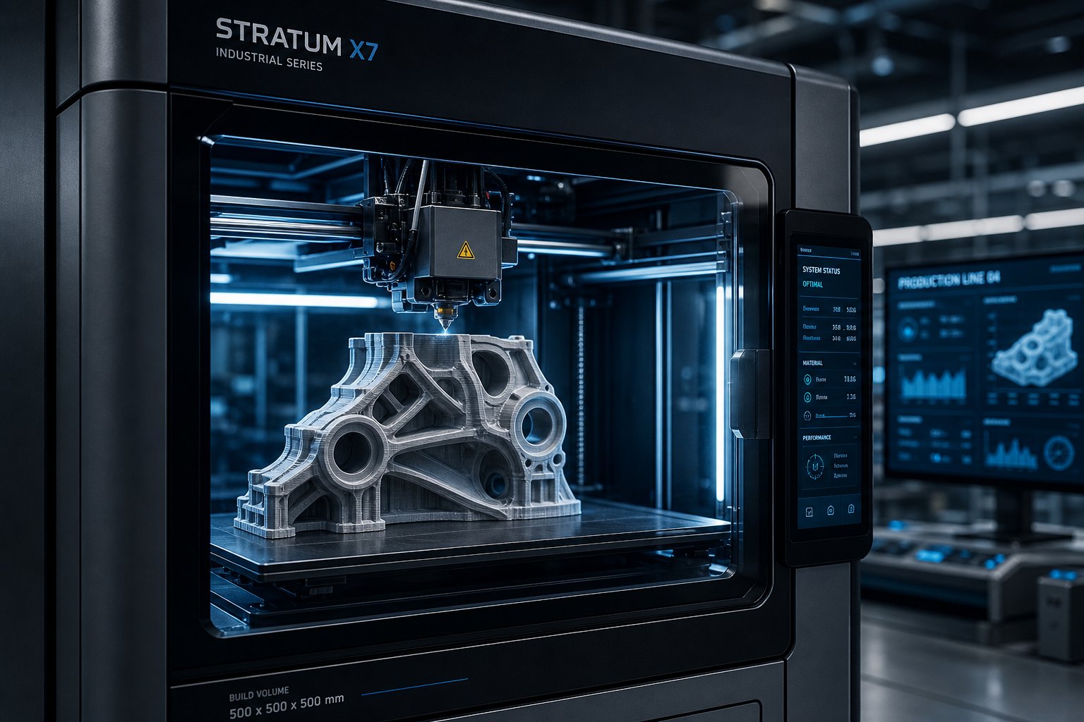
Emerging Trends Shaping the Future of Plastic Machinery Parts
Sourcing strategies built on documentation, supplier qualification, and condition-based replacement will keep your lines running today. But the tools, materials, and technologies available to maintenance teams and plant buyers are evolving rapidly -- and several shifts already underway will fundamentally change how plastics machinery components are sourced, manufactured, and monitored within the next few years. Paying attention now means you'll adopt these changes on your terms rather than scrambling to catch up after a competitor already has.
3D-Printed Replacement Parts and Digital Inventories
Imagine replacing a physical warehouse full of spare parts with a digital library of verified part files, each one printable on demand at a facility near your plant. That concept -- sometimes called a "digital inventory" -- is moving from theory into practice as additive manufacturing matures beyond prototyping into strategic production. Design News reporting on 2026 industry shifts highlights that qualified digital part files are beginning to replace physical inventory, allowing manufacturers to produce components closer to the point of use. This approach reduces transportation complexity, shortens lead times, and improves supply chain resilience -- all critical factors when a failed die adapter or worn guide block is holding up a production line.
The economics are shifting, too. Centralized, automated additive facilities -- modeled on operations like Invisalign's production of millions of unique parts daily -- demonstrate that high-mix, low-volume manufacturing can scale when paired with robotics and AI-driven process monitoring. For plastic manufacturing equipment operators, this means bridge production of non-critical spare parts can happen in days rather than weeks, keeping lines running while precision CNC machined plastic replacements are manufactured to final specification.
Honest limitations remain, though. Tolerances on most polymer additive processes still fall in the +/- 0.005 to +/- 0.010-inch range -- adequate for housings, covers, and moderate-wear components, but not tight enough for precision sealing surfaces or high-pressure melt-contact parts. Material options are expanding into PEEK and carbon-fiber-reinforced composites, yet CNC machining continues to dominate for plastic parts CNC machining applications where dimensional accuracy below +/- 0.001 inches is non-negotiable. The smart approach? Use additive for speed and flexibility on non-critical components, and reserve CNC for the precision-critical parts where tolerances govern process stability.
Bio-Based Engineering Plastics and Sustainability Pressures
Regulatory and corporate sustainability mandates are reshaping material selection well beyond consumer packaging. Industry analysis from PEZY reports that bio-based engineering plastics derived from non-food biomass -- sugar cane, cellulose, lignin -- now offer properties competitive with conventional polyamides, polycarbonates, and even PEEK. Materials like bio-PA, bio-PE, and bio-PEEK carry a 30 to 70 percent lower carbon footprint without forcing engineers to compromise on mechanical properties, heat resistance, or chemical stability.
For plants processing engineered plastic products, this trend matters on two levels. First, the EU Packaging and Packaging Waste Regulation (PPWR) taking effect in 2026 sets clear recyclability and recycled-content mandates that will ripple through supply chains, including industrial components. Second, corporate sustainability reporting requirements are pressuring procurement teams to document the environmental impact of every input -- including replacement wear parts. A maintenance buyer who can show that guide rails and bushings are sourced from bio-derived or recyclable polymer grades strengthens the plant's overall sustainability profile.
The processing side introduces new considerations. Bio-based polymers sometimes differ from fossil-based equivalents in melt behavior, shrinkage characteristics, and long-term hydrolysis resistance. Careful validation against actual operating conditions -- not just datasheet comparisons -- is essential before committing to a bio-derived grade for a demanding application. Still, the trajectory is clear: sustainable material alternatives are moving from niche experiments into mainstream industrial availability.
Advanced Composites and Smart Materials
Carbon-fiber-reinforced polymers (CFRPs) are entering plastics machinery applications that were previously metal-only territory. These advanced composites deliver stiffness and strength-to-weight ratios that rival aluminum alloys while offering the corrosion resistance and design flexibility of engineered plastics. You'll see them increasingly in structural brackets, high-speed rotating components, and weight-sensitive assemblies where reducing motor load directly cuts energy consumption.
Perhaps the most transformative development on the horizon, however, is the emergence of smart materials with embedded sensing capability. Research published in the International Journal of Innovation Studies documents how smart sensors -- including strain gauges, vibration sensors, and temperature monitors embedded directly into mechanical components -- enable real-time condition monitoring and predictive maintenance through continuous data streams analyzed by AI algorithms. Imagine a wear pad or bushing that reports its own dimensional changes to a plant dashboard, flagging replacement timing automatically rather than relying on manual measurement intervals. Early-stage implementations are combining conductive polymer compounds, MEMS sensors, and IoT connectivity to make this vision practical for industrial environments.
These technologies are still maturing. Challenges around sensor durability in high-temperature melt-contact zones, power supply for embedded electronics, and the interpretability of AI-driven diagnostics are actively being addressed. But the direction is unmistakable: the next generation of wear components won't just perform a mechanical function -- they'll communicate their own health status in real time.
Here's a summary of each trend and its direct impact on plant operations:
- 3D-printed replacement parts and digital inventories: Reduce physical warehouse footprint and enable on-demand bridge production, cutting lead times for non-critical spare components from weeks to days.
- Bio-based engineering plastics: Meet tightening regulatory and corporate sustainability mandates while maintaining mechanical performance comparable to fossil-derived polymers, strengthening supply chain ESG profiles.
- Carbon-fiber-reinforced polymer composites: Replace metal in weight-sensitive and corrosion-prone positions, lowering energy consumption and extending service intervals on high-speed rotating assemblies.
- Smart materials with embedded sensors: Transform passive wear components into active condition-monitoring devices, enabling automated replacement alerts and eliminating reliance on manual inspection schedules.
- AI-driven process optimization: Leverage real-time sensor data and digital twins to predict failures, optimize maintenance timing, and reduce scrap -- shifting maintenance strategy from reactive to truly predictive.
Every trend on this list reinforces the same three principles that have run through this entire article. Informed material selection -- choosing the right polymer, filler, and manufacturing method for each position in your processing line -- determines how long a part lasts and how well it performs. Proactive maintenance -- driven by measurement data and trend analysis rather than calendar dates or catastrophic failure -- turns unplanned breakdowns into scheduled events. And smart sourcing -- qualifying suppliers who deliver documented quality, accept flexible input formats, and communicate as technical partners -- ensures that the right replacement arrives before the production clock starts ticking against you. Plants that master these three pillars don't just fix symptoms. They eliminate root causes, and they keep their lines running while competitors are still on the phone scrambling for parts.
Frequently Asked Questions About Plastic Machinery Parts
1. What are the most common plastic machinery parts that need replacement?
The most frequently replaced plastic machinery parts include screw tips, check rings, injection nozzles, heater bands, thermocouples, die heads, pelletizing blades, screen packs, filter adapters, and barrel liners. These consumable and wear components directly contact resin, regulate heat, or shape output during processing, making them subject to continuous mechanical stress, thermal cycling, and abrasive wear. Replacement frequency depends heavily on the resin being processed -- glass-filled compounds, for example, accelerate wear dramatically compared to unfilled polymers. Suppliers like NANHAIYA manufacture these components from customer-provided drawings, samples, photos, or measured dimensions, making sourcing straightforward even when original documentation is unavailable.
2. How do I choose between plastic and metal for machinery replacement parts?
The decision hinges on specific operating conditions rather than a blanket preference. Engineered plastic parts outperform metal in applications requiring corrosion resistance, weight reduction, self-lubrication, noise dampening, and FDA compliance -- often at lower cost. However, metal remains the clear choice when continuous operating temperatures exceed roughly 480 degrees Fahrenheit, when extreme clamping or compressive loads are involved, or when full electrical conductivity is required. Evaluate each position in your processing line individually based on its temperature range, chemical exposure, mechanical load profile, and regulatory requirements before selecting the material.
3. What causes plastic machinery parts to fail prematurely?
Five primary failure modes drive most premature breakdowns: creep (slow deformation under sustained load, especially at elevated temperatures), fatigue from cyclic stress that initiates micro-cracks at stress concentration points, chemical degradation from incompatible resin byproducts or cleaning agents, UV degradation on exposed components, and abrasive wear from glass-fiber or mineral-filled compounds. Each mode leaves distinct visual indicators -- oval-shaped bushings suggest creep, stress whitening signals fatigue, surface softening points to chemical attack, and polished screw flights indicate abrasive erosion. Identifying the specific failure mode is essential for selecting the correct mitigation strategy rather than simply repeating the same replacement.
4. Should I buy OEM or aftermarket plastic machinery parts?
Neither option is universally superior. OEM parts guarantee compatibility with original engineering specifications and are the safest choice for precision-critical or warranty-covered components. However, they often carry premium pricing and extended lead times, especially for legacy equipment. Aftermarket parts from a qualified custom manufacturer can match OEM specifications when produced from accurate drawings, samples, or reverse-engineered measurements -- often at lower cost and faster delivery. The key is vetting aftermarket suppliers rigorously: verify material traceability with lot-level certifications, request dimensional inspection reports with actual measured values, confirm they can work from multiple input formats, and assess their repeat-order consistency.
5. What engineering plastics perform best in high-temperature machinery applications?
For high-temperature zones near barrel heaters or in chemically aggressive melt streams, PEEK (Polyether Ether Ketone) leads the field with continuous service capability up to approximately 480 degrees Fahrenheit and exceptional creep resistance. PPS (Polyphenylene Sulphide) offers a cost-effective alternative for temperatures up to around 425 degrees Fahrenheit, with outstanding chemical resistance and dimensional stability. Torlon (PAI) handles temperatures up to 500 degrees Fahrenheit with the highest strength of any injection-moldable plastic, making it suitable for heavy-duty wear rings and structural insulators. Adding glass-fiber or carbon-fiber reinforcement to any of these base polymers further improves heat deflection temperature and resistance to deformation under sustained mechanical loads.
Written by
Nanhaiya Technical Team
Zhoushan Nanhaiya Plastic Machinery Co., Ltd.
The Nanhaiya technical team supports screw and barrel manufacturing projects through application review, technical communication, custom manufacturing coordination, and production and quality control.
Discuss Your Application
Related Articles
More insights on screw barrel technology and plastics processing.

Extruder Machine Decoded: From Raw Pellet To Finished Product
Oct 6, 2026
Learn how an extruder machine works, compare single-screw vs. twin-screw types, and get expert guidance on specs, troubleshooting, and selection.
Read Article
PE Pipe Making Machine Decoded: From Raw Resin to Flawless Pipe
Oct 4, 2026
Learn how a PE pipe making machine works, from resin to finished pipe. Covers components, material grades, automation, troubleshooting, and buyer selection tips.
Read Article
PVC Profile Making Machine Decoded: From Raw Resin To Profit
Oct 3, 2026
Learn how a PVC profile making machine works — extrusion process steps, key technical parameters, die design, calibration methods, maintenance, and total cost of ownership.
Read ArticleLooking for something else?
Search by material, symptom or product and jump straight to the relevant page.
These are navigation suggestions based on keyword matching — not a quotation, not a delivery commitment, and not a substitute for engineering review. Final specification is confirmed by our engineers against your drawings and processed material.
Need help with screw barrel selection?
Share your machine model, processed material and application. Our team can help with pricing and technical support.