

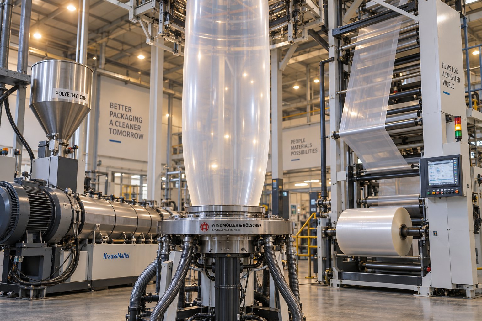
Understanding the Plastic Film Extrusion Machine
Imagine turning a handful of tiny plastic pellets into a continuous, precisely controlled sheet of film that wraps your food, protects construction materials, or shields crops from harsh weather. That transformation happens inside a plastic film extrusion machine - and it is one of the most foundational processes in modern manufacturing.
What Is a Plastic Film Extrusion Machine
At its core, a plastic extruder machine melts polymer resin and forces it through a shaped die to produce continuous thin film. The concept is straightforward, yet the engineering behind it is remarkably precise.
A plastic film extrusion machine is an industrial system that converts thermoplastic resin pellets into continuous, thin-gauge film by melting the polymer inside a heated barrel, conveying it with a rotating screw, and shaping it through a die - producing rolls of film used across packaging, agriculture, medical, and construction industries.
Two primary machine categories dominate the field. Blown film lines push molten resin through a circular die and inflate it into a bubble, creating tubular film. Cast film lines extrude the melt through a flat die onto chilled rollers, yielding flat sheet with excellent optical clarity. Each approach delivers distinct film properties - and choosing between them shapes everything from product performance to production economics.
Why Film Extrusion Matters in Modern Manufacturing
Plastic film extrusion underpins a staggering share of the global economy. The global plastic films and sheets market was valued at approximately USD 150 billion in 2025 and is projected to surpass USD 258 billion by 2034, growing at a CAGR of 6.23%. Packaging alone accounts for nearly 85% of that demand, with Asia-Pacific leading global consumption.
You'll find extruded film virtually everywhere:
- Food packaging - stretch wraps, barrier pouches, and grocery bags that preserve freshness and extend shelf life.
- Agriculture - mulch films, greenhouse covers, and silage wraps that boost crop yields.
- Medical - sterile barrier films, IV bags, and surgical drapes requiring strict quality control.
- Construction - vapor barriers, protective sheeting, and geomembranes that shield structures from moisture.
This diversity explains why plastic extrusion machines remain among the most widely deployed equipment in the polymer processing industry. A single film extrusion machine can run around the clock, converting hundreds of kilograms of resin per hour into finished rolls ready for converting or direct use.
The real question for processors and buyers, though, is not whether film extrusion matters - it is which machine type, configuration, and components best match a specific production goal. That answer starts with understanding the fundamental differences between blown and cast film processes.
Blown Film vs. Cast Film Extrusion Compared
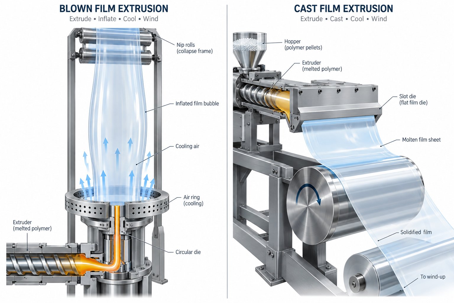
Both blown and cast processes start the same way - molten polymer forced through a die - yet the moment the melt leaves that die, each method takes a dramatically different path. That divergence determines the film's clarity, strength, thickness consistency, and ultimately which products it can serve. Understanding exactly how each process works gives you a reliable framework for matching machine type to application.
How Blown Film Extrusion Works
Picture a vertical soap bubble, except it is made of molten plastic and stands several meters tall. That image captures the essence of blown film extrusion.
In this process, molten resin exits through an annular (ring-shaped) die, forming a thin-walled tube. Compressed air is injected into the center of this tube, inflating it outward into a large, cylindrical bubble. An air ring mounted directly above the die blows a controlled stream of cooling air around the outside of the bubble, solidifying the melt at a defined height called the frost line. Once cooled, collapsing frames and nip rollers flatten the bubble into a double-layered flat film (called "lay-flat"), which is then wound onto rolls.
A central concept here is the blow-up ratio (BUR) - the ratio of the final bubble diameter to the die diameter. Adjusting the blow up ratio is one of the primary ways operators control both the film's final width and its molecular orientation. A higher BUR stretches polymer chains more aggressively in the transverse direction (across the width), boosting cross-directional strength and improving impact resistance. A lower BUR leaves more orientation in the machine direction, yielding film that is stiffer lengthwise but weaker across. Typical BUR values range from 2:1 to 4:1 for LDPE and LLDPE, while HDPE often requires 3:1 to 6:1 to achieve balanced tear and stiffness properties.
This biaxial orientation - stretching in two directions simultaneously - is what gives blown film its hallmark toughness. It is also why a blown film machine dominates applications like heavy-duty sacks, stretch wrap, and agricultural mulch films where puncture and tear resistance matter most.
How Cast Film Extrusion Works
Cast film takes an entirely different approach. Instead of an annular die and air bubble, a cast film extrusion machine uses a wide, flat slot die to extrude a thin curtain of molten polymer directly onto a high-speed, polished chill roll. The melt contacts the chilled metal surface almost instantly, quenching the polymer before crystallization can scatter light or create surface irregularities.
The result? Film with superior optical clarity, a glossy surface, and exceptionally uniform thickness from edge to edge. Because the chill roll provides rapid, even cooling across the entire web width, gauge control on cast lines is inherently tighter than on blown film systems, where bubble instability can introduce slight thickness variation.
Cast lines also run faster. Without the need to manage a tall, delicate bubble, processors can push line speeds significantly higher, making the cast process attractive for high-volume production of films where optical properties and dimensional consistency outweigh toughness demands - think retail food wrap, medical packaging, and lamination films.
The trade-off, however, is predominantly uniaxial orientation. The film stretches mainly in the machine direction as it is drawn over the chill roll, which means cast film generally offers less balanced mechanical strength compared to its blown counterpart.
Side-by-Side Process Comparison
Choosing between blown and cast methods is rarely about one being "better" - it is about which set of trade-offs aligns with your end-use requirements. The following table puts the critical differences side by side so you can evaluate them at a glance.
| Parameter | Blown Film Extrusion | Cast Film Extrusion |
|---|---|---|
| Working Principle | Annular die + air-inflated bubble; film cools as it rises vertically | Flat slot die + chill roll; film cools on contact with polished roller |
| Film Clarity | Moderate - slightly hazy due to slower cooling and crystallization | Excellent - rapid quench produces a smooth, glossy, high-clarity film |
| Mechanical Strength | Higher balanced (biaxial) tensile and puncture resistance | Good tear resistance; primarily uniaxial orientation limits cross-directional strength |
| Thickness Control | Good, but subject to bubble instability; auto-profile dies improve uniformity | Superior - chill roll provides consistent, tight-tolerance gauge across the web |
| Production Speed | Moderate - bubble management limits maximum line speed | Higher - no bubble constraints; faster winding possible |
| Capital Investment | Generally lower initial setup cost; versatile for varied product widths | Higher - precision chill rolls and flat die systems increase equipment cost |
| Typical End Uses | Grocery bags, agricultural mulch, stretch film, heavy-duty sacks, shrink film | Food wrap, medical packaging, labels, lamination films, high-clarity retail packaging |
A few practical takeaways stand out. If your priority is toughness and cost-effective versatility - especially for bags, agricultural covers, or shrink film - a blown film line is typically the stronger fit. If your products demand crystal-clear optics, tight gauge tolerance, and high throughput, a cast film extruder earns its higher price tag quickly.
Of course, the machine type is only half the equation. The components inside the extruder - barrel, screw, die head, and winding system - determine whether that machine actually delivers consistent, high-quality film shift after shift. How these parts interact as a unified system is where real production performance lives.
Key Components of a Film Extrusion Line
A plastic film extrusion machine is not a single device - it is a chain of interdependent components, each one shaping the polymer a little further on its journey from raw pellet to finished roll. When every link performs well, the line hums along producing consistent film. When even one component underperforms, the defect ripples downstream into every meter of film wound onto the roll. Understanding what each part does - and how it influences the next - is the difference between troubleshooting blind and managing a process with confidence.
Extruder Barrel, Screw, and Drive System
Think of the extruder as the beating heart of the entire line. It has one job with three phases: receive resin, melt it uniformly, and deliver a stable, pressurized flow of polymer to the die.
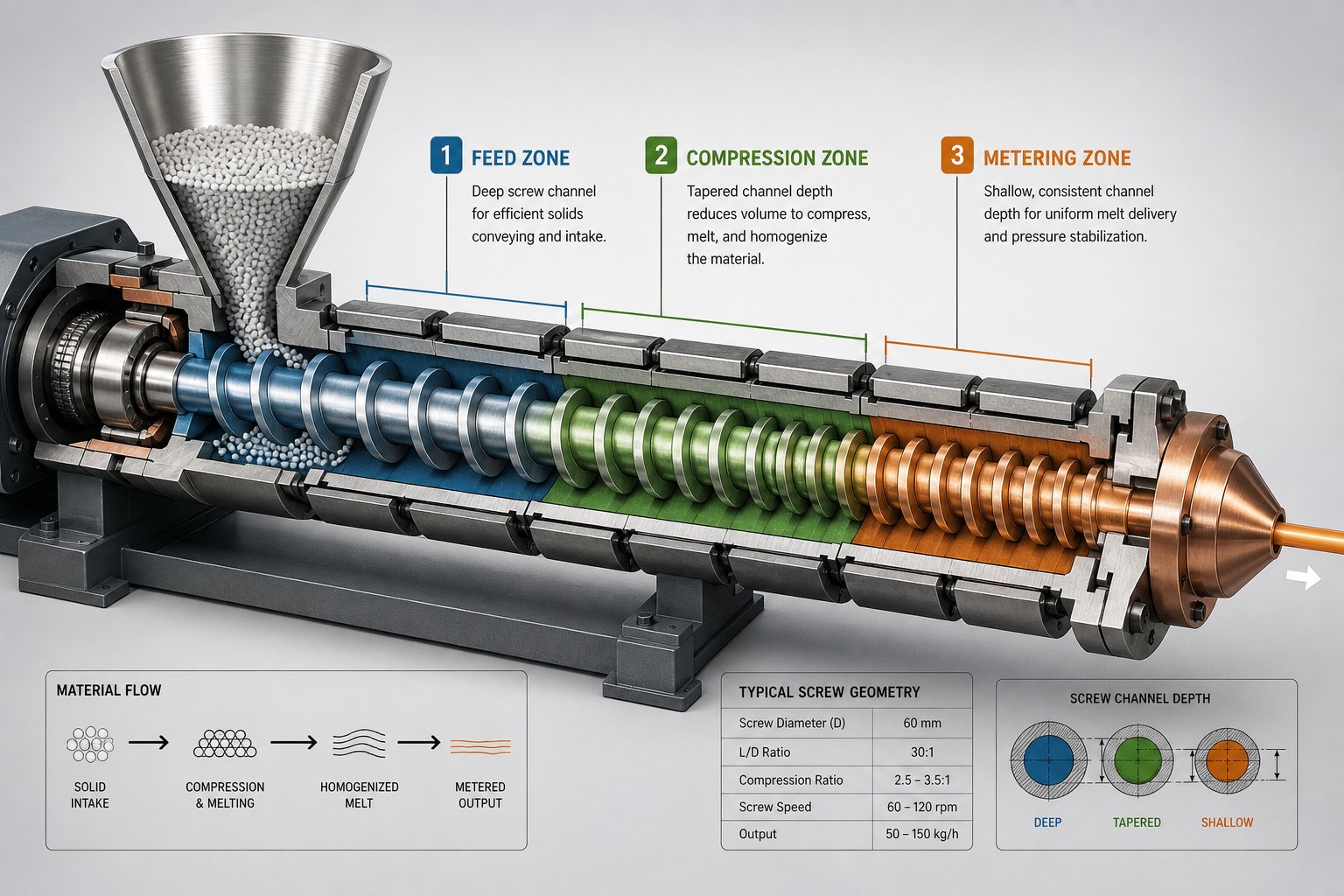
The extruder screw sits inside a heated cylindrical barrel and rotates to convey, compress, and plasticize the pellets. Its geometry is divided into three functional zones. The feed zone accepts solid pellets from the hopper and moves them forward. The compression zone applies increasing pressure as the channel depth decreases, generating shear heat that melts the resin. The metering zone homogenizes the melt and pushes it toward the die at a consistent volumetric rate.
Two specifications define an extruder's capability more than any other. Screw diameter sets the baseline throughput - larger diameters move more material per revolution. The L/D ratio (screw length divided by diameter) determines how much time the resin spends inside the extruder feed barrel. A higher L/D ratio gives the polymer more residence time for thorough melting and mixing, which is especially important when processing blends or resins that are sensitive to temperature uniformity.
Driving the screw requires serious mechanical muscle. The motor provides rotational energy, while the extruder gearbox converts high motor speed into the lower speed and higher torque the screw actually needs. A well-matched gearbox ensures smooth, vibration-free rotation - critical because even minor speed fluctuations translate directly into thickness variation in the finished film. Between the extruder and the die, a screen changer holds a fine mesh screen pack that filters contaminants and unmelted particles from the melt stream, protecting the die and improving film clarity.
Die Head, Air Ring, and Bubble Stabilization
The extrusion die is where formless molten polymer takes its first recognizable shape. On a blown film line, the annular die distributes the melt into a thin-walled tube, while on a cast line, a flat slot die spreads it into a wide curtain. In either case, uniform melt distribution across the entire die gap is essential - any uneven flow at the die shows up as gauge variation in the final product.
Die heads come in monolayer and multi-layer configurations. A monolayer die processes a single resin stream, while multi-layer co-extrusion die heads merge two, three, or more polymer streams into a single layered structure - each layer contributing distinct properties like barrier performance or sealability.
For blown film, the air ring is the primary cooling device. Mounted directly above the die, it directs a controlled curtain of air around the outside of the molten bubble. The air ring's design - single-lip, dual-lip, or automatically adjustable - directly affects cooling uniformity, which in turn controls film gauge consistency across the circumference. Complementing the air ring on higher-output lines is the IBC (Internal Bubble Cooling) system, which circulates conditioned air inside the bubble. As technical references on IBC explain, this two-sided cooling arrangement removes heat from both surfaces of the film simultaneously, enabling higher production speeds and improved bubble diameter control. A bubble stabilization cage or guide further steadies the tube above the frost line, preventing lateral sway that would create wrinkles or uneven lay-flat width.
Cast film lines replace the air ring and bubble entirely with a chill roll system - one or more highly polished, internally cooled steel rollers that quench the melt almost on contact. The rapid cooling is what gives cast film its superior optical clarity and tight gauge tolerance.
Haul-Off, Nip Rollers, and Winding System
Cooling the film is only part of the challenge. You still need to collapse, guide, and wind it into a usable roll - and this is where the downstream mechanical components take over.
On a blown film line, the collapsing frame gradually folds the round bubble into a flat lay-flat tube. At the top of the frame, a pair of nip rollers pinch the flattened tube together, sealing in the internal air pressure that keeps the bubble inflated below. These rollers also set the haul-off speed, which - together with screw speed - determines the machine-direction stretch and final film thickness. Tension control at this stage is critical: too much pull thins the film unevenly, too little causes sagging and wrinkles.
From the nip rollers, the film travels through optional treatment stations (such as corona treaters) and thickness measurement systems before reaching the winder. The winding system must build tight, uniform rolls without telescoping, wrinkling, or trapping air between layers. Poor winding quality can render otherwise perfect film unusable for downstream converting operations like printing or laminating.
Here is a consolidated view of every major component and its primary function:
- Hopper and feed throat - Receives and meters raw resin pellets into the extruder barrel.
- Extruder screw - Conveys, compresses, melts, and homogenizes the polymer.
- Extruder barrel - Provides the heated cylindrical chamber for melting; equipped with temperature-controlled zones.
- Extruder gearbox and motor - Delivers controlled torque and speed to rotate the screw consistently.
- Screen changer and breaker plate - Filters contaminants from the melt stream; builds back-pressure for uniform melting.
- Extrusion die (annular or flat) - Shapes the melt into a tube (blown) or flat web (cast).
- Air ring / IBC system - Cools and stabilizes the blown film bubble from outside and inside, respectively.
- Chill roll system - Rapidly quenches cast film on contact with polished, cooled rollers.
- Collapsing frame - Guides the blown film bubble from a round shape into a flat lay-flat configuration.
- Nip rollers - Seal bubble air pressure, set haul-off speed, and control film tension.
- Winding system - Builds finished rolls with controlled tension, alignment, and surface quality.
Every component in this chain influences the next. A perfectly designed die cannot compensate for erratic melt delivery from a worn screw, and flawless extrusion means nothing if the winder builds sloppy rolls. This systems-level perspective is exactly why processors must also consider how different extruder configurations - particularly the choice between single-screw and twin-screw designs - affect the foundation of the entire line.
Single Screw vs. Twin Screw Extruder Configurations
The extruder is the engine that drives every film line - but not all engines are built the same way. When you are specifying or replacing a plastic extruder for film production, one of the earliest and most consequential decisions is whether to use a single screw extruder or a twin screw extruder. Each configuration serves a different processing philosophy, and selecting the wrong one can mean overspending on capabilities you never use or, worse, underperforming on the materials you actually need to run.
Single Screw Extruder Advantages for Film Production
If you walk through any blown or cast film production floor worldwide, the vast majority of extruders you will see are single-screw machines. There is a reason for that dominance: for standard polyolefin resins like LDPE, LLDPE, HDPE, and PP - the workhorses of the film industry - a single screw extruder machine delivers exactly the right combination of consistent output, straightforward operation, and long-term reliability.
How does it achieve this? The single screw operates through three carefully engineered geometric zones, each performing a distinct task:
- Feed zone - The deepest channel section picks up solid pellets from the hopper and conveys them forward. Consistent feeding here prevents surging downstream.
- Compression (transition) zone - The screw channel gradually becomes shallower, compacting the pellets and generating shear heat. This is where melting begins in earnest.
- Metering zone - A shallow, constant-depth channel homogenizes the fully molten polymer and delivers it to the die at a steady, uniform pressure.
This elegant simplicity translates into real production benefits. Single-screw extruders have fewer moving parts, which means lower maintenance costs and less unplanned downtime. Their energy consumption is favorable for the steady-state melting that polyolefin film production demands. And because screw design for PE and PP processing is well established, processors can source proven geometries that deliver predictable output from day one.
Here is the practical reality most equipment guides overlook: the barrel and screw are wear components. Every kilogram of resin passing through the extrusion extruder gradually erodes the screw flights and barrel bore, especially when running filled or recycled materials. As wear progresses, the clearance between screw and barrel increases, reducing pumping efficiency and allowing melt to flow backward - a phenomenon called leakage flow. The result? Declining output rates, inconsistent melt temperature, and gauge variation in your finished film.
Proactive replacement with precision-manufactured barrels and screws is the most effective way to restore a worn line to like-new performance. Suppliers like NANHAIYA specialize in custom and replacement single screw barrels engineered specifically for film extrusion lines, along with pipe, sheet, pelletizing, and recycling applications. Their ability to match barrel metallurgy and dimensional tolerances to a specific machine and resin profile means processors can minimize downtime during replacement while regaining the output stability that tight-tolerance film production demands.
When Twin Screw Extruders Make Sense
So if single-screw machines handle the bulk of film production, why do twin screw extruders exist in film plants at all? The answer comes down to mixing intensity.
A twin screw extruder features two intermeshing screws - typically co-rotating - that create a self-wiping action and generate significantly higher shear forces than a single screw can achieve. This makes them the preferred choice in scenarios where simple melting and conveying are not enough:
- Masterbatch compounding - Dispersing concentrated color or additive masterbatch into a film resin at tight uniformity tolerances often requires the distributive mixing only intermeshing screws can deliver.
- Filled or reinforced films - When calcium carbonate, talc, or other mineral fillers need to be uniformly blended into a film formulation, the twin screw's kneading blocks break up agglomerates far more effectively.
- Hygroscopic and specialty resins - Materials like nylon (PA) or EVOH absorb moisture that must be vented during processing. Twin screw extruders incorporate vacuum venting zones that remove volatiles mid-barrel - a capability single-screw designs cannot easily replicate.
- Reactive extrusion - Producing specialty barrier or tie-layer resins sometimes involves in-situ grafting or crosslinking reactions that depend on precise residence time control and intensive mixing.
The trade-off? Twin screw extruders cost more to purchase, maintain, and operate. Their segmented barrel and modular screw element design gives tremendous flexibility, but it also increases mechanical complexity, spare parts inventory, and the expertise required to optimize screw configurations. For a standard polyethylene or polypropylene film line running a single resin, that complexity adds cost without adding value.
The table below puts these differences into practical perspective so you can match the right extruder configuration to your production reality:
| Parameter | Single Screw Extruder | Twin Screw Extruder |
|---|---|---|
| Relative Cost | Lower purchase price and operating cost | Higher capital investment; more expensive spare parts |
| Maintenance Complexity | Simple - fewer wear parts, straightforward screw removal | Complex - segmented barrels, modular screw elements, tighter tolerances |
| Throughput for Film | Excellent for standard resins; output scales predictably with screw diameter | Comparable throughput, but higher energy input per kilogram for simple resins |
| Mixing Capability | Adequate for pre-compounded resins and simple blends | Superior - high shear kneading blocks achieve thorough distributive and dispersive mixing |
| Venting / Devolatilization | Limited; requires specialized vented barrel designs | Excellent - multiple venting and vacuum zones remove moisture and volatiles efficiently |
| Best-Fit Film Applications | PE, PP, and standard polyolefin blown and cast films; the industry-standard choice for most film lines | Filled films, specialty barrier layers, masterbatch-intensive formulations, reactive or compounding-integrated film lines |
For the vast majority of film processors, the single screw extruder remains the clear default. It handles the resins that dominate film markets, costs less to own and operate, and delivers the steady-state melt consistency that tight-gauge film demands. Twin screw extruders earn their place in the lineup when the application calls for intensive mixing, in-line compounding, or processing of specialty polymers that a single screw simply cannot homogenize on its own.
Whichever configuration sits at the heart of your line, however, the resin you feed into it shapes nearly every processing parameter - from barrel temperature profile to screw compression ratio to die geometry. That relationship between material choice and machine setup is where film quality is truly won or lost.
Film Resins and Material Compatibility
Every decision about barrel temperatures, screw compression ratio, and die geometry traces back to one variable: the resin you are running. Two film lines can look identical on the outside yet perform completely differently simply because one processes LDPE while the other runs nylon. In polymer film extrusion, material choice is not just a procurement decision - it is a machine configuration decision that determines whether your line produces flawless film or fights you with every roll.
Common Film Resins and Their Processing Requirements
Imagine swapping the fuel in a diesel engine with gasoline. Sounds absurd, but running the wrong resin through an improperly configured extruder creates a comparable mismatch. Each polymer family brings its own melt behavior, cooling characteristics, and end-use strengths. The table below maps the most common film resins against the processing and performance parameters you will encounter on any polyethylene film extrusion line - or any line processing engineering-grade polymers.
| Resin | Typical Melt Temperature Range | Film Properties | Common Applications | Machine Considerations |
|---|---|---|---|---|
| LDPE | 160-230°C | Excellent clarity and flexibility; high elongation (400-800%); moderate tensile strength (8-25 MPa); good moisture barrier | Grocery bags, food wrap, shrink film, agricultural film, squeeze bottles | Low compression ratio screw; wide processing window; easy heat sealing; standard single screw extruder handles it well |
| LLDPE | 170-240°C | Superior puncture and tear resistance vs. LDPE; higher tensile strength (15-30 MPa); good clarity; excellent stretch properties | Stretch wrap, heavy-duty bags, agricultural mulch film, liners | Requires higher motor torque due to higher melt viscosity; benefits from barrier-flight or mixing screw designs |
| HDPE | 200-280°C | High stiffness and tensile strength; excellent moisture barrier; lower clarity (translucent); characteristic crinkle and stiffness | Retail carry bags, cereal box liners, industrial sacks, construction films | Higher blow-up ratios needed (3:1 to 6:1); requires higher-powered drive systems; narrower processing window |
| PP (Polypropylene) | 220-280°C | Good clarity (especially cast); excellent chemical resistance; higher heat tolerance than PE; lower density | Food packaging, BOPP labels, medical sterilization wrap, stationery films | Needs precise temperature control; sharper melting point; cast process often preferred for optical quality |
| PVC | 160-200°C | Good clarity and printability; self-extinguishing; controllable rigidity via plasticizer content | Cling wrap, blister packaging, shrink labels, credit card lamination | Requires corrosion-resistant barrels and screws (HCl release); a dedicated PVC extruder machine with specialized metallurgy is strongly recommended; narrow thermal stability window |
| PA (Nylon) | 230-290°C | Outstanding oxygen barrier; high tensile strength and puncture resistance; moderate clarity | Vacuum packaging for meat and cheese, cook-in bags, medical barrier films | Hygroscopic - must be dried before processing; often requires vented extruder or desiccant drying; typically used as a co-extrusion layer |
| EVOH | 200-240°C | Exceptional oxygen barrier (best among common film resins); moderate moisture sensitivity; good clarity | High-barrier food packaging, pharmaceutical blister lidding, fuel tank liners | Extremely moisture sensitive; almost always used as a thin inner layer in co-extrusion with PE tie layers; precise temperature control essential |
A few patterns emerge from this comparison. Polyolefins (LDPE, LLDPE, HDPE, PP) are the backbone of pe blown film extrusion and cast film production alike - they are forgiving to process and cover the widest range of everyday applications. Engineering resins like PA and EVOH unlock performance levels that polyolefins alone cannot reach, but they demand more from the equipment and the operator. PVC occupies a niche where its unique self-extinguishing and clarity properties justify the extra equipment precautions.
Matching Resin to Machine Configuration
Picking a resin from a property table is only the starting point. The extruded film you actually produce depends on how well your machine is tuned to that specific polymer's behavior. A screw designed for LDPE's broad melting range will struggle with HDPE's sharper melt point and higher viscosity. Similarly, running nylon through a barrel without proper drying and venting invites moisture-driven defects like bubbles, streaks, and degraded barrier performance.
Here are the core principles for matching resin to machine configuration:
- Screw compression ratio must suit the resin's bulk density and melting behavior. LDPE processes well with compression ratios around 3:1, while HDPE and PP typically need 3.5:1 to 4.5:1 for complete melting without overheating.
- Barrel temperature profiles should follow the resin's melt curve, not a generic setpoint. Gradual ramp-up works for polyolefins; PVC demands a flatter profile to avoid thermal degradation, while PA and EVOH need higher rear-zone temperatures to manage moisture-related issues.
- Die gap and lip geometry affect melt fracture risk. High-viscosity resins like LLDPE and HDPE benefit from wider die gaps and polished land surfaces to prevent sharkskin or melt fracture on the film surface.
- Corrosion resistance matters when processing PVC or halogenated polymers. Hydrochloric acid released during PVC processing attacks standard steel barrels and screws, requiring bimetallic or nickel-alloy construction.
- Drying and pre-conditioning are non-negotiable for hygroscopic resins. PA and EVOH must be dried to moisture levels below 0.05% prior to extrusion; failing to do so produces blown polyethylene film-quality expectations that the material simply cannot meet.
- Biodegradable and bio-based polymers are gaining traction but require adapted processing. Resins like PLA, PBAT, and starch-based blends often process at lower temperatures with modified screw geometries and may demand gentler shear to avoid premature degradation. As these emerging materials mature, expect machine manufacturers to offer purpose-built configurations alongside traditional polyolefin setups.
The takeaway is straightforward: no single machine configuration covers every resin equally well. Processors running multiple materials benefit from modular screw designs and flexible temperature control systems that allow quick changeovers. And for operations focused primarily on polyethylene blown film extrusion, investing in a screw and barrel optimized specifically for PE processing pays dividends in output consistency and energy efficiency every shift.
Of course, modern packaging rarely relies on a single resin layer. Combining multiple polymers into one structure - each layer contributing a targeted property - is where co-extrusion technology enters the picture, and it fundamentally changes how film lines are designed and operated.
Co-Extrusion and Multi-Layer Film Technology
A single polymer layer can only do so much. It might seal well but block almost no oxygen. It might offer outstanding barrier performance but refuse to bond to a printing ink. The moment one layer cannot satisfy every requirement, co-extrusion becomes the answer - and it is the reason modern blown film lines and cast film systems have evolved into multi-extruder production platforms.
How Co-Extrusion Film Lines Work
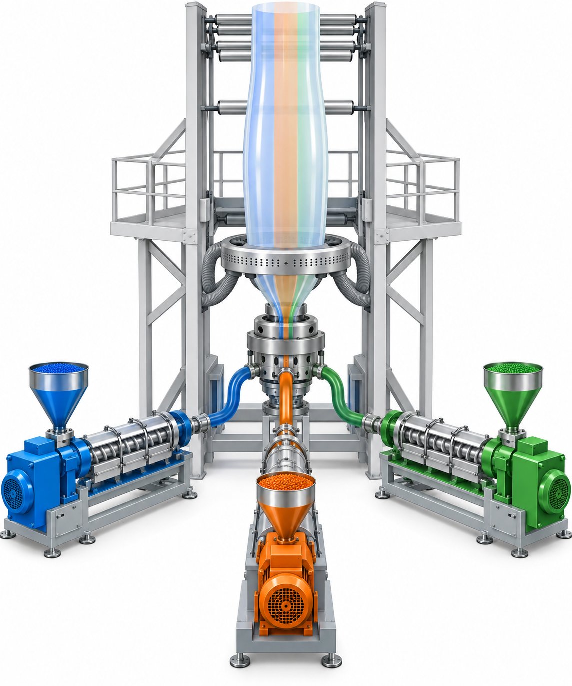
Imagine two, three, or even seven separate extruders running side by side, each one melting a different resin. Every melt stream feeds into a single co-extrusion die head, where carefully engineered flow channels merge them into one unified, multilayer structure before the film ever exits the die. The layers fuse together under heat and pressure, creating a composite film that behaves as a single sheet yet carries the distinct properties of each constituent polymer.
The simplest multi-layer configuration is the ABA structure. Here, the outer and inner layers (A) use the same resin - typically a polyethylene grade chosen for sealability and toughness - while a different material occupies the middle layer (B). Because both outer layers share a feed system, an ABA blown film line requires only two extruders, keeping equipment costs lower. This symmetric design works well for shopping bags, agricultural mulch films, and general-purpose packaging where the middle layer can incorporate recycled content or cost-reducing fillers without compromising surface quality.
Step up to an ABC configuration, and each of the three layers uses a different material, fed by three independent extruders. This unlocks significantly greater design freedom. For example, layer A might provide printability and abrasion resistance, layer B could deliver oxygen barrier performance using PA or EVOH, and layer C could be engineered for optimal heat-seal strength. ABC lines dominate high-end packaging blown film applications, medical films, and any product where each layer must serve a distinct functional role.
At the top of the complexity scale sit 5-layer and 7-layer+ blown film extrusion lines. A 5 layer blown film line adds dedicated "tie layers" - thin adhesive resin layers that bond chemically incompatible polymers together. Without tie layers, a PE outer layer and an EVOH barrier core would simply delaminate. Five-layer structures (PE / tie / EVOH / tie / PE) have become the standard architecture for high-barrier extrusion blown film, while seven- and nine-layer lines enable even finer performance tuning - thinner barrier layers, additional structural skins, or asymmetric designs tailored to specific forming or sealing demands.
Applications That Require Multi-Layer Films
Why go through the added complexity and investment? Because certain end-use demands are physically impossible to meet with a single resin layer.
Consider food packaging. A monolayer PE pouch offers decent moisture resistance and seals easily, but its oxygen transmission rate is far too high for oxygen-sensitive products like fresh meat, cheese, or coffee. Combining PE with a thin EVOH core - as in the PE/EVOH/PE structure - drops oxygen permeation by orders of magnitude, extending shelf life from days to weeks. That is the power of packaging blown film engineered at the layer level.
Pharmaceutical blown film applications push requirements even further. Blister lidding and sterile barrier pouches often need simultaneous oxygen barrier, moisture barrier, puncture resistance, and precise thermoformability - a combination that only multi-layer co-extrusion can deliver reliably at production scale.
Here are common multi-layer film structures and the applications they serve:
- PE / tie / PA / tie / PE (5-layer) - Vacuum-sealed meat, cheese, and processed foods requiring high puncture resistance and moderate oxygen barrier.
- PE / tie / EVOH / tie / PE (5-layer) - Long shelf-life packaging for coffee, snacks, and ready meals where superior oxygen barrier is critical.
- PA / EVOH / PE (3-layer ABC) - Thermoformable medical packaging and cook-in bags combining strength, barrier, and sealability.
- PE / PE / PE (3-layer ABA) - Cost-optimized bags and agricultural films using recycled content in the middle layer.
- PP / tie / EVOH / tie / PP (5-layer) - Hot-fill and retortable containers for sauces, soups, and dairy products needing heat resistance plus gas barrier.
- 7-layer+ asymmetric structures - Ultra-high-barrier films for pharmaceutical packaging, military MRE pouches, and specialty industrial applications.
The common thread across all of these structures is clear: each layer earns its place by contributing a property that no other layer in the stack provides. Designing these structures effectively, however, requires more than just understanding materials and die heads. It demands a systematic approach to matching the right machine type, resin combination, and line configuration to a specific production goal - a decision framework that separates confident buyers from those relying on guesswork.
How to Select the Right Film Extrusion Machine
You understand the processes. You know the components. You can distinguish blown from cast, single screw from twin screw, and monolayer from multi-layer. Yet here is where most buyers stall: translating all of that technical knowledge into an actual purchasing decision. Which extrusion machine fits your specific product, production volume, and budget - not in theory, but in practice?
A disciplined, process-first approach eliminates guesswork. Instead of browsing equipment catalogs and comparing spec sheets in isolation, start with what you need to produce - then work backward to the machine that delivers it.
Mapping End-Use Applications to Machine Types
Every film product carries a distinct combination of performance demands, resin requirements, and production economics. The table below connects specific end-use applications directly to the machine type, resin, and priorities that should guide your evaluation when contacting blown film extrusion machine manufacturers or film extruder suppliers.
| End-Use Application | Recommended Machine Type | Typical Resin Choices | Key Specifications to Prioritize |
|---|---|---|---|
| Food packaging (pouches, wraps) | Blown co-extrusion (3-5 layer) or cast | LLDPE, LDPE, PA, EVOH | Gauge uniformity, barrier layer control, hygienic design, co-extrusion die precision |
| Agricultural mulch film | Blown (monolayer or ABA) | LDPE, LLDPE, biodegradable blends | Wide lay-flat width, UV-stabilized resin compatibility, robust bubble cooling |
| Stretch wrap | Cast (preferred) or blown | LLDPE, metallocene LLDPE | High line speed, tight gauge tolerance, cling/release layer capability |
| Garbage bags / refuse sacks | Blown (monolayer or ABA) | HDPE, LLDPE, recycled PE | High throughput (kg/hr), ability to process recycled content, cost-effective operation |
| Medical packaging | Blown co-extrusion (5-7 layer) or cast | PE, PA, EVOH, PP | Cleanroom compatibility, precise layer distribution, validated process control |
| Construction vapor barriers | Blown (monolayer or ABA) | LDPE, HDPE, cross-laminated PE | Heavy gauge capability (100-300 micron), wide width, puncture resistance |
| Shrink film | Blown (biaxial orientation advantage) | LDPE, PVC, POF (polyolefin shrink) | Controlled blow-up ratio for balanced shrink, consistent orientation, heat tunnel compatibility |
Notice a pattern? Blown film extrusion machines dominate when toughness, wide widths, or biaxial strength are priorities - which covers the majority of commodity and industrial film applications. Cast lines earn their place where optical clarity, speed, and gauge precision matter most. And co-extrusion is not a luxury; it is a necessity whenever the finished product demands barrier performance or multi-functional layer design.
Production Volume and Scale Considerations
Your target output volume - measured in kilograms per hour - is the single most influential factor in sizing an extruder machine. Everything scales with it: screw diameter, motor power, die size, cooling capacity, and line speed. A processor targeting 80 kg/hr for a niche medical film needs a fundamentally different line than one producing 500 kg/hr of agricultural mulch.
As a general guideline, small-to-medium operations (1-5 tons per day) typically run single-extruder blown film lines with screw diameters in the 45-65 mm range. Higher-volume producers (10+ tons per day) step up to 75-120 mm screws, more powerful drives, and often multi-layer co-extrusion configurations that improve both output and product versatility. A reliable blown film machine manufacturer will help you match screw size and motor power to your specific resin and throughput target - not simply quote the largest line they sell.
Yet the extruder itself is only a fraction of the total investment. Buyers who focus exclusively on the machine purchase price often underestimate the full scope of what a production-ready installation actually costs. A buyer's analysis of total cost of ownership reveals that the best extruders for thermoplastics can actually save money over five years when energy efficiency, uptime, and maintenance are factored in.
Here are the factors that affect total cost of ownership beyond the machine purchase price:
- Installation and commissioning - Foundation, electrical hookup, compressed air supply, and startup supervision by the equipment supplier.
- Utilities infrastructure - Electrical capacity (three-phase power, adequate amperage), cooling water circuits, and compressed air systems.
- Auxiliary equipment - Resin drying systems, gravimetric blenders, material conveying, edge trim recycling units, and corona treaters are often essential but quoted separately.
- Operator training - Skilled operators directly impact film quality, scrap rates, and machine longevity. Budget for both initial training and ongoing skill development.
- Facility requirements - Ceiling height (blown film towers can reach 10+ meters), floor space, ventilation, and environmental compliance considerations.
- Energy consumption - The extruder motor and barrel heaters represent the largest ongoing operating cost. High-efficiency servo drives and optimized screw designs reduce energy use per kilogram of film produced.
- Spare parts and wear components - Screws, barrels, die lips, air ring components, and screen packs all wear over time and require periodic replacement to maintain output quality.
Key Specifications to Evaluate Before Purchasing
When you are comparing quotes from different film extruder suppliers or evaluating an extrusion machine upgrade, these are the critical specifications to examine - in order of impact on your production capability:
- Screw diameter - Determines baseline output capacity. Common film line sizes range from 40 mm (lab/pilot) to 120 mm+ (high-volume production).
- L/D ratio - Affects melt quality and mixing. Film lines typically use 28:1 to 33:1 for standard polyolefins; longer ratios suit more demanding resins or blended formulations.
- Motor power and drive type - Must match the torque and speed demands of your primary resin. Servo-driven or AC vector drives offer better energy efficiency and speed control than older DC systems.
- Output capacity (kg/hr) - Verify rated output for your specific resin, not just the manufacturer's maximum claim under ideal conditions. As process-first sizing guidance emphasizes, a line's real performance is constrained by its weakest component - often cooling capacity, not extruder throughput.
- Achievable film thickness range - Confirm the minimum and maximum gauge the line can produce with acceptable quality. Thinner films demand tighter process control and better cooling systems.
- Maximum lay-flat width (blown) or web width (cast) - Must accommodate your widest product specification with margin for edge trim.
- Line speed - Higher speeds increase output but require correspondingly capable cooling, haul-off, and winding systems to maintain film quality.
- Number of extruders (for co-extrusion) - Each additional extruder adds a layer capability but also increases floor space, power demand, and operational complexity.
- Automation and control level - Automatic gauge control, gravimetric dosing, and IBC systems add cost but reduce scrap, operator dependency, and variability.
- Supplier support infrastructure - After-sales response time, spare parts availability, and local service presence directly affect your uptime and long-term operating cost.
Resist the temptation to simply choose the blown film extrusion machine with the highest output number on the spec sheet. The line that best aligns with your actual process requirements - your resin, your film thickness, your production volume, your quality tolerance - will outperform an oversized or undersized alternative every time.
Selecting the right core equipment, however, only gets you partway to a complete production operation. The auxiliary systems surrounding the extruder - corona treaters, thickness gauges, edge trim recyclers, slitters, and the automation technologies tying them all together - determine whether that well-chosen machine reaches its full potential on the factory floor.
Downstream Equipment and Emerging Industry Trends
A perfectly tuned extruder pushing flawless melt through an optimized die still does not give you a finished product. What happens after the film leaves the nip rollers - how it is treated, measured, trimmed, and wound - shapes whether that film actually meets a converter's requirements or gets rejected at incoming inspection. Meanwhile, the extrusion equipment surrounding the core machine keeps evolving, driven by labor shortages, sustainability mandates, and the relentless push for tighter tolerances at higher speeds. Understanding the full film extrusion line - from corona treater to IoT dashboard - separates operators who simply run a machine from those who manage a production system.
Downstream Finishing Equipment
Picture this: your extruder is producing beautifully consistent film, gauge is on target, and the winder is building clean rolls. You ship those rolls to a converter - and they call back because the printing ink will not adhere. Or a customer rejects your delivery because a subtle thickness drift created a narrow band of out-of-spec material across 200 meters of film. These are not extruder problems. They are downstream problems, and solving them requires auxiliary systems purpose-built for film finishing.
Here are the critical downstream systems and what each one contributes to your finished product:
- Corona treater - Polyethylene and polypropylene films have naturally low surface energy, meaning inks, adhesives, and coatings bead up rather than bond to them. A corona treater applies a high-voltage electrical discharge across the film surface, oxidizing it and raising its surface energy (measured in dynes/cm) to levels where printing and laminating adhesion become reliable. Without this treatment step, virtually no PE or PP film can be commercially printed.
- Automatic thickness gauge (beta or infrared scanning) - Real-time, non-contact sensors continuously measure film gauge as the web moves at production speed. On blown film lines, these scanning gauges feed measurement data back to automatic die-bolt or air-ring adjustment systems that correct thickness variation on the fly. The result is tighter gauge tolerance, less material waste from over-gauging, and documented proof of conformance for quality-critical customers. As Roll-2-Roll Technologies highlights, wide-area non-contact sensing can also measure lay-flat width and detect edge-bead transitions, replacing manual measurements with automatic feedback via EtherNet/IP or PROFINET.
- Edge trim recycling system - Every blown or cast film line generates edge trim - the narrow strips cut from both sides of the web to achieve a clean, uniform width. An inline edge trim recycling unit granulates this scrap and feeds it directly back into the extruder hopper, reclaiming material that would otherwise become waste. On a high-output line, this system can recover hundreds of kilograms per day, significantly improving material efficiency and reducing raw resin costs.
- Slitting and rewinding unit - Master rolls from the winder are rarely the final product. A slitter/rewinder divides wide master rolls into narrower customer-specified widths, re-tensions the film, and builds finished rolls that are ready for shipping or downstream converting. Precision slitting - especially for thin-gauge films - requires razor-sharp blades, accurate web guiding, and consistent tension control to avoid edge damage or telescoping.
Each of these systems addresses a specific quality or efficiency gap that the extruder alone cannot solve. When properly integrated, they transform a raw extrusion line into a complete production cell capable of delivering converter-ready film rolls directly off the line.
Automation and Industry Trends in Film Extrusion
If you have spent any time on a blown film production floor recently, you have probably noticed a familiar challenge: finding experienced operators is harder than ever, and keeping them is even harder. That labor reality is accelerating a wave of blown film machine automation that is reshaping how extrusion machinery is designed, sold, and operated.
The shift became unmistakable at the K 2025 trade show in Dusseldorf, where major blown film machinery suppliers unveiled technologies specifically aimed at reducing operator dependency. Windmoeller & Hoelscher (W&H) demonstrated its Easy2Run system on a five-layer Varex II line, using AI-generated analytics to tell operators whether the line is running at maximum capacity. W&H found that most blown film lines run at only 50-65% of capacity because operators hesitate to push parameters without deep process expertise. Easy2Run enables automatic output maximization at the push of a button - within safe limits - by displaying power reserves for individual machine components, automatically detecting the frost line, and maintaining stable bubble geometry even as ambient conditions fluctuate.
Reifenhauser, meanwhile, launched its NEXT ecosystem - a three-pronged AI platform combining a real-time operator chatbot (NEXT.AI), a digital learning platform (NEXT.Learning), and a production data analytics suite (NEXT.Data). The chatbot draws on decades of Reifenhauser's engineering and service expertise to provide immediately actionable troubleshooting recommendations, enabling even inexperienced operators to resolve quality issues and reduce downtime without waiting for a service call.
Hosokawa Alpine introduced a digital startup assistant that stores formulation-specific settings and enables operators to start up a blown film system in four automated steps - no deep process engineering knowledge required. Alpine also deployed permanently installed cameras that photograph the bubble every half second, recognizing and reproducing the optimum bubble contour for each product. These contour parameters can be recalled any time, bringing the line back to peak performance quickly after changeovers or restarts.
Beyond AI and automation controls, several other trends are reshaping high-performance extrusion machine design and plant operations:
- Gravimetric blending systems - Replace volumetric dosing with weight-based metering, ensuring precise resin and additive ratios regardless of pellet bulk density variations. This directly improves layer thickness accuracy in co-extrusion lines and reduces raw material waste.
- Advanced IBC (Internal Bubble Cooling) - Next-generation IBC stacks, like Reifenhauser's Ultra Cool GEN3 triple-lip air ring combined with a redesigned internal cooling system, deliver throughput increases of up to 30% compared to previous generations by removing heat from both sides of the bubble more efficiently.
- Automated gauge control - Closed-loop systems that adjust die bolts or air ring segments based on real-time thickness measurements, reducing operator intervention and minimizing the gauge variation that drives material waste.
- IoT-enabled process monitoring - Connected sensors feed melt temperature, melt pressure, motor amperage, and line speed data into cloud-based dashboards, enabling remote oversight, trend analysis, and predictive maintenance alerts before failures occur.
- Energy-efficient servo-driven extruders - Servo motor technology replaces older hydraulic and DC drive systems, delivering 40-50% lower energy consumption for the drive system alone. With energy costs representing up to 40% of total film production expenses, this upgrade often pays for itself within one to two years.
- Processing lines adapted for biodegradable resins - As PLA, PBAT, and starch-based polymers gain market share, blown film technology providers are offering modified screw designs, lower-shear barrel profiles, and adapted cooling configurations to handle these thermally sensitive materials without degradation.
The common thread across all of these developments is clear: modern blown film technology is moving toward systems that think, adjust, and optimize autonomously - reducing the skill barrier for operators while simultaneously raising the ceiling on what a well-run line can achieve in output, consistency, and material efficiency.
Yet even the most automated, IoT-connected film extrusion line still depends on physical components that wear, degrade, and eventually fail. The extruder screw loses flight height. Barrel bores widen. Heater bands drift out of calibration. How a processor manages these inevitable realities - through preventive maintenance, smart troubleshooting, and strategic component replacement - ultimately determines whether all that upstream investment in equipment and automation delivers its full return.
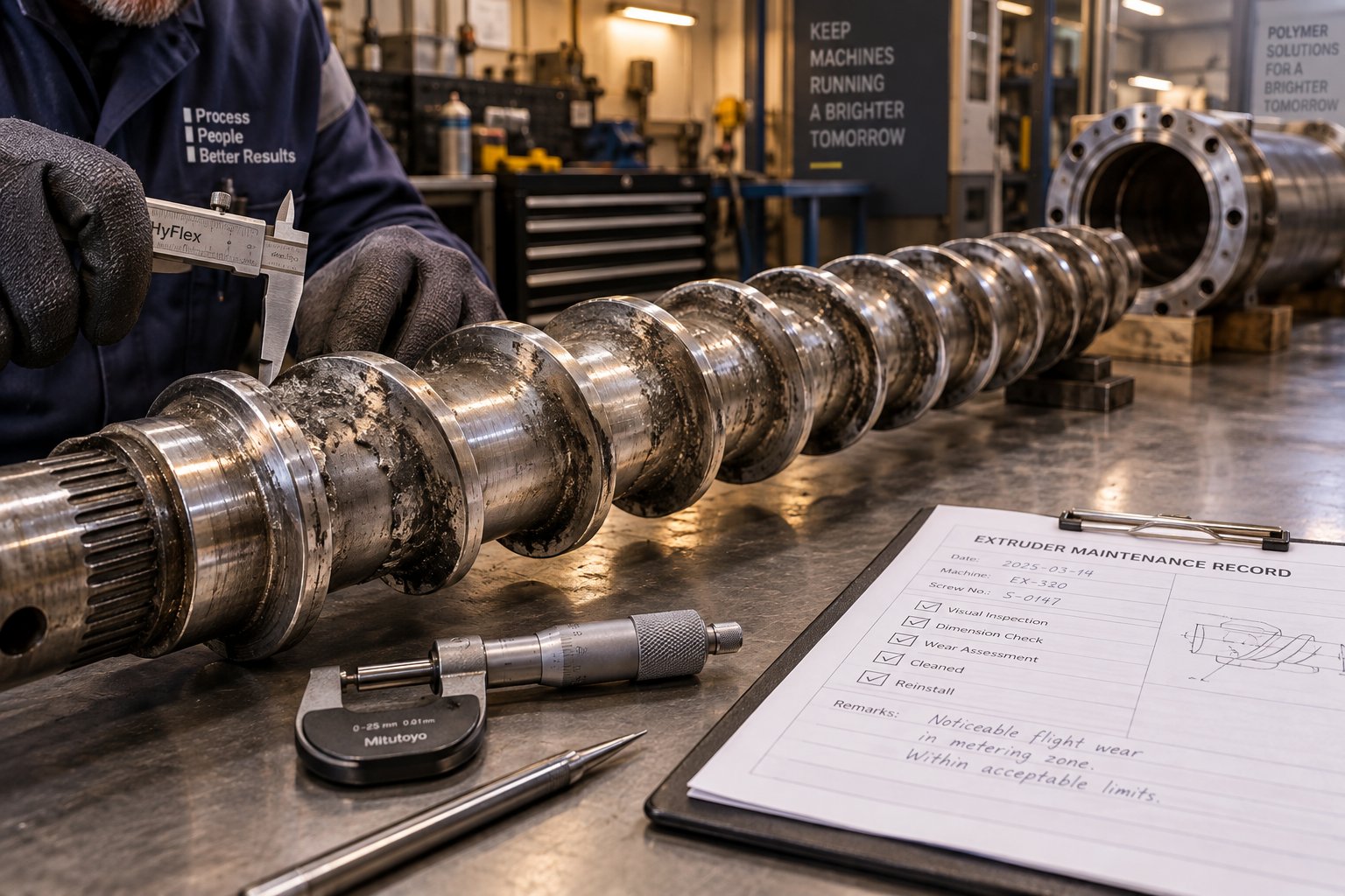
Maintenance, Troubleshooting, and Operational Costs for Film Extruders
Screw flights lose a fraction of a millimeter. A heater band drifts two degrees off setpoint. A chill roll bearing develops a faint vibration. Individually, none of these issues halt production - but left unchecked, they compound into gauge variation, rising scrap rates, ballooning energy bills, and eventually unplanned downtime that costs far more than any preventive maintenance program ever would. The blown film extrusion process - and its cast film counterpart - depends on dozens of components holding tight tolerances simultaneously. Managing that reality is not optional; it is the difference between a profitable operation and one bleeding margin from every roll.
Preventive Maintenance Fundamentals
Think of your film extruder the way a pilot thinks about pre-flight checks: systematic, non-negotiable, and documented. A disciplined maintenance routine does not just prevent breakdowns - it preserves the film quality your customers expect and protects the economics of every production hour.
Startup and shutdown procedures deserve special attention because they represent the moments when thermal stress and mechanical strain peak. On startup, bring barrel heaters to setpoint temperatures and allow adequate soak time before engaging the screw drive. Running a cold or partially melted barrel risks excessive torque loads on the extruder gearbox and can shear unmelted pellets into the melt stream, producing gels and contamination in your first rolls. On shutdown, purge the barrel and die thoroughly with a clean base resin or purging compound. Residual polymer left in the system degrades over time, generating charred particles and discoloration on the next startup - problems that Davis-Standard's troubleshooting guidance traces directly back to inadequate purging protocols.
Between startups and shutdowns, continuous monitoring of a handful of key process parameters gives you the earliest warning signs of trouble:
- Melt temperature - Tracks thermal uniformity in the extrudate. A rising trend at constant screw speed often signals screw or barrel wear increasing shear heat.
- Melt pressure (at the die inlet) - Stable pressure indicates consistent output. Fluctuations suggest feed inconsistency, partial screen blockage, or screw wear.
- Motor amperage - Reflects the mechanical load on the drive. Gradual increases at the same output rate point to higher viscosity from temperature drift or contamination; sudden spikes can indicate foreign material or mechanical binding.
- Line speed and haul-off tension - Directly affects film thickness and orientation. Any drift here shows up as gauge variation in the finished roll.
Daily visual checks of the air ring, die lips, collapsing frame alignment, and nip roller condition round out the routine. Swallow Machinery recommends weekly inspection of cooling system components, monthly calibration verification of temperature sensors and pressure transducers, and quarterly deep-cleaning of die internals and screen changer assemblies. Keeping a logbook - or better yet, a digital maintenance management system - turns these individual checks into a traceable history that helps you spot recurring patterns before they escalate.
Even with solid preventive habits, defects happen. When they do, fast, accurate troubleshooting saves hours of lost production. The table below maps the most common blown films and cast film defects to their probable causes and corrective actions, drawn from industry best practices:
| Film Defect | Probable Cause(s) | Corrective Action(s) |
|---|---|---|
| Gels or un-melts | Overheated/degraded polymer; worn screw or barrel allowing poor melting; foreign contamination in resin stream | Reduce melt temperature (for degradation) or increase barrel temps (for un-melts); inspect screw and barrel dimensions; check resin handling for contamination |
| Melt fracture ("sharkskin") | Melt temperature too low; die gap too narrow for the resin viscosity | Raise melt or die lip temperature; increase die gap; consider a polymer processing additive (PPA) as a last resort |
| Poor or uneven optical clarity | Inadequate or non-uniform quenching; IBC air leaks; air ring not centered | Raise melt temperature slightly; check air ring centering and airflow uniformity; verify IBC supply and exhaust tubes are properly seated; inspect for blocked plenums or dirty coil filters |
| Gauge bands or die lines | Contamination at die lips; die gap out of adjustment; non-uniform cooling; off-center bubble or nip | Clean die lips; re-gap die; center air ring and collapsing frame; confirm all transport rollers rotate freely |
| Voids, "raindrops," or gray streaks | Moisture in the resin stream | Identify moisture source in material handling system; verify raw material dryness with a heated moisture balance; ensure dryer is functioning properly |
| Wrinkles before the nip | Bubble instability; collapsing frame angle incorrect; bubble cage too tight or too loose; inconsistent cooling air | Stabilize extrusion output and melt temperature; adjust collapsing frame angle (decrease for edge wrinkles, increase for center wrinkles); verify cage centering and contact; check chiller and blower stability |
| Film blocking (layers stick together on roll) | Winding tension too high; corona treatment level excessive; inadequate film cooling; insufficient anti-block additive | Reduce winding tension; lower treatment levels; reduce cooling roll temperature or line speed; increase anti-block concentration |
| Discoloration | Extrudate melt temperature excessively high | Lower barrel temperatures to recommended levels for the resin being processed |
Notice how many of these defects trace back to either thermal management or component wear. That connection leads directly to the other half of the operational equation: understanding what drives your costs and how to control them.
Managing Operational Costs and Component Longevity
When you break down the cost of blowing film or running a cast line hour after hour, three categories dominate the budget: energy consumption, resin waste, and wear-part replacement. Everything else - labor, overhead, logistics - matters, but these three determine whether your per-kilogram production cost stays competitive or drifts upward.
Energy consumption is the largest recurring expense. The extruder motor and barrel heaters together account for the bulk of electrical demand on a film extrusion line. On older DC-drive systems, motor efficiency degrades over time, and oversized heaters compensate for heat lost through worn insulation or poor barrel contact. Upgrading to servo-driven extruders can cut drive energy by 40-50%, and ensuring heater bands maintain full surface contact with the barrel prevents wasted thermal energy. Monitoring motor amperage trends also reveals hidden costs - as Plastics Technology notes, a worn screw forces operators to increase RPM to maintain output, which directly raises energy consumption per kilogram of film produced.
Resin waste hits the bottom line from multiple angles. Startup and shutdown purge material, edge trim that is not recycled, off-spec film from gauge drift, and scrap generated during changeovers all represent purchased resin that never becomes saleable product. Inline edge trim recycling systems recover a significant portion of this waste, and gravimetric blending ensures precise additive and masterbatch dosing - eliminating the over-dosing that volumetric systems inevitably produce. Tighter process control through automated gauge management further reduces the material waste embedded in over-gauged film that technically passes specification but uses more resin than necessary.
Wear-part replacement is the cost category most processors defer - and most regret deferring. The plastic film extruder screw and barrel are in constant metal-to-polymer contact under high pressure, high temperature, and abrasive conditions. Wear is gradual and often invisible until performance degradation becomes undeniable. As the radial clearance between screw flights and barrel wall increases, leakage flow allows molten polymer to slip backward over the flights rather than being pumped forward. The consequences cascade: output drops, melt temperature rises from increased shear on the recirculating material, energy consumption climbs as operators raise RPM to compensate, and film gauge uniformity deteriorates because the screw can no longer deliver stable volumetric flow.
A useful rule of thumb from experienced screw manufacturers considers flight clearance at four times the original tolerance to be the threshold for replacement - though higher-viscosity resins like PE tolerate slightly more wear than lower-viscosity materials like PP before output loss becomes significant. The key is not to wait for that threshold. Baseline your screw and barrel dimensions when they are new, then measure periodically during planned shutdowns. Tracking wear trends lets you schedule replacements proactively rather than reactively - avoiding the far higher cost of emergency downtime.
When it is time to replace, sourcing precision-manufactured components from a specialist supplier matters more than many processors realize. Generic or poorly toleranced barrels and screws may fit the machine but fail to restore original performance. NANHAIYA provides custom and replacement single screw barrels designed for film extrusion lines as well as pipe, sheet, pelletizing, and recycling applications - a breadth that benefits processors running diverse operations who need a single supplier capable of matching metallurgy, dimensional tolerances, and screw geometry to each specific machine and resin profile. Their focus on film extruding applications means barrel specifications are engineered for the thermal stability and bore consistency that tight-gauge film production demands.
Proactive barrel and screw maintenance is not a maintenance expense - it is a quality investment. Every millimeter of uncontrolled wear erodes output rate, inflates energy cost, and degrades film consistency. Replacing worn components before performance visibly suffers protects both product quality and production economics far more cost-effectively than reactive repairs after scrap rates spike.
The blown film process - and every variant of the cast and co-extrusion process alongside it - ultimately rewards operators and managers who treat maintenance as a strategic function rather than a reluctant afterthought. Monitor your key parameters. Document your wear data. Build relationships with component suppliers who understand your specific line and resin demands. And resist the temptation to squeeze one more month from a screw that is already past its performance window. The film coming off your winder tells the whole story - and your customers will read it clearly.
Frequently Asked Questions About Plastic Film Extrusion Machines
1. What is the difference between blown film and cast film extrusion?
Blown film extrusion pushes molten resin through an annular die and inflates it into a vertical bubble, producing film with balanced biaxial strength ideal for bags, agricultural covers, and stretch wrap. Cast film extrusion forces the melt through a flat slot die onto chilled rollers, yielding film with superior optical clarity and tighter gauge tolerance suited to food wrap, medical packaging, and lamination. The choice depends on whether your priority is mechanical toughness (blown) or visual clarity and high-speed output (cast).
2. How do I choose the right plastic film extrusion machine for my application?
Start with your end-use product requirements rather than browsing equipment catalogs. Identify the resin you need, the film thickness range, target output in kg/hr, and whether barrier or multi-layer properties are required. Map these needs to a machine type - blown for toughness and versatility, cast for clarity and speed, co-extrusion for barrier packaging. Then size the extruder screw diameter, motor power, and cooling system to match your specific throughput target. Always evaluate total cost of ownership including installation, auxiliaries, energy, training, and wear-part replacement - not just the machine purchase price.
3. What resins can be processed on a plastic film extrusion machine?
The most commonly processed resins are polyolefins such as LDPE, LLDPE, HDPE, and PP, which cover the majority of commodity film applications. Engineering resins like PA (nylon) and EVOH are used as barrier layers in co-extruded structures for food and pharmaceutical packaging. PVC is processed on dedicated lines with corrosion-resistant barrels. Biodegradable polymers like PLA and PBAT are emerging alternatives that require modified screw designs and lower processing temperatures. Each resin demands specific barrel temperature profiles, screw compression ratios, and die geometries for optimal film quality.
4. How often should extruder screws and barrels be replaced on a film line?
There is no fixed calendar interval because wear rates depend on the resin type, fillers, throughput, and operating conditions. A practical approach is to baseline screw and barrel dimensions when new, then measure periodically during planned shutdowns. Many experienced manufacturers consider replacement necessary when flight clearance reaches roughly four times the original tolerance. Tracking wear trends lets you schedule replacements proactively - avoiding emergency downtime and the gradual output loss, rising energy costs, and gauge inconsistency that worn components cause. Suppliers like NANHAIYA offer custom and replacement single screw barrels engineered for film extrusion lines at nhyscrews.com.
5. What are the main causes of film defects in blown film extrusion?
Common defects trace back to thermal management and component wear. Gels and un-melts result from degraded polymer or insufficient melting due to a worn screw. Melt fracture or sharkskin appears when melt temperature is too low or the die gap is too narrow for the resin viscosity. Gauge bands indicate contamination at die lips or off-center bubble alignment. Wrinkles before the nip point to bubble instability or incorrect collapsing frame angles. Moisture in resin causes voids and gray streaks. Systematic monitoring of melt temperature, melt pressure, motor amperage, and line speed provides the earliest warning signs, while a structured troubleshooting approach pinpoints root causes quickly.
Written by
Nanhaiya Technical Team
Zhoushan Nanhaiya Plastic Machinery Co., Ltd.
The Nanhaiya technical team supports screw and barrel manufacturing projects through application review, technical communication, custom manufacturing coordination, and production and quality control.
Discuss Your Application
Related Articles
More insights on screw barrel technology and plastics processing.

What Nobody Tells You About Screw Barrel For Plastic Machine Design
Oct 10, 2026
Learn how screw barrel for plastic machine design affects melt quality, throughput, and wear life. Covers geometry, resin matching, troubleshooting, and sourcing.
Read Article
Single Screw Extruder for Sheet: Stop Guessing, Start Specifying
Oct 9, 2026
Learn how to specify a single screw extruder for sheet production. Covers screw geometry, resin-specific processing, troubleshooting, and maintenance best practices.
Read Article
PE Pipe Extruder Machine: What Datasheets Won't Tell You
Oct 9, 2026
Learn how a PE pipe extruder machine works, key specs explained, material grade selection, maintenance tips, and buyer guidance beyond the datasheet.
Read ArticleLooking for something else?
Search by material, symptom or product and jump straight to the relevant page.
These are navigation suggestions based on keyword matching — not a quotation, not a delivery commitment, and not a substitute for engineering review. Final specification is confirmed by our engineers against your drawings and processed material.
Need help with screw barrel selection?
Share your machine model, processed material and application. Our team can help with pricing and technical support.