

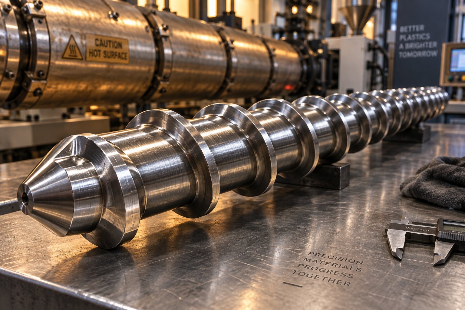
了解塑料挤出螺杆及其对性能的影响
您所接触到的每一种聚合物产品——管道、薄膜、片材、管材或型材——都始于送入加热料筒的原料颗粒。在料筒内部,一个旋转部件几乎承担了所有繁重的工作:塑料挤出螺杆。它将固体颗粒向前输送,产生摩擦热和粘性热使其熔化,将熔体混合成均匀的流体,并产生足够的压力将其推过成型模具。螺杆设计得当,就能实现更高的产量、更小的公差和更低的能耗。反之,则会面临诸多质量问题,而这些问题即使通过后续的调整也无济于事。
塑料挤出螺杆是一种螺旋状的精密加工轴,它在加热的料筒内旋转,用于输送、熔化、混合和加压聚合物材料,以便通过挤出模具进行连续成型。
本指南是一份技术严谨、厂商中立的资源。它涵盖了螺杆几何形状、长径比选择、压缩比基础知识、所有主要螺杆类型、聚合物与螺杆的匹配、表面涂层以及完整的系统集成——您自信地选择或评估挤出机螺杆所需的一切信息。
什么是塑料挤出螺杆?
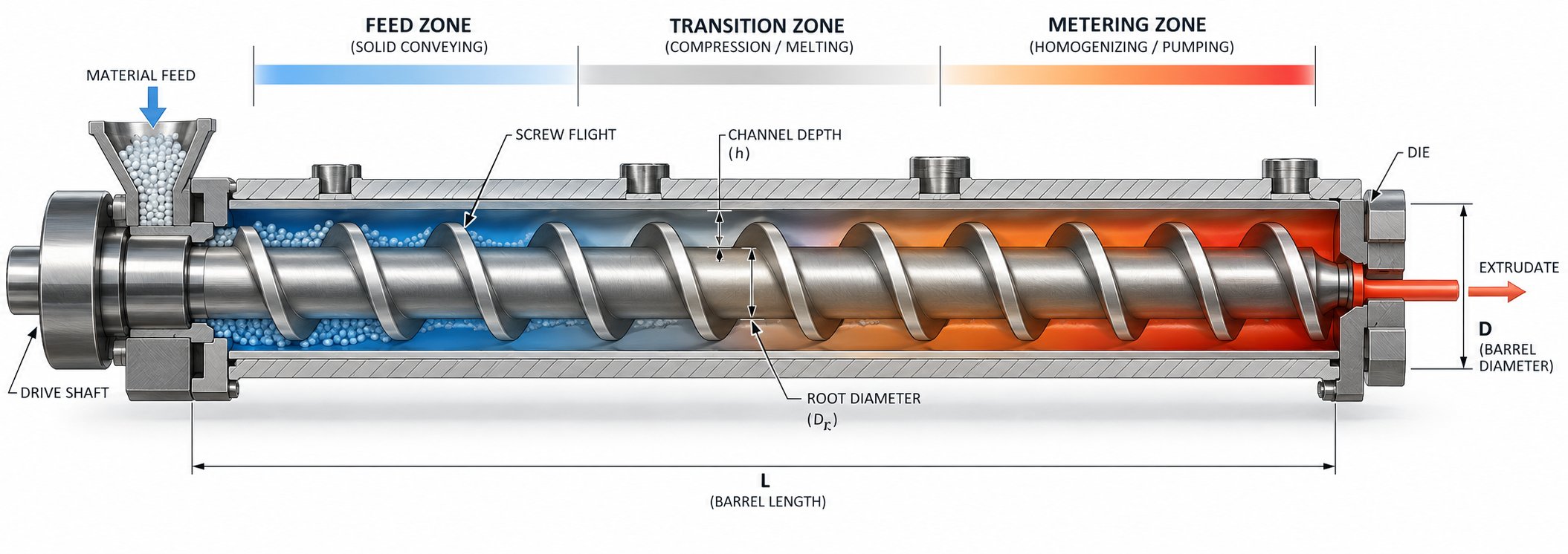
想象一下,螺杆是由三个独立的工位串联排列在同一根轴上。在克里斯·劳文达尔的《聚合物挤出》一书中概述的经典框架中,这些工位分别被称为进料区、过渡(压缩)区和计量区。
- 进料区——此处通道深度恒定且相对较深,用于接收料斗中的固体颗粒或粉末并将其向前输送。正如艾伦·格里夫在其《塑料挤出操作手册》中所解释的那样,该区域的深度必须足够,才能有效地接收塑料颗粒并将其向下游输送。
- 过渡(压缩)区——在此区域,通道逐渐变浅,挤压软化的颗粒并排出滞留的空气。深度的减小会产生压力,阻止气泡进一步向下移动,迫使聚合物完全熔融。
- 计量区——此时塑料几乎或完全熔化。通道深度保持恒定,但比进料深度浅得多,从而产生精确的剪切力和压力,以稳定的流速将均匀的熔体输送到模具。
This three-zone architecture applies to the vast majority of single-screw extruders. Twin-screw systems use modular elements — conveying segments, kneading blocks, and reverse elements — to accomplish similar functions, but the underlying principle remains the same: control how energy and pressure are applied to the polymer as it travels from hopper to die.
Why Screw Design Matters More Than You Think
You'll often hear processors focus on barrel heaters, die geometry, or downstream cooling when troubleshooting quality issues. Yet the screw plastic extruder combination is where melting rate, mixing quality, pressure generation, and melt temperature uniformity are fundamentally determined. A poorly matched extrusion screw can produce unmelted particles, excessive shear heating, inconsistent output, or degraded resin — problems no barrel temperature adjustment will fully resolve.
Consider a simple thought experiment: two identical extruders running the same resin at the same RPM, differing only in screw design. One may deliver a perfectly homogeneous melt at target temperature; the other may surge, overheat, or leave unmelted gels in the product. The screw is that consequential.
Throughout this guide, you'll learn exactly how geometric parameters like flight depth, pitch, and helix angle shape conveying and shear behavior, how to select the right L/D ratio and compression ratio for your polymer, and how to match screw type and surface treatment to your specific application. Each section builds on the last, moving from foundational geometry into practical, material-specific recommendations.
The starting point for all of those decisions is the screw's physical geometry — the precise dimensions that dictate how every pellet is conveyed, compressed, and transformed into a usable melt.
Screw Geometry Specifications That Control Extrusion Performance
Every aspect of how a plastic extrusion screw conveys, compresses, and melts polymer comes down to a handful of measurable geometric parameters. Change any one of them — even slightly — and you shift the balance among conveying capacity, shear rate, residence time, and pressure generation. Understanding these dimensions is what separates informed screw specification from educated guessing.
Flight Depth, Pitch, and Helix Angle Explained
Picture the screw rotating inside the extruder barrel. The helical ridge wrapping around the shaft is the flight, and the space between consecutive flights is the channel where polymer actually travels. Each geometric feature of that flight-and-channel system plays a distinct role in processing behavior.
- Flight depth (channel depth) — the distance from the top of the flight to the screw root. Deeper channels hold more material per turn, boosting solids conveying capacity in the feed zone. Shallower channels in the metering zone increase shear rate and improve heat transfer into the melt. As NC State Extension research confirms, decreasing either channel depth or width increases the shear applied to the material.
- Pitch — the axial distance from one flight to the next. Most screws use a square-pitch design, meaning the pitch equals the screw's nominal diameter. This convention makes it easy to determine L/D simply by counting turns. Increasing pitch moves material faster per revolution but reduces the time available for melting and mixing in any given barrel zone.
- Helix angle — the angle the flight makes relative to a plane perpendicular to the screw axis. For a square-pitch screw, this angle works out to approximately 17.66°. Steeper helix angles increase axial conveying velocity; shallower angles extend residence time and boost shear.
- Flight width (land width) — the thickness of the flight measured along the screw axis. Allan Griff notes in his Plastics Extrusion Operating Manual that flight width is typically around 10% of the extrusion barrel diameter. Wider lands waste effective screw length and generate excess heat in the clearance gap, while narrower lands allow too much melt to leak backward past the flight tip.
The table below consolidates these relationships so you can see how each parameter influences processing at a glance.
| Parameter | Definition | Typical Range | Effect on Processing |
|---|---|---|---|
| Flight Depth (Feed Zone) | Radial distance from flight tip to screw root in the feed section | Deepest zone; sized to accept pellets efficiently | Deeper channels increase solids conveying capacity and throughput potential |
| Flight Depth (Metering Zone) | Same measurement in the final constant-depth section | Significantly shallower than feed — sets compression ratio | Shallower channels raise shear rate, improve melt homogeneity, and build pressure |
| Pitch | Axial distance between consecutive flights | Commonly equal to screw diameter (square pitch) | Larger pitch increases conveying speed; smaller pitch extends residence time |
| Helix Angle | Angle of flight relative to a plane perpendicular to the axis | ~17.66° for square-pitch designs | Steeper angles accelerate axial flow; shallower angles boost shear input |
| Flight Width (Land) | Axial thickness of the flight crest | ~10% of barrel diameter | Wider lands increase frictional heat and reduce effective channel volume; narrower lands raise leakage flow |
Flight Clearance and Its Impact on Leakage Flow
Between the outermost edge of each flight and the inner wall of the barrel extruder, a small radial gap exists — the flight clearance. This gap is intentionally tight but never zero. On new screws, Griff reports clearances typically fall between 0.005 and 0.010 inches (0.125 to 0.25 mm), with smaller values for miniature extruders and larger values for very big machines.
Why does this tiny gap matter so much? Molten polymer under pressure will always try to flow backward through the clearance — a phenomenon called leakage flow or pressure-driven backflow. Tighter clearance reduces that leakage, improving volumetric pumping efficiency and melt quality. However, an excessively tight fit raises manufacturing cost and generates more viscous heat in the clearance itself, which can degrade heat-sensitive polymers.
Wear compounds the problem. As the flight tips erode over thousands of hours against the hardened extruder barrel lining, clearance opens up. The result is a gradual decline in pumping efficiency: you'll notice that the screw must turn faster to maintain the same output, generating more heat and less consistent melt pressure. That is why monitoring clearance wear is one of the most practical diagnostics in any extrusion operation — a topic explored in detail later in this guide.
Root Diameter Progression Across Zones
If you could look at the screw in cross-section from feed end to discharge, you'd see the root — the solid cylindrical core beneath the flights — gradually growing in diameter. The feed zone root is narrow, creating deep channels that swallow pellets. Moving into the transition zone, the root tapers wider, steadily reducing channel depth and compacting the softening polymer. By the metering zone, the root reaches its maximum diameter, and the shallow channel delivers high shear and consistent pressure.
This progressive taper is what physically creates compression. The ratio of the feed-zone channel depth to the metering-zone channel depth defines the compression ratio — a critical design variable that must be matched to each polymer's density change from solid pellets to melt. Too steep a taper and you generate excessive shear heating; too gradual and the polymer may never fully compact.
Choosing the right compression ratio is, in many ways, the most polymer-specific decision in screw design — and it hinges on understanding the bulk density characteristics of every resin you plan to run.
L/D Ratio Selection Guide for Different Polymers and Applications
Compression ratio tells you how aggressively the screw compacts material — but it says nothing about how much barrel length the polymer gets to absorb heat, undergo mixing, and reach a uniform melt state. That is the job of the L/D ratio, and selecting it incorrectly is one of the most expensive mistakes a processor can make. A screw extruder that is too short for the application will spit out unmelted pellets no matter how perfectly the compression ratio is tuned. One that is too long will waste energy, degrade heat-sensitive resins, and inflate capital costs for no measurable gain.
What L/D Ratio Means and How It Is Measured
L/D ratio is simply the functional flighted length of the screw divided by its outer diameter at the flight crest. A screw with a 1,500 mm working length and a 50 mm outer diameter has an L/D of 30:1. Sounds straightforward, but a few details trip people up when comparing specs across screw extruders from different manufacturers.
- Effective length is the flighted portion — measured from the rear edge of the feed throat to the screw tip. Total mechanical length, which includes the shank and drive connection, is always longer and should not be used for comparison.
- Diameter refers to the outer diameter at the flight crest, not the root diameter.
- For twin-screw systems, L/D is conventionally measured as barrel cylinder length divided by barrel bore diameter, since the screws share an intermeshing geometry.
Why does this single number receive so much engineering attention? Because L/D effectively sets the residence time of polymer inside the barrel at any given screw speed. Residence time, in turn, controls how much heat the material absorbs, how thoroughly it mixes, how completely volatiles escape during venting, and whether any unwanted thermal reactions have time to occur. A 24:1 barrel and a 36:1 barrel running the same RPM will produce dramatically different melt quality from identical resin — the longer barrel provides roughly 50% more residence time, more flight surface area for shear work, and more opportunity for conductive heat transfer from the heated barrel wall.
L/D also determines how much real estate is available for the screw's functional zones. A short barrel forces feed, compression, metering, and any mixing or venting sections into a cramped space. A longer barrel lets you stage those functions deliberately, dedicating adequate length to each.
Matching L/D Ratio to Polymer Type and Application
Here is where most guides fall short: they list L/D ranges without explaining why each range exists. The logic is actually intuitive once you understand what each extra unit of L/D buys — and what it costs.
The table below maps common L/D ranges to specific applications, the polymers they serve, and the engineering reasoning behind each selection. These ranges reflect industry-conventional starting points for OEM and replacement screw extrusion projects — not absolute rules. Final L/D should always be validated against your specific resin grade, additives, and output target.
| L/D Ratio Range | Typical Applications | Polymer Suitability | Key Tradeoffs |
|---|---|---|---|
| 18:1 – 22:1 | Rigid PVC pipe and profile (counter-rotating twin screw); injection molding plastication | Heat-sensitive PVC compounds; pre-compounded materials needing minimal residence time | Minimizes thermal degradation risk; limits mixing capacity and throughput ceiling |
| 20:1 – 24:1 | Flexible PVC profile; general-purpose extrusion of pre-compounded resins; recycling and pelletizing of clean regrind | PVC with plasticizer; materials requiring only moderate melting and mixing | Compact footprint and lower cost; insufficient for polymers needing extensive melting or venting |
| 24:1 – 30:1 | PE and PP pipe, sheet, and profile; wire and cable insulation; general-purpose polyolefin processing | LDPE, HDPE, LLDPE, PP — thermally stable resins that tolerate longer residence | Good balance of melting capacity and energy efficiency; may fall short for vented or highly filled applications |
| 28:1 – 32:1 | Blown film (HDPE/LLDPE); PET sheet and film (vented); engineering resins (PC, PA, ABS) | High-melting-point polymers; hygroscopic resins requiring a vent zone for moisture removal | Supports vent section and thorough melting; higher barrel and screw cost; increased energy draw |
| 30:1 – 36:1 | High-output polyolefin lines; moderately filled compounds; single-screw applications demanding extensive mixing | PE, PP, and engineering resins at elevated throughputs | Maximum practical L/D for most single-screw extruders before shaft deflection becomes a design constraint |
| 36:1 – 48:1 | Co-rotating twin-screw compounding; devolatilization; reactive extrusion; masterbatch production | Virtually all thermoplastics when compounding, blending, or devolatilizing | Modular screw elements allow staged mixing and multiple feed/vent ports; significantly higher capital cost |
| 48:1 – 60:1+ | High-shear specialty compounding; difficult pigment dispersion; reactive extrusion with slow kinetics | Specialty compounds requiring maximum mixing intensity or extended reaction residence time | Highest flexibility for complex screw element configurations; greatest cost and floor space demand |
A few patterns emerge from this table. Thermally stable polyolefins like PE and PP tolerate — and often benefit from — longer barrels because extra residence time improves melt homogeneity without degradation risk. Engineering resins such as PA and PC land in the 28:1–32:1 band largely because they have high melting points and often arrive with moisture that must be vented mid-barrel. And PVC sits at the short end of the spectrum because it degrades rapidly above roughly 200 degrees Celsius; every additional unit of L/D adds residence time the stabilizer package must fight against.
When Longer Is Not Better
It is tempting to default to the longest L/D available — "more melting capacity can't hurt, right?" In reality, over-specifying L/D introduces several concrete penalties.
- Heat-sensitive PVC processing — Rigid PVC formulations are engineered around minimizing thermal exposure. Pushing L/D beyond 22:1 on a counter-rotating twin screw extruder forces the compound to spend more time at elevated temperatures, overwhelming thermal stabilizers and producing discoloration or outright degradation.
- Pre-compounded and masterbatch materials — When the hard mixing work was done upstream in a compounding step, the extrusion screw only needs to re-melt and pump. Running these materials through a 36:1 barrel wastes floor space, energy, and maintenance budget.
- Short-run and quick-change operations — Shorter barrels purge faster, clean out more easily during color changes, and reduce scrap during transitions. In a production environment with frequent changeovers, every extra foot of barrel length translates directly into lost time and wasted resin.
- Capital and replacement economics — A 36:1 extrusion line can cost 30–50% more than an equivalent 24:1 setup, accounting for additional steel, heating zones, cooling channels, drive motor sizing, and floor space. Replacement screws are proportionally more expensive as well.
- Mechanical limits on single-screw designs — Beyond roughly 36:1, torsional load and shaft deflection become significant engineering constraints for single screw extruders. This is why single-screw L/D rarely exceeds 40:1 in production machines, while co-rotating twin-screw systems — built on splined shafts with modular elements — routinely reach 48:1 and beyond.
A practical rule of thumb: add L/D only where you can assign a specific function to the additional length — an extra mixing section, a vent port, a side-feed zone. If you cannot describe what those extra four diameters of barrel will do, the added cost is unjustified.
Of course, L/D is only half the picture. A 30:1 screw with the wrong compression ratio for your polymer will still produce surging, unmelts, or degradation. The two parameters must be selected together — and compression ratio brings its own set of polymer-specific rules that deserve careful attention.
Compression Ratio Explained and How to Choose the Right One
L/D ratio determines how long the polymer stays inside the barrel. The extrusion screw compression ratio determines how hard the screw squeezes that polymer along the way. These two parameters are independent — a screw can be long with gentle compression or short with aggressive compression — and both must be matched to the resin you're running. Yet compression ratio is the one processors most frequently get wrong, often because they borrow a number from a different machine or a different material and assume it will transfer.
Defining Compression Ratio in Screw Design
The concept is deceptively simple. Compression ratio equals the channel depth in the feed zone (H1) divided by the channel depth in the metering zone (H2). A screw with a 9 mm deep feed channel and a 3 mm deep metering channel has a 3:1 compression ratio. As material spirals from the deep feed section into the progressively shallower transition zone, that shrinking channel volume does three things simultaneously: it compacts loose pellets into a solid bed, presses that bed against the hot barrel wall to accelerate conductive melting, and generates shear heat through internal friction.
That last point is the one most people overlook. Industry experts stress that the compression ratio must be established not only to feed enough solid polymer, but also to introduce enough shear heating to complete melting. A 4:1 ratio puts roughly twice the shear energy into the melt compared to a 2:1 ratio — which is exactly why heat-sensitive resins need low compression and why tough-to-melt polymers demand more.
So how do you pick the right number? The guiding principle ties directly to the physical properties of your feedstock:
The compression ratio should approximate the ratio of bulk density of the solid feed to the melt density of the polymer, ensuring the metering channel stays completely filled and pressurized without generating excessive shear heat.
Loose pellets contain trapped air between particles, giving them a lower bulk density than the fully compacted melt. The screw must compress that volume difference away. A polymer whose pellets have a very low bulk density relative to its melt density — imagine light, fluffy regrind versus dense molten polyethylene — requires a higher compression ratio to close the gap. Conversely, a dense, tightly packed powder feeding into a polymer with a relatively similar melt density needs less volumetric reduction.
Compression Ratio Ranges by Polymer Family
Every polymer family has a characteristic bulk-density-to-melt-density relationship, and that relationship anchors the starting compression ratio for any screw barrel design. The table below maps common polymer families to their typical ranges, drawing on established industry guidance and published density data.
| Polymer Family | Bulk Density Characteristic | Typical Compression Ratio | Notes |
|---|---|---|---|
| PE (HDPE, LDPE, LLDPE) | Moderate bulk density (~0.55–0.60 g/cm³ for pellets); melt density ~0.75–0.78 g/cm³ | 3.0:1 – 4.0:1 | Thermally tolerant; higher compression needed to melt fully. HMWPE grades may require grooved-feed barrels due to low friction. |
| PP (Homo & Copolymer) | Similar to PE; pellet bulk density ~0.55–0.60 g/cm³; melt density ~0.73–0.77 g/cm³ | 3.0:1 – 4.0:1 | Nucleated and filled grades may benefit from barrier screw designs with added mixing sections. |
| PS (GPPS, HIPS) | Higher pellet bulk density than polyolefins; melt density ~0.97–1.00 g/cm³ | 2.5:1 – 3.0:1 | Shear-sensitive — excessive compression raises melt temperature and risks degradation in HIPS. |
| ABS | Moderate-to-high bulk density; melt density ~1.02–1.06 g/cm³ | 2.5:1 – 3.0:1 | Requires moderate shear; too-high ratios can degrade the butadiene rubber phase and reduce impact strength. |
| PA (Nylon 6, 66) | Relatively high pellet bulk density; melt density ~1.01–1.08 g/cm³ | 3.0:1 – 3.5:1 | Hygroscopic — often paired with vented (two-stage) extruder screw barrel configurations to remove moisture mid-process. |
| PC (Polycarbonate) | High pellet bulk density; melt density ~1.06–1.12 g/cm³ | 2.5:1 – 3.0:1 | High melt viscosity demands adequate shear without overheating; sensitive to hydrolytic degradation if moisture is present. |
| POM (Acetal) | Dense pellets; melt density ~1.20–1.28 g/cm³ | 2.5:1 – 3.5:1 | Narrow processing window; generates formaldehyde if overheated. Precise temperature control is critical. |
| Rigid PVC | Powder or dry-blend form with low bulk density (~0.50–0.60 g/cm³); melt density ~1.30–1.45 g/cm³ | 2.0:1 – 2.5:1 | Extremely heat-sensitive. Low compression minimizes shear heating; longer stabilizer packages compensate. Never use a high-compression polyolefin screw for PVC. |
| PET (Polyethylene Terephthalate) | Moderate pellet bulk density; melt density ~1.20–1.30 g/cm³ | 2.5:1 – 3.5:1 | Moisture-sensitive; typically processed on vented screws or pre-dried. IV loss accelerates with excessive shear. |
| Fluoropolymers (PTFE, FEP, PFA) | Very high melt density (~2.1–2.2 g/cm³); pellet bulk density varies widely | 1.5:1 – 2.5:1 | Corrosive melt byproducts require specialized barrel and screw metallurgy. Low compression protects against decomposition. |
| Highly Filled / Glass-Fiber Compounds | Variable; filler increases effective bulk density | 1.8:1 – 2.5:1 (lower than base resin alone) | Filler particles contribute their own shear heating; reducing compression prevents overheating. Abrasive fillers demand wear-resistant screw barrel surfaces. |
A clear pattern runs through this table: heat-sensitive polymers cluster at the low end of the compression spectrum, thermally stable polyolefins occupy the high end, and engineering resins fall in between. The ratios above represent industry-conventional starting points for virgin pellet feedstock on conventional metering screws. Switching to regrind, flake, or powder — with its lower or inconsistent bulk density — often requires adjusting the ratio or adopting a grooved-feed barrel to maintain stable solids conveying.
Consequences of Incorrect Compression Ratio
When the compression ratio is mismatched to the polymer, the symptoms are predictable and split cleanly into two failure modes.
Compression Ratio Too High
Imagine forcing a heat-sensitive PVC compound through a screw designed for polyethylene. The deep-to-shallow channel transition generates far more shear energy than the resin can absorb safely. You'll see:
- Excessive melt temperature — the polymer exits the screw hotter than your barrel setpoints, because shear heat overwhelms the cooling system's capacity to remove it.
- Thermal degradation — discoloration, black specks, and burnt streaks appear in the extrudate. For PVC, this means release of HCl gas and a rapid cascade of decomposition.
- Surging and instability — if compression is so aggressive that the transition zone cannot melt material fast enough, alternating slugs of solid and melt reach the metering section, causing erratic output pressure.
- Reduced mechanical properties — excessive shear breaks polymer chains, lowering impact strength in ABS, reducing IV in PET, and compromising overall part performance.
Compression Ratio Too Low
The opposite problem produces its own set of headaches. A screw with insufficient compression for the polymer's bulk density change leaves the metering section partially empty and the melt inadequately processed:
- Incomplete melting — unmelted pellets or gels pass through the die and show up as visual defects or weak spots in the finished product.
- Poor pressure generation — the metering zone cannot build consistent head pressure because it is not fully packed with melt, leading to dimensional variation in the extrudate.
- Output surging — a partially starved metering channel pumps unevenly, producing periodic fluctuations in throughput that no downstream haul-off adjustment can fully compensate.
- Increased energy waste — barrel heaters work overtime to supply the melting energy the screw failed to generate mechanically, raising electricity consumption without improving melt quality.
The diagnostic shortcut is straightforward: if you see scorch or discoloration, suspect the ratio is too high for your material; if you see unmelts or gels, suspect it is too low. Surging can come from either extreme, so look at the accompanying symptoms to determine direction.
One critical caveat deserves emphasis: the compression ratio is not a standalone specification. It interacts with L/D, screw type, absolute channel depths, and section lengths. A barrier screw, for instance, separates the solid bed from the melt pool with a secondary flight, which fundamentally changes how compression functions — the metering depth can be optimized for head pressure and mixing independently of the feed depth. This is why selecting the right type of screw matters just as much as dialing in the right ratio, and why a comprehensive understanding of every available screw architecture gives you far more design flexibility than any single parameter ever could.
Every Type of Extrusion Screw and When to Use Each
Compression ratio and L/D set the screw's dimensional framework, but neither tells the full story. Two screws with identical ratios and lengths can deliver radically different melt quality depending on their flight architecture — the specific arrangement of channels, barriers, and mixing elements along the shaft. Choosing among these architectures is where polymer processing shifts from number-crunching into applied engineering, because each design solves a different melting, mixing, or conveying challenge.
Below is a complete catalog of major screw types used in modern extrusion. Whether you're evaluating a set of extruder screws for a new line or troubleshooting output quality on existing extruder screws and barrels, understanding these distinctions will sharpen every specification decision you make.
General-Purpose and Barrier Screw Designs
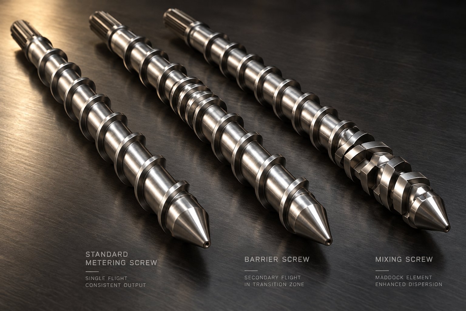
The standard metering screw — also called the general-purpose or conventional three-zone screw — is the simplest and most widely installed design in the industry. It uses a single flight winding from feed to discharge, with a constant-depth feed zone, a tapered transition zone, and a constant-depth metering zone. Its main advantages are low manufacturing cost, broad polymer compatibility with pre-compounded materials, and easy troubleshooting. The limitation? Melting relies entirely on conduction from the barrel wall and drag-induced shear, so performance drops sharply when the polymer demands rapid, high-volume melting or intensive mixing.
That limitation is precisely what barrier screws were invented to address. A barrier screw introduces a secondary flight — the barrier flight — in the transition zone, dividing the channel into two sub-channels: one carrying the remaining solid bed and the other collecting freshly formed melt. The barrier flight clearance is intentionally larger than the main flight clearance, allowing melt to pass over it into the melt channel while trapping solids on the other side. This physical separation prevents the solid bed from breaking apart and contaminating the melt pool — a common cause of unmelts, gels, and output surging on conventional screws.
Two principal barrier configurations dominate the market, as extrusion expert Jim Frankland explains:
- Crossing (Maillefer) barrier — One of the earliest barrier designs. The solids and melt channels cross paths along the screw length. The solids channel narrows gradually while the melt channel widens. This geometry avoids a sudden restriction at the barrier start, making it well suited for hard or slippery polymers whose fragile solid beds resist abrupt cross-section changes. It also tends to generate more head pressure due to its wider, shallower melt channel.
- Parallel (Barr) barrier — The solids and melt channels run roughly parallel along the barrier section. For a given axial length, this layout provides approximately one-third more surface area in the solids channel than the crossing type, translating to greater melting capacity. Polymers with higher energy requirements — high melting points, high specific heats, or strong shear-thinning behavior — generally perform better on parallel barrier designs.
A third variant, sometimes called the Dray-Lawrence type, increases the helix angle (lead) within the barrier section to push more volume through for higher output. Frankland notes that on a 3.5-inch screw, increasing the lead by 25% adds less than 10% to the melting area because the longer pitch reduces the number of flight turns. The real benefit is accommodating higher throughput — not boosting melting capacity per se — unless the axial length of the barrier section is also extended.
When should you pick a barrier over a conventional screw? Anytime the application demands higher output with consistent melt quality, particularly with semi-crystalline polyolefins (PE, PP) where controlled, progressive melting is critical. Conventional screws still earn their place on lines running pre-compounded materials at moderate throughputs where simplicity and quick changeovers outweigh raw melting performance.
Mixing Screws — Distributive vs Dispersive Elements
Melting the polymer is only half the challenge. If your process involves colorants, masterbatch letdown, liquid additives, or mineral fillers, you also need thorough mixing — and not all mixing is created equal. The distinction between distributive and dispersive mixing is fundamental to selecting the right element, yet many processors use the terms interchangeably.
Viplas engineering resources define the difference clearly: distributive mixing rearranges the components spatially so they spread uniformly through the melt without necessarily breaking particles down. Dispersive mixing applies high localized shear to reduce the size of agglomerates, gels, or undispersed pigment clusters. Most real-world applications need some combination of both — the question is which one dominates your requirements.
Distributive mixing elements split, recombine, and reorient melt streams repeatedly:
- Saxton mixer — Features helical secondary flights that divide the main channel into multiple sub-channels. Melt is split and recombined many times per revolution, producing excellent color homogeneity at relatively low pressure drop.
- Pineapple (pin) mixer — A series of pins protrude from the screw root, interrupting laminar flow and forcing the melt to divide around each pin. This design generates moderate shear, making it useful for shear-sensitive polymers that primarily need spatial homogenization rather than aggressive particle breakdown.
- Dulmage mixer — Consists of multiple rows of interrupted flights arranged in series. Each row forces the melt to redistribute before entering the next, offering strong distributive action in a compact axial length.
Dispersive mixing elements force melt through restrictive gaps that impose high shear stress:
- Maddock (LeRoy) mixer — The most widely used dispersive element on single-screw extruders. It features a series of longitudinal grooves separated by barriers (lands). Polymer enters through one set of channels, is forced over a narrow clearance barrier into a second set of channels, and exits. That barrier clearance determines the maximum shear stress applied to the melt, making it highly effective at breaking gels and dispersing difficult pigments.
- Blister ring — A simple cylindrical restriction machined onto the screw root, creating a uniform narrow gap around the full circumference. All melt must pass through this gap, receiving a high-shear "wipe." Blister rings are often placed upstream of a Maddock section or at the end of a barrier zone to ensure no unmelted solids reach the mixing stage.
So when does each type matter most? In plastic extrusion color process automation — where consistent pigment dispersion batch after batch is non-negotiable — dispersive elements like the Maddock mixer break pigment agglomerates down to their primary particle size, while a downstream distributive element like a Saxton or pineapple section spreads those particles uniformly. Masterbatch letdown operations, additive blending, and runs with recycled content all benefit from a similar two-stage mixing strategy.
Vented, Two-Stage, and Specialty Screw Designs
Beyond general-purpose, barrier, and mixing architectures, several specialty screw designs solve problems that no conventional flight geometry can address on its own.
- Vented (two-stage) screws — Designed for moisture removal and devolatilization without pre-drying. The screw has two compression-metering sequences separated by a deep-channel decompression zone aligned with an atmospheric or vacuum vent port in the barrel. The first stage melts the polymer and builds initial pressure; the decompression zone drops pressure sharply, allowing moisture and volatiles to flash off through the vent. The second stage re-pressurizes the degassed melt for pumping through the die. Hygroscopic engineering resins like nylon (PA) and PET are prime candidates, as are recycled streams with unpredictable moisture content.
- Pin-type mixing screws — Rows of cylindrical pins are inserted radially through the screw flights, disrupting the helical flow pattern and dramatically improving distributive mixing. Originally developed for rubber compounding and crosslinkable compounds (where uniform additive dispersion is essential to prevent premature crosslinking), pin mixing screws are also used in cable extrusion and thick-wall profile applications demanding exceptional homogeneity.
- Wave screws (Energy Transfer type) — The channel depth oscillates sinusoidally along the screw length, creating alternating peaks and valleys in both the primary and secondary channels. As material flows over these undulations, it is repeatedly compressed and decompressed, forcing molten polymer to the barrel wall for improved heat transfer and pushing unmelted solids into higher-shear regions. Wave screws can achieve melting efficiencies that rival barrier screws while maintaining lower melt temperatures — a significant advantage for thermally sensitive resins.
- Grooved-feed screws and barrels — Strictly speaking, the grooves are machined into the barrel's feed section, not the screw itself, but the screw must be designed in concert with them. Longitudinal grooves in the feed throat grip pellets and force positive conveying independent of barrel-surface friction. This decouples throughput from screw speed to a significant degree, enabling higher output per RPM. Grooved-feed designs are widely used in HDPE and PP blown-film lines where maximum throughput with tight gauge uniformity is the goal.
The summary below condenses each screw type into its primary advantage and ideal application for quick reference:
| Screw Type | Primary Advantage | Ideal Application |
|---|---|---|
| Standard Metering (Three-Zone) | Simplicity, low cost, broad compatibility | Pre-compounded resins at moderate throughput |
| Barrier — Maillefer (Crossing) | Gentle solids handling, good pressure generation | Hard or slippery polymers; lower-energy-requirement resins |
| Barrier — Barr (Parallel) | Higher melting surface area per unit length | High-output polyolefin and engineering resin lines |
| Maddock / LeRoy Mixer | High-shear dispersive mixing | Gel elimination, pigment dispersion, masterbatch letdown |
| Saxton / Dulmage Mixer | Excellent distributive homogenization | Color uniformity, liquid additive blending |
| Pineapple (Pin) Mixer | Moderate distributive mixing with low shear | Shear-sensitive polymers needing spatial homogeneity |
| Vented (Two-Stage) | In-line moisture and volatile removal | Hygroscopic resins (PA, PET), recycled feedstock |
| Pin-Type Mixing | Intensive distributive mixing through flow disruption | Rubber compounds, crosslinkable polymers, cable insulation |
| Wave (Energy Transfer) | High melting efficiency at lower melt temperature | Heat-sensitive resins requiring thorough melting |
| Grooved-Feed (barrel + matched screw) | Positive conveying decoupled from friction | High-output HDPE and PP blown film |
In practice, modern extruder screws rarely use a single architecture in isolation. A high-performance screw for blown-film LLDPE might combine a grooved-feed barrel section, a parallel barrier melting zone, a blister ring, and a Maddock dispersive mixer — each element addressing a specific stage of the melting and mixing process. Thinking of these designs as modular building blocks, rather than mutually exclusive categories, gives you the flexibility to tailor performance to any polymer or product geometry.
Screw architecture determines how the polymer is processed. The next logical question is whether one screw does the job alone — or whether you need two screws working together. The answer depends on whether your line demands simple melt pumping or intensive compounding, and that distinction drives the single-screw versus twin-screw decision more than any other factor.
Single Screw vs Twin Screw Extrusion — A Practical Comparison
A single screw inside a heated barrel can melt, mix, and pump most pre-compounded thermoplastics with impressive efficiency. But what happens when the job calls for blending two incompatible polymers, dispersing 50% calcium carbonate into a polyolefin matrix, or stripping residual solvent from a reactive compound mid-process? At some point, one screw simply runs out of mixing muscle — and that is where twin-screw technology enters the picture.
Choosing between these two platforms is not about picking a "better" machine. It is about matching the conveying and mixing mechanism to the specific demands of your material, your throughput target, and your budget. Let's break both options down so you can make that match with confidence.
Single Screw Extrusion — Strengths and Limitations
The single-screw extruder remains the workhorse of polymer processing for good reason. It dominates pipe, blown film, cast sheet, wire coating, and profile extrusion lines worldwide because it does three things exceptionally well: it pumps melt at high pressure with excellent volumetric consistency, it costs significantly less to purchase and maintain than twin-screw alternatives, and it is mechanically straightforward enough that operators can troubleshoot most issues on the production floor.
How does it actually move material? The mechanism is drag-induced conveying. Solid pellets dropped into the feed throat are gripped between the rotating screw flights and the stationary barrel wall. Friction between the barrel surface and the pellets drags the material forward — think of it like the screw-and-nut principle, where the barrel wall acts as the "nut" holding the polymer in place while the rotating screw advances it. This friction-dependent transport means that barrel surface finish, feed-throat temperature, and pellet geometry all influence conveying stability directly.
The strengths are substantial:
- Excellent pumping efficiency — For pre-compounded, fully formulated resins that only need remelting and pressurization, a single screw delivers steady output at high die pressures with minimal energy input per kilogram.
- Lower capital cost — A single-screw line typically costs 30–60% less than a comparable twin-screw system, depending on size and accessories.
- Simple drive train — One screw, one gearbox, one thrust bearing assembly. Maintenance intervals are longer and parts inventories smaller.
- Proven reliability — Decades of field experience across virtually every forming application mean that troubleshooting resources, replacement parts, and trained operators are widely available.
The limitations are equally clear. Because the single screw relies on barrel friction for conveying rather than positive displacement, throughput and screw speed are tightly coupled — you cannot easily increase one without affecting the other. Mixing capability, while improvable with barrier flights, Maddock elements, and pin sections discussed in the previous chapter, remains fundamentally limited by the single-channel flow geometry. The melt stream follows a helical path with relatively low strain redistribution, which is perfectly adequate for coloring pre-compounded pellets but inadequate for dispersing nanofillers, blending immiscible polymer alloys, or carrying out chemical reactions that demand precise residence-time control.
In short, if your feedstock arrives ready to melt and pump, a single-screw extruder is almost certainly the right tool. The moment your process requires the machine itself to do significant compounding work, you'll start feeling the limits of that single channel.
Co-Rotating vs Counter-Rotating Twin Screw Systems
A twin-screw extruder places two screws side by side inside a figure-eight barrel bore. That alone changes the physics dramatically — but which way those screws rotate relative to each other creates two fundamentally different machines.
Co-rotating intermeshing twin screws turn in the same direction. In a fully intermeshing co-rotating system, the flight of one screw wipes the root of the other, creating a self-cleaning action that virtually eliminates stagnant material and dead zones inside the barrel. This wiping behavior keeps the residence-time distribution narrow — critical for heat-sensitive compounds and reactive extrusion where even small pockets of stagnant melt can degrade or gel.
The mixing intensity is formidable. Material is subjected to high shear stress both between the two screws and between each screw and the barrel wall. When kneading blocks are introduced into the screw configuration, an additional elongational-flow component stretches the melt, which is especially effective at breaking apart filler agglomerates and dispersing nanoscale additives. Technovel's technical resources note that this combination of shear and elongational flow allows the co-rotating twin screw to achieve structural control — breaking up agglomerates, regulating phase morphology in polymer alloys, and promoting mass transfer in reactive systems.
Co-rotating machines dominate compounding, devolatilization, reactive extrusion, polymer blending, filler masterbatch production, and recycling operations. If you've ever seen a used twin screw extruder listed for compounding applications, odds are high it was a co-rotating intermeshing design.
Counter-rotating intermeshing twin screws spin in opposite directions. At the intermeshing zone, material is drawn inward between the screws and compressed — a mechanism often described as a calendering effect. Unlike the aggressive shear of co-rotating systems, counter-rotating screws disperse material through gentle compressive and elongational deformation. Shear stress stays comparatively low, and so does shear-induced heat generation.
Why does that matter? Consider rigid PVC — a polymer with a narrow gap between its processing temperature and its decomposition temperature. The high-shear environment of a co-rotating machine can push PVC past that threshold, triggering degradation. A counter-rotating twin screw extruder, operating at high fill and low rotational speed, keeps the material temperature well within the safe window. That is why counter-rotating designs are the standard for PVC pipe, sheet, and profile extrusion lines.
Modular screw element configurations give twin-screw systems their remarkable flexibility. Unlike a single-screw extruder, where the entire flight geometry is machined onto one monolithic shaft, a twin screw and barrel system uses segmented elements threaded onto splined shafts. Each element serves a specific function:
- Conveying elements — Standard helical flights that transport material forward. Varying the pitch changes conveying speed and fill level.
- Kneading blocks — Stacked disc-shaped elements offset at specific angles (30°, 60°, 90°). Wider offset angles increase shear intensity and mixing aggressiveness. Narrow-angle kneading blocks provide gentler distributive blending.
- Reverse elements — Flights or kneading blocks with a reversed helix that push material backward, creating a local seal or high-pressure zone. These are used to build backpressure before vent ports, ensuring volatiles escape efficiently during devolatilization.
By rearranging these building blocks along the shaft, a process engineer can design a completely customized processing profile — staging where melting occurs, where high-shear mixing is applied, where fillers are side-fed, and where vacuum devolatilization strips moisture or volatiles. This modularity is what makes the twin screw barrel system indispensable for product development: you can reconfigure the screw in hours to test a new formulation without machining a new shaft.
Choosing Between Single and Twin Screw Extruders
The decision ultimately comes down to what your process needs the extruder to do. If the machine's primary job is melting and pumping a known, pre-formulated compound into a die, single-screw economics are hard to beat. If the machine must also compound, blend, react, devolatilize, or handle wildly variable feedstock, a twin-screw system earns its higher price through capabilities a single screw simply cannot replicate.
The comparison table below lays out the key decision criteria side by side.
| Criterion | Single Screw Extruder | Co-Rotating Twin Screw | Counter-Rotating Twin Screw |
|---|---|---|---|
| Capital Cost | Lowest — simple drive, one screw, one barrel bore | Highest — dual gearbox, segmented screws, figure-eight barrel | Moderate to high — simpler than co-rotating but more complex than single screw |
| Throughput Range | Broad; limited at the upper end by drag-conveying physics | Very broad; throughput largely independent of screw speed due to starve-fed operation | Moderate; typically lower RPM and throughput than co-rotating designs |
| Mixing Capability | Limited — improved with barrier flights and mixing sections but fundamentally single-channel | Excellent — high shear, elongational flow, and modular kneading block configurations | Good for gentle dispersive mixing — calendering effect at the intermesh zone |
| Material Flexibility | Best with pre-compounded, single-resin feedstock | Handles multi-component feeds, fillers, reactive systems, and variable-quality regrind | Optimized for heat-sensitive materials, especially rigid PVC formulations |
| Self-Cleaning | None — requires manual purging and disassembly for thorough cleaning | Excellent — intermeshing wiping action minimizes stagnation and color changeover time | Moderate — less wiping action than co-rotating; some stagnation risk at higher fill levels |
| Maintenance Complexity | Low — fewer wear parts, simpler alignment, widely available replacement screws | High — segmented elements, splined shafts, and tight tolerances require specialized service | Moderate — fewer elements than co-rotating; thrust bearing loads can be significant |
| Typical Applications | Pipe, blown film, cast sheet, wire coating, profile extrusion, pelletizing of pre-compounded resin | Compounding, masterbatch, reactive extrusion, devolatilization, polymer blending, recycling | PVC pipe and profile, calender feeding, select sheet extrusion applications |
A few real-world decision shortcuts can save time:
- Running pre-colored HDPE into a pipe die? A single-screw extruder with a barrier screw and Maddock mixer will deliver excellent quality at a fraction of the twin-screw price.
- Compounding 40% glass fiber into nylon 6 with a vacuum vent for moisture removal? A co-rotating twin screw with side feeding, kneading blocks, and a vent-port reverse element is the only practical choice.
- Extruding rigid PVC profiles with tight thermal limits? A counter-rotating twin screw keeps shear heat low and maintains the stable, high-fill conveying that PVC demands.
- Processing clean, dry regrind back into pellets? A single-screw system handles this economically — unless the regrind is a multi-material stream requiring blending, in which case a co-rotating twin screw adds the mixing muscle you need.
There is no universal winner between these platforms. The best extruder is the one whose conveying mechanism, mixing intensity, and cost structure align with the material you're processing and the product you're making. And that alignment starts with understanding the specific screw design demands of your polymer — a subject that goes far deeper than choosing between one screw or two.
Polymer-to-Screw Design Mapping for Common and Challenging Materials
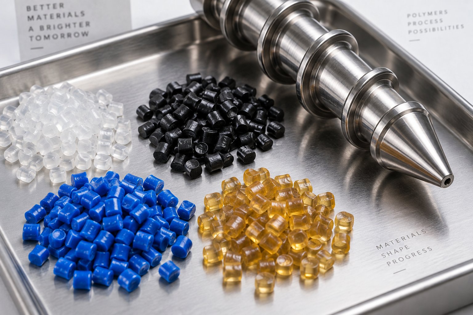
Knowing whether to use a single screw or a twin screw is a platform-level decision. The deeper, day-to-day challenge is this: you have a specific polymer sitting in your warehouse, and you need to know exactly which screw geometry will turn it into a clean, consistent melt. Compression ratio, L/D, screw type, and mixing elements all intersect differently for every resin family. Get the combination right, and you'll hit target output with minimal scrap. Miss by even one parameter, and you'll spend shifts chasing surging, gels, or degradation.
This section provides a direct polymer-to-screw mapping — the kind of practical reference that saves hours of trial-and-error on the production floor. Every recommendation below reflects industry-conventional guidance for virgin pellet feedstock on standard thermoplastic extruder platforms. Your specific grade, additive package, and throughput target may require fine-tuning, but these ranges give you a confident starting point.
Commodity Polymers — PE, PP, PS, and PVC Screw Requirements
Commodity resins account for the vast majority of extrusion volume worldwide, yet each one brings distinct screw design challenges that processors often underestimate.
Polyethylene (HDPE, LDPE, LLDPE) — PE grades are thermally forgiving, but their relatively low bulk density compared to melt density demands higher compression ratios in the 3.0:1 to 4.0:1 range. Here's the detail many guides miss: HDPE pellets and LLDPE pellets don't behave identically in the extruder feed barrel. HDPE pellets tend to be harder and more uniform, conveying predictably through friction against the barrel wall. LLDPE pellets, especially metallocene grades, are softer and "stickier," which can cause bridging in the feed throat and erratic solids conveying. For LLDPE blown-film lines, a grooved-feed barrel section paired with a barrier screw often solves both problems — the grooves ensure positive conveying while the barrier flight manages the melting progression. L/D ratios of 24:1 to 30:1 work well for most PE pipe and sheet applications, extending to 30:1–34:1 for high-output blown-film lines.
Polypropylene (PP) — PP shares many processing characteristics with PE, tolerating similar compression ratios of 3.0:1 to 4.0:1 and L/D ranges of 24:1 to 30:1. The distinction lies in mixing requirements. Nucleated PP grades — widely used for thermoformed packaging — need thorough distributive mixing to spread the nucleating agent uniformly, or you'll see inconsistent clarity and crystallization artifacts in the final product. Adding a Saxton or pineapple mixing section downstream of a barrier melting zone addresses this effectively. For glass-fiber-reinforced PP compounds, research on fiber-reinforced thermoplastics demonstrates that screw configuration has a measurable impact on fiber length retention — kneading blocks and high-shear elements shorten fibers significantly, so the screw must balance mixing intensity against mechanical property preservation.
Polystyrene (GPPS, HIPS) — PS is the commodity resin that punishes shear mistakes fastest. It has a relatively high bulk density, meaning less volumetric change from pellet to melt and a correspondingly lower compression ratio of 2.5:1 to 3.0:1. The real risk is shear sensitivity: excessive compression or aggressive mixing sections raise melt temperature rapidly, causing discoloration in GPPS and degradation of the rubber phase in HIPS — which directly reduces impact strength. A standard metering screw with moderate L/D (24:1 to 28:1) and gentle mixing elements handles PS well. Avoid barrier screws with tight clearances unless your throughput demands absolutely require them.
PVC (Rigid and Flexible) — PVC stands apart from every other commodity polymer because it degrades through dehydrochlorination — releasing corrosive hydrochloric acid gas — at temperatures only modestly above its processing range. This demands the lowest compression ratios in the commodity family, typically around 2.0:1, with L/D ratios kept short (18:1 to 24:1) to minimize residence time. The screw must generate just enough shear to fuse the PVC particles without pushing melt temperature beyond roughly 200 degrees Celsius. Rigid PVC pipe and profile lines overwhelmingly use counter-rotating twin-screw extruders for this reason, and the barrel liner must resist HCl corrosion. Flexible PVC with plasticizer is somewhat more tolerant but still requires conservative screw geometry compared to polyolefins.
Engineering Resins and High-Performance Polymers
Engineering resins bring higher melting points, tighter processing windows, and material-specific complications that commodity screw designs simply cannot handle.
PA (Nylon 6, Nylon 66) — Nylon's defining challenge is moisture. As a hygroscopic polymer, it absorbs atmospheric water rapidly, and even small amounts of residual moisture cause hydrolytic chain scission during processing — reducing molecular weight, mechanical strength, and surface quality. Two approaches address this: pre-drying the resin to below 0.1% moisture before feeding, or using a vented (two-stage) screw that removes moisture mid-barrel through vacuum devolatilization. Many production lines use both, with a venting screw configuration as insurance against incomplete drying. Compression ratios of 3.0:1 to 3.5:1 and L/D of 28:1 to 32:1 are typical, with the longer barrel providing space for the vent zone.
PC (Polycarbonate) — PC has one of the highest melt viscosities among engineering thermoplastics, requiring substantial shear energy to reach processable flow. At the same time, it is sensitive to hydrolytic degradation at elevated temperatures and long residence times. The screw must deliver adequate shear without overheating — a balancing act that favors compression ratios of 2.5:1 to 3.0:1 with barrier screw designs and carefully calibrated process controls for plastics extrusion. L/D of 26:1 to 30:1 is common. Moisture must be reduced below 0.02% before processing, or optical clarity and impact strength suffer dramatically.
POM (Acetal, Polyoxymethylene) — POM has one of the narrowest processing windows of any engineering resin. Push melt temperature even 10 to 15 degrees above the upper limit, and formaldehyde gas generation accelerates rapidly — a safety hazard and a direct cause of voids and surface defects. Screws for POM use moderate compression (2.5:1 to 3.5:1) with L/D of 20:1 to 24:1 to keep residence time short. Temperature uniformity across every barrel zone is critical; any hot spot becomes a potential degradation site.
PET (Polyethylene Terephthalate) — PET extrusion, particularly for sheet and film, revolves around preserving intrinsic viscosity (IV). Every percentage point of moisture above the target and every unnecessary second of residence time at melt temperature chips away at IV, reducing the mechanical properties that make PET valuable. Screws for PET typically feature compression ratios of 2.5:1 to 3.5:1 with L/D of 28:1 to 32:1. Vented screws are common for recycled PET (rPET) to handle residual moisture and contaminants. Careful thermal management through precise zone-by-zone barrel temperature control prevents localized overheating that accelerates acetaldehyde generation — a critical concern in food-packaging applications.
Challenging Processing Scenarios
Real-world extrusion rarely involves pristine virgin pellets running 24/7 on a dedicated line. Three scenarios challenge screw design beyond the textbook recommendations above.
Recycled and regrind materials — Post-consumer and post-industrial recyclate arrives with inconsistent bulk density, variable particle size, mixed contamination, and unknown moisture content. Flake regrind packs differently than uniform pellets, often feeding erratically into a standard-depth feed section. Deeper feed channels or grooved extruder feed barrel configurations improve conveying consistency. Compression ratios may need to shift downward slightly to avoid over-shearing already heat-degraded polymer chains. Vented screws are strongly recommended to handle unpredictable volatile content without pre-drying every batch.
Highly filled compounds — Glass fibers, mineral fillers (calcium carbonate, talc), and carbon fibers add rigidity and heat deflection performance but exact a toll on the screw. University research on glass-fiber-reinforced polypropylene compounding confirms that screw configurations with kneading blocks significantly shorten fiber length compared to conveying-only setups — the average fiber length decreased measurably with increasing fiber content across all configurations tested. This means the screw must disperse fillers effectively while minimizing unnecessary high-shear zones that destroy reinforcing fiber length. Compression ratios drop to 1.8:1 to 2.5:1 for highly filled systems because the fillers themselves generate shear heat, and the combined bulk density of polymer-plus-filler is higher than the neat resin. Equally important, abrasive fillers demand wear-resistant screw metallurgy — tungsten carbide coatings or bimetallic barrels — to maintain dimensional tolerances over the screw's service life.
Heat-sensitive bioplastics — PLA, PHA, and starch-based blends present a unique combination of challenges: low thermal stability, sensitivity to moisture, and narrow processing windows comparable to PVC. Low-compression screws (2.0:1 to 2.5:1) with moderate L/D (24:1 to 28:1) keep shear heat in check. Twin-screw compounding, when needed for filler dispersion in biocomposite applications, benefits from conveying-dominant screw configurations that minimize aggressive kneading elements.
The comprehensive mapping table below pulls every recommendation into a single reference. Treat these ranges as proven starting points — your specific grade, additive package, and throughput target may push you toward one end of each range or the other.
| Polymer | Recommended Compression Ratio Range | Preferred L/D Range | Screw Type | Special Considerations |
|---|---|---|---|---|
| HDPE | 3.0:1 – 4.0:1 | 24:1 – 30:1 | Barrier (Barr type) with Maddock mixer | Grooved-feed barrel for high-output blown film; thermally tolerant |
| LLDPE | 3.0:1 – 3.5:1 | 24:1 – 34:1 | Barrier with distributive mixer | Soft pellets may bridge in feed throat; grooved-feed barrel recommended |
| LDPE | 3.0:1 – 4.0:1 | 24:1 – 30:1 | Barrier or general-purpose metering | Low melt viscosity; moderate mixing demands |
| PP (Homo/Copolymer) | 3.0:1 – 4.0:1 | 24:1 – 30:1 | Barrier with Saxton or pineapple mixer | Nucleated grades need strong distributive mixing for clarity |
| GPPS | 2.5:1 – 3.0:1 | 24:1 – 28:1 | General-purpose metering | Shear-sensitive; avoid aggressive mixing elements |
| HIPS | 2.5:1 – 3.0:1 | 24:1 – 28:1 | General-purpose metering with gentle mixer | Excessive shear degrades rubber phase and reduces impact strength |
| ABS | 2.5:1 – 3.0:1 | 24:1 – 30:1 | Barrier or general-purpose with mixer | Butadiene phase sensitive to high shear and prolonged heat exposure |
| Rigid PVC | 2.0:1 – 2.5:1 | 18:1 – 24:1 | Counter-rotating twin screw (low shear) | HCl-resistant barrel liner required; minimize residence time |
| Flexible PVC | 2.0:1 – 2.5:1 | 20:1 – 24:1 | Single screw, low compression | Plasticizer absorption aids fusion; still heat-sensitive |
| PA (Nylon 6, 66) | 3.0:1 – 3.5:1 | 28:1 – 32:1 | Vented (two-stage) with barrier zone | Hygroscopic; pre-dry and/or use vacuum vent for moisture removal |
| PC (Polycarbonate) | 2.5:1 – 3.0:1 | 26:1 – 30:1 | Barrier with moderate mixing section | High melt viscosity; moisture must be below 0.02%; avoid prolonged residence |
| POM (Acetal) | 2.5:1 – 3.5:1 | 20:1 – 24:1 | General-purpose metering | Narrow processing window; formaldehyde risk above safe melt temperature |
| PET | 2.5:1 – 3.5:1 | 28:1 – 32:1 | Vented screw or pre-dried feed | IV preservation critical; minimize shear and residence time for food-grade |
| Recycled / Regrind | 2.5:1 – 3.5:1 (varies by base resin) | 26:1 – 32:1 | Vented screw with deeper feed section | Inconsistent bulk density and moisture; grooved-feed barrel improves conveying |
| Glass-Fiber-Filled Compounds | 1.8:1 – 2.5:1 | 28:1 – 36:1 | Conveying-dominant twin screw or barrier single screw | Minimize kneading to preserve fiber length; wear-resistant screw metallurgy essential |
| Mineral-Filled Compounds | 2.0:1 – 2.5:1 | 28:1 – 34:1 | Twin screw with dispersive mixing | Abrasive — requires carbide-coated screw and bimetallic barrel |
| PLA / Bioplastics | 2.0:1 – 2.5:1 | 24:1 – 28:1 | Low-shear single screw or gentle twin screw | Moisture-sensitive and heat-sensitive; dry thoroughly before processing |
One pattern worth internalizing: heat-sensitive materials (PVC, POM, PLA) cluster in the low-compression, short-L/D corner of the table, while thermally robust polyolefins tolerate higher compression and longer barrels. Engineering resins occupy a middle ground, with moisture management — whether through pre-drying, vented screws, or both — being the recurring theme.
Matching the screw to your polymer is critical, but the screw does not operate in isolation. It spins inside a barrel, under extreme pressure, against abrasive or corrosive melts, for thousands of hours. How long those carefully chosen flight geometries maintain their critical dimensions depends entirely on what is protecting the screw's surface — the coatings and treatments that separate a screw lasting six months from one lasting six years.
Screw and Barrel Coatings That Extend Service Life
A perfectly specified screw geometry means nothing if the flight dimensions erode after a few thousand hours of operation. Every time the screw rotates, its flight tips drag against the barrel wall under enormous pressure while conveying polymer melts that may contain abrasive glass fibers, corrosive acid byproducts, or both simultaneously. The original clearance between flight crest and barrel bore — often just 0.001 inch per side per inch of diameter — is the dimension that keeps leakage flow low, shear rates consistent, and output stable. Once wear opens that gap, melting efficiency declines, output drops at constant RPM, and melt quality deteriorates in ways no process adjustment can fully recover.
Surface treatments are the insurance policy that keeps those critical tolerances intact. Choosing the right one depends on what your screw is up against — and the threats fall into three distinct categories that often overlap in practice.
Why Screw Surface Treatment Matters for Longevity
Think of a plastic extrusion screw as operating inside a triple-threat environment. First, there is abrasive wear — the most common damage mechanism. As pellets compact against the barrel wall and fillers shear across flight surfaces, hard particles gradually remove material from softer surfaces. Glass-fiber-reinforced compounds, mineral-filled masterbatches, and even contaminant-laden regrind accelerate this erosion dramatically. Some aggressive fillers can cut screw and barrel useful life by 50% or more.
Second, there is corrosive wear. PVC releases hydrochloric acid during processing. Fluoropolymers emit hydrofluoric acid. Acetal resins generate formic acid. These corrosive byproducts attack metal components with a high iron matrix, pitting the screw surface and weakening it structurally so that mechanical wear can finish the job faster.
Third, there is adhesive wear — metal-to-metal contact between the screw flight and barrel wall. When deflection, misalignment, or solids wedging forces the screw against the bore, extremely high stresses cause the surfaces to briefly weld together and then fracture, leaving scoring, galling, and burrs on both the screw and the barrel.
No single surface treatment defeats all three threats equally. The goal is to match the treatment to the dominant wear mechanism in your specific application — and to select compatible treatments for both the screw and the barrel lining so that the harder component does not accelerate wear on the softer one.
Comparing Nitriding, Chrome Plating, and Advanced Coatings
The range of available surface treatments spans from cost-effective baseline hardening to premium coatings engineered for the most demanding extrusion barrels and screws. Here is how the major options compare across the properties that matter most on the production floor.
| Treatment Type | Hardness Range | Corrosion Resistance | Abrasion Resistance | Cost Level | Best For |
|---|---|---|---|---|---|
| Gas Nitriding | ~55–65 HRC equivalent on standard steels (4140, 4340); exceeding 70 HRC equivalent on specialty grades like H-13 and Nit135M | Moderate — chromium nitrides in the case layer provide some chemical resistance, but limited against strong acids | Good — hardened case resists mild to moderate abrasion from unfilled and lightly filled polymers | Low to moderate | Unfilled polyolefins, PS, ABS, and general-purpose extrusion with non-corrosive resins |
| Ion/Plasma Nitriding | Same hardness potential as gas nitriding; selective masking allows treatment of specific zones only | Moderate — similar to gas nitriding; thermally stable CrN layers endure elevated processing temperatures | Good to very good — especially on nitridable steels (H-13, Nit135M, CPM9V) | Moderate | Long extrusion barrels and screws where selective hardening is needed; demanding abrasion applications on specialty steels |
| Hard Chrome Plating | ~65–70 HRC | Good against many melt byproducts; provides a barrier layer over the base steel | Moderate — chrome layer is hard but relatively thin and can chip or exfoliate under thermal cycling | Moderate | Corrosion protection for mildly corrosive polymers; applications where surface finish and release properties matter |
| Cobalt-Based Weld Overlays (Stellite) | ~38–55 HRC depending on grade | Very good — cobalt matrix resists chemical attack effectively | Good — carbides in the matrix resist moderate abrasion | Moderate to high | Flight-tip hardfacing on screws processing moderately abrasive or corrosive compounds |
| Nickel-Based Weld Overlays (Colmonoy) | ~40–62 HRC depending on grade (Colmonoy 56 to Colmonoy 83) | Excellent — nickel-rich matrix with boride and carbide phases resists acid attack from PVC, acetal, and fluoropolymer byproducts | Good to very good — higher grades (Colmonoy 83) offer stronger wear resistance | Moderate to high | PVC extrusion, fluoropolymer processing, and applications combining corrosion and wear challenges |
| Tungsten Carbide Coatings | ~70+ HRC equivalent | Variable — depends on binder matrix; some grades offer limited corrosion resistance | Excellent — among the hardest commercially available screw coatings | High | Glass-fiber-reinforced compounds, mineral-filled masterbatch, and any application where abrasion is the primary life-limiting factor |
| Nickel-Boron Alloy Linings | ~55–65 HRC | Excellent — nickel-rich alloy with molybdenum, boride, and carbide bases resists strong acid environments | Very good — carbide phases provide solid abrasion protection alongside corrosion resistance | High | Bimetallic extrusion barrels for PVC, fluoropolymers, and chemically aggressive compounds requiring dual protection |
A few details from the table deserve closer attention. Ion/plasma nitriding stands out for long screws because the process runs in vertical vacuum chambers — Advanced Heat Treat Corp. operates vessels capable of processing screws over 40 feet (12 meters) long. Gas nitriding works well for shorter screws but becomes impractical at extreme lengths. The nitrided layers contain chromium nitrides (CrN) that remain thermally stable at the elevated temperatures used in extrusion, ensuring the hardness case does not soften during production.
Hard chrome plating, while offering good corrosion protection, comes with a caveat: its coefficient of thermal expansion differs from the underlying steel. At elevated barrel temperatures, this mismatch can cause the chrome layer to exfoliate from the surface, particularly on long screws that experience significant thermal gradients along their length. For this reason, chrome plating is most reliable on shorter components or in applications with moderate and stable temperature profiles.
Weld overlays like Stellite and Colmonoy provide excellent mechanical and anti-corrosive properties, but they bond mechanically rather than metallurgically to the base screw material. Adherence to the base material is comparatively weaker than diffusion-based treatments like nitriding, meaning delamination under severe impact or thermal shock is a real risk — especially if the overlay was not applied with proper pre-heat and post-weld procedures.
Matching Surface Treatment to Processing Conditions
With this many options available, how do you choose? Start by identifying the dominant wear mechanism for your application, then select the treatment that addresses that threat while remaining compatible with your barrel lining material. Running a hard screw coating against a softer barrel liner — or vice versa — creates a mismatch that accelerates wear on the softer component.
Use this quick-reference checklist to match your processing conditions to the right surface treatment:
- Unfilled polyolefins (PE, PP) and styrenics (PS, ABS) — Gas or ion/plasma nitriding on a 4140 or 4340 steel screw provides cost-effective protection. Abrasion is minimal, corrosion is negligible, and the hardened case easily outlasts the intervals between scheduled maintenance.
- Glass-fiber-reinforced compounds (PA-GF, PP-GF, PBT-GF) — Tungsten carbide coatings on flight tips, combined with a bimetallic barrel liner containing high tungsten carbide content. Abrasion is the dominant threat, and standard nitriding will not survive the erosive force of 30–50% glass-fiber loading.
- Mineral-filled compounds (CaCO3, talc, BaSO4) — Tungsten carbide or high-hardness weld overlays on the screw, paired with a wear-resistant bimetallic barrel. Mineral fillers generate less aggressive point-contact abrasion than glass fibers but sustain steady erosion over time.
- PVC (rigid and flexible) — Nickel-based alloys (Colmonoy family) on the screw surface, with a nickel-boron alloy bimetallic barrel lining. Corrosion from HCl is the primary threat; standard nitrided steel or plain chrome plating will deteriorate rapidly under sustained acid exposure.
- Fluoropolymers (PTFE, FEP, PFA) — The most chemically aggressive environment in extrusion. Nickel-rich bimetallic barrel linings and nickel-based screw coatings (Colmonoy 83 or equivalent) are essential. Hydrofluoric acid emitted during processing causes rapid corrosion of any component with a high iron matrix. Thermal expansion matching between screw and barrel materials is also critical to prevent seizing.
- Recycled feedstock with unknown contamination — A pragmatic middle ground: ion/plasma nitrided screws on a nitridable steel (H-13 or CPM9V for maximum hardness) paired with a general wear-resistant bimetallic barrel. This combination handles the unpredictable mix of abrasive contaminants and mild corrosives typical of post-consumer regrind streams.
- Multi-material or frequent-changeover operations — Prioritize surface finish and release properties. A polished, chrome-plated or nitrided screw with a smooth surface reduces material adhesion and speeds purging during color or resin changes.
One final principle ties this entire discussion together: surface treatment is not a standalone decision. It must be considered alongside the screw's base material, the barrel lining alloy, and the clearance tolerances specified for the application. A screw and barrel pair manufactured from compatible, application-matched alloys — and maintained with regular clearance checks — will consistently outperform a premium-coated screw running inside a worn or mismatched barrel.
Surface treatment keeps the screw's geometry intact over time. But even the best coating cannot compensate for a screw that was never properly integrated into the rest of the extrusion line — the barrel temperature profile, the die resistance, the screen pack, and the feeding system all interact with screw performance in ways that determine whether your carefully specified design delivers on its promise or falls short.
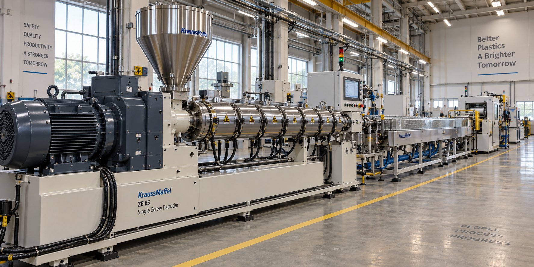
System Integration, Wear Diagnosis, and Sourcing the Right Extrusion Screw Barrel
A screw does not operate in a vacuum. It spins inside a barrel surrounded by independently controlled heating and cooling zones, pushes melt through a screen pack and breaker plate, and builds pressure against a die whose resistance shapes every dimension of the final product. Treat the screw as an isolated component — ignoring how it interacts with these surrounding systems — and even the most precisely engineered geometry will underperform. The most experienced processors know this instinctively: the extrusion screw barrel assembly is a system, and every element in that system either supports or undermines the screw's ability to deliver consistent melt.
How Screw Design Interacts with Barrel, Die, and Downstream Components
Imagine you have installed a perfectly matched barrier screw for your HDPE pipe line. Compression ratio, L/D, mixing section — everything checks out on paper. Yet output surges erratically, melt temperature runs hotter than expected, and the product shows intermittent wall-thickness variation. Where do you look?
Start with the barrel temperature profile. A typical single-screw extruder uses four to eight independently controlled zones, each contributing to a cumulative melt-temperature fingerprint. If Zone 3 runs too hot because a heater band is partially shorted, it overheats the polymer locally and disrupts the solid-bed progression in the transition zone — exactly where the barrier flight depends on a controlled, progressive melt boundary. The screw design assumed a specific heat input from the barrel; a faulty zone sabotages that assumption.
Next, consider die resistance and back pressure. The metering zone builds pressure to push melt through the screen pack, breaker plate, and die land. Increase screen pack mesh density — say, from 40/60/40 to 80/150/80 for better gel filtration — and the back pressure rises. That added resistance changes the pressure-flow balance across the metering zone, reducing throughput at any given RPM and increasing melt temperature through additional viscous heating. If the die land is partially blocked by plate-out buildup, the effect is the same: more back pressure, more shear heat, less output stability.
Feeding consistency ties into this chain as well. A flood-fed hopper that bridges intermittently starves the feed zone, creating pressure pulses that travel through the screw and emerge as output variation at the die. Grooved-feed barrels, gravimetric feeders, and consistent pellet geometry all work to keep the screw's intake steady — and when they fail, the screw gets blamed for problems that originated upstream.
The practical takeaway is straightforward: when troubleshooting an extrusion line, never evaluate the screw in isolation. Check zone-by-zone barrel temperatures for drift, measure melt pressure at the adapter for stability, verify screen pack condition, and confirm consistent feed supply before concluding the screw itself is the problem.
Recognizing When Your Screw Barrel Needs Replacement
Every hour of operation removes a few microns of material from the flight tips, the root diameter, and the barrel bore. This wear is inevitable — the question is how fast it progresses and when it becomes unacceptable. Extrusion experts Timothy Womer and Mark Spalding emphasize that the main signs of wear include a reduction in specific rate (output per RPM) and higher discharge temperatures. As the flight clearance opens, more melt leaks backward over the flights, forcing the operator to increase screw speed to maintain throughput — which in turn generates additional shear heat and accelerates further wear.
A practical guideline for new-screw clearance: the radial gap per side is typically the nominal screw diameter divided by 1,000. A 3.5-inch screw, for example, starts life with approximately 0.004 inches of clearance per side. As that gap doubles or triples, pumping efficiency drops measurably.
Use this checklist to identify when replacement is overdue:
- Declining output at constant RPM — If you must increase screw speed by more than 10-15% to maintain the same throughput, clearance wear is likely the cause. Predictive maintenance data shows that output below 85% of rated capacity at rated RPM signals the screw has reached the replacement threshold.
- Rising discharge temperature — Melt temperature climbing 8-15 degrees Fahrenheit above its historical baseline at the same operating conditions points to increased leakage flow and reduced heat-transfer efficiency at the barrel wall.
- Increasing motor amperage — A worn screw forces the drive motor to work harder to achieve the same output, drawing measurably higher current. An increase exceeding 10% above baseline warrants investigation.
- Visible flight-tip wear — During a scheduled screw pull, measure the outside diameter of the flights at multiple points. If the hard facing (typically about 0.060 inches thick on a new screw) is completely worn through, performance will be extremely poor, especially on smaller-diameter extruders.
- Deteriorating part quality — Gels, unmelts, black specks, and dimensional variation in the extrudate are downstream symptoms of upstream clearance problems. If adjusting barrel temperatures and screen packs does not resolve these defects, the screw-barrel fit has likely degraded beyond the acceptable window.
- Surging or melt-pressure instability — Cyclic pressure fluctuations exceeding +/-50 PSI during steady-state operation suggest the metering zone can no longer maintain consistent pumping due to excessive back-leakage over worn flights.
One important note from Womer and Spalding: a screw should never be refurbished more than three times, because repeated welding of new hard facing onto the base material deteriorates the substrate and increases the risk of delamination. When the screw is pulled, always measure the barrel bore as well — an iron-based bimetallic barrel liner typically lasts about three times the service life of the screw, but confirming this with actual measurements prevents premature failure of a new screw installed into a worn barrel.
Keep a spare screw in storage so that when the current one reaches end-of-life, you can swap it during a planned shutdown rather than waiting for a catastrophic failure. That single practice — having a qualified replacement ready — transforms an emergency repair into a routine maintenance event.
Sourcing Custom and Replacement Screw Barrels
Whether you are replacing a worn screw on a Davis-Standard extruder, upgrading the barrel on a legacy line, or specifying a new extrusion screw barrel for a greenfield installation, the supplier you choose has a direct impact on how long the new components maintain their performance. A replacement that matches basic dimensions but falls short on metallurgy, heat treatment, or clearance tolerances will wear prematurely and put you right back in the same replacement cycle.
Here is what to evaluate before committing to a screw barrel supplier:
- Material certifications and steel grades — A credible supplier should name the specific alloy used for the screw shaft (e.g., 38CrMoAlA, 4140, or H-13), the nitriding or coating process applied, and the resulting hardness range. Vague descriptions like "high-quality steel" without supporting data are a red flag. For bimetallic barrels, ask for the alloy composition of the liner, its hardness (typically HRC 58-65 for demanding applications), and the alloy depth.
- Ability to match OEM specifications — Whether the original equipment came from a Davis Standard extruder platform or another manufacturer, the replacement screw must replicate critical dimensions: flight OD, root diameters in each zone, flight clearance tolerance, channel depths, and overall L/D. A supplier with reverse-engineering capability and in-house metrology can measure a worn screw, identify the original design intent, and manufacture to those specifications — or improve on them if the original design was suboptimal for your current material.
- Range of application-specific designs — Extrusion lines are diverse. A supplier worth partnering with should cover pipe, blown film, cast sheet, pelletizing, recycling, and general-purpose configurations rather than offering a single generic geometry for every application. NANHAIYA, for example, provides custom and replacement single screw barrels across all of these application categories — the kind of breadth that lets you consolidate sourcing and maintain consistent quality across different production lines.
- Engineering support and customization — If your process has shifted — new resin grade, higher filler loading, increased output target — a supplier with engineering staff can recommend screw geometry modifications rather than simply duplicating the old design. This capability separates a manufacturing partner from a parts vendor.
- Turnaround time and inventory strategy — Unplanned downtime on an extrusion line costs thousands of dollars per day. A supplier that can deliver a replacement extrusion screw barrel within days rather than weeks keeps your spare-parts strategy viable. Ask about lead times for both standard and custom orders, and confirm whether pre-shipment inspection is included in the process.
The feed screw barrel market is projected to reach USD 3.33 billion by 2034, reflecting how strategic this procurement decision has become as processors push toward tougher materials, higher throughputs, and tighter quality demands. Treating screw barrel sourcing as a long-term partnership — rather than a one-off transaction — pays dividends in consistent part quality, reduced qualification work, and predictable maintenance scheduling.
Ultimately, the plastic extrusion screw is only as good as the system surrounding it: the barrel that heats and houses it, the coatings that protect it, the die that resists it, and the supplier that builds and replaces it when the time comes. Approach each of these elements with the same rigor you apply to screw geometry and polymer selection, and your extrusion line will reward you with the output quality, throughput, and uptime that every processor is chasing.
Frequently Asked Questions About Plastic Extrusion Screws
1. What are the three zones of a plastic extrusion screw?
A plastic extrusion screw consists of the feed zone, transition (compression) zone, and metering zone. The feed zone has deep, constant-depth channels that accept solid pellets from the hopper. The transition zone features a gradually decreasing channel depth that compacts softening pellets, squeezes out trapped air, and accelerates melting through barrel-wall contact and shear friction. The metering zone has a shallow, constant-depth channel that applies precise shear and pressure to deliver a uniform, fully molten stream to the die at a steady flow rate.
2. How do I choose the right L/D ratio for my extrusion screw?
长径比 (L/D) 的选择主要取决于聚合物类型和加工目标。热敏性 PVC 通常使用 18:1 至 24:1 的长径比,以最大程度地减少热暴露。通用聚烯烃挤出机在 24:1 至 30:1 的长径比下效果良好,而尼龙和聚碳酸酯等工程树脂通常需要 28:1 至 32:1 的长径比,以满足排气区和更高熔点的要求。同向旋转双螺杆混炼生产线的长径比可达 36:1 至 60:1,以实现深度混合和脱挥发分。关键的权衡在于,较长的长径比可以提高熔体均匀性,但会增加能耗、设备成本以及热敏性材料的降解风险。
3. 聚乙烯和聚氯乙烯的压缩比应该分别是多少?
聚乙烯(HDPE、LDPE、LLDPE)需要3.0:1至4.0:1的压缩比,因为其颗粒堆积密度远低于熔体密度,螺杆必须压缩掉更多的空气体积。相比之下,聚氯乙烯(PVC)只需要2.0:1至2.5:1的压缩比,因为它对热极其敏感,如果受到过大的剪切力,会因脱氯化氢而降解。指导原则是,压缩比应接近固体堆积密度与熔体密度的比值,同时保持在聚合物的热耐受范围内。
4. 我应该何时更换挤出机螺杆和料筒?
关键更换指标包括:在恒定转速下产量下降超过 15%;出料熔体温度比历史基准值升高 8 至 15 华氏度;电机电流增加超过 10%;螺杆拉拔过程中可见螺纹尖端磨损;以及持续存在的零件质量缺陷,例如凝胶、未熔化或尺寸偏差,且无法通过调整料筒温度来解决。在稳态运行期间,熔体压力波动超过正负 50 PSI 也表明螺纹间隙过大。专家建议螺杆翻新次数不应超过三次,并且在安装新螺杆时务必测量料筒内径以确认兼容性。
5. 哪些螺杆涂层最适合玻璃纤维填充化合物?
玻璃纤维增强复合材料的螺杆叶片尖端需要碳化钨涂层,因为玻璃纤维具有极强的磨蚀性,会迅速侵蚀标准的氮化表面。为了最大限度地延长使用寿命,应将碳化钨涂层螺杆与高碳化钨含量的双金属筒体衬套配合使用。对于纤维含量超过 15% 至 20% 的情况,标准的气体氮化处理已不足以满足要求。对于玻璃纤维与腐蚀性聚合物基体结合的复合材料,镍基合金(例如 Colmonoy 牌号)涂层可在耐磨性和耐腐蚀性之间取得平衡,但就纯粹的耐磨保护而言,碳化钨仍然是最佳选择。
Written by
Nanhaiya Technical Team
Zhoushan Nanhaiya Plastic Machinery Co., Ltd.
The Nanhaiya technical team supports screw and barrel manufacturing projects through application review, technical communication, custom manufacturing coordination, and production and quality control.
Discuss Your Application
Related Articles
More insights on screw barrel technology and plastics processing.

What Nobody Tells You About Screw Barrel For Plastic Machine Design
Oct 10, 2026
Learn how screw barrel for plastic machine design affects melt quality, throughput, and wear life. Covers geometry, resin matching, troubleshooting, and sourcing.
Read Article
Single Screw Extruder for Sheet: Stop Guessing, Start Specifying
Oct 9, 2026
Learn how to specify a single screw extruder for sheet production. Covers screw geometry, resin-specific processing, troubleshooting, and maintenance best practices.
Read Article
PE Pipe Extruder Machine: What Datasheets Won't Tell You
Oct 9, 2026
Learn how a PE pipe extruder machine works, key specs explained, material grade selection, maintenance tips, and buyer guidance beyond the datasheet.
Read ArticleLooking for something else?
Search by material, symptom or product and jump straight to the relevant page.
These are navigation suggestions based on keyword matching — not a quotation, not a delivery commitment, and not a substitute for engineering review. Final specification is confirmed by our engineers against your drawings and processed material.
Need help with screw barrel selection?
Share your machine model, processed material and application. Our team can help with pricing and technical support.