

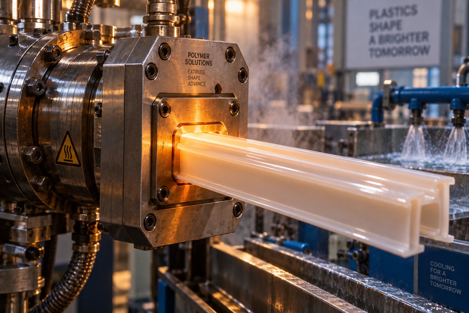
Understanding Plastic Extrusion Defects and Why They Happen
Imagine running your extrusion line at full speed, only to discover that the last hour of output is destined for the scrap bin. Rough surfaces, warped profiles, mysterious bubbles - something went wrong, but where? The answer almost always hides somewhere along the full length of the production line, and finding it starts with understanding exactly what you are dealing with.
A plastic extrusion defect is any deviation in shape, surface quality, dimensional accuracy, or material integrity that occurs during the extrusion process. These flaws can originate upstream during material preparation and feeding, inside the extruder at the barrel, screw, or die, or downstream in calibration, cooling, haul-off, and cutting stations. Because every station on the line influences the final product, effective troubleshooting demands a whole-system perspective rather than a narrow focus on one variable at a time.
The diagnostic philosophy behind this guide is simple: start with what you see on the production floor, then trace backward to the root cause. As practical troubleshooting frameworks emphasize, naming the visible defect and locating where it first appears are the two fastest steps toward a real fix - far more effective than adjusting barrel temperatures or screw speed blindly.
What Are Plastic Extrusion Defects
Defects in plastic extrusions fall into four broad categories. Surface imperfections include melt fracture, sharkskin texture, die lines, and rough finishes that compromise appearance and function. Dimensional inaccuracies show up as wall thickness variation, ovality, or profiles that drift out of spec. Structural weaknesses - voids, sink marks, and internal cracks - threaten mechanical performance even when the outside looks acceptable. Finally, aesthetic flaws such as color streaks, discoloration, and splay marks lead to customer rejections that no amount of rework can easily recover.
Why Defect Identification Matters for Production Efficiency
Every undetected defect triggers a chain of costly consequences. Scrap rates climb, rework ties up labor and machine time, customer rejections erode trust, and unplanned line stoppages disrupt delivery schedules. A statistical study of extrusion product defects reinforces the point that defect analysis is integral to improving productivity, efficiency, and quality in any extrusion environment. The sooner a flaw is identified and traced to its source, the less damage it does to the bottom line.
This guide walks through every major defect family so you can match what you see to why it happened:
- Surface defects - melt fracture, sharkskin, die lines, and rough finish
- Dimensional and structural defects - warping, voids, sink marks, and output instability
- Color defects - streaking, thermal discoloration, and pigment dispersion failures
- Moisture-related defects - splay marks, foaming, and hydrolytic degradation
- Extrusion-type-specific defects - failure modes unique to blown film, pipe, profile, and co-extrusion lines
- Screw-design-driven defects - how compression ratio, metering zone length, and mixing elements shape melt quality
Each section follows the same pattern: visual identification, root cause analysis, and corrective direction. The goal is to give operators and engineers a reliable path from symptom to solution - starting with the defects that show up most often on the surface of the extrudate itself.
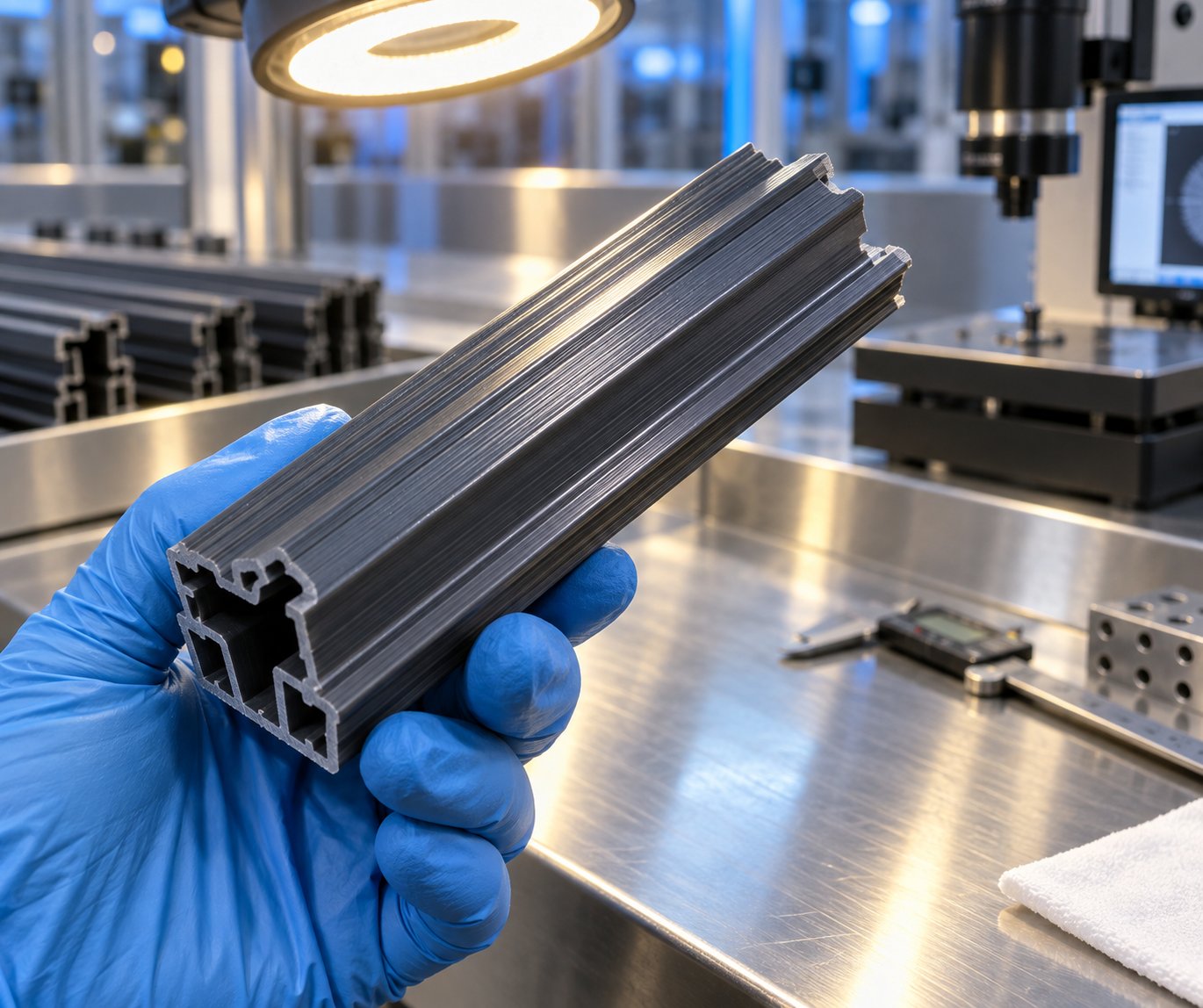
Surface Defects From Melt Fracture to Die Lines
Pick up an extruded plastic part fresh off the line and run your fingers across it. If it feels rough, ridged, or streaked instead of smooth and glossy, you are looking at a surface defect - and the fix depends entirely on which type you are dealing with. Surface flaws are the most immediately visible category of extrusion problems, and they are also among the most common reasons for rejected product. The good news? Each one leaves a distinct visual fingerprint that points back to a specific set of process variables.
Melt Fracture and Sharkskin Explained
These two terms often get used interchangeably on the shop floor, but they describe related yet distinct phenomena. Understanding the difference matters because the severity - and the corrective response - are not the same.
Sharkskin appears as a fine, regular roughness on the extrudate surface, sometimes described as a matte or frosty texture. Look closely and you will see tiny ridges running perpendicular to the flow direction. Research published in the Journal of Non-Newtonian Fluid Mechanics confirms that this sharkskin extrusion defect originates right at the die exit, where polymer chains undergo rapid elongational stress as the velocity profile reorganizes from pressurized flow inside the die to free-surface flow outside it. At the earliest stage, the defect is so subtle that operators may only notice a loss of surface gloss - the crack amplitude can be as small as the wavelength of visible light, around 0.4 to 0.8 micrometers. As flow rate increases, the cracks deepen and become more organized.
The molecular weight distribution and melt elasticity of the polymer play a central role. Polymers with high molecular weight and narrow molecular weight distribution tend to develop sharkskin at lower output rates because their long chains resist the rapid stretching at the die lip. The critical stress for sharkskin onset is governed by the polymer's plateau modulus, weight-average molecular weight, and molecular mass between entanglements.
Gross melt fracture is far more dramatic. Instead of fine surface roughness, you will see severe, irregular distortion - the extrudate may look wavy, spiraled, or completely torn apart. This happens when polymer chains exceed the critical shear stress deeper inside the die channel, not just at the exit. Think of it this way: the polymer is being pushed through the die faster than its molecular structure can relax and flow smoothly. The result is a chaotic, unstable melt front that produces extruded plastic with visibly deformed geometry.
The corrective approach for both defects targets the same underlying principle - reduce the shear stress the polymer experiences at and near the die exit:
- Raise die zone temperature in small increments (3-5 degrees Celsius at a time) to lower melt viscosity and reduce the stress on polymer chains as they exit
- Reduce screw speed to decrease the volumetric flow rate, which directly lowers the shear rate through the die
- Increase die land length where equipment allows, giving the melt more time to relax stress before reaching the exit
- Evaluate the resin - switching to a grade with broader molecular weight distribution can shift the sharkskin onset to higher output rates
Die Lines and Surface Roughness
Die lines look very different from melt fracture. They appear as continuous streaks running in the machine direction - parallel to the flow, not perpendicular. A critical distinction is that true die lines have a fixed location along the transverse profile. If you mark a line on the sheet or film, it stays in the same cross-directional position run after run. Flow lines, by contrast, come and go, change positions, and vary in intensity. Extrusion die experts emphasize that correctly identifying which type of line you have is the essential first step, because the causes - and the fixes - diverge sharply.
True die lines stem from physical issues at the die lip or flow surfaces:
- Plate-out buildup - degraded polymer, additive residue, or filler deposits accumulate on the die lip and score the melt as it exits. Cleaning methods range from scraping with a brass shim to running purge compound at varied screw speeds. If buildup persists, raising die temperature set points can prevent polymer from stagnating and depositing on channel walls.
- Die lip damage - nicks, scratches, or corrosion on the die land or lip edges physically imprint onto every meter of extrudate. The remedy is professional repolishing of the flow surfaces and resharpening of the lip edges.
- Incorrect die gap - a gap that is too tight increases shear stress at the lip, amplifying any minor surface irregularity into a visible line.
Flow lines point to upstream issues rather than die damage:
- Inadequate mixing in the melt delivery system - reducing the die gap or using finer mesh screens can increase back pressure and improve melt homogeneity
- Unmelted polymer particles passing through the die - raising melt and die temperature set points helps ensure complete fusion
- Excess moisture in the feedstock, which creates localized surface disruptions as steam escapes the melt
A regular die cleaning schedule combined with careful inspection of flow surfaces after each split-and-clean procedure prevents the majority of persistent die lines. When lines reappear quickly after cleaning, the investigation should shift upstream to mixing quality and material condition.
Process Parameter Adjustments for Surface Quality
Every surface defect responds to a specific combination of process adjustments. The challenge is knowing which direction to move each variable - and understanding that changing one parameter inevitably affects others. The table below maps each common surface flaw to the key process levers and the directional change most likely to improve quality.
| Surface Defect | Barrel Zone Temps | Die Temperature | Screw Speed | Back Pressure | Additional Action |
|---|---|---|---|---|---|
| Sharkskin | Increase rear/mid zones slightly (+3-5 °C) | Increase (+5-10 °C) | Decrease moderately | No direct effect | Consider broader MWD resin; increase die land length |
| Gross Melt Fracture | Increase progressively across all zones (+5-10 °C) | Increase (+5-15 °C) | Decrease significantly | Monitor - may need reduction | Widen die gap if possible; evaluate die geometry |
| Die Lines (buildup) | No change needed | Increase slightly to reduce stagnation | Vary during purge cycle | No direct effect | Clean die lips; run purge compound; repolish if damaged |
| Die Lines (damage) | No change needed | No change needed | No change needed | No change needed | Professional die repolish and lip resharpening required |
| Flow Lines | Increase metering zone (+5-10 °C) | Increase (+5-10 °C) | Adjust to improve mixing | Increase to improve melt homogeneity | Check moisture content; use finer screen mesh |
| General Surface Roughness | Increase gradually across zones (+3-5 °C per step) | Increase (+5 °C) | Decrease if shear-related | Increase for better melt consolidation | Verify feedstock dryness; inspect screw wear |
Keep in mind that these are directional guidelines, not absolute prescriptions. A temperature increase that eliminates sharkskin on one resin may push a more thermally sensitive polymer toward degradation. Always make adjustments incrementally - a single variable at a time, in small steps - and allow the process to stabilize before evaluating the result. This disciplined approach becomes even more critical when dealing with defects that involve internal structure and dimensions, where multiple interacting variables can compound a problem far beyond what surface-level fixes can address.
Dimensional and Structural Defects in Extruded Products
A surface that looks flawless can still hide problems beneath it. Dimensional and structural defects are the ones that slip past a visual check - profiles that bow after leaving the line, walls that measure thick on one side and thin on the other, or voids buried deep inside a cross-section that only reveal themselves during downstream testing or, worse, in the field. These flaws are trickier to diagnose than surface imperfections because they rarely point to a single cause. Instead, they emerge from the interplay of temperature, pressure, melt viscosity, cooling rate, and mechanical tension acting on the extrudate simultaneously.
Warping and Dimensional Instability
You pull a finished profile off the cooling conveyor and lay it on a flat table. It rocks. One end curves upward, or the entire length bows to one side. That is warping, and it is one of the most frustrating extrusion warping causes to chase down because the distortion often does not appear until minutes or even hours after the product leaves the line.
The root cause is almost always an asymmetry in how the extruded plastics cool. When one side of a profile solidifies faster than the other, the slower-cooling side continues to shrink after the faster side has already locked into shape. The result is residual stress that releases as a curve or twist once the part is free from the haul-off grip. Semi-crystalline resins like polyethylene and polypropylene are especially sensitive to cooling rate because crystallization behavior amplifies the stress differential - amorphous materials like polystyrene are more forgiving in this regard.
Several downstream factors drive this cooling imbalance:
- Calibration sleeve misalignment - if the vacuum calibration sleeve is not concentric with the die exit, the melt contacts one wall of the sleeve before the other, creating uneven heat extraction from the start
- Cooling bath temperature gradients - water temperature that varies from one end of the tank to the other, or spray nozzles that deliver uneven coverage, produces differential cooling across the profile cross-section
- Haul-off speed mismatch - running the puller too fast relative to the extruder output stretches the still-soft melt unevenly, locking in orientation stress that manifests as warping after the part relaxes
- Insufficient cooling length - if the cooling conveyor is too short for the line speed being run, the profile has not equalized its temperature through the full wall thickness before it is stacked or coiled, and residual heat continues to drive shrinkage unevenly
The fix involves balancing cooling on all sides of the profile. On sheet lines, this means matching roll temperatures between top and bottom calender rolls. On profile and pipe lines, it means verifying calibration sleeve concentricity, confirming uniform spray coverage, and sometimes reducing line speed to give the cooling stage enough residence time to do its job.
Voids and Sink Marks in Extruded Profiles
Cut through a thick-walled extruded profile and you may find bubbles, hollow pockets, or spongy regions inside the cross-section. These voids in extruded profiles compromise mechanical strength and can lead to catastrophic failure in structural applications. Sink marks - visible depressions on the outer surface of thick sections - are the cosmetic cousin of the same underlying problem: the interior of the wall cools and contracts faster than the outer skin can follow.
Three primary mechanisms drive void formation during plastic extruding:
- Trapped air - air that enters with the feed pellets or is pulled into the melt stream through a starved feed zone never fully evacuates before the melt solidifies. Insufficient back pressure in the metering zone allows these air pockets to survive through the die.
- Insufficient melt pressure - when the extruder does not generate enough pressure to pack the melt tightly as it exits the die, the interior of the extrudate can pull apart during cooling. This is especially common with large cross-sections where the center stays molten long after the surface has solidified, creating a vacuum effect as the core shrinks.
- Moisture in the feedstock - hygroscopic resins that have not been properly dried release steam inside the melt. These steam pockets become permanent voids once the profile solidifies. Even non-hygroscopic materials can carry enough surface moisture in humid conditions to produce scattered internal bubbles.
Corrective measures focus on pressurization and thermal management. Increasing back pressure forces air out of the melt before it reaches the die. On vacuum-calibrated lines, adjusting the vacuum level helps draw the outer skin of the profile tightly against the sizing sleeve, counteracting the inward pull of core shrinkage. For thick-walled products, slowing the line speed gives the core more time to cool uniformly rather than collapsing inward. And for moisture-related voids, the solution is always upstream - proper drying before the material ever reaches the feed throat.
How Variable Interactions Compound Defects
Here is where dimensional and structural troubleshooting gets genuinely challenging. Most troubleshooting guides present process parameters as independent levers - raise temperature here, lower speed there - as if each adjustment exists in a vacuum. Real extrusion lines do not work that way.
No process variable acts in isolation. Every parameter adjustment triggers a chain of secondary effects through viscosity, pressure, and output rate that can amplify, mask, or shift a defect rather than eliminate it.
Consider a conceptual walkthrough. You notice wall thickness variation in a pipe and decide to raise the barrel temperature by ten degrees to improve melt flow uniformity. That temperature increase lowers the melt viscosity. Lower viscosity reduces the resistance the melt encounters as it flows through the die, which drops the discharge pressure. Lower discharge pressure means slightly less output per screw revolution, so the effective output rate decreases - unless the screw speed compensates. Meanwhile, the softer, hotter melt entering the calibrator is now more susceptible to deformation under vacuum, potentially introducing ovality that was not there before. A single well-intentioned adjustment has set off a cascade that touches wall thickness, output rate, and dimensional accuracy simultaneously.
This is why experienced operators think in terms of variable clusters rather than isolated parameters. The most common interaction patterns that demand simultaneous monitoring include:
- Temperature-viscosity-pressure loop - any change in barrel or die temperature alters melt viscosity, which shifts discharge pressure and changes the effective output rate through the die. Operators should watch pressure gauges and output weight checks whenever temperature setpoints move.
- Screw speed-shear heat-melt temperature loop - increasing screw speed raises throughput but also generates additional frictional heat, which raises melt temperature beyond what the barrel heater setpoints indicate. The actual melt temperature may overshoot the target by several degrees, affecting viscosity and potentially triggering degradation.
- Haul-off speed-draw ratio-dimensional stability loop - speeding up the puller stretches the melt, thinning walls and orienting polymer chains. The orientation locked in by rapid cooling increases stiffness in the machine direction but can make the product brittle across its width and prone to longitudinal splitting.
- Cooling rate-crystallization-shrinkage loop - faster cooling reduces crystallinity in semi-crystalline resins, which changes both the final dimensions and the mechanical properties of the product. A profile that measures correctly at the line may shrink differently during storage as post-crystallization continues over hours or days.
- Back pressure-melt density-void formation loop - reducing back pressure to lower melt temperature also reduces melt compaction, increasing the risk of trapped air surviving into the finished product as voids
The practical takeaway? Never adjust a single parameter and walk away. Change one variable in a small increment, then monitor at least two or three related variables before deciding whether the adjustment helped or simply shifted the problem somewhere else. Pressure control research reinforces this principle - temperature and pressure interact so strongly that changing one without tracking the other leads to unexpected and often counterproductive results.
Dimensional and structural flaws demand this systems-level thinking because they are inherently multi-variable problems. Yet even when geometry and structure are under control, another category of defects can undermine the finished product in ways that are just as costly - color inconsistencies and moisture-driven flaws that most troubleshooting guides overlook entirely.
Color Defects and Moisture Problems Most Guides Miss
A profile can exit the die with perfect dimensions, a smooth surface, and zero voids - and still get rejected the moment a customer holds it next to the approved color sample. Color streaks, yellowed sections, or mysterious silver splashes on the surface send entire production runs back to the grinder. These defects are deceptively common, yet most extrusion troubleshooting resources skip right past them to focus on geometry and surface finish. That gap leaves operators guessing when the problem is not shape or structure, but appearance and material integrity driven by pigment dispersion failures or moisture contamination.
Color Streaking and Poor Pigment Dispersion
You run a colored profile and notice faint streaks or swirls where the color intensity varies across the cross-section. Hold the extrudate up to the light and the pattern becomes obvious - bands of concentrated pigment separated by resin-rich zones where color is washed out. This is color streaking extrusion operators encounter when the polymer extruder fails to break pigment agglomerates apart and distribute them uniformly through the melt.
The root cause sits squarely in the mixing performance of the screw and barrel system. Pigment particles, whether delivered as dry powder, liquid colorant, or masterbatch pellets, arrive in clusters. Breaking those clusters into individual particles requires dispersive mixing - high-shear zones where the mechanical stress on the melt physically tears agglomerates apart. Spreading those individual particles evenly throughout the melt volume requires distributive mixing - low-shear reorientation that folds and redistributes the melt repeatedly.
When either mixing stage falls short, the result is visible. Twin screw compounding research highlights several factors that influence dispersion quality in pigmented systems:
- Screw design in the metering zone - a general-purpose screw without dedicated mixing elements may convey the melt efficiently but never generate enough shear intensity or reorientation to break and distribute pigment clusters. Barrier screws or screws fitted with dispersive mixing sections perform significantly better for color-critical applications.
- Melt temperature uniformity - thermal gradients across the melt channel create viscosity differences. Pigment migrates preferentially through lower-viscosity regions, concentrating in hot spots and starving cooler zones. A stable, uniform melt temperature is essential for even color.
- Feed method and pigment form - dry pigment powder fed directly into the throat of a single screw extruder is the most challenging scenario for dispersion. Masterbatch pellets pre-compounded at high pigment loading offer far better initial distribution because the pigment has already been dispersed once during masterbatch production. Liquid colorant systems fall between the two, offering good distribution but sometimes struggling with dosing accuracy at low letdown ratios.
- Throughput and screw speed balance - running the extruder at very high throughput with minimal screw speed reduces the number of mixing passes the melt receives. Increasing screw speed moderately, or reducing throughput, gives the mixing elements more time to work on each volume of melt.
A practical on-floor test: if color streaks disappear when you increase screw speed but return when you push throughput back up, the problem is almost certainly insufficient mixing intensity relative to production rate. The long-term fix involves screw geometry changes rather than running the line at reduced output indefinitely.
Moisture-Related Defects and Drying Protocols
Silver streaks fanning out across the surface of an extrudate look alarming, and they should. These splay marks in plastic extrusion signal that moisture is vaporizing inside the melt and erupting through the surface as the extrudate exits the die. The result is a pattern of tiny, elongated silver or white marks oriented in the flow direction - sometimes accompanied by audible hissing or popping at the die lip.
Hygroscopic resins like nylon (PA), PET, and polycarbonate (PC) absorb moisture directly into their molecular structure. Unlike surface moisture on polyethylene or polypropylene, which can sometimes be driven off by barrel heat alone, absorbed moisture in hygroscopic materials causes hydrolytic degradation - the water molecules actually break polymer chains at elevated processing temperatures. The consequences go far beyond cosmetic splay marks:
- Surface bubbles and foaming - steam pockets that do not reach the surface before solidification remain as voids, while those that breach the skin create open blisters and a rough, pitted texture
- Reduced mechanical properties - hydrolysis shortens polymer chains, lowering molecular weight. The extruded product becomes brittle, with reduced impact strength and elongation at break, even if it looks acceptable visually
- Viscosity drop - chain scission reduces melt viscosity unpredictably, causing output rate fluctuations and dimensional instability that operators may misdiagnose as a temperature or screw speed problem
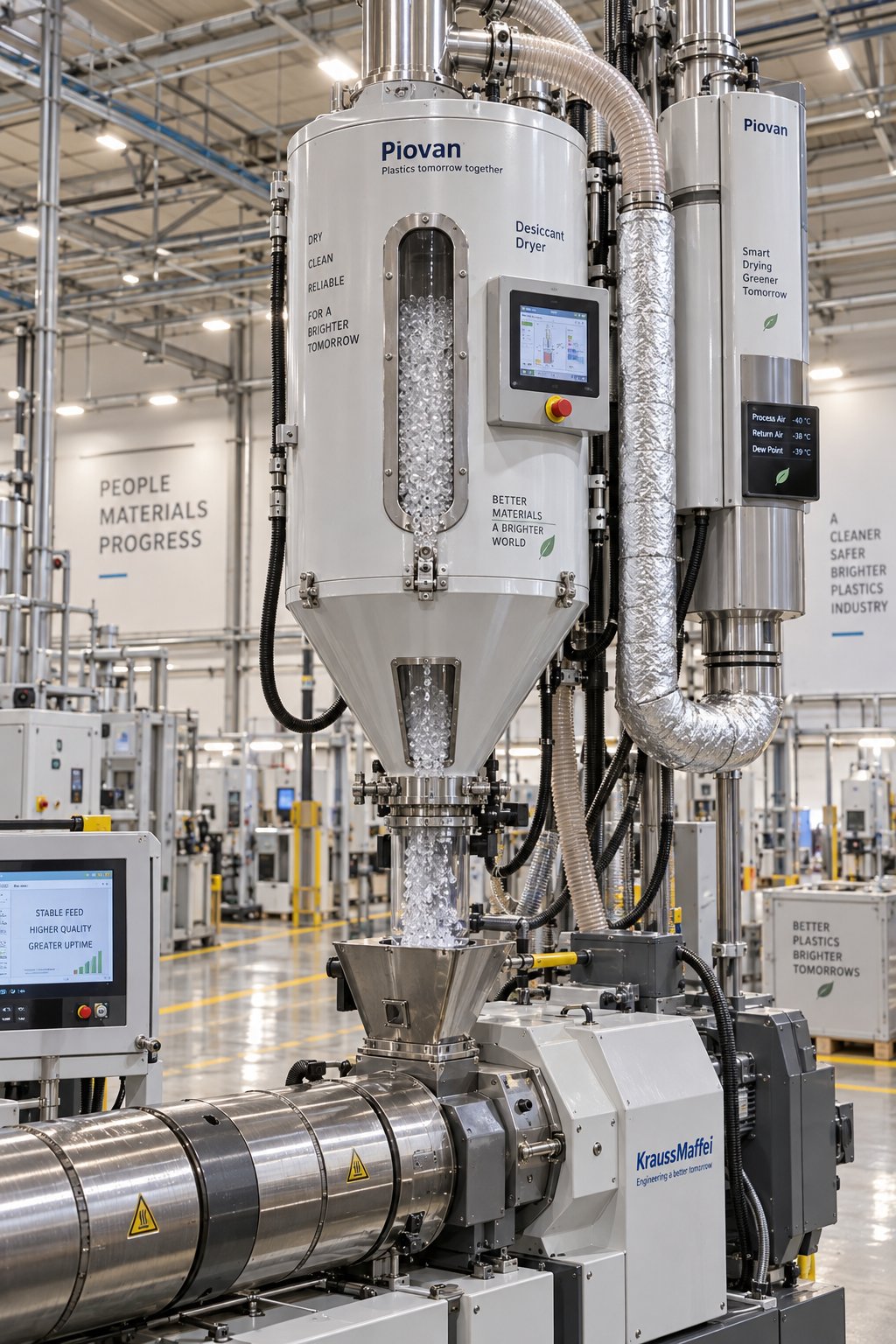
The only reliable defense against moisture defects in extrusion is thorough pre-drying with properly maintained equipment. Resin drying best practices emphasize that desiccant dryers - not simple hot air hoppers - are essential for hygroscopic materials because they control the dew point of the drying air, not just its temperature. A hot air dryer recirculates ambient moisture back through the resin, while a desiccant system strips moisture from the air stream before it contacts the pellets. Monitoring the dew point of the return air (target: -40 °C or lower for most engineering resins) is the single most important quality check on drying performance.
Over-drying is a real risk, too. Holding resin at elevated temperatures for too long can initiate thermal degradation before the material ever reaches the extruder barrel, particularly with heat-sensitive polymers like PET. The table below provides general drying guidance for commonly extruded hygroscopic resins.
| Resin Type | Recommended Drying Temperature | Typical Drying Time | Target Moisture Content |
|---|---|---|---|
| Nylon (PA6) | 75 - 85 °C (165 - 185 °F) | 4 - 6 hours | ≤ 0.10% |
| Nylon (PA66) | 75 - 85 °C (165 - 185 °F) | 4 - 6 hours | ≤ 0.10% |
| PET | 150 - 175 °C (300 - 345 °F) | 4 - 6 hours | ≤ 0.005% (50 ppm) |
| Polycarbonate (PC) | 120 - 130 °C (248 - 266 °F) | 3 - 4 hours | ≤ 0.02% |
| ABS | 80 - 85 °C (176 - 185 °F) | 2 - 4 hours | ≤ 0.05% |
| PMMA (Acrylic) | 75 - 80 °C (165 - 176 °F) | 3 - 4 hours | ≤ 0.04% |
| TPU | 80 - 110 °C (176 - 230 °F) | 2 - 4 hours | ≤ 0.02% |
Always cross-reference these ranges with the specific resin manufacturer's data sheet. Material grades within the same polymer family can have different optimal drying windows depending on their formulation and additive package.
Thermal Degradation and Discoloration
Imagine inspecting a natural-color extrudate and spotting scattered brown or black specks, or a gradual yellowing that intensifies along the length of a run. These are the signatures of thermal degradation - the polymer has been cooked. The damage is irreversible, and the discolored material must be scrapped.
Thermal degradation in a polymer extruder occurs when the combination of temperature and time exceeds what the resin's molecular structure can tolerate. Three process conditions are the usual culprits:
- Excessive residence time - when the extruder barrel is oversized relative to the throughput, or when production is running at reduced output, the melt spends too long at elevated temperatures. Polymer melt processing research confirms that residence time amplifies both thermal and oxidative degradation - the longer material remains in the barrel, the greater the chance of discoloration, gels, and brittleness.
- Dead spots in the flow channel - areas where the melt stagnates rather than flowing continuously are degradation incubators. Common locations include corners of adapter plates, poorly designed manifold transitions, and worn or corroded die channels where surface roughness traps a thin layer of polymer. That trapped material degrades over hours or days, then periodically breaks free as black specks or charred flakes that contaminate otherwise clean output.
- Localized overheating - a malfunctioning thermocouple or a heater band that has shorted to full power can push a single barrel zone well above the setpoint. The polymer in that zone degrades while the rest of the barrel remains within specification. Operators may not notice because the overall melt temperature averages out, but the localized damage shows up as intermittent specks or streaks.
Colorants themselves are vulnerable to thermal degradation as well. Organic pigments, which provide the brightest reds, yellows, and oranges, tend to have lower thermal stability than inorganic pigments. A color that looks perfect during a short qualification run may shift noticeably during extended production if the actual melt temperature creeps above the pigment's stability threshold. This is a subtle trap: the base polymer may tolerate the processing temperature without issue, but the colorant breaks down, producing a gradual shift toward brown or dull tones that only becomes apparent when parts are compared against the original standard.
Preventing thermal degradation and discoloration requires a three-pronged approach:
- Minimize residence time - match extruder size to production volume so the barrel is not holding excess melt. During extended stops, purge the system or reduce temperatures to a safe standby level rather than leaving hot resin sitting idle.
- Eliminate dead spots - design flow channels with streamlined geometry and smooth surface finishes. During scheduled maintenance, inspect adapters, screen changers, and die internals for buildup or corrosion that creates stagnation zones.
- Verify temperature control accuracy - calibrate thermocouples on a regular schedule and use independent spot checks with a handheld pyrometer to confirm that displayed temperatures match reality. A five-degree error in a critical zone can be the difference between clean product and degraded output.
Color defects and moisture-induced flaws share an important trait with the dimensional and structural problems covered earlier - they rarely exist in isolation. A resin that enters the extruder wet will not only produce splay marks but may also exhibit viscosity shifts that affect wall thickness and dimensional accuracy. A pigment that degrades thermally can release volatile byproducts that create additional surface bubbles or voids. Solving these interconnected problems demands the same systems-level thinking discussed in previous sections, and it becomes even more critical when the extrusion process itself introduces unique failure modes - as it does in blown film, pipe, profile, and co-extrusion operations.
Defects Specific to Blown Film and Profile Extrusion Types
Every extrusion process shares a common foundation - melt a polymer, push it through a die, cool it into a finished shape. But the moment that melt exits the die, each process type introduces its own physics, its own equipment, and its own ways of going wrong. A blown film line inflates a molten tube into a bubble suspended in midair. A pipe line forces the extrudate through a vacuum calibration sleeve submerged in water. A co-extrusion system merges two or more polymer streams into a single layered structure where the interface between materials becomes its own source of instability. The defects born from these process-specific conditions will not appear in a generic troubleshooting checklist, and they demand solutions tailored to the equipment and geometry involved.
Blown Film Extrusion Defects and Troubleshooting
Picture a blown film line running at speed. A molten tube emerges from a circular die, inflates into a bubble, rises through an air ring, passes a frost line where it solidifies, collapses through nip rollers, and winds onto a roll. Every one of those stages can introduce defects that are unique to this process - and blown film troubleshooting requires understanding how they interact.
Gauge variation is arguably the most costly blown film extrusion defect because it directly affects material usage and product performance. When film thickness varies across the width or around the circumference, some areas become over-engineered while others are too thin to meet specification. The causes, as blown film process analysis confirms, typically include uneven die flow distribution, temperature inconsistencies across the die, imbalanced cooling from the air ring, and variations in haul-off speed. Correcting gauge variation starts at the die - adjusting die bolts to equalize the gap around the circumference - and extends to verifying that the air ring delivers uniform cooling airflow at every angular position.
Bubble instability is one of the most disruptive issues an operator can face. The bubble oscillates, flutters, or breathes in and out, making consistent output impossible. Common triggers include inconsistent internal air pressure, uneven cooling airflow, die imperfections that create localized thin spots, and even ambient drafts in the production environment. Unstable bubbles generate uneven film thickness, increase waste, and force frequent line stoppages. The fix involves stabilizing air pressure control, balancing the air ring, and sometimes installing bubble cages or internal bubble stabilizers to dampen oscillation mechanically.
Haze and gels compromise optical clarity and surface quality. Haze often results from inadequate cooling - when the film does not solidify quickly enough below the frost line, surface crystallinity develops unevenly, scattering light and reducing transparency. Gels appear as small, hard specks embedded in the film and typically result from degraded polymer or cross-linked material that survives from the melt. Regular die cleaning, proper material handling to avoid contamination, and maintaining consistent melt temperatures help control both issues.
Wrinkles and edge defects typically originate downstream rather than at the die. Poor web alignment through the collapsing frame, uneven tension across the film width, incorrect collapsing frame geometry, and misaligned nip rollers all contribute. When it comes to thin film troubleshooting specifically, wrinkle sensitivity increases dramatically because thinner gauges have less structural rigidity to resist tension imbalances. Even slight misalignment in the nip rollers or inconsistencies in winding tension produce visible creases that render the film unusable for printing or laminating applications.
Pipe and Profile Extrusion Failure Modes
Pipe and profile extrusion share the challenge of producing a rigid, dimensionally precise cross-section that must hold its shape through vacuum calibration and cooling. The failure modes here revolve around geometry, internal structure, and the downstream equipment that shapes the still-soft extrudate.
Ovality - a pipe cross-section that measures round in one direction but slightly elliptical in another - is a frequent dimensional defect. According to PVC pipe production analysis, ovality usually occurs during the cooling stage when the pipe does not solidify evenly. Insufficient vacuum in the calibration tank, uneven water temperature distribution, or excessive haul-off tension can all distort the pipe shape before it fully hardens. Well-designed vacuum calibration systems with multiple calibration sleeves and stable vacuum pressure are critical for maintaining roundness. Closed-loop cooling water systems that maintain consistent temperature, combined with synchronized haul-off units applying uniform pulling force, prevent deformation.
Internal cracking and rough inner bore point to problems inside the die or at the mandrel. If the mandrel support (spider legs) disrupts melt flow, weld lines form where the melt streams reunite. These weld lines become crack initiation sites under pressure or impact loading. A rough inner bore typically results from inadequate melt temperature, improper die surface finish, or material stagnation at dead spots inside the die tooling. Raising melt temperature in the die zone and ensuring streamlined flow channel geometry improve inner surface quality.
Profile distortion from uneven cooling resembles warping in flat products, but three-dimensional profile geometries amplify the effect. A window frame profile with thick flanges and thin walls cools at different rates across its cross-section. The thick sections shrink more as they cool slowly, pulling the profile into a curve. Spray tank configuration becomes a critical corrective lever - directing more cooling water toward thick sections and reducing it on thin walls helps equalize solidification rates. Adjusting haul-off tension downward also reduces the mechanical stress applied to the still-pliable profile, giving it more freedom to cool without locking in distortion.
Co-Extrusion Layer Defects
Co-extrusion introduces a category of defects that simply cannot exist in single-material processing. When two or more polymer streams merge inside a feedblock or multi-manifold die, the interface between layers becomes a potential failure zone governed by its own set of physics.
Layer delamination means the layers separate from each other, either during production or in service. This happens when the polymers lack sufficient chemical compatibility or when the interface temperature is too low for adequate molecular diffusion between layers. Tie layers - adhesive resins specifically formulated to bond dissimilar polymers - solve the compatibility problem, but only if they are thick enough and hot enough at the merge point to function effectively.
Encapsulation occurs when the less viscous polymer wraps around the more viscous one instead of forming a clean, parallel layer structure. Research conducted at Sandia National Laboratories on multilayer coextrusion confirmed that mismatched viscosity between layers is a primary driver - when one polymer flows significantly more easily than the other, it migrates toward the high-shear die wall regions and progressively encapsulates the stiffer material. Their finite element simulations showed that at a viscosity ratio of 10:1, complete encapsulation occurs and the layered structure is lost entirely.
Interfacial instability produces visible zigzag or wave patterns at the boundary between layers. These instabilities, often described as ribbing or barring, arise from differences in viscosity and density between adjacent layers. The Sandia research demonstrated that even with identical viscosities, the geometry of the flow channel itself - particularly at splitter and restacking sections - can introduce non-uniform layer thickness. When viscosity and density mismatches are added on top of geometric effects, wave-like perturbations at the interface grow rather than damp out, producing an extrudate with irregular, undulating layers instead of clean parallel ones.
Uneven layer distribution means one layer is thicker than intended while another is thinner, even though the overall part dimensions may be correct. Imbalanced flow rates between extruders, pressure differences at the feedblock inlets, and temperature gradients that create viscosity variation between streams all contribute. Careful metering of each polymer stream and matching melt viscosities at the processing temperature are the primary preventive measures.
The table below organizes the key defects by extrusion process type, providing a quick reference for operators to identify the most likely cause and corrective direction based on their specific line.
| Extrusion Process | Defect | Primary Cause | Key Corrective Action |
|---|---|---|---|
| Blown Film | Gauge variation | Uneven die gap; imbalanced air ring cooling | Adjust die bolts for uniform gap; balance air ring airflow |
| Blown Film | Bubble instability | Inconsistent air pressure; uneven cooling; ambient drafts | Stabilize IBC pressure; install bubble stabilizers; shield from drafts |
| Blown Film | Haze | Inadequate cooling below frost line | Increase air ring volume; lower cooling air temperature |
| Blown Film | Gels | Degraded or cross-linked polymer in the melt | Clean die; check for dead spots; review material handling |
| Blown Film | Wrinkles | Misaligned nip rollers; uneven web tension | Realign collapsing frame and nip rollers; balance winding tension |
| Pipe | Ovality | Uneven cooling; insufficient vacuum; excessive haul-off tension | Equalize calibration vacuum; balance cooling water temperature; reduce haul-off speed |
| Pipe | Internal cracking | Weld line weakness from spider-leg mandrel supports | Optimize mandrel design; raise die zone temperature to improve weld-line fusion |
| Pipe | Rough inner bore | Low melt temperature; die surface roughness; stagnation | Increase melt temperature; polish mandrel surfaces; eliminate flow dead spots |
| Profile | Profile distortion | Uneven cooling across thick and thin wall sections | Direct more cooling to thick sections; reduce haul-off tension; extend cooling length |
| Co-Extrusion | Layer delamination | Poor chemical compatibility; insufficient interface temperature | Add or thicken tie layer; raise melt temperature at merge point |
| Co-Extrusion | Encapsulation | Large viscosity mismatch between layers | Match melt viscosities by adjusting temperatures; redesign feedblock geometry |
| Co-Extrusion | Interfacial instability (zigzag/wave) | Viscosity and density differences between adjacent layers | Minimize viscosity ratio; reduce flow rate; add quieting zones after splitters |
| Co-Extrusion | Uneven layer distribution | Imbalanced flow rates; pressure or temperature gradients | Meter each stream precisely; equalize melt temperatures between extruders |
What connects every defect in this table - whether it is a fluttering blown film bubble, an oval pipe, or an encapsulated co-extrusion layer - is that the root cause almost always traces back to how the polymer melt was prepared and delivered before it reached the downstream equipment. And the single most influential, yet consistently overlooked, element in that melt preparation chain is the component sitting at the heart of every extruder: the screw itself.
How Screw Design Drives or Prevents Extrusion Defects
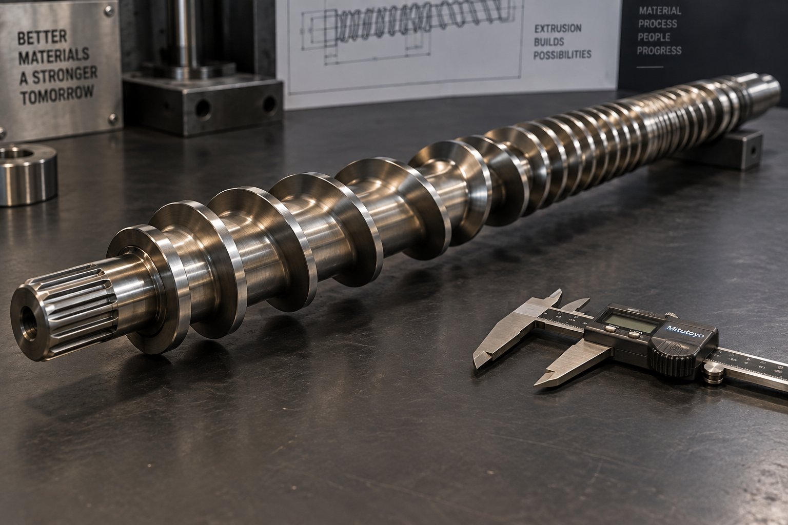
Most troubleshooting conversations start at the operator panel - barrel temperatures, screw speed, line speed. Those are the variables you can change with a button press. But what about the variable you cannot change mid-run? The screw itself - its geometry, its compression ratio, its mixing capability - quietly determines whether your plastic extruder produces consistent, defect-free output or fights you with every meter of product. A screw mismatched to the polymer it processes will generate defects that no amount of parameter tuning can fix, because the problem is mechanical, not procedural.
Think of it this way: process parameters are the fine-tuning knobs, but screw design is the foundation they sit on. If the foundation is wrong, turning the knobs just moves the problem around. Screw and barrel performance analysis confirms that subtle mismatches in flight depth, channel width, or compression ratio lead to shear overheating, poor melting homogeneity, and excessive residence time - all of which translate directly into the defects covered throughout this guide.
Compression Ratio and Melt Homogeneity
The compression ratio of an extruder screw describes how much the channel depth decreases from the feed zone to the metering zone. A screw with a deep feed section and a shallow metering section has a high compression ratio; one where the depth change is modest has a low ratio. This single geometric parameter controls how aggressively the screw compacts and melts the incoming pellets - and getting it wrong in either direction produces distinct, predictable defects.
Too-low compression ratio: The screw does not compact the solid bed of pellets tightly enough against the barrel wall. Pellets survive partially unmelted into the metering zone, where they pass through the die as gels - hard, visible specks embedded in the extrudate. You will also see surface roughness because the melt surrounding those unmelted particles is not thermally uniform. The extrudate may have inconsistent gloss and a gritty texture that no temperature adjustment eliminates, because the root cause is insufficient mechanical energy input from the screw geometry itself.
Too-high compression ratio: The screw over-compresses the melt, generating excessive shear heat in the transition zone. The actual melt temperature climbs well above the barrel setpoint - sometimes by 15 to 20 degrees Celsius - because frictional energy overwhelms the cooling capacity of the barrel. The result is thermal degradation: yellowing, brown specks, and in severe cases, black carbonized particles that contaminate the output. Polymers with narrow processing windows, like PVC or PVDF, are especially vulnerable. You might also notice erratic pressure readings at the die, because the overheated melt has dramatically lower viscosity than expected, disrupting the pressure-flow balance.
The correct compression ratio depends entirely on the polymer being processed. Semi-crystalline resins like HDPE, which undergo a sharp solid-to-liquid transition, generally require higher compression ratios than amorphous materials like polystyrene, which soften gradually. Running a general-purpose screw across multiple resin families almost guarantees suboptimal melting for at least some of them.
Metering Zone Design and Pressure Stability
If compression ratio governs melt quality, the metering zone governs output stability. The metering section is the final stretch of the screw before the melt reaches the die - a constant-depth channel that should deliver a steady, uniform flow of fully melted polymer at consistent pressure. When the metering zone is too short, the results show up immediately on the production floor as surging: a rhythmic pulsation in output rate that produces alternating thick and thin sections in the extrudate.
Extrusion engineering research explains the mechanism clearly. A partially filled metering section fills backward until it can balance the head pressure. When equilibrium is reached, the drag flow minus the pressure flow equals the actual output. But because there is a delay between equalization and the system's response, a harmonic variation develops - a cyclic pulse that keeps oscillating until something changes to provide more back-fill and dampen the response. The result on your product? Dimensional variation that repeats at regular intervals, visible as periodic wall thickness changes in pipe, gauge bands in film, or weight fluctuation in cut-to-length profiles.
The critical insight from that research is that a minimum metering-zone fill length is necessary to prevent this cyclic instability. For most polymers and operating conditions, at least two full flights of metering-zone fill are the absolute minimum, and lower-viscosity resins or lower head pressures may require three to four flights of fill to dampen the surge completely. Plastic extruders running two-stage vented screws are especially susceptible because the second metering section may not have been designed for the actual operating head pressure.
A practical diagnostic: if your line exhibits a rhythmic surge, try increasing the head pressure slightly - for example, by using a finer screen pack. If the surge frequency and magnitude decrease, a partially filled metering section is almost certainly the culprit, confirming that the screw's metering zone length is insufficient for the current operating conditions.
Mixing Elements and Their Impact on Defect Reduction
Even a screw with the ideal compression ratio and metering zone length can still produce color streaks, additive distribution failures, and thermal non-uniformity if it lacks adequate mixing capability. Two types of mixing are at play, and each addresses a different family of defects.
Dispersive mixing applies high-shear stress to break apart agglomerates - pigment clusters, filler clumps, or gel particles. Wider kneading elements and barrier-style flights create the intense shear fields needed for this work. As screw profile design research from NC State details, wider kneading blocks (full-disk-width elements) promote dispersive mixing, while narrower elements contribute more toward distributive action. Without sufficient dispersive capability, pigment agglomerates survive intact through the die, showing up as the color streaks discussed in earlier sections.
Distributive mixing folds and reorients the melt to spread already-dispersed particles evenly throughout the volume. Toothed mixing elements, pin-style mixers, and narrow kneading blocks excel at this. Poor distributive mixing leaves the melt thermally stratified - hot near the barrel wall, cooler near the screw root - which creates viscosity gradients that cause uneven die flow, dimensional variation, and inconsistent surface finish.
A plastics extruder equipped with both dispersive and distributive mixing sections in the right locations along the screw length can eliminate an entire class of defects that no amount of temperature or speed adjustment will fix. The screw essentially becomes the first line of quality defense, handling melt homogeneity before the polymer ever reaches the die.
Screw design is the single most underappreciated variable in defect prevention. Operators spend hours adjusting temperatures and speeds while the real limitation sits inside the barrel, unchangeable until the next screw pull.
The following list pairs common defect symptoms with the screw design element most likely responsible - a quick reference for determining whether your problem is a process issue or a hardware issue:
- Unmelted particles or gels in the extrudate - compression ratio too low; insufficient transition zone length for the polymer's melting behavior
- Thermal degradation (yellowing, black specks) - compression ratio too high, generating excessive shear heat; also check for worn screw flights that increase residence time
- Cyclic output surging (rhythmic thick/thin variation) - metering zone too short for the operating head pressure; partially filled metering section creating harmonic pressure oscillation
- Color streaks and pigment agglomerates - insufficient dispersive mixing; screw lacks high-shear kneading or barrier elements in the metering zone
- Uneven melt temperature (hot spots/cold spots) - inadequate distributive mixing; screw does not reorient melt layers enough to equalize cross-channel temperature gradients
- Pressure fluctuation at the die - metering zone design does not match the polymer viscosity and head pressure requirements; consider a longer metering section or optimized flight geometry
- Erratic output rate despite stable screw speed - feeding instability caused by improper feed-zone flight depth or barrel surface finish for the specific resin's frictional characteristics
When troubleshooting leads you to suspect screw geometry as the root cause, the path forward involves matching the screw specification to the specific polymer, throughput, and head pressure of your operation - not relying on a general-purpose design that compromises on everything. For extrusion plants dealing with persistent output instability, melt-quality problems, or pressure fluctuation that process adjustments cannot resolve, specialized screw barrel support from NANHAIYA provides the engineering guidance needed to identify whether the screw geometry itself is the limiting factor and what design changes will eliminate the defect at its source.
Matching screw hardware to your process is a powerful step, but even the best-designed screw cannot help if you are chasing the wrong defect first. With dozens of possible flaws competing for attention on a busy production floor, the question becomes: which problems deserve your resources before all the others? That prioritization decision is itself a skill - one built on data, not instinct.
A Prioritization Framework for Extrusion Defect Troubleshooting
A busy extrusion line might be producing surface roughness on one product, dimensional drift on another, and occasional color streaks on a third - all during the same shift. The instinct is to chase whichever problem the customer is complaining about loudest, or whichever defect the operator spotted most recently. That reactive approach burns resources on low-impact issues while high-frequency problems quietly eat into scrap budgets week after week. Quality engineering offers a better path: let production data decide where your troubleshooting effort goes first.
Two foundational tools make this possible. The Pareto chart identifies which defects cause the most damage. The Ishikawa (fishbone) diagram uncovers why those top offenders keep happening. Used together, they transform extrusion defect troubleshooting from a guessing game into a structured, data-driven cycle that delivers the highest return on every hour your team invests in problem-solving.
Building a Defect Pareto Chart for Your Extrusion Line
The Pareto principle - often summarized as the 80/20 rule - holds that a small number of causes typically account for the majority of effects. In extrusion plastics operations, this means a handful of defect types usually generate most of your scrap, rework, and customer rejections. A Pareto chart makes that imbalance visible so you can act on it.
Here is how to build one from your own production data:
- Categorize reject types clearly. Define distinct defect categories that operators can identify consistently - surface roughness, dimensional out-of-spec, color deviation, voids, warping, moisture-related flaws, contamination. Vague labels like "bad quality" or "rejected" make the chart useless. Every reject needs a specific category.
- Tally frequency over a defined period. Choose a timeframe long enough to capture meaningful patterns - two weeks to one month works well for most extrusion operations. Record every defect occurrence by category, either from inspection logs, reject bins, or automated quality monitoring systems. As quality engineering frameworks recommend, aim for a minimum of 30 data entries to ensure statistical reliability.
- Rank by cumulative impact. Sort defect categories in descending order by frequency. Calculate each category's percentage of the total and its cumulative percentage. Plot the categories as bars (tallest on the left) and overlay the cumulative percentage as a rising line.
- Identify the vital few. Find the point on the cumulative line where it crosses the 80% threshold. Every defect category to the left of that cutoff represents your "vital few" - the small group of problems that collectively account for the lion's share of your quality losses. These are your top-priority targets.
The shape of the cumulative line tells you something important. A steep initial rise that quickly flattens confirms a strong Pareto distribution - clear priorities exist and focused effort will pay off. A gradual, nearly linear rise (sometimes called a "flat Pareto") signals that defects are distributed more evenly across categories. When that happens, you need to stratify - break broad categories into sub-categories and run a second-level Pareto on the dominant group to find more specific targets.
One more consideration: frequency is not always the right metric. A defect that happens rarely but requires expensive rework or triggers a customer shutdown may cost more than a high-frequency nuisance flaw. A cost-weighted Pareto chart, where the bar height represents total cost rather than occurrence count, can completely reorder your priorities. Run both versions and compare - the differences are often eye-opening.
Root Cause Analysis Beyond Surface-Level Fixes
A Pareto chart tells you what to fix first. It does not tell you why the defect keeps occurring. That is where the Ishikawa diagram - also known as the fishbone diagram - picks up. This tool visually maps every potential cause of a specific defect, organized into structured categories, so your team can systematically investigate rather than guess.
The classic framework uses six categories, often called the 6Ms. Applied specifically to extrusion, they look like this:
- Machine - barrel and screw wear, die condition, heater band function, thermocouple accuracy, vacuum calibrator alignment, cooling system performance
- Material - resin lot variation, moisture content, regrind contamination, additive or masterbatch compatibility, bulk density changes
- Method - temperature profile selection, screw speed settings, startup and shutdown procedures, purging protocols, parameter documentation
- Manpower - operator training level, shift-to-shift consistency in procedures, communication of process changes, experience with specific resin grades
- Measurement - gauge calibration, dimensional inspection frequency, moisture analyzer accuracy, melt temperature verification methods
- Mother Nature (Environment) - ambient temperature and humidity fluctuations, cooling water supply temperature variations, seasonal changes affecting feedstock moisture uptake
Imagine your Pareto chart reveals that dimensional variation is the top defect on your pipe line. You draw the fishbone with "Dimensional Variation" at the head. Under Machine, the team lists worn calibration sleeves, inconsistent vacuum level, and haul-off belt wear. Under Material, they note recent resin lot changes and regrind ratio fluctuations. Under Method, they flag the absence of a documented startup procedure, meaning each shift operator sets initial haul-off speed differently. Under Measurement, someone points out that the ultrasonic wall thickness gauge has not been calibrated in three months.
Each branch generates specific, testable hypotheses. The team votes on the most likely root causes - a simple multi-voting technique where each member places three marks on the causes they consider most probable. The top-voted causes become investigation targets, verified with data rather than opinion. A published case study using this fishbone approach demonstrated that structured root cause analysis reduced incident rates dramatically when the identified causes were addressed with targeted improvement actions.
The key discipline? Do not stop at the first plausible explanation. Ask "why" at least five times for each candidate cause. "The wall thickness drifts" leads to "because haul-off speed is inconsistent," which leads to "because belt grip is slipping," which leads to "because the belts are worn," which leads to "because there is no scheduled belt replacement interval." That final answer - the missing maintenance protocol - is the root cause worth fixing.
Defect-to-Process-Parameter Mapping
Once you have identified your vital few defects and drilled into their root causes, the next practical question is: which process parameters do I monitor and adjust for each defect family? The table below provides a comprehensive mapping. Primary contributors are marked with P, secondary contributors with S. Use this as a reference when diagnosing recurring issues - if a defect persists after adjusting its primary parameters, investigate the secondary ones before assuming a hardware problem.
| Defect Family | Barrel Temperature | Die Temperature | Screw Speed | Back Pressure | Cooling Rate | Line Speed |
|---|---|---|---|---|---|---|
| Surface Roughness / Melt Fracture | P - Increase to reduce shear stress | P - Increase to lower melt viscosity at die exit | P - Decrease to reduce shear rate | S - Monitor for excessive restriction | S - Excessive cooling near die can worsen | P - Decrease to lower throughput demand |
| Dimensional Variation | S - Affects viscosity and output consistency | S - Affects die swell behavior | P - Directly controls output rate | S - Influences melt density and flow stability | P - Uneven cooling distorts dimensions | P - Haul-off/output ratio governs wall thickness |
| Color Issues (streaking, shift) | P - Uniformity critical for even pigment distribution | S - Overheating degrades colorant | P - Affects mixing intensity and residence time | S - Higher pressure improves melt homogeneity | S - Minimal direct effect | S - Minimal direct effect |
| Voids / Internal Bubbles | S - Too high may volatilize additives | S - Minimal direct effect | S - Affects melt compaction | P - Increase to eliminate trapped air | P - Too rapid cooling traps voids before they collapse | S - Slower speed allows more consolidation time |
| Warping | S - Affects melt orientation and stress state | S - Influences die swell symmetry | S - Higher speed increases orientation | S - Minimal direct effect | P - Uneven cooling is the dominant cause | P - Excessive draw ratio locks in asymmetric stress |
| Moisture Defects (splay, foaming) | S - Higher temps accelerate hydrolysis in wet resin | S - Minimal direct effect | S - Higher speed reduces residence time (minor benefit) | S - Higher pressure suppresses bubble nucleation slightly | S - Minimal direct effect | S - Minimal direct effect |
Notice that moisture defects have almost no primary process-parameter lever on the extruder itself - the fix is upstream in the drying system. This mapping reinforces a point made throughout this guide: not every defect is solvable at the operator panel. Some require material preparation changes, some require screw design changes, and some require maintenance actions that prevent the defect from occurring in the first place.
That last category - prevention over correction - is where the most mature extrusion operations distinguish themselves. Diagnosing and fixing a defect after it appears is necessary work, but the real gains come from eliminating the conditions that allow defects to develop at all. Scheduled maintenance, wear monitoring, and systematic process documentation form the backbone of that preventive approach.
Preventive Maintenance That Stops Defects Before They Start
Every defect discussed so far in this guide - from melt fracture to co-extrusion layer instability - shares a common trait: by the time you see it, the damage is already done. Scrap is accumulating, the line may need to stop, and your team is in reactive mode, chasing a root cause under pressure. The most effective extrusion operations flip that equation. They invest in scheduled inspections, wear tracking, and process documentation that catch problems while they are still brewing inside the barrel, not after they have ruined a production run. Extrusion preventive maintenance is not glamorous work, but it is the single highest-leverage activity for reducing defect frequency over time.
The difference between reactive troubleshooting and proactive maintenance culture comes down to timing. Reactive plants fix what breaks. Proactive plants measure what is wearing, document what is changing, and replace or adjust components before they cross the threshold into defect-producing territory. The payoff shows up in overall equipment effectiveness - less unplanned downtime, fewer quality holds, and a production floor where operators spend their energy running good product instead of diagnosing bad product.
Scheduled Die and Screw Maintenance Protocols
When was the last time you pulled the screw out of your extruder and actually measured it? If the answer is "not recently," you are not alone - but you are also running blind. Screw barrel wear in extrusion is gradual and invisible from the outside. The screw diameter shrinks flight by flight, the barrel bore grows, and the clearance between them widens. That growing gap directly produces specific defects: reduced output at a given RPM, inconsistent melt temperature because the leakage flow back over the flights increases, and loss of pressure-building capability that leads to surging and dimensional variation.
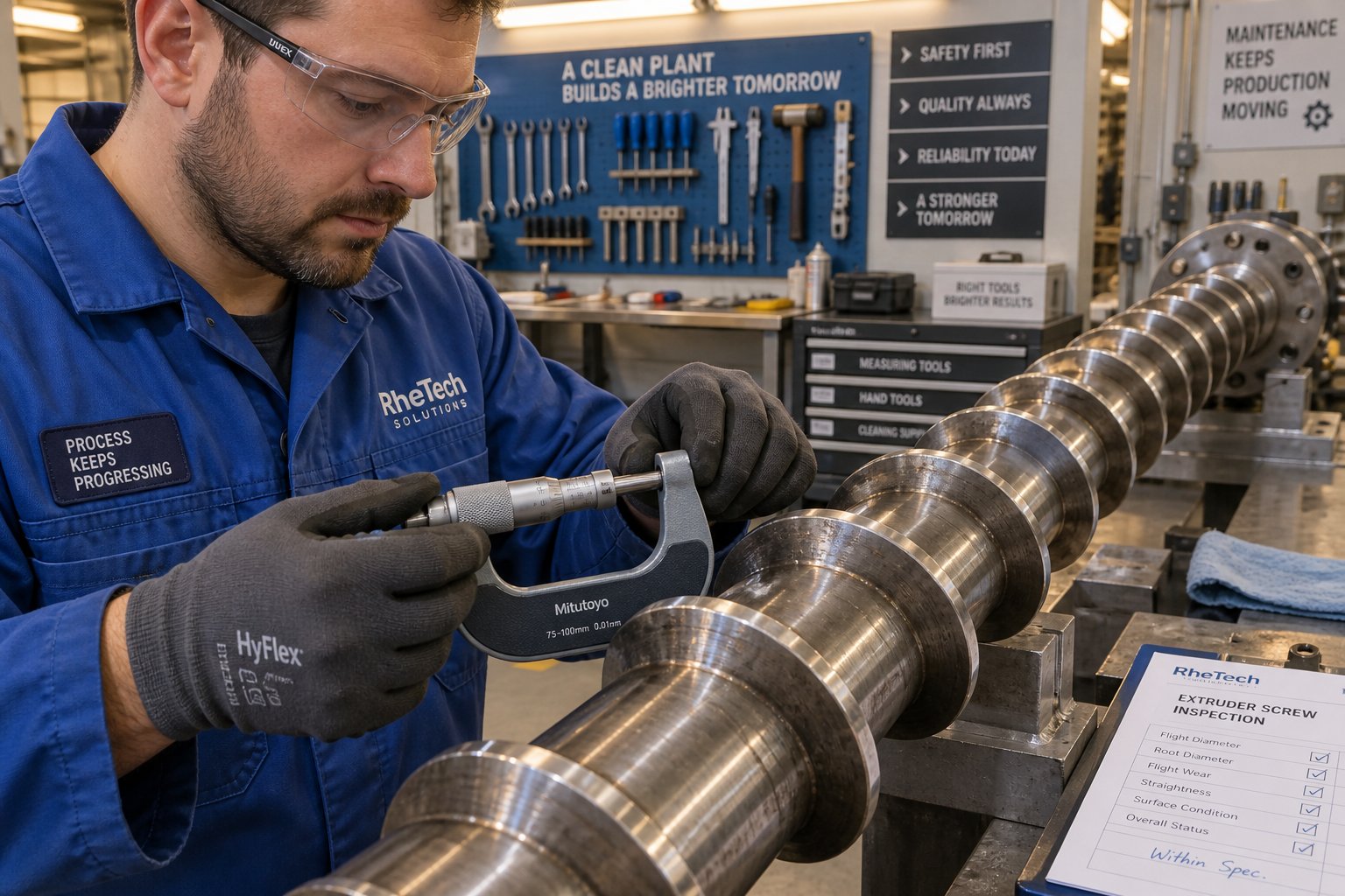
Feedscrew maintenance protocols from Davis-Standard outline a practical measurement process that every extrusion plant should adopt. The procedure starts with pulling the screw, cleaning it carefully using brass tools and copper gauze - never steel wire brushes or abrasive materials that could damage the flight surfaces - and allowing it to cool to room temperature before any measurements are taken. Each flight is numbered, and an OD bar micrometer measures the outer diameter at every flight position along the screw length. Those measurements are plotted against the original dimensions, creating a visual wear profile that reveals exactly where the screw has lost material and how severely.
The barrel side requires equal attention. Bore measurements at multiple positions along the barrel length detect ovality and localized wear zones, particularly in the transition and metering sections where the compressive forces on the melt are highest. Industry practice recommends measuring screw flight diameter and barrel bore every 500 to 1,000 operating hours and tracking clearance growth over time. That tracking reveals the wear trajectory long before output drops or defects spike, giving you a window to plan a rebuild or replacement during a scheduled shutdown rather than an emergency stop.
Die maintenance follows a similar philosophy. Regular disassembly and cleaning of the die and adapter removes plate-out buildup, degraded polymer, and additive deposits that cause die lines, surface streaks, and flow disruption. Inspect flow channel surfaces for corrosion, pitting, or scoring during every split-and-clean procedure. A die lip that develops a nick from careless handling will imprint that mark on every meter of extrudate until someone catches it - and on a blown film extrusion maintenance schedule, catching it early means inspecting die components at defined intervals rather than waiting for a customer complaint.
Screen Pack and Breaker Plate Management
The screen pack sits between the screw tip and the die, filtering contaminants and building back pressure that improves melt quality. It is also a consumable component that degrades with every hour of operation - and ignoring it creates a cascade of problems that mimic other defect types, making diagnosis frustrating if you are not monitoring screen condition.
As debris accumulates on the mesh, the pressure upstream of the screen rises. That pressure increase is gradual at first, but it accelerates as the screen approaches full blockage. The consequences unfold in stages:
- Mild blockage - back pressure rises slightly, which may actually improve melt quality temporarily. Output remains stable, and operators may not notice any change.
- Moderate blockage - pressure spikes become visible on the gauge. Output starts to fluctuate as the extruder struggles to push melt through the restricted area. Dimensional variation appears in the product. Sensitive processes like blown film extrusion show gauge inconsistency.
- Severe blockage - the pressure differential across the screen becomes so large that contamination breaks through, either by tearing the mesh or by forcing particles through gaps at the screen edges. At this point, the screen is no longer filtering anything meaningful, and degraded material trapped upstream begins releasing into the melt stream as black specks or gels.
Screen pack maintenance best practices recommend monitoring the pressure differential across the screen continuously, not just checking the upstream pressure gauge occasionally. Installing pressure sensors both before and after the screen pack reveals the actual restriction level in real time. Trends in that differential - tracked in a log book or process historian - tell you exactly when a screen change is due before the blockage reaches the stage where it affects product quality.
For operations running contaminated or recycled feedstocks, manual screen changes during production stops may not be frequent enough. Continuous screen changers - slide-plate or rotary designs that swap fresh screen into the melt stream without stopping the extruder - eliminate the production interruption entirely and keep filtration performance consistent. The upfront investment pays for itself in reduced scrap and downtime, particularly on high-volume lines where every minute of stoppage carries significant cost. Cleaning the screen pack every 200 to 400 hours, depending on material type and contamination level, keeps the system operating in the mild-blockage zone where back pressure actually benefits melt quality rather than degrading it.
Process Documentation and Defect Prevention Culture
Imagine this scenario: a particular color shift defect appeared on your line six months ago, and an experienced operator solved it by adjusting the metering zone temperature and switching to a finer screen pack. That operator has since moved to another shift. The same defect reappears today, and the current crew spends three hours rediscovering the same fix from scratch - burning material, time, and patience in the process.
This is what happens without process documentation. Every hard-won solution lives only in the memory of whoever found it, and every personnel change, shift rotation, or vacation resets the learning curve to zero. Building a defect prevention culture means capturing that knowledge systematically so the entire organization benefits.
Three documentation practices form the backbone of this approach:
- Parameter logs - record the complete set of process conditions for every production run: barrel zone temperatures (setpoints and actuals), die temperature, screw speed, melt pressure, melt temperature, line speed, and cooling parameters. When a defect appears, these logs allow you to compare current conditions against the last known good run and pinpoint what changed.
- Defect occurrence records - every reject gets categorized, counted, and tagged with the production conditions under which it occurred. Over weeks and months, these records reveal patterns that are invisible in the moment - a particular defect that only appears during the night shift, or only when running a specific resin lot, or only after the screen pack has been in service for more than 300 hours.
- Material lot tracking - link incoming resin lots to the production runs where they were consumed. When a defect correlates with a specific lot number, you have actionable evidence to take back to the resin supplier rather than a vague complaint about "inconsistent material."
Thermocouple calibration deserves special mention within this documentation framework. A thermocouple that drifts by five degrees does not trigger an alarm - it simply reports a slightly wrong number that the control system accepts as truth. The barrel heats to the wrong temperature, the melt viscosity shifts, and the defect pattern changes in ways that seem random until someone discovers the calibration error. Scheduling thermocouple checks at regular intervals and recording the deviation found at each check builds a calibration history that flags sensors trending toward inaccuracy before they cause problems.
Pulling all of these practices together into a single maintenance rhythm keeps the program manageable. The following checklist outlines a recommended sequence that covers the critical components of extrusion preventive maintenance:
- Daily: Record all process parameters at the start and end of each shift. Perform visual inspection of the die exit for buildup, the extrudate for surface quality, and the hopper for material bridging or contamination.
- Weekly: Check heater band contact and function across all barrel zones. Verify cooling water flow rates and temperatures. Inspect the feed throat cooling system. Review the week's defect occurrence log for emerging patterns.
- Monthly: Calibrate thermocouples and pressure transducers against reference standards. Inspect screen changer seals and breaker plate condition. Check gearbox oil level, color, and contamination. Tighten electrical connections and inspect wiring for heat damage.
- Quarterly: Perform a screw pull inspection - measure flight OD at every flight position and compare to the baseline. Measure barrel bore diameter at multiple points. Inspect die flow surfaces for wear, corrosion, or scoring. Evaluate haul-off belts, rollers, and calibration sleeves for wear.
- Semi-annually: Full die disassembly, cleaning, and repolishing of flow surfaces. Comprehensive motor and drive system inspection including bearing temperatures, vibration analysis, and alignment verification. Review and update all process parameter documentation and defect response procedures.
For extrusion plants and recycling operations where screw barrel wear, overheating, blockage, or persistent extruder performance issues are driving recurring quality problems, partnering with a specialist accelerates the diagnostic process. NANHAIYA's screw barrel support provides practical engineering guidance for operations managing these wear-related challenges - helping teams identify whether their maintenance intervals, component specifications, or replacement timing need adjustment to keep defect rates under control.
A disciplined maintenance program does not just prevent individual defects - it creates the stable process foundation that makes every other troubleshooting effort more effective. When your screw is in spec, your screens are fresh, your thermocouples read true, and your documentation captures what works, the remaining defects become far easier to isolate and solve. That stability is what transforms a reactive operation into one that manages quality proactively - and it sets the stage for bringing together every diagnostic principle covered in this guide into a single, repeatable defect management cycle.
Bringing It All Together for Defect-Free Extrusion
Solving one defect on one shift is troubleshooting. Building a system that consistently prevents defects across every product, every material, and every operator - that is quality management. The difference between the two is not technical knowledge alone. It is discipline: a repeatable cycle that treats every flaw as data, every fix as a lesson, and every production run as an opportunity to refine the process further. Whether you are running extrusion plastic operations for packaging film or producing structural profiles, the diagnostic principles remain the same.
The Complete Defect Management Cycle
Effective defect management in plastics extrusion follows a five-stage lifecycle. Skip any stage and the cycle breaks - problems recur, knowledge is lost, and the team stays trapped in reactive mode.
The stages flow in order: Detection catches the flaw through visual inspection, dimensional measurement, or automated monitoring. Diagnosis traces the symptom backward through the line to its root cause using the fishbone framework and variable-interaction thinking covered earlier. Correction applies the targeted fix - adjusting process parameters, replacing worn components, or addressing material preparation failures. Prevention embeds the solution into scheduled maintenance routines, screw design specifications, and drying protocols so the same defect cannot return unnoticed. Documentation captures what happened, what fixed it, and what to monitor going forward, so the entire organization learns from every incident.
Sustainable quality improvement in extrusion of plastics requires all five stages - Detection, Diagnosis, Correction, Prevention, and Documentation - working as a continuous loop, not just reactive fixes applied under pressure.
Key Takeaways for Extrusion Operators and Engineers
Consider this list a floor-ready reference - the essential principles from this guide distilled into a checklist you can return to whenever a new problem surfaces on your plastics extrusion line:
- Screw design is foundational, not optional. Compression ratio, metering zone length, and mixing elements determine melt quality before any process parameter takes effect. If parameter adjustments cannot solve the defect, suspect the screw geometry.
- Variable interactions are real and unavoidable. Changing temperature shifts viscosity, which shifts pressure, which shifts output rate. Never adjust one parameter without monitoring at least two related ones.
- Moisture control is non-negotiable for hygroscopic materials. Splay, brittleness, and viscosity drops from undried nylon, PET, or polycarbonate cannot be corrected at the barrel - only prevented at the dryer.
- Pareto analysis directs effort where it matters most. Let production data identify your vital few defects rather than chasing whichever problem appeared most recently.
- Preventive maintenance reduces defect frequency more reliably than reactive troubleshooting. Scheduled screw measurement, screen changes, thermocouple calibration, and die cleaning eliminate root causes before they produce visible flaws.
- Process documentation turns individual fixes into organizational knowledge. Parameter logs, defect records, and material lot tracking reveal patterns invisible in the moment and prevent the same problem from being solved twice.
- Every extrusion type has unique failure modes. Blown film gauge variation, pipe ovality, and co-extrusion layer instability each demand process-specific diagnostic approaches - generic checklists miss them entirely.
Defect-free extrusion is not a destination you arrive at once. It is a discipline you practice continuously - refining your understanding of how materials, machines, and methods interact across the full line. The operators and engineers who master that discipline do not just produce better product. They build extrusion plastic operations that improve with every run.
Frequently Asked Questions About Plastic Extrusion Defects
1. What are the most common plastic extrusion defects?
The most frequently encountered plastic extrusion defects include surface flaws like melt fracture, sharkskin, and die lines; dimensional problems such as warping, uneven wall thickness, and ovality; structural issues including voids and sink marks; and appearance-related failures like color streaking, splay marks, and thermal discoloration. Each defect category traces back to specific process variables - surface defects often relate to shear stress and die conditions, dimensional flaws stem from cooling imbalances and haul-off speed mismatches, and color or moisture defects point to upstream material preparation failures. Identifying which category your defect belongs to is the first step toward an efficient fix.
2. How do you fix melt fracture in plastic extrusion?
Melt fracture occurs when polymer chains exceed the critical shear stress inside or at the exit of the die, producing severe surface distortion on the extrudate. To correct it, raise the die zone temperature in small increments of 5 to 15 degrees Celsius to reduce melt viscosity at the exit point. Simultaneously, decrease screw speed to lower the volumetric flow rate and shear rate through the die. Where equipment allows, increasing die land length gives the melt more relaxation time before exiting. In persistent cases, switching to a resin grade with a broader molecular weight distribution shifts the onset of melt fracture to higher output rates, allowing you to maintain productivity without sacrificing surface quality.
3. What causes voids and bubbles in extruded plastic profiles?
Voids and internal bubbles in extruded profiles result from three primary mechanisms. Trapped air enters with feed pellets or through a starved feed zone and survives into the finished product when back pressure is too low to expel it. Insufficient melt pressure allows the interior of thick-walled sections to pull apart during cooling as the core shrinks faster than the solidified outer skin can follow. Moisture in hygroscopic resins like nylon, PET, or polycarbonate vaporizes inside the barrel and creates steam pockets that become permanent voids. Corrective steps include increasing back pressure to compact the melt, adjusting vacuum calibration levels on sizing equipment, slowing line speed for thick cross-sections, and ensuring thorough pre-drying with desiccant dryers for moisture-sensitive materials.
4. How does screw design affect extrusion defect rates?
Screw geometry is one of the most underappreciated factors in extrusion defect prevention. A compression ratio that is too low leaves unmelted pellets in the melt, producing gels and surface roughness. A ratio that is too high generates excessive shear heat, causing thermal degradation, yellowing, and black specks. Metering zone length directly governs output stability - a zone that is too short creates cyclic surging that shows up as periodic wall thickness variation. Mixing elements also play a critical role: dispersive mixing sections break apart pigment agglomerates to prevent color streaks, while distributive mixing sections equalize melt temperature to improve dimensional consistency. When process parameter adjustments fail to resolve a defect, the screw specification itself is often the limiting factor.
5. What preventive maintenance reduces plastic extrusion defects?
A structured preventive maintenance program targets the root causes of defects before they produce visible flaws. Key practices include pulling and measuring the screw every 500 to 1,000 operating hours to track flight wear and barrel clearance growth, scheduling regular die disassembly and repolishing to prevent buildup and die lines, monitoring screen pack pressure differential continuously to time changes before blockage affects output, and calibrating thermocouples monthly to ensure accurate temperature control. Process documentation - including parameter logs, defect occurrence records, and material lot tracking - reveals recurring patterns and preserves troubleshooting knowledge across shift changes. Together, these practices create a stable process foundation where remaining defects become far easier to isolate and correct.
Written by
Nanhaiya Technical Team
Zhoushan Nanhaiya Plastic Machinery Co., Ltd.
The Nanhaiya technical team supports screw and barrel manufacturing projects through application review, technical communication, custom manufacturing coordination, and production and quality control.
Discuss Your Application
Related Articles
More insights on screw barrel technology and plastics processing.

What Nobody Tells You About Screw Barrel For Plastic Machine Design
Oct 10, 2026
Learn how screw barrel for plastic machine design affects melt quality, throughput, and wear life. Covers geometry, resin matching, troubleshooting, and sourcing.
Read Article
Single Screw Extruder for Sheet: Stop Guessing, Start Specifying
Oct 9, 2026
Learn how to specify a single screw extruder for sheet production. Covers screw geometry, resin-specific processing, troubleshooting, and maintenance best practices.
Read Article
PE Pipe Extruder Machine: What Datasheets Won't Tell You
Oct 9, 2026
Learn how a PE pipe extruder machine works, key specs explained, material grade selection, maintenance tips, and buyer guidance beyond the datasheet.
Read ArticleLooking for something else?
Search by material, symptom or product and jump straight to the relevant page.
These are navigation suggestions based on keyword matching — not a quotation, not a delivery commitment, and not a substitute for engineering review. Final specification is confirmed by our engineers against your drawings and processed material.
Need help with screw barrel selection?
Share your machine model, processed material and application. Our team can help with pricing and technical support.