

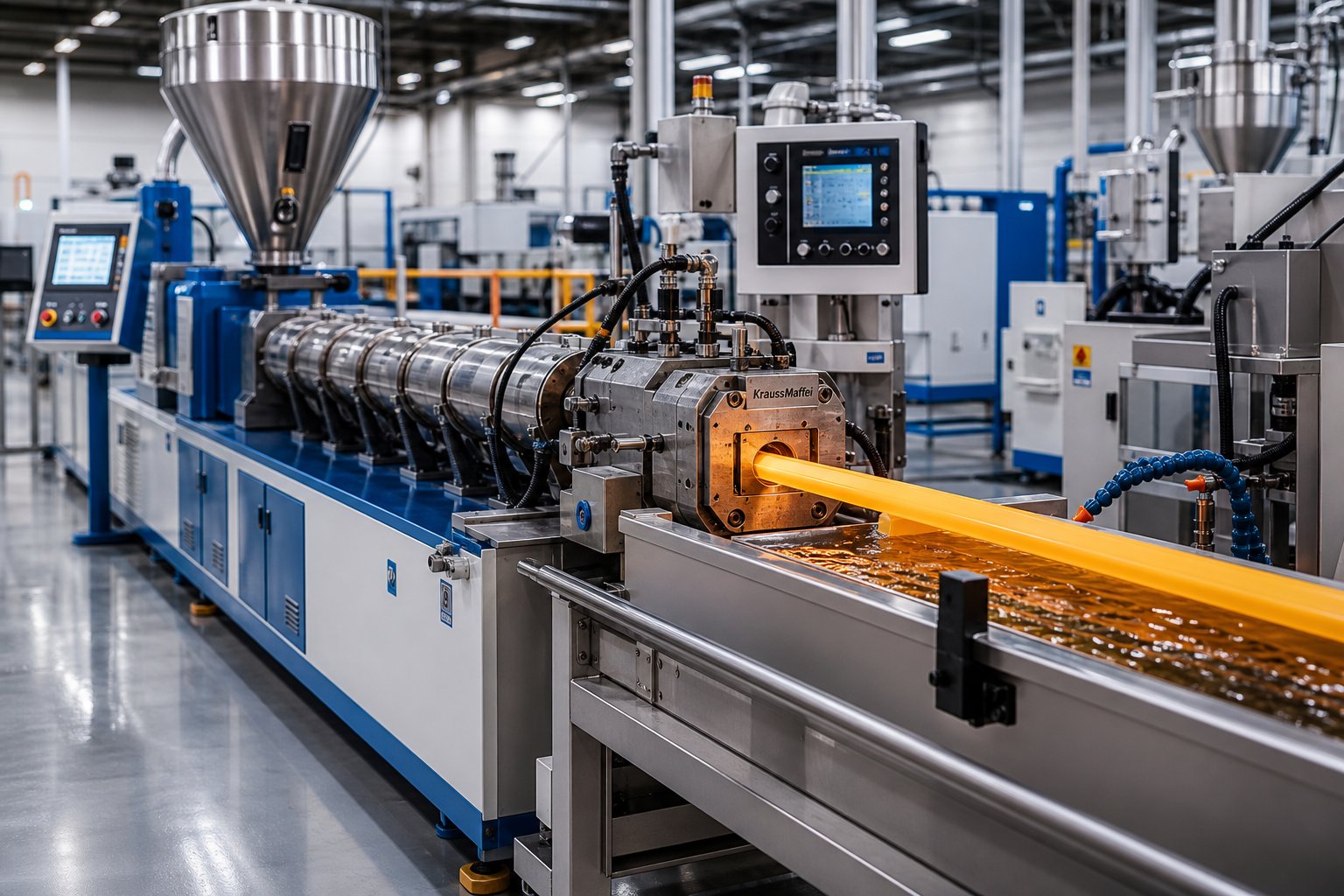
What Is Plastic Extrusion and How It Powers Modern Industry
Imagine a process that can turn a pile of raw plastic pellets into miles of perfectly shaped pipe, film, or trim — running continuously, hour after hour. That is exactly what plastic extrusion delivers, and it underpins an industry valued at $277.37 billion globally as of 2024, with projections exceeding $548 billion by 2035.
What Is Plastic Extrusion and Why Does It Matter
So, what is plastic extrusion? To define extrusion in its simplest terms:
Plastic extrusion is a high-volume manufacturing process in which thermoplastic raw material is melted and forced through a shaped die to produce a continuous profile with a uniform cross-section.
This definition for extrusion highlights what sets the method apart from discrete-part techniques like injection molding. Rather than filling a closed mold to create individual components, an extruder generates an uninterrupted length of product — pipes, sheets, films, tubing — that is cut or coiled downstream. The meaning extrusion carries in manufacturing is literally "to push out," and that mechanical principle has made plastics extrusion one of the most efficient ways to convert polymer resin into usable goods at scale.
With a compound annual growth rate of 6.4% forecasted through 2035, the process continues to gain ground as demand for lightweight, durable, and cost-effective plastic products accelerates worldwide.
Where Plastic Extrusion Fits in Modern Manufacturing
The reach of extruded products spans virtually every major sector:
- Construction — window profiles, vinyl siding, weatherstripping, and insulation panels
- Packaging — stretch films, shrink wraps, and thermoforming sheet stock
- Infrastructure — water pipes, gas conduit, and cable ducting
- Automotive — seals, edge trim, and under-hood tubing
- Medical — precision catheter tubing, IV lines, and respiratory components
- Electrical and electronics — wire insulation and protective sleeving
Packaging and building and construction alone account for the two largest application segments in the global extruded plastics market, driven by the need for lightweight yet durable material solutions. This breadth of application is precisely why understanding how extrusion works — from screw design to die geometry to downstream handling — gives engineers and procurement teams a tangible competitive edge.
This guide bridges that gap between introductory overviews and actionable engineering detail, walking you through every stage of the process, the equipment choices that matter, material selection strategies, and the troubleshooting knowledge that keeps production lines running efficiently.
How the Plastic Extrusion Process Works Step by Step
Every extruded product — whether it is a length of PVC pipe or a roll of stretch film — follows the same fundamental sequence. Raw polymer enters one end of an extrusion machine, and a continuous, dimensionally consistent profile exits the other. The magic is in the details of each stage, and understanding those details is what separates a stable, efficient plastic extrusion process from one plagued by scrap and downtime.
Here is the complete sequence at a glance:
- Material preparation and feeding
- Melting and metering inside the barrel
- Filtration through the breaker plate and screen pack
- Die shaping of the molten profile
- Cooling and calibration
- Haul-off, cutting, and collection
Each stage directly influences the quality of the finished product. Let's break them down.
Material Preparation and Feeding
Before a single pellet touches the screw, it needs to be properly prepared. Resin pellets, granules, or powders are loaded into a hopper mounted above the extruder machine feed throat. Sounds straightforward — but feeding consistency is one of the most underestimated variables in the entire extrusion process.
Two feeding approaches dominate:
- Volumetric feeding — delivers material based on a set volume per unit of time. It is simpler and less expensive but does not compensate for variations in pellet density or bulk flow characteristics.
- Gravimetric feeding — continuously weighs the material as it is dispensed, adjusting feed rate in real time. This method provides tighter control over throughput consistency, which is critical when blending virgin resin with colorants, additives, or recycled regrind.
Hygroscopic resins — materials like PET, polycarbonate, ABS, and nylon that absorb atmospheric moisture — require pre-drying before they enter the barrel. Internal moisture in these resins can cause voids, discoloration, and structural weakness in the finished extrudate. Drying also homogenizes material temperature, so the extruder receives a steady flow of resin at a consistent thermal starting point regardless of ambient seasonal conditions.
Melting and Metering Inside the Barrel
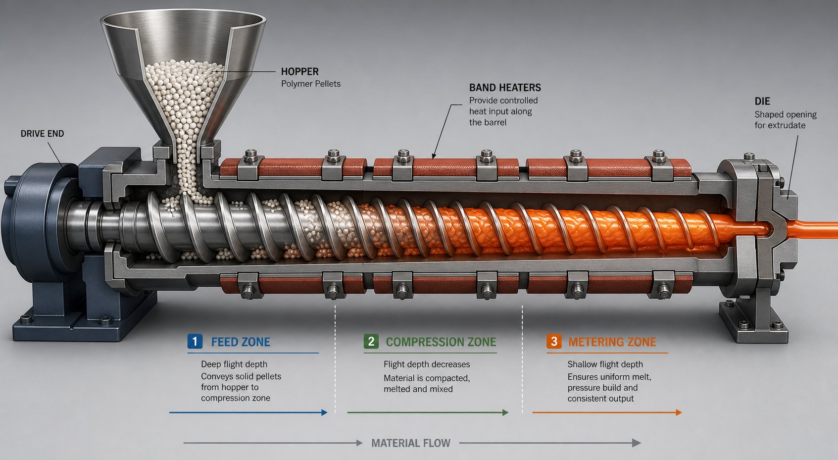
This is where the real transformation happens. The screw — rotating inside a heated barrel — performs three jobs simultaneously: conveying, melting, and pressurizing. It accomplishes this across distinct functional zones, each with specific screw geometry tailored to its task:
- Feed zone — the flight depth (the gap between the screw root and the barrel wall) remains constant and relatively deep. This zone accepts solid pellets from the hopper and moves them forward at a steady rate.
- Compression (transition) zone — here the flight depth progressively decreases, compacting the material and squeezing out trapped air. This compression initiates plasticization as the resin softens under combined heat and pressure.
- Metering zone — the flight depth is at its shallowest and remains constant. This zone's job is to deliver a homogeneous, fully molten polymer at consistent pressure and temperature to the die.
Two heat sources drive the melt. Resistance band heaters along the barrel supply external thermal energy, while viscous dissipation — the frictional heat generated by the screw shearing the polymer — provides a significant internal contribution. At low screw speeds, external heaters do most of the work; as speed increases, shear-generated heat becomes dominant, and the barrel heaters may actually switch to cooling mode to prevent overheating. Managing this balance is central to stable extrusion processing.
Screw geometry matters enormously. The compression ratio — the ratio of feed-zone flight depth to metering-zone flight depth — determines how aggressively the material is compacted. A typical compression ratio for polyolefins falls around 3:1 to 4:1, while amorphous resins like PVC may use a lower ratio closer to 2:1 to avoid excessive shear heating. The screw's length-to-diameter (L/D) ratio, commonly ranging from 24:1 to 36:1, governs residence time and the thoroughness of melting and mixing.
Die Shaping, Cooling, and Downstream Handling
Molten polymer leaving the metering zone first passes through a breaker plate and screen pack. The screen pack — layers of wire mesh — filters out contaminants and unmelted particles, while the breaker plate provides back-pressure that improves melt homogeneity and eliminates the rotational "memory" imparted by the screw.
From there, the melt enters the die, which shapes it into the target cross-section. Die design varies dramatically by product type — annular dies for pipe, flat dies for sheet and film, and complex profile dies for window frames or trim. The principle, though, is the same: the die's internal flow channels distribute the melt evenly so the extrudate exits with uniform wall thickness and geometry.
Cooling locks the shape in place. The method depends on the product:
- Water-bath immersion or vacuum cooling tanks — common for pipe and tubing, where vacuum helps hollow extrusions maintain internal dimensions while the polymer solidifies.
- Air-ring cooling — used in blown film extrusion to uniformly cool the expanding film bubble.
- Calibration sleeves and spray tanks — used for profiles and larger pipe to precisely control outer dimensions as the extrudate shrinks during cooling.
- Chill rolls — employed in cast film and sheet lines to rapidly quench the melt against polished, temperature-controlled rollers.
Downstream of cooling, a haul-off unit (puller) grips the extrudate and draws it through the entire plastic extrusion line at a carefully controlled speed. Even small variations in puller speed relative to extruder output can shift wall thickness or OD, so the master extrusion control synchronizes every element of the line in real time. Finally, the product reaches cutting, coiling, or stacking stations — the endpoint of a process that, when properly tuned, runs continuously for hours or even days with minimal operator intervention.
Getting each of these stages right is essential, but the extrusion line is only as good as its core component — the extruder itself. And the single biggest decision affecting extruder performance is the choice between single-screw and twin-screw configurations.
Single-Screw vs. Twin-Screw Extruders Compared
What is a plastic extruder, really? At its core, every extrusion extruder is a machine that melts polymer and pushes it through a die — but how that melting and pushing happens differs dramatically depending on whether one screw or two spins inside the barrel. This distinction shapes everything from product quality and throughput to capital investment and maintenance budgets. Yet many guides gloss over the comparison or reduce it to a single paragraph. Here, we break it down properly.
Single-Screw Extruder Design and Best Applications
If you had to pick the workhorse of the plastics industry, the single-screw plastic extruder machine would be it. Its design is elegantly simple: a single helical screw rotates inside a cylindrical barrel, relying on friction between the polymer and the barrel wall to drag material forward through the feed, compression, and metering zones discussed earlier.
That simplicity translates into tangible advantages — lower capital cost, straightforward operation, and reduced maintenance complexity. For processing pre-compounded, homogeneous resins into pipes, profiles, sheets, and blown film, a well-configured single-screw machine delivers reliable, high-volume output shift after shift.
Screw geometry is where the engineering nuance lives. The L/D ratio (length-to-diameter ratio) determines residence time and melting thoroughness — common values range from 24:1 for basic processing up to 36:1 or higher for applications demanding more intensive melting or mixing. The compression ratio controls how aggressively the material is compacted as flight depth decreases from the feed zone to the metering zone. Flight width, helix angle, and specialized mixing elements like Maddock or pineapple sections can be added to improve melt homogeneity for specific polymers. A screw optimized for HDPE pipe, for example, looks quite different from one designed for flexible PVC film — even if both fit the same barrel diameter.
So whats an extruder best suited for when it has a single screw? Think dedicated, continuous production of a consistent product using a single resin or a pre-blended compound. When the recipe is stable and the cross-section does not change, the single-screw platform is hard to beat on cost-per-kilogram economics.
Twin-Screw Extruder Advantages for Compounding and Specialty Processing
When the application demands intensive mixing, multiple additive streams, or processing of challenging feedstocks, twin-screw extruders step in. Two intermeshing screws rotate inside a figure-eight barrel bore, and their interaction creates fundamentally different material transport and mixing dynamics compared to single-screw machines.
Twin-screw extruders come in two primary configurations:
- Co-rotating — both screws turn in the same direction. This design generates high shear in the intermeshing zone, producing exceptional dispersive and distributive mixing. The screws are self-wiping, meaning material is continuously scraped from one screw to the other in an "infinity" pattern, which minimizes residence time and prevents localized degradation. Co-rotating machines dominate compounding, devolatilization, reactive extrusion, and masterbatch production.
- Counter-rotating — the screws turn in opposite directions, creating a positive-displacement "C-chamber" transport mechanism. Shear forces are lower, making this configuration ideal for heat-sensitive materials like rigid PVC. Counter-rotating extruders are widely used for PVC profile and pipe extrusion, and conical counter-rotating designs are common in window-frame production lines.
The modular barrel and screw-element design of most twin-screw platforms is another major differentiator. Conveying elements, kneading blocks, reverse-flight elements, and mixing discs can be arranged in virtually unlimited combinations along the shaft, letting process engineers tailor the screw profile to a specific recipe or operation — whether that is incorporating glass fibers into nylon, dispersing nano-fillers into a masterbatch, or processing wood-plastic composite (WPC) formulations where moisture removal and uniform fiber distribution are critical.
This versatility makes twin-screw machines the preferred extruder for polymer compounding tasks, but it comes at a price: higher capital investment, more complex gearboxes, tighter manufacturing tolerances on the intermeshing screws, and a steeper learning curve for operators.
Choosing the Right Screw Configuration for Your Application
Selecting between single-screw and twin-screw platforms is not about which machine is "better" — it is about matching the extruder's capabilities to your product requirements, material characteristics, and production economics. The table below maps the key decision criteria side by side:
| Criteria | Single-Screw Extruder | Twin-Screw Extruder |
|---|---|---|
| Mixing capability | Adequate for pre-compounded resins; limited dispersive mixing without specialized screw elements | Excellent dispersive and distributive mixing; ideal for compounding and additive incorporation |
| Throughput range | Wide range; high output on dedicated product lines | Wide range; throughput depends on screw diameter and L/D ratio |
| Material versatility | Best with pellets and pre-compounded materials; limited with powders or highly filled systems | Handles pellets, powders, fibers, liquids, and high-filler-loading formulations |
| Capital cost | Lower initial investment | Higher initial investment due to complex gearbox and precision screw manufacturing |
| Maintenance complexity | Simpler; fewer wear components | More complex; modular screw elements and tight tolerances require skilled maintenance |
| Typical applications | Pipe, profile, film, sheet, wire coating, and monofilament extrusion | Compounding, masterbatch, reactive extrusion, devolatilization, WPC, and recycling of mixed plastics |
Regardless of which platform you choose, one component exerts more influence on output quality than any other: the screw barrel assembly. Its metallurgy determines resistance to abrasive fillers and corrosive additives. Its dimensional precision — bore straightness, concentricity, and surface finish — directly controls melt uniformity, pressure consistency, and energy efficiency. Industry data suggests that roughly 25% of extrusion failures trace back to premature barrel wear, making the screw barrel a component that deserves careful specification and proactive replacement rather than run-to-failure management.
For teams evaluating replacement screw barrels or exploring custom screw-barrel configurations — whether for a single-screw pipe line or a twin-screw compounding platform — working with a specialist supplier makes a measurable difference. NANHAIYA, for example, provides application-specific screw barrel solutions across pipe, profile, film, sheet, WPC, and granulation equipment, combining metallurgical expertise with practical processing knowledge that helps extrusion teams match component specifications to real-world production demands.
What are extruders without the right materials running through them? The screw and barrel configuration only tells half the story — the other half is the polymer you feed into the machine and the additives you blend with it.
Extrusion Materials and Additives Selection Guide
Choosing the right resin is arguably the most consequential decision in any extrusion project. The polymer dictates processing temperatures, mechanical performance, chemical resistance, regulatory compliance, and even the screw geometry required to run it efficiently. Yet many resources treat material selection as an afterthought. Here, we lay out a practical guide to the most common plastic extrusion materials, the additives that tailor their performance, and the sustainability considerations reshaping feedstock strategies.
Common Extrusion-Grade Resins and Their Properties
Not all plastics behave the same way inside a barrel, and not all end-use environments demand the same properties. The polymer extrusion process works with a broad family of thermoplastics, but a handful of extrusion grade polymers account for the vast majority of global output. Understanding each resin's processing window, strengths, and limitations helps you match the material to your application — rather than forcing a compromise.
PVC extrusion alone represents one of the largest single-resin segments in the industry. Rigid PVC (uPVC) dominates pipe, conduit, and window-profile production thanks to its excellent chemical resistance, flame retardancy, and low cost. Flexible PVC, softened with plasticizers, serves cable jacketing, medical tubing, and gasket applications. Processing temperatures for PVC typically fall between 160 and 200 degrees Celsius, and the resin's heat sensitivity demands careful thermal management to avoid degradation.
Polyethylene — in its HDPE, LDPE, and LLDPE variants — is the other heavyweight. Extruded polyethylene products range from large-diameter water mains and gas pipes (HDPE) to packaging films and agricultural sheeting (LDPE and LLDPE). These polyolefins process at relatively low temperatures and offer outstanding chemical resistance, though UV stability typically requires additive protection for outdoor applications.
Polypropylene brings higher stiffness and a superior temperature ceiling compared to PE, making it a strong choice for thermoforming sheet, strapping, and fiber extrusion. ABS and polycarbonate serve applications requiring impact resistance and optical clarity, respectively, though both are hygroscopic and demand thorough pre-drying. Polystyrene rounds out the commodity range with easy processability for foam sheet and rigid packaging.
The table below maps key properties and typical extruded products for each resin family:
| Resin | Processing Temp Range | Chemical Resistance | UV Stability | Mechanical Strength | Food-Contact Suitability | Typical Extruded Products |
|---|---|---|---|---|---|---|
| PVC (rigid) | 160–200 °C | Excellent (acids, bases) | Good with stabilizers | High rigidity | Yes (specific grades) | Pipe, conduit, window profiles, siding |
| PVC (flexible) | 150–190 °C | Good | Moderate | Flexible, moderate tensile | Yes (medical/food grades) | Cable jacketing, medical tubing, gaskets |
| HDPE | 180–230 °C | Excellent | Low (needs UV stabilizer) | High tensile, good impact | Yes | Water/gas pipe, bottles, sheet |
| LDPE | 160–200 °C | Good | Low | Flexible, lower tensile | Yes | Packaging film, shrink wrap, squeeze tubes |
| LLDPE | 170–210 °C | Good | Low | High elongation, puncture resistant | Yes | Stretch film, agricultural film, liners |
| PP | 200–250 °C | Very good | Moderate (needs stabilizer) | High stiffness, good fatigue | Yes | Thermoform sheet, strapping, fibers |
| ABS | 200–250 °C | Moderate | Low | Excellent impact | Specific grades only | Trim, edge banding, appliance housings |
| Polycarbonate | 280–320 °C | Moderate | Moderate (coated grades) | Very high impact, optical clarity | Specific grades only | Sheet, glazing panels, light covers |
| Polystyrene | 180–240 °C | Low (solvent sensitive) | Low | Rigid but brittle (GPPS); improved impact (HIPS) | Yes (GPPS food grades) | Foam sheet, food trays, packaging |
Temperature data here reflects typical extrusion barrel profiles rather than raw melting points — actual settings vary with screw speed, die geometry, and specific resin grade. When in doubt, always consult the resin manufacturer's processing datasheet for your exact grade.
Additives and Compounding for Tailored Performance
Rarely does a raw polymer go straight from pellet to finished product without some form of modification. Additives are integral to virtually every commercial plastic formulation, adjusting properties that the base resin alone cannot deliver.
Here are the most common additive categories in thermoplastic extrusion and what each one does:
- Colorants — delivered as masterbatch (pre-dispersed pigment in a carrier resin) or dry-blended powder. Masterbatch provides more consistent color dispersion and is the preferred method for most extrusion lines, while dry blending suits lower-volume or cost-sensitive runs.
- UV stabilizers — essential for any product exposed to sunlight. Polyolefins and polypropylene degrade rapidly under UV radiation without stabilization, leading to chalking, embrittlement, and color fade.
- Flame retardants — halogenated compounds, aluminum trihydrate, and phosphorus-based systems reduce flammability. PVC contains inherent flame resistance from its chlorine content, but other resins require additive protection to meet building codes and electrical safety standards.
- Mineral fillers — calcium carbonate (CaCO3) and talc are the most widely used. CaCO3 reduces resin cost and improves stiffness, while talc enhances nucleation in polypropylene, increasing crystallization rate and heat-deflection temperature.
- Plasticizers — primarily used in flexible PVC to lower the glass transition temperature and produce soft, pliable products. Phthalate-based plasticizers have historically dominated, though non-phthalate alternatives are gaining share driven by regulatory pressure.
- Impact modifiers — elastomeric additives like acrylic impact modifiers or chlorinated polyethylene (CPE) improve toughness, particularly in rigid PVC and polystyrene formulations that would otherwise be brittle at low temperatures.
Compounding is the process of melt-blending these additives into the base resin to create a homogeneous, ready-to-extrude material. Twin-screw extruders are the standard platform for compounding, as their superior mixing capability ensures uniform dispersion of fillers, fibers, and liquid additives — a task that exceeds the mixing limits of most single-screw designs. The result is a pelletized compound that can be fed directly into a production extruder, simplifying downstream processing and improving batch-to-batch consistency.
Sustainability and Recycled Material Considerations
The extrusion materials landscape is shifting. Regulatory mandates, brand commitments, and consumer demand are accelerating the adoption of recycled and bio-based feedstocks — and the polymer extrusion process must adapt accordingly.
Post-consumer recycled (PCR) and post-industrial recycled (PIR) resins now represent a fast-growing share of extrusion feedstock. PIR material — factory trimmings, startup scrap, and off-spec production — generally offers cleaner, more consistent quality because it has not been contaminated through consumer use. PCR feedstock, by contrast, introduces several processing challenges:
- Contamination — residual labels, adhesives, and mixed polymer types can cause gels, specks, and screen-pack buildup during extrusion.
- Melt-flow variability — each recycling cycle can shorten polymer chains, reducing viscosity and mechanical properties. Monitoring melt flow index on every incoming lot is essential.
- Odor — organic residues trapped in PCR flake can produce off-odors during processing, limiting suitability for food-contact or indoor applications without additional treatment.
Proper screw design and filtration go a long way toward mitigating these issues. Fine-mesh screen packs catch particulate contaminants, while screws with enhanced mixing sections improve melt homogeneity despite batch-to-batch variation in recycled feedstock. Devolatilization zones on twin-screw compounders can extract moisture and volatile organic compounds before the melt reaches the die.
Beyond recycled conventional polymers, bio-based and biodegradable resins like PLA (polylactic acid) and PHA (polyhydroxyalkanoates) are entering the extrusion market. PLA processes at 150 to 180 degrees Celsius but is extremely heat-sensitive — minimizing barrel residence time is critical to preserving molecular weight and avoiding brittleness. PHA offers biodegradability in a wider range of environments but has a narrower processing window that demands precise temperature control.
Whether you are running virgin polyolefins, engineering thermoplastics, or recycled blends, material selection is never just about the resin itself — it is about the entire system: screw design, additive package, filtration strategy, and downstream cooling. That system-level perspective becomes even more important when you consider the sheer diversity of products that thermoplastic extrusion produces, from massive infrastructure pipes to sub-millimeter medical tubing.
Types of Extruded Plastic Products and Applications
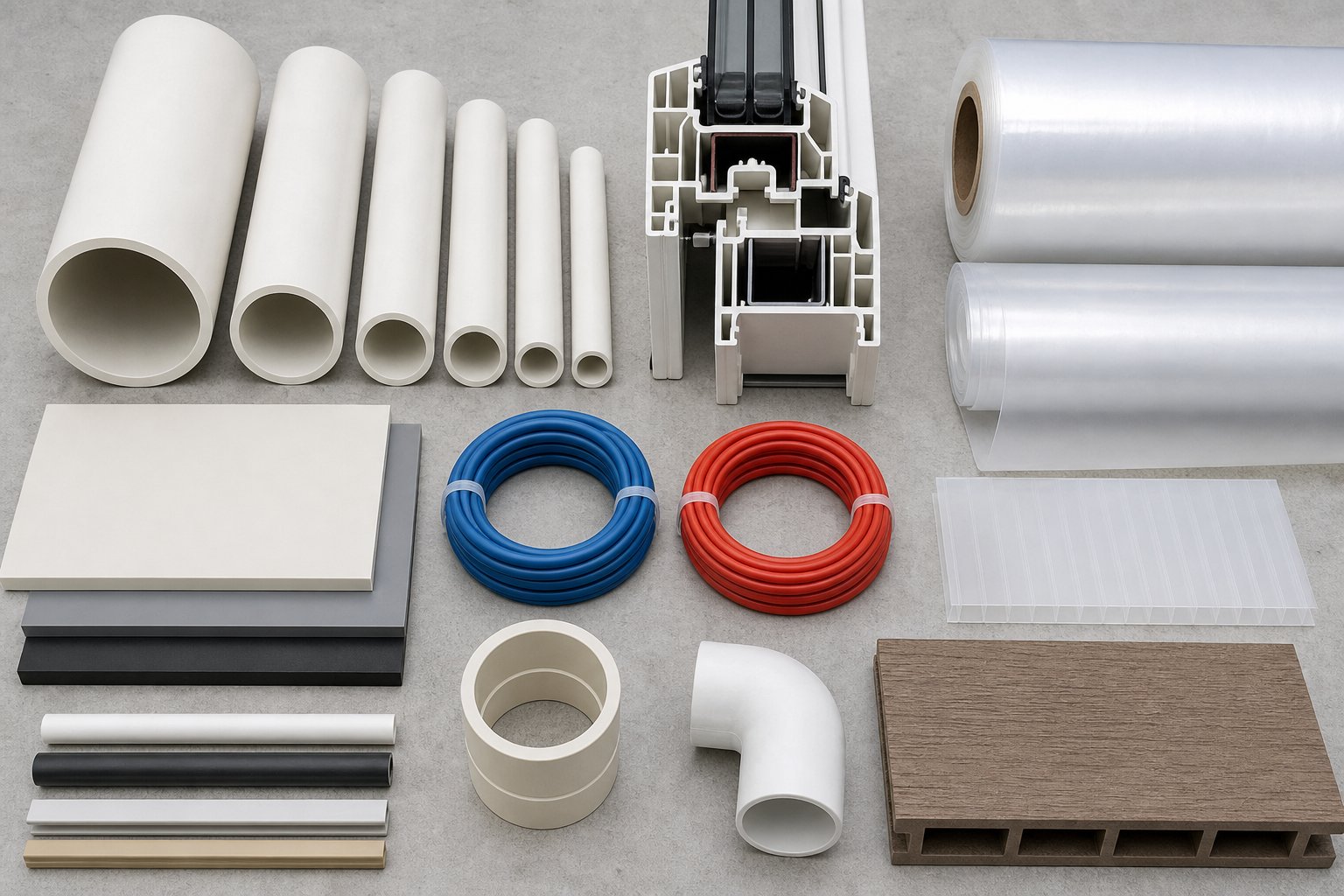
That diversity is not an exaggeration. A single manufacturing principle — melt polymer, push it through a shaped die, cool it — generates product families that look nothing alike and serve entirely different markets. The differences come down to die geometry, downstream equipment, and cooling strategy. Let's walk through the major categories.
Pipe and Tubing Extrusion
Pipe extrusion ranks among the highest-volume outputs in the entire plastics industry. The product range is enormous: large-diameter HDPE water mains exceeding 1,200 mm, PVC sewer and drainage pipe, PE gas distribution lines, corrugated conduit for electrical infrastructure, and extruded plastic tubing as small as a fraction of a millimeter for medical catheters and IV lines.
All pipe and tube extrusion relies on an annular die — essentially a ring-shaped opening that forms the hollow cross-section. Inside the die, a mandrel creates the bore while the outer die body defines the outside diameter. Achieving uniform wall thickness requires precise centering of the mandrel, because even a slight offset produces a thick side and a thin side that no amount of downstream correction can fully fix.
Downstream of the die, vacuum sizing stabilizes the pipe's outside diameter by drawing the still-soft extrudate against a calibration sleeve while cooling water removes heat. The haul-off puller then draws the pipe through the line at a controlled rate — and the balance between melt output and puller speed directly governs wall thickness. Even small fluctuations in that draw balance show up as dimensional drift. Tube extrusion for medical applications adds another layer of precision, often requiring laser micrometers for inline OD and wall measurement at tolerances below +/- 0.025 mm.
Profile Extrusion for Complex Cross-Sections
Imagine a window frame cross-section: multiple hollow chambers, thin walls, snap-fit features, and gasket grooves — all produced in a single continuous pass. That is the domain of profile extrusion, and it represents some of the most technically demanding work in the extrusion of pipes and profiles.
Plastic extrusion profiles include vinyl window and door frames, edge trim for furniture and automotive, weatherstripping, deck boards, cable channels, and thousands of custom industrial shapes. Extruded plastic profiles differ from pipe in a critical way: their cross-sections are rarely symmetrical. This asymmetry creates uneven melt flow velocities across the die exit, which can cause distortion, warping, or dimensional deviation if not carefully managed.
Research into simulation-based die design has shown that non-uniform polymer flow at the die exit is inevitable in complex profiles. Designers must compensate by adjusting land lengths, flow-restriction channels, and exit geometry — traditionally through trial and error, though computational tools are narrowing that gap. Differential cooling is equally important: thicker sections cool more slowly than thin walls, and without calibration tooling that applies cooling and vacuum precisely where needed, the profile can bow or twist as internal stresses develop unevenly.
Film and Sheet Extrusion
Film and sheet extrusion splits into two fundamentally different processes based on die type and cooling method:
- Blown film — molten polymer exits a tubular (annular) die and is inflated into a bubble by internal air pressure. An air ring cools the bubble externally, and the biaxial stretching during inflation gives blown extruded films superior mechanical strength and flexibility compared to cast alternatives. Applications include stretch wrap, agricultural mulch film, heavy-duty bags, and multi-layer barrier packaging.
- Cast film and sheet extrusion — a flat die deposits molten polymer onto chilled, polished rollers that rapidly quench the melt. This sheet extrusion method produces films with excellent clarity, gloss, and thickness uniformity, making it the preferred route for thermoforming sheet stock, signage panels, and medical packaging where optical properties matter.
Here is a quick-scan list of the major product categories and where they show up:
- Packaging films — food wrap, pallet stretch film, shrink sleeves, and stand-up pouch laminates
- Agricultural films — greenhouse covers, silage wrap, and mulch film
- Thermoforming sheet — trays, clamshells, cups, and blister packs formed from extruded sheet stock
- Signage and display sheet — acrylic, polycarbonate, and PVC sheet for retail and architectural applications
- Specialty outputs — WPC (wood-plastic composite) decking and fencing, coextruded multi-layer films with barrier layers like EVOH, and cable jacketing where concentric coating of conductors requires precision crosshead dies
Each of these product families pushes the same core process in different directions — different dies, different cooling strategies, different downstream equipment. Yet they all share one thing: regardless of the product, the extruder must deliver a consistent, homogeneous melt at stable pressure and temperature. That consistency is exactly what makes the comparison between extrusion and other plastic manufacturing methods so instructive — because where extrusion excels and where it falls short depends entirely on how well its continuous-profile nature matches the product requirement.
Plastic Extrusion vs. Other Manufacturing Methods
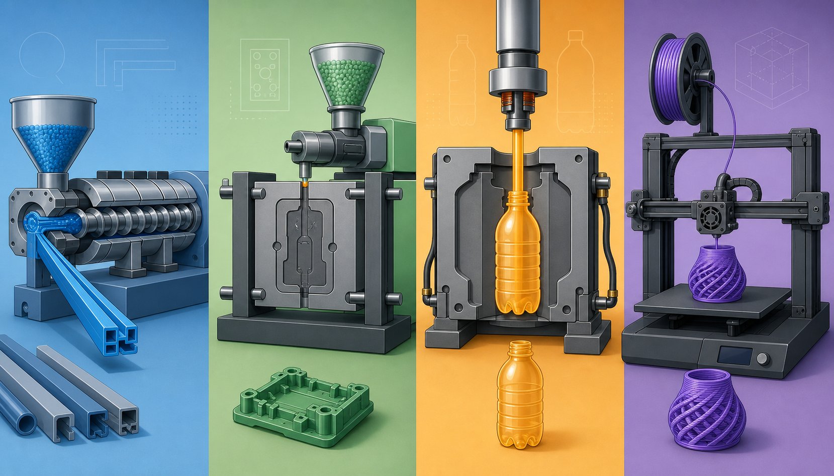
How do you decide whether extrusion is the right plastic processing method for your product — or whether injection molding, blow molding, thermoforming, or even 3D printing would serve you better? The answer hinges on a handful of practical criteria: part geometry, production volume, tooling budget, and lead-time constraints. Yet structured, side-by-side comparisons are surprisingly rare in technical resources. Let's fix that.
Extrusion vs. Injection Molding
This is the comparison most engineers encounter first, and the distinction is fundamental. The extrusion manufacturing process produces continuous profiles with a uniform cross-section — pipe, tubing, sheet, film, trim — running in theoretically endless lengths. Injection molding, by contrast, fills a closed mold cavity to create discrete three-dimensional parts with complex geometries, undercuts, and variable wall features that extrusion simply cannot achieve.
The cost implications follow directly from that geometry difference. Extrusion dies are comparatively simple steel tools; tooling costs for extrusion can be 80% to 90% lower than injection mold tooling, which requires precision CNC-machined cavities, cooling channels, and ejection systems. For a startup or a product team prototyping a new profile, that tooling gap alone can determine which process is financially viable.
Per-unit economics tell a more nuanced story. Injection molding amortizes its higher upfront mold cost across hundreds of thousands — sometimes millions — of identical parts, driving the piece price down aggressively at volume. Extrusion moulding keeps per-meter costs moderate across all volumes because the die cost is already low, but it cannot match injection molding's rock-bottom unit price on small, discrete components at very high quantities. The decision framework is straightforward: if your product has a constant cross-section and is needed in continuous or long lengths, extrusion wins. If it requires three-dimensional complexity in a discrete part, injection molding is the clear choice.
Extrusion vs. Blow Molding and Thermoforming
Blow molding and thermoforming solve different problems, and both have an interesting relationship with extrusion — they often depend on it as an upstream process.
Blow molding creates hollow containers — bottles, tanks, automotive ducts — by inflating a heated plastic preform (called a parison) inside a two-part mold. In extrusion blow molding, that parison is itself an extruded tube, which means the extrusion of plastics is literally the first step of the blow-molding workflow. The process excels at producing thin-walled, hollow shapes that would be difficult or impossible to mold as solid injection-molded parts. Tooling costs are lower than injection molding, though dimensional precision is also lower, and flash trimming is typically required.
Thermoforming takes a heated plastic sheet — often produced by sheet plastic extrusion — and drapes or vacuum-draws it over a mold to create trays, clamshells, enclosures, and packaging. Because the mold is single-sided and often made from aluminum rather than hardened steel, tooling costs fall well below injection molding. Thermoforming works best for large, shallow parts with moderate detail, and it relies entirely on the quality of the extruded sheet feeding it. Thickness uniformity, surface finish, and consistent melt properties in the incoming sheet all determine the quality of the thermoformed part downstream.
In both cases, extrusion is not competing with these methods — it is enabling them. Recognizing this upstream-downstream relationship helps teams plan integrated production strategies rather than viewing each process in isolation.
Extrusion vs. 3D Printing for Prototyping and Production
Here is a connection many people overlook: the most common desktop 3D printing technology — Fused Deposition Modeling (FDM), also called Fused Filament Fabrication (FFF) — is itself a miniature extrusion process. A thermoplastic filament is melted and extruded through a small nozzle, depositing material layer by layer to build a three-dimensional object. So in a real sense, 3D printing borrowed its core mechanism from extrusion manufacturing.
The similarities end there. Industrial extrusion molding lines run continuously at throughputs measured in hundreds of kilograms per hour; a 3D printer deposits grams per hour. Material costs per kilogram are dramatically lower for extrusion-grade pellets than for specialty 3D printing filaments. And mechanical properties of extruded parts — produced from a fully homogeneous melt — generally exceed those of layer-by-layer printed parts, where interlayer adhesion can be a structural weak point.
Where 3D printing holds a decisive advantage is design freedom and setup speed. Complex internal cavities, lattice structures, and organic geometries that no die could produce are routine for additive manufacturing. There is zero tooling cost, making it ideal for one-off prototypes, custom medical devices, or small batches where unit cost is secondary to speed and customization. Many manufacturers today use 3D printing for early-stage prototyping and then transition to extrusion for full-scale production — combining the strengths of both technologies.
Side-by-Side Process Comparison
The table below consolidates the key decision criteria across all five methods. Use it as a quick-reference guide when evaluating which process fits your next project:
| Criteria | Plastic Extrusion | Injection Molding | Blow Molding | Thermoforming | 3D Printing (FDM/FFF) |
|---|---|---|---|---|---|
| Part geometry | Continuous, uniform cross-section (2D profile) | Complex 3D discrete parts with undercuts, variable walls | Hollow, thin-walled containers and ducts | Large, shallow to moderate-depth shapes from sheet | Virtually unlimited 3D geometry, including internal features |
| Tooling cost | Low (simple steel die) | High (precision CNC-machined mold with cooling and ejection) | Moderate (two-part mold, simpler than injection) | Low to moderate (single-sided aluminum or composite mold) | None (digital file only) |
| Per-unit cost at volume | Low (continuous output amortizes quickly) | Very low at high volume (mold cost spread across millions of parts) | Low to moderate | Moderate (sheet cost plus forming) | High (slow layer-by-layer deposition, expensive filament) |
| Material options | Wide range of thermoplastics (PE, PP, PVC, ABS, PC, PS, and more) | Very wide (thermoplastics, thermosets, filled and reinforced grades) | PE, PP, PET, PVC (primarily polyolefins) | PS, PP, PET, ABS, HDPE, PVC sheet | PLA, ABS, PETG, nylon, TPU; growing but still limited |
| Lead time | Short (die fabrication in days to weeks) | Long (mold design and machining: weeks to months) | Moderate (mold fabrication simpler than injection) | Short to moderate (simple mold, fast setup) | Very short (print from digital file in hours) |
| Production volume sweet spot | Medium to very high (continuous runs) | High to very high (thousands to millions of parts) | Medium to high | Low to medium (prototyping through moderate runs) | One-off to low (prototypes, custom parts, small batches) |
| Best-fit applications | Pipe, tubing, profiles, film, sheet, wire coating, decking | Housings, caps, connectors, gears, medical devices, consumer products | Bottles, tanks, automotive ducts, containers | Trays, clamshells, enclosures, signage, vehicle interior panels | Prototypes, custom jigs, short-run end-use parts, medical models |
No single process dominates every scenario. The real skill lies in matching the method to the product's geometry, volume, budget, and timeline — and recognizing where processes complement each other rather than compete. Extrusion feeds sheet to thermoforming lines, produces parisons for blow molders, and even supplies the filament that 3D printers consume. That interconnectedness is one reason extrusion manufacturing holds such a central position in the broader plastics ecosystem.
Understanding where plastic extrusion fits relative to its alternatives naturally raises the next question: what specific strengths should you lean into, and what limitations should you design around?
Advantages and Disadvantages of Plastic Extrusion
Every manufacturing method involves trade-offs, and plastic extrusion is no exception. Its strengths are substantial — there is a reason the process accounts for such a large share of global thermoplastic output — but its limitations are equally real and worth understanding before you commit tooling budgets or design resources. A clear-eyed look at both sides helps you decide whether extruded plastic products are the right fit for your application or whether an alternative process would serve you better.
Key Advantages of the Extrusion Process
The benefits of extruding plastic into continuous profiles are hard to match with any other single method:
- High production rates — once a line is running, extruded plastics flow continuously for hours or even days, delivering output rates measured in hundreds of kilograms per hour on standard equipment.
- Low tooling cost — extrusion dies are far simpler and less expensive than injection molds. Where a complex injection mold might cost tens of thousands of dollars, a profile die often ranges from a few hundred to a few thousand, making the process accessible for smaller production runs and new product introductions.
- Excellent material efficiency — scrap generated during startup, shutdown, or color changeovers can often be reground and re-extruded, keeping waste rates well below those of most discrete-part processes.
- Continuous and long-length capability — no other plastics process matches extrusion's ability to produce uninterrupted lengths of product. Pipe, tubing, and cable jacketing can be manufactured in coils or straight lengths limited only by handling logistics.
- Wide cross-sectional variety — from simple round tubing to multi-chamber window profiles, the range of achievable shapes is broad. Custom dies can produce virtually any constant cross-section a designer can specify.
- Rigid and flexible material compatibility — the same fundamental process handles everything from stiff PVC conduit to soft TPE seals, simply by changing the resin and adjusting processing parameters.
- Low per-unit cost at volume — combined with continuous operation and minimal tooling amortization, plastic extrusions deliver compelling economics at medium to high volumes.
Limitations and Design Constraints to Consider
Balanced against those strengths, the process carries inherent constraints that every product designer and engineer should factor in early:
- Constant cross-section only — extruded plastic maintains the same profile along its entire length. If your design requires three-dimensional geometry changes, undercuts, or variable wall features, extrusion cannot deliver them without secondary operations.
- Broader dimensional tolerances — typical extrusion tolerances range from +/- 0.5 mm to +/- 1.5 mm, significantly wider than injection molding's +/- 0.1 mm to +/- 0.5 mm capability. Tight-tolerance applications may require post-extrusion machining or alternative processes.
- Die swell and shrinkage compensation — molten polymer expands as it exits the die and then contracts during cooling. Both phenomena must be anticipated in die design and downstream calibration, adding complexity to new product development.
- Surface finish dependence — the quality of the extruded surface is directly tied to die condition, melt temperature, and polymer cleanliness. Worn or damaged dies produce drag marks and streaks that cannot be corrected without stopping the line.
- Wall-thickness uniformity challenges — complex, asymmetrical profiles are particularly prone to uneven wall distribution. Achieving consistent thickness across all sections of an intricate profile requires careful die balancing and differential cooling — skills that blend art with engineering.
- Material changeover scrap — switching resins or colors requires purging the barrel, screw, and die of residual material. Depending on the resin and the color transition, purge scrap can represent a meaningful material and time cost.
When Extrusion Is the Right Choice
With advantages and limitations laid out side by side, the decision framework comes into focus. Plastic extrusion excels when your product meets these criteria:
Choose extrusion when the product has a consistent cross-section, is needed in continuous or long lengths, demands medium-to-high production volume, and when tooling budget is constrained relative to injection molding alternatives.
If your application checks most of those boxes, extrusion almost certainly offers the best combination of cost, speed, and material efficiency. If it does not — particularly if the part requires variable geometry or sub-millimeter precision across complex features — injection molding, machining, or thermoforming may be a better path.
Of course, knowing that extrusion is the right process is only the starting point. Translating a product concept into a manufacturable extruded profile — and keeping it running at quality once production begins — requires a working knowledge of design-for-extrusion principles and the defects that derail even well-planned lines.
Design Guidelines and Troubleshooting for Extruded Parts
A well-chosen process and the right resin only get you halfway. The difference between a plastic extrusion profile that runs smoothly on the first attempt and one that triggers weeks of die revisions and scrap usually comes down to how well the part was designed for the process — and how quickly the production team can diagnose problems when they inevitably appear. This section bridges both disciplines: designing extruded plastic shapes that cooperate with the physics of melt flow, and systematically resolving defects that threaten output quality.
Design Guidelines for Extruded Profiles
Designing for plastic profile extrusion is not the same as designing for machining or injection molding. The polymer is semi-molten as it exits the die, still soft enough to sag, warp, or distort before cooling locks its shape. Every design decision either simplifies or complicates that critical transition from liquid to solid. Here are the principles that experienced profile engineers follow:
- Maintain uniform wall thickness — this is the single most impactful guideline. Thick sections cool more slowly than thin ones, creating differential shrinkage that pulls the profile out of shape. Where thickness changes are unavoidable, taper transitions gradually rather than stepping abruptly. A ratio of no more than 3:1 between the thickest and thinnest walls in a cross-section is a practical ceiling for most resins.
- Use generous corner radii — sharp internal corners concentrate stress in the finished part and create flow dead zones inside the die where polymer can stagnate and degrade. A minimum internal radius of 0.5 mm to 1.0 mm is standard; larger is always better. External corners benefit from radii as well, both for flow uniformity and for reducing die-manufacturing complexity.
- Design symmetrical cross-sections when possible — a symmetrical plastic extrusion profile cools evenly from all sides, which simplifies die balancing and reduces warpage. Asymmetric profiles are certainly achievable — window frames are proof of that — but each axis of asymmetry adds calibration and cooling complexity that increases development time and cost.
- Understand hollow vs. solid trade-offs — hollow profiles save material and reduce weight, but they require internal mandrels or bridge supports inside the die, increasing die cost and complicating melt-flow distribution. Multi-chamber hollow profiles, like those used in window and door systems, demand sophisticated die design and vacuum calibration to maintain internal geometry.
- Account for die swell and shrinkage — the extrudate expands as it exits the die (die swell) and then contracts as it cools (thermal shrinkage). Both effects vary by resin: polyolefins exhibit more shrinkage than PVC, for example. Die openings must be oversized and shaped to compensate, which is why profile extrusion plastic die design is as much iterative craft as upfront calculation.
- Keep achievable tolerances in perspective — standard extrusion tolerances fall in the range of +/- 0.5 mm to +/- 1.5 mm for most commercial profiles. Precision extrusion for medical tubing or tight-fit seals can push tighter, but doing so requires more sophisticated calibration tooling, inline measurement, and slower line speeds.
The overarching principle is straightforward: designing for extrusion from the outset avoids costly die revisions, extended trial runs, and compromised part performance. A conversation between the product designer and the die maker before steel is cut pays for itself many times over.
Common Extrusion Defects and Troubleshooting
Even a well-designed profile on a well-maintained line will occasionally produce defects. The key is recognizing what you are seeing, understanding why it is happening, and knowing which parameter to adjust. The table below covers the most common issues that production teams encounter, drawn from industry troubleshooting practice:
| Defect | Likely Cause | Recommended Fix |
|---|---|---|
| Melt fracture (shark skin) | Excessive shear stress at the die exit; melt temperature too high or too low for the resin; screw speed too high | Reduce screw speed; adjust melt temperature to the resin's optimal processing window; add processing aids (lubricants or slip agents) to reduce surface shear; polish die land surfaces |
| Die lines (streaks) | Damaged or contaminated die lip; buildup of degraded resin on die surfaces; scratched die land | Clean and re-polish die surfaces; inspect for nicks or corrosion; increase screen-pack filtration to catch contaminants before they reach the die |
| Voids and bubbles | Moisture in the resin (especially hygroscopic materials); insufficient venting; trapped air in the feed zone | Ensure thorough pre-drying to the resin supplier's specifications; verify vent port operation on vented-barrel extruders; check hopper and feed-throat seals |
| Warpage or bowing | Uneven cooling rates across the profile cross-section; asymmetric die flow; residual stress from non-uniform wall thickness | Rebalance cooling — adjust water-spray zones, calibration-sleeve contact, or air flow to equalize cooling on all sides; review die land lengths for flow uniformity; redesign wall-thickness transitions |
| Uneven wall thickness | Off-center mandrel in pipe dies; unbalanced flow channels in profile dies; inconsistent haul-off speed | Re-center mandrel; adjust die bolts or flow restrictors to rebalance melt distribution; calibrate haul-off speed against extruder output |
| Surface discoloration or yellowing | Thermal degradation from excessive melt temperature or residence time; contaminated regrind; inadequate heat stabilizers | Reduce barrel temperatures; lower screw speed to decrease shear heating; verify regrind quality; confirm stabilizer loading in the formulation |
| Degradation (black specks, gels) | Stagnant melt zones in the die or adapter; excessive residence time; contaminated screen pack or barrel | Streamline die flow paths to eliminate dead spots; purge thoroughly between material changes; replace worn screen packs; inspect screw flights for hang-up areas |
Notice a pattern? Many root causes trace back to the same handful of variables — melt temperature, shear rate, resin moisture, and die condition. Systematic troubleshooting means checking these fundamentals first before chasing more exotic explanations. Keeping a log of process parameters alongside defect observations accelerates root-cause analysis on repeat issues.
Quality Control and Inspection Methods
Catching defects after they have ruined a production run is expensive. Modern extrusion technologies make it possible to detect dimensional drift and surface anomalies in real time, allowing operators to correct problems before scrap accumulates.
Inline measurement provides the fastest feedback loop:
- Laser micrometers — shadow-based systems positioned after the cooling section measure outside diameter, inside diameter, and ovality at rates up to 12,000 measurements per second with repeatability as tight as +/- 0.000005 inches. Triple-axis configurations capture dimensional data on multiple planes simultaneously, catching out-of-round conditions that a single-axis gauge would miss.
- Ultrasonic wall-thickness gauges — typically positioned in the quench tank, these systems use arrays of 4 or 8 ultrasonic transducers to measure wall thickness and concentricity around the full circumference. They can resolve wall thickness to +/- 0.001 inches, making them essential for medical tubing and other precision extrusion applications where concentricity specifications are tight.
- Closed-loop control — advanced lines connect inline gauges directly to the extruder and haul-off control systems. When the laser micrometer detects a diameter trending toward the upper specification limit, the software automatically adjusts puller speed, air pressure, or screw RPM to bring it back. This closed-loop approach can bring a line into specification within minutes of startup, compared to the 15 to 30 minutes of manual adjustment that experienced operators typically need.
Offline testing complements inline monitoring for properties that cannot be measured on a moving product:
- Dimensional inspection — cross-sections are cut and measured against the profile drawing using optical comparators, coordinate measuring machines (CMMs), or calibrated digital calipers.
- Tensile and impact testing — standardized tests (ASTM D638 for tensile, ASTM D256 for Izod impact) verify that the extruded material meets mechanical performance specifications. These tests are especially important when running recycled feedstock or new additive formulations.
- Visual and surface inspection — trained inspectors check for color consistency, surface defects, and print legibility on marked products. Increasingly, automated vision systems with laser triangulation sensors provide 360-degree surface mapping, detecting slits, cracks, and inclusions that the human eye would miss — particularly during extended production runs where inspector fatigue becomes a factor.
One variable underpins all of these plastic extrusion solutions for quality: the condition of the screw and barrel. A worn screw with reduced flight depth delivers less consistent melt pressure, which shows up as output-rate variation, temperature swings, and dimensional drift — often so gradually that operators compensate with process adjustments rather than addressing the root cause. A worn barrel bore increases the clearance between screw flight and barrel wall, allowing polymer to leak back across flights and reducing plasticating efficiency. Monitoring output rate over time and scheduling periodic screw and barrel measurement against original specifications is the most reliable way to catch wear before it degrades product quality.
Designing profiles that respect the physics of melt flow, troubleshooting defects systematically, and investing in real-time quality monitoring form a three-legged stool. Remove any one leg, and even the best-equipped line stumbles. Building that kind of production discipline also depends on the equipment itself — particularly how you select, maintain, and upgrade the extrusion hardware at the heart of the operation.
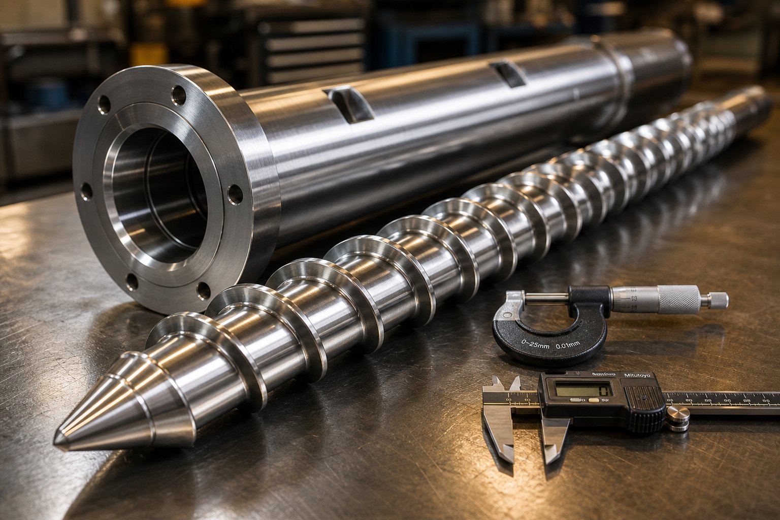
Selecting and Maintaining the Right Extrusion Equipment
Production discipline and quality monitoring only deliver results when the underlying extrusion equipment is properly specified, well maintained, and supported by reliable component suppliers. Whether you are commissioning a new line, scaling capacity, or extending the service life of aging plastic extrusion machines, the decisions you make about hardware directly shape your cost-per-kilogram, uptime percentage, and product consistency for years to come.
Key Factors When Evaluating Extrusion Equipment
Purchasing extrusion machinery is a significant capital commitment, and the wrong specification can lock a plant into performance compromises that no amount of process tuning can overcome. Before evaluating quotes from plastic extruder manufacturers, work through these critical selection criteria:
- Screw diameter and L/D ratio — these two numbers define the extruder's throughput envelope and melting capacity. As extrusion engineering research makes clear, a larger screw diameter achieves target output at lower screw speeds, which reduces shear stress on heat-sensitive polymers. Longer L/D ratios (30:1 to 36:1) improve mixing and homogenization but increase residence time — a concern for thermally sensitive resins.
- Drive power and torque — the motor must deliver sufficient torque across the operational speed range. Under-powered drives limit throughput; over-powered drives add unnecessary capital cost. A practical rule of thumb is that drive power should be at least 2.5 times the theoretical thermal energy required to bring the polymer to processing temperature at the target throughput.
- Barrel metallurgy — abrasive fillers like glass fiber, calcium carbonate, and silica demand bimetallic barrel liners with hardness values exceeding HV 900. Corrosive resins such as fluoropolymers or flame-retardant compounds require corrosion-resistant alloys. Matching barrel material to your resin portfolio prevents premature wear and unplanned downtime.
- Peripheral speed limits — every polymer has a maximum tolerable screw peripheral speed before shear damage occurs. PVC, for instance, tolerates roughly 0.2 m/s, while polyolefins can handle 0.5 m/s or higher. The combination of screw diameter and operating RPM determines peripheral speed, so selecting the right extruder size means balancing throughput targets against material processing limits.
- Control system sophistication — modern plastic extrusion equipment increasingly relies on closed-loop control that links barrel temperatures, screw speed, melt pressure, and downstream puller speed into a single coordinated system. Advanced controls reduce startup scrap, improve dimensional consistency, and enable less experienced operators to maintain tight process windows.
- Downstream equipment compatibility — the extruder is only one element in the line. Cooling tanks, calibration tooling, haul-off units, cutters, and coilers must all be sized and synchronized to match. A plastic pipe extrusion machine rated for 500 kg/hr is only useful if the vacuum tank, spray cooling, and puller can handle that throughput without becoming bottlenecks. Similarly, plastic profile extruders demand calibration tables with sufficient length and cooling capacity for the specific cross-section and line speed planned.
No single extruder serves every application equally well. Each specification is a compromise — between throughput and residence time, between mixing intensity and thermal gentleness, between capital cost and long-term operating efficiency. Extrusion dimensioning studies consistently reinforce that optimizing these trade-offs for your specific product and resin portfolio yields measurably better output quality and lower total cost of ownership than defaulting to a general-purpose configuration.
The Critical Role of Screw Barrel Maintenance and Replacement
Imagine slowly turning up the thermostat in your house by a fraction of a degree each day — you would barely notice the change until the energy bill arrived. Screw and barrel wear works the same way inside an extruder. Wear progresses gradually, and operators compensate instinctively — nudging screw speed up to maintain output, adjusting temperatures to manage discharge consistency — until the cumulative effect becomes impossible to mask.
The symptoms of excessive wear are well documented:
- Reduced specific rate — output per screw RPM drops as the flight clearance widens and polymer leaks backward over the flights instead of being pushed forward.
- Higher discharge temperatures — the increased clearance reduces the heat-transfer coefficient at the barrel wall, and the higher screw speeds needed to compensate add more shear energy to the melt.
- Inconsistent melt quality — wider clearance means less uniform shearing, which produces temperature gradients and viscosity variation in the melt stream. These inconsistencies show up as dimensional drift, surface defects, and reduced mechanical properties in the finished product.
- Increased energy consumption — an extruder working harder to maintain output through a worn screw-barrel assembly consumes more drive energy per kilogram of product.
Three primary wear mechanisms drive this degradation. Abrasive wear is the most common, caused by hard fillers like glass fiber, silica, or mineral particles grinding against screw flights and barrel bore. Adhesive wear occurs when metal-to-metal contact between the screw flight tip and barrel wall — especially during startup or at low throughput — transfers material from one surface to the other. Corrosive wear results from chemically aggressive decomposition products — hydrogen chloride from PVC processing being a prime example — attacking metal surfaces at elevated temperatures.
According to data published in Plastics Technology, a 100 mm diameter extruder running 1 MI polyethylene at 150 kg/hr can see discharge temperatures climb by 10 degrees Celsius and require a rate reduction of up to 13% as flight clearance increases from the original 0.005 inches per side to just 0.016 inches. On a line that runs around the clock, that 13% capacity loss translates directly into missed orders and reduced profitability.
Monitoring wear does not require sophisticated instrumentation — just discipline. Track specific rate (output divided by screw speed) over time; a declining trend signals progressive clearance increase. When the screw is pulled for inspection, measure flight OD at multiple points and compare against original specifications. A standard guideline suggests replacement when flight clearance reaches four times its original value, though critical applications like medical tubing may warrant replacement at two times the original clearance.
Replacement screw barrels should match or exceed OEM specifications for metallurgy, dimensional accuracy, and surface finish. Barrel bores lined with bimetallic alloys typically achieve surface hardness above HRC 60, and machining tolerances of +/- 0.02 mm ensure proper clearance with new or refurbished screws. Bimetallic liners generally last through the service life of three screws, but once the liner is worn through, the barrel itself must be replaced. Keeping a spare screw on hand eliminates the extended downtime that comes with waiting for a replacement to be manufactured and delivered.
Building a Reliable Equipment Support Network
Sourcing a replacement screw barrel is straightforward when you are running a standard polyolefin pipe line with common dimensions. It becomes considerably more complex when you need custom flight geometry for a specialty compound, non-standard L/D ratios for a high-output recycling line, or wear-resistant metallurgy tailored to an abrasive WPC formulation. In those situations, having a relationship with a component supplier who understands the specific demands of your extrusion application — not just the mechanical dimensions of the part — makes the difference between a drop-in solution and a costly trial-and-error cycle.
Look for suppliers who can demonstrate expertise across the full range of plastic extrusion machinery applications: pipe, profile, film, sheet, WPC, and granulation. The ability to recommend screw geometry, barrel alloy, and flight treatment based on your resin, your throughput target, and your downstream equipment setup is far more valuable than simply quoting a part number from a catalog.
NANHAIYA exemplifies this application-focused approach to extrusion component supply. Their screw barrel support covers single-screw and twin-screw platforms across pipe, profile, film, sheet, WPC, and granulation equipment — providing replacement screw barrels and custom configurations engineered for specific processing requirements. For teams evaluating component upgrades, sourcing replacements for aging plastic extrusion machinery, or specifying screw-barrel assemblies for a new line, their product support page offers a practical starting point for exploring configurations matched to real production needs.
The broader lesson is simple: extrusion equipment is a system, not a collection of individual parts. The extruder, the screw barrel, the die, the cooling line, the puller, and the control system all interact. Investing in the right specification upfront, maintaining critical wear components proactively, and partnering with suppliers who understand that interdependence keeps your line running at the performance level your customers — and your margins — depend on.
Frequently Asked Questions About Plastic Extrusion
1. What is plastic extrusion and how does it differ from injection molding?
Plastic extrusion is a continuous manufacturing process where thermoplastic pellets are melted inside a heated barrel and pushed through a shaped die to form products with a uniform cross-section, such as pipes, films, and profiles. Unlike injection molding, which fills a closed mold to produce discrete 3D parts, extrusion generates uninterrupted lengths of product that are cut or coiled downstream. Extrusion tooling costs are typically 80% to 90% lower than injection molds, making it the more economical choice for constant-cross-section products needed in long or continuous lengths.
2. What materials can be used in plastic extrusion?
The most widely extruded thermoplastics include PVC (rigid and flexible), polyethylene variants (HDPE, LDPE, LLDPE), polypropylene, ABS, polycarbonate, and polystyrene. Each resin has a distinct processing temperature window, chemical resistance profile, and mechanical strength suited to specific end uses. Beyond virgin resins, extrusion lines increasingly process post-consumer recycled (PCR) and post-industrial recycled (PIR) feedstocks, as well as emerging bio-based polymers like PLA and PHA. Additives such as UV stabilizers, flame retardants, mineral fillers, and colorants are commonly compounded into the base resin to tailor performance for the target application.
3. What is the difference between single-screw and twin-screw extruders?
Single-screw extruders use one helical screw to convey, melt, and pressurize polymer. They are simpler, less expensive, and ideal for processing pre-compounded resins into pipes, profiles, films, and sheets. Twin-screw extruders feature two intermeshing screws — either co-rotating for high-shear compounding or counter-rotating for gentle, positive-displacement transport. Twin-screw machines excel at intensive mixing tasks such as compounding, masterbatch production, devolatilization, and processing highly filled or recycled materials. The choice depends on whether your application prioritizes dedicated continuous output (single-screw) or material blending versatility (twin-screw). Specialists like NANHAIYA offer custom screw barrel configurations for both platforms at nhyscrew.com.
4. What are the most common defects in plastic extrusion and how do you fix them?
Common extrusion defects include melt fracture (shark-skin texture), die lines, voids, warpage, uneven wall thickness, and surface discoloration. Melt fracture typically results from excessive shear stress at the die exit and is corrected by reducing screw speed or adding processing aids. Die lines stem from damaged or contaminated die surfaces and require cleaning or re-polishing. Voids usually indicate moisture in hygroscopic resins, calling for thorough pre-drying. Warpage points to uneven cooling, which is resolved by rebalancing spray zones or calibration-sleeve contact. Systematic troubleshooting starts with checking melt temperature, shear rate, resin moisture, and die condition before investigating less obvious causes.
5. How do you know when an extruder screw and barrel need replacement?
Key indicators of excessive screw-barrel wear include declining specific rate (output per RPM), rising discharge temperatures, inconsistent melt quality, increased energy consumption, and growing dimensional variability in the finished product. These symptoms develop gradually as flight clearance widens from abrasive, adhesive, or corrosive wear. Track specific rate over time and periodically measure screw flight OD against original specifications. A general guideline recommends replacement when flight clearance reaches four times its original value, though precision applications may warrant earlier action. Replacement barrels and screws should match or exceed OEM metallurgy, dimensional accuracy, and surface finish specifications to restore full performance.
Written by
Nanhaiya Technical Team
Zhoushan Nanhaiya Plastic Machinery Co., Ltd.
The Nanhaiya technical team supports screw and barrel manufacturing projects through application review, technical communication, custom manufacturing coordination, and production and quality control.
Discuss Your Application
Related Articles
More insights on screw barrel technology and plastics processing.

What Nobody Tells You About Screw Barrel For Plastic Machine Design
Oct 10, 2026
Learn how screw barrel for plastic machine design affects melt quality, throughput, and wear life. Covers geometry, resin matching, troubleshooting, and sourcing.
Read Article
Single Screw Extruder for Sheet: Stop Guessing, Start Specifying
Oct 9, 2026
Learn how to specify a single screw extruder for sheet production. Covers screw geometry, resin-specific processing, troubleshooting, and maintenance best practices.
Read Article
PE Pipe Extruder Machine: What Datasheets Won't Tell You
Oct 9, 2026
Learn how a PE pipe extruder machine works, key specs explained, material grade selection, maintenance tips, and buyer guidance beyond the datasheet.
Read ArticleLooking for something else?
Search by material, symptom or product and jump straight to the relevant page.
These are navigation suggestions based on keyword matching — not a quotation, not a delivery commitment, and not a substitute for engineering review. Final specification is confirmed by our engineers against your drawings and processed material.
Need help with screw barrel selection?
Share your machine model, processed material and application. Our team can help with pricing and technical support.