

What a Plastic Extruder Screw Manufacturer Actually Does
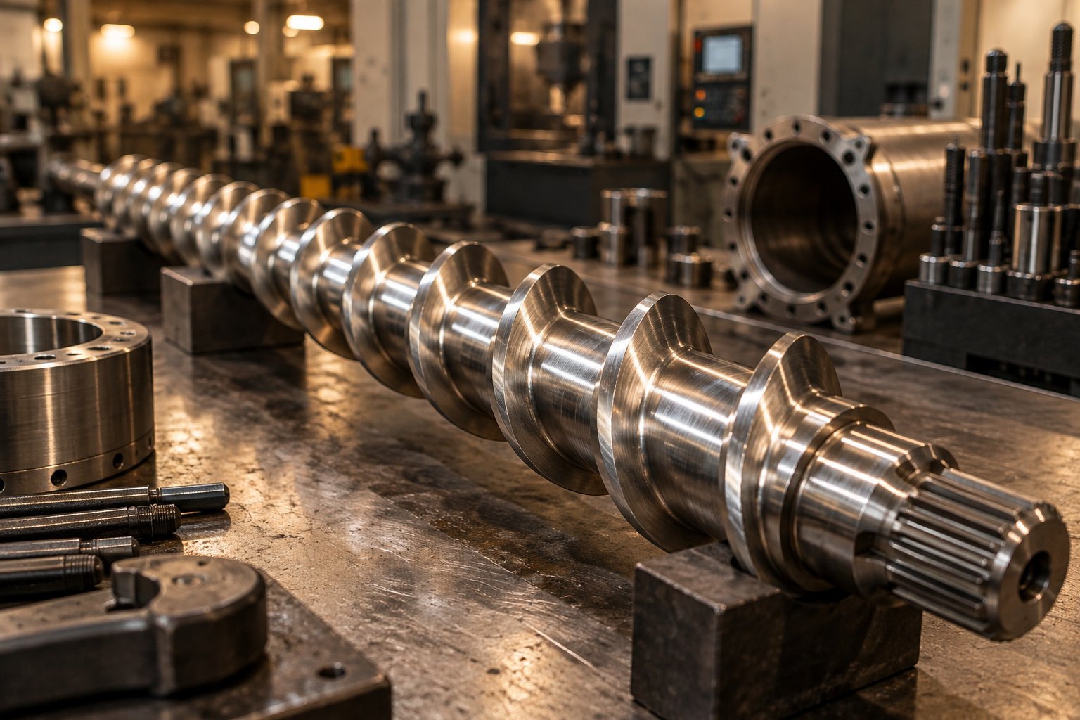
A plastic extruder screw manufacturer is a specialized engineering firm that designs, precision-machines, and supplies screws and barrels for plastic processing equipment used in both extrusion and injection molding. These companies do far more than cut metal. They combine polymer science, mechanical engineering, and metallurgy to produce the single component that most directly controls how raw resin becomes a finished product.
Yet most buyers treat screw purchasing as a simple replacement parts transaction. That gap between what manufacturers know and what buyers understand is exactly where costly mistakes happen.
Defining the Plastic Extruder Screw Manufacturer
Imagine ordering a high-performance engine without understanding horsepower, torque, or fuel compatibility. That is essentially what happens when processors buy an extruder screw without grasping the engineering behind it. A reputable manufacturer does not just ship hardware. They analyze your resin type, throughput targets, and processing challenges, then engineer a screw geometry and select a metallurgy tailored to those conditions. Their scope typically includes custom screw design, CNC machining of flight profiles, heat treatment and surface hardening, barrel bore honing, and quality inspection against tight dimensional tolerances.
In the broader plastics supply chain, these firms sit between equipment OEMs and the processors who run production lines daily. Whether you operate a single-screw line producing PE pipe or a twin-screw compounder blending recycled nylon, the screw is the component that determines whether your operation runs profitably or burns through energy, material, and downtime.
Why Screw Selection Drives Processing Success
The extruder screw is often called the "heart" of the extruder, and for good reason. It performs three critical functions simultaneously: conveying, melting, and mixing the polymer as it travels from the hopper to the die. Every pellet that enters your machine depends on the screw to deliver uniform melt temperature, consistent pressure, and thorough homogenization. Get the screw wrong, and you'll notice surging output, poor surface finish, excessive melt temperatures, or degraded resin, no matter how well you tune your barrel heaters or downstream equipment.
The extruder screw is the single most influential component determining melt quality, throughput, and energy efficiency in any plastic processing operation.
This is why choosing the right screw, and the right manufacturer to build it, has an outsized impact on your bottom line. A well-engineered plastic extruder screw reduces energy consumption per pound of output, extends run times between maintenance intervals, and opens the door to processing higher-value resins or recycled feedstocks that demand tighter process control.
What This Guide Covers
This article is not a sales pitch for any single supplier. It is a manufacturer-agnostic engineering guide designed to put real decision-making power in your hands. Here is what you will walk away with:
- Screw anatomy - a detailed breakdown of every zone from shank to tip, so you can speak your manufacturer's language.
- Design principles - how L/D ratio, compression ratio, and flight geometry shape processing performance.
- Single-screw vs. twin-screw selection - when each configuration makes sense and how it affects sourcing.
- Metallurgy and coatings - the material science behind wear resistance and service life.
- Resin-to-screw compatibility - matching screw designs to specific polymer families.
- Wear diagnosis - how to spot problems early and decide between refurbishment and replacement.
- Quality benchmarks - the inspections and certifications every credible manufacturer should provide.
- Manufacturer evaluation criteria - a practical framework for comparing suppliers and engaging them effectively.
The deeper you understand what goes into a screw plastic extruder systems rely on, the harder it becomes for any supplier to cut corners at your expense. That understanding starts with knowing exactly what is inside the barrel, which is where the anatomy of the extruder screw itself comes into focus.
Anatomy of an Extruder Screw From Shank to Tip
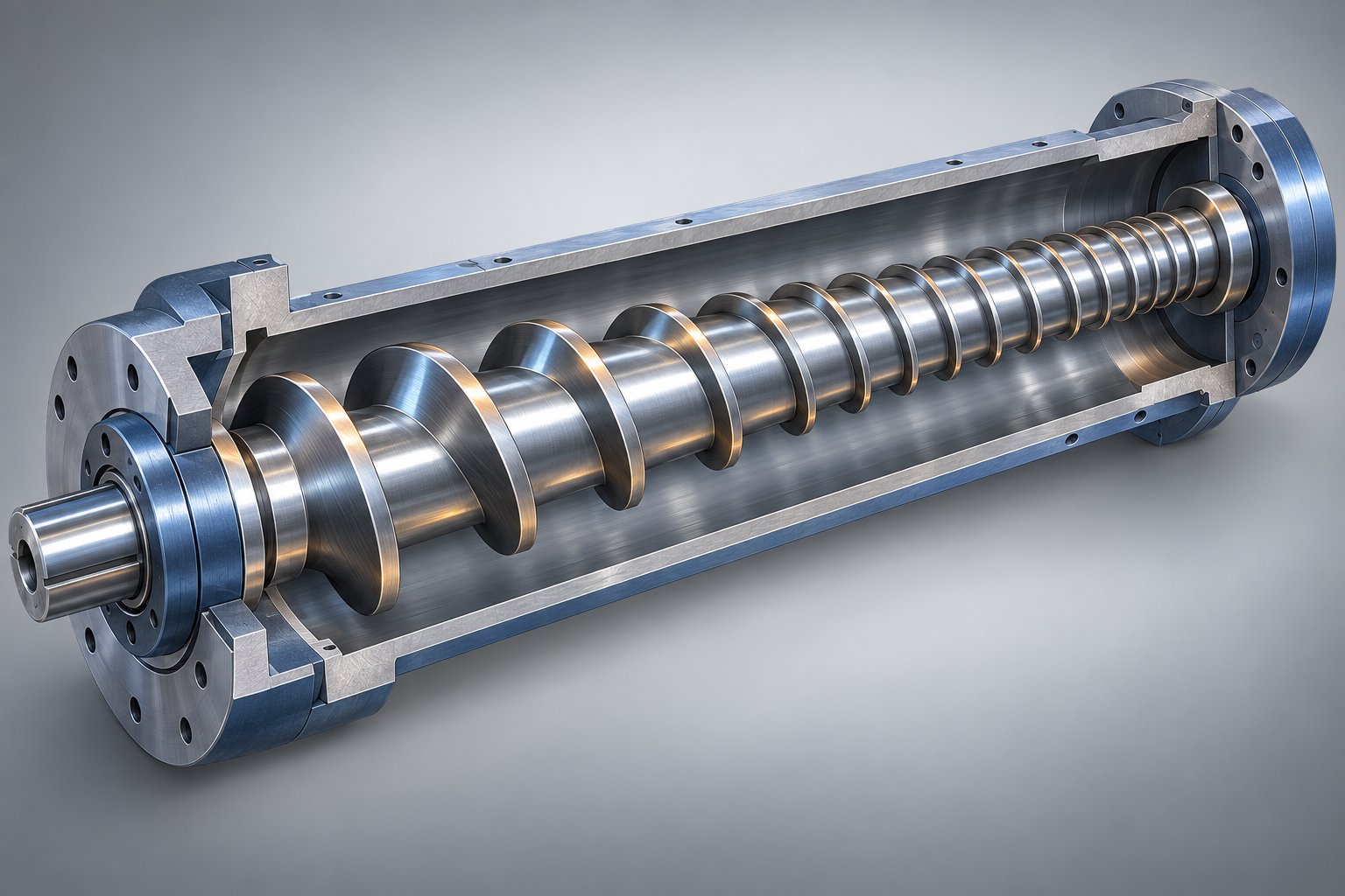
Pick up any extruder screw and you are holding a single piece of steel that performs half a dozen engineering functions across its length. Each zone along that shaft has a distinct geometry, a specific job, and design trade-offs your manufacturer weighs every time they cut a new profile. Understanding these zones — and how they interact — transforms you from someone ordering a part number into someone who can challenge a quote, diagnose a processing issue, or request an optimization with confidence.
Let's walk through every component, starting at the drive end and finishing at the discharge tip.
Shank and Drive Connection
The shank is the rearmost section of the screw — the stub that slides into the gearbox output shaft and transmits rotational torque from the motor. You will typically see a splined or keyed profile machined into the shank to prevent slippage under load. This connection point may seem simple, but it absorbs the full torsional force the drive system delivers. A poorly machined shank or a worn keyway introduces play that accelerates wear on both the gearbox and the screw itself.
Directly forward of the shank sits the thrust bearing interface, which resists the axial forces generated by die-head pressure pushing back against the screw. The load here equals the screw's cross-sectional area multiplied by that back pressure — a force that can reach thousands of pounds in large-diameter extruder screws. If the thrust bearing assembly is undersized or misaligned, the screw can shift axially, creating uneven flight clearances and erratic output.
Feed, Transition, and Metering Zones Explained
Beyond the shank, the working length of the screw divides into three primary zones. Think of them as chapters in a story: each one picks up where the previous one left off, progressively converting solid pellets into a pressurized, homogeneous melt.
Feed zone. This is where solid pellets drop from the hopper, pass through the feed throat, and enter the extruder feed barrel. The channel between flights is at its deepest here — maximum volume to accept low-bulk-density solids and begin conveying them forward. Friction between the pellets and the barrel wall is what drives material ahead; the screw surface ideally stays polished so pellets grip the barrel rather than spinning in place. Water-cooled jackets around the feed throat prevent premature melting that would cause pellets to stick and restrict flow.
Transition (compression) zone. As material advances, the channel depth gradually decreases. This shrinking channel compresses the solid bed, squeezing out trapped air and forcing polymer against the heated barrel extruder wall. The combination of compressive friction and conducted heat initiates melting. Channel depth reduction is typically linear, though some high-performance designs use a progressive taper to manage the melt rate more precisely. Too aggressive a compression and you'll generate excessive shear heat; too gentle and you'll push unmelted solids into the next zone.
Metering zone. Here the channel depth levels off at its shallowest. The job shifts from melting to homogenizing: ensuring uniform melt temperature, eliminating any remaining solid particles, and building the consistent pressure needed to push material through the screen pack and die. Output rate and melt quality are largely determined by the metering zone's depth, length, and flight geometry.
The table below summarizes how each zone contributes to the overall process:
| Zone | Function | Typical Channel Depth Characteristic | Key Design Consideration |
|---|---|---|---|
| Feed | Accepts solid pellets from the hopper and conveys them forward via frictional drag | Deep — maximum volume for solids intake | Depth must match resin bulk density; too shallow starves the screw, too deep causes feed instability |
| Transition / Compression | Compresses the solid bed, initiates melting through friction and barrel heat transfer | Progressively decreasing from feed depth to metering depth | Compression rate controls melt uniformity; too rapid risks shear overheating, too slow allows unmelted solids to pass |
| Metering | Homogenizes melt temperature, removes remaining solids, builds consistent die-head pressure | Constant and shallow | Depth sets shear rate and throughput; must balance output volume against melt temperature rise |
| Mixing (optional) | Enhances distributive or dispersive mixing of colors, additives, or temperature variations | Varies by mixer type — pins, slotted flights, or undercut channels | Mixer selection depends on whether the goal is shear intensity (dispersive) or melt redistribution (distributive) |
Mixing Elements and Tip Assemblies
Not every screw ends with a plain metering section. Many extruder screws include dedicated mixing elements between the metering zone and the tip — and the type of mixer your manufacturer selects can dramatically affect melt quality.
Dispersive mixers force melt through narrow gaps to apply intense shear. The Maddock (also called Leroy or UCC) mixer is the most common example — a series of alternating inlet and outlet channels separated by a barrier that the melt must cross. Newer spiral Maddock designs combine features of the original Maddock and Egan layouts, and they are widely used for crystalline polymers like polyolefins where completing the melt is critical. However, on barrier screws where melting is already handled upstream, a dispersive mixer can unnecessarily elevate melt temperature and reduce output.
Distributive mixers take a gentler approach. Instead of shearing the melt through tight clearances, they repeatedly divide and recombine the flow stream to blend colors, additives, or thermal gradients. Common types include Saxton mixers (multiple helical channels with interrupted flights), pin mixers (rows of pins that split the melt exponentially), and pineapple mixers (converging channels for chaotic mixing). As extrusion authority Jim Frankland has noted, distributive mixers are usually the better fit for barrier screws because the melting work is already done — adding dispersive shear on top only wastes energy and raises melt temperature.
At the very end of the screw sits the tip assembly, and its design depends on the application. In extrusion, the screw tip simply pushes melt against a breaker plate — a perforated metal disc that breaks up the spiral flow pattern and supports filter screens to catch contaminants. In injection molding, the tip incorporates a non-return valve (check ring) that allows melt to flow forward during screw recovery but seals shut during injection to prevent backflow. A worn or improperly seated check ring is one of the most common sources of shot-to-shot inconsistency in injection molding.
Flight geometry ties all these zones together. Three dimensions matter most across the entire screw length:
- Flight width — the axial thickness of each flight land. Wider flights provide structural strength but reduce the open channel area available for material flow.
- Helix angle — the angle the flight makes relative to a plane perpendicular to the screw axis. A standard square-pitch screw (pitch equals diameter) produces a helix angle of roughly 17.65 degrees. Steeper angles boost forward conveying; shallower angles favor pressure generation.
- Flight clearance — the radial gap between the flight tip and the barrel ID, generally 0.001 times the screw diameter, ranging from 0.0005 to 0.0020. Too tight and the screw may contact the barrel wall; too loose and melt leaks backward over the flights, reducing pumping efficiency and increasing energy consumption.
Every zone, every mixer, every dimensional tolerance along this shaft represents a design decision your manufacturer made — or should have made — based on the resin you process and the results you need. The real question is how those decisions are made: what design parameters drive them, and how do choices like L/D ratio and compression ratio translate into processing performance?
Screw Design Fundamentals That Shape Processing Performance
Two screws can look nearly identical lying side by side on a workbench — same diameter, same overall length, same polished finish — yet produce wildly different results in your extruder. The difference lives in a handful of design parameters that your plastic extruder screw manufacturer adjusts, sometimes by fractions of an inch, to balance output rate against melt quality, mixing intensity against thermal sensitivity, and pumping efficiency against residence time. Understanding these parameters is what separates a buyer who simply accepts a quote from one who can push back on design choices with real engineering reasoning.
Understanding L/D Ratio and Compression Ratio
L/D ratio — the length-to-diameter ratio — is the first number any screw extruder specification sheet mentions, and for good reason. It defines how much working length the polymer has to travel from feed throat to discharge. A longer screw gives the resin more time to melt, mix, and homogenize. A shorter one reduces residence time but limits how much thermal and mechanical energy you can input. The most common L/D for single-screw extrusion sits around 24:1, with high-performance applications pushing to 30:1 or even 36:1 when superior mixing or venting is required. Injection molding screws, by contrast, typically run between 18:1 and 24:1 because the screw also needs to function as an injection ram — a dual role that limits practical length.
Here is a quick way to visualize it: on a square-pitch extrusion screw (where the distance between flights equals the screw diameter), L/D roughly equals the number of turns. Count the flights and you essentially know the L/D — though technically the portion sitting under the feed opening should not be included.
Compression ratio is the second critical parameter. It represents the ratio of the feed zone channel volume to the metering zone channel volume. On a constant-pitch screw, this simplifies to the ratio of feed depth to metering depth. Most designs fall between 2:1 and 4:1, though the ideal number depends entirely on the resin being processed. A high compression ratio (3.5:1 or above) works well for crystalline polyolefins that can tolerate aggressive shear and need significant densification. A low compression ratio (2:1 to 2.5:1) is essential for shear-sensitive materials like PVC or certain TPEs, where excessive compression generates destructive heat.
Sounds abstract? Think of it this way: compression ratio controls how aggressively the screw squeezes the solid bed. Too much compression and you overheat the melt. Too little and unmelted pellets survive into the metering zone, causing gels and surface defects in your final product.
Two additional parameters quietly shape what happens inside the barrel. Flight pitch — the axial distance from one flight to the next — governs how quickly material advances per revolution. A square pitch (pitch equals diameter) is the industry standard, but variable-pitch designs can accelerate or decelerate material flow in specific zones to fine-tune pressure profiles. Channel depth profiles define the rate at which the root diameter changes through the transition zone. A linear taper is common, but progressive or multi-rate tapers allow manufacturers to manage melt rate more precisely, especially for resins that soften over a narrow temperature window.
General Purpose vs Barrier vs Mixing Screw Designs
Every screw design represents a philosophy about how to manage the melting and mixing process. Here are the most common types you will encounter when evaluating screw extruders and their respective design approaches:
- General-purpose (GP) screw — A single-flighted, three-zone design (feed, transition, metering) suitable for a broad range of resins but optimized for none; the default choice when processing well-characterized, pre-compounded materials at moderate output rates.
- Barrier screw (Maillefer type) — Incorporates a secondary barrier flight in the transition section that creates separate channels for solids and melt, preventing solid-bed breakup and dramatically improving melting efficiency and melt uniformity.
- Barrier screw (Barr type) — A variation on the barrier concept that uses a different channel geometry and barrier clearance strategy to manage the solid-melt separation, often paired with specific downstream mixing sections for further homogenization.
- High-performance mixing screw — Combines a barrier melting section with an intensive distributive or dispersive mixing element (such as a Maddock, Saxton, or pin mixer) in the metering zone to deliver both complete melting and thorough additive or color dispersion.
- Wave screw — Features two or three parallel channels with oscillating depths that are out of phase, forcing melt to flow back and forth across a low barrier flight for excellent mixing and flow stabilization without extreme shear.
- Vented (two-stage) screw — An extended-length design where the first stage melts the polymer completely, then channel depth suddenly increases to reduce pressure at a barrel vent port for moisture or volatile removal before the second stage re-pressurizes and meters the melt.
The distinction between GP and barrier designs is worth emphasizing. In a conventional single-flighted screw, the solid bed eventually becomes too thin to hold together under the channel's internal pressure. It fractures — a phenomenon called solid-bed breakup — and unmelted pellet fragments disperse into the melt pool. This is a major source of melt inconsistency in both extrusion and injection molding. Barrier screws solve this by physically separating solids from melt with an undercut flight. The barrier clearance is large enough for molten polymer to flow over into a dedicated melt channel but small enough to block solid pellets. The result: significantly higher melting capacity per unit of screw length, elimination of solid-bed breakup, and better melt uniformity at higher throughput rates.
How Injection Molding Screws Differ From Extrusion Screws
If you process on both platforms, you already know the machines look different. The screws inside them differ in equally fundamental ways — and a manufacturer that treats an injection screw as a shortened extrusion screw is cutting corners on your behalf.
An extrusion screw rotates continuously, conveying a steady stream of melt to the die at constant pressure. Its design optimizes for uninterrupted output over hours or days. An injection molding screw, however, lives a cyclical life. During the plasticating phase, it rotates to melt resin and build a shot in front of the screw tip — then it stops rotating and rams forward hydraulically to inject that shot into the mold cavity. This reciprocating action means the screw must function as both a plasticator and a piston.
Several design consequences follow from this dual role:
- Shorter L/D ratio — typically 18:1 to 24:1, because the screw must fit within a barrel that also accommodates the stroke length for shot delivery.
- Non-return valve (check ring) — mounted at the screw tip, this valve allows melt to flow forward during recovery but seals shut during injection to prevent backflow. No extrusion screw requires one.
- Emphasis on shot-to-shot consistency — while an extrusion screw is tuned for continuous throughput, an injection screw must deliver the exact same melt volume and temperature every cycle, often at cycle times measured in seconds.
- Different shear and pressure profiles — an injection screw typically operates against lower and more variable back pressures during plasticating, but must withstand very high injection pressures (often exceeding 20,000 psi) during the forward stroke.
This means the same resin — say, a 30% glass-filled nylon — may call for a completely different screw geometry and metallurgy depending on whether it runs in an extruder or an injection molding machine. A manufacturer with depth in both platforms will understand those differences intuitively. One focused exclusively on extrusion may underestimate the cyclic stress and check-ring tolerances that injection applications demand.
Design parameters and screw types define the mechanical blueprint. But a blueprint means little if the steel behind it cannot survive the processing environment — and that is where metallurgy, the most commonly overlooked factor in screw specification, enters the conversation.
Single Screw vs Twin Screw and Choosing the Right Configuration
Metallurgy and coatings matter enormously — but they only become relevant after you answer a more fundamental question: does your application call for one screw inside the barrel, or two? This decision reshapes everything downstream, from flight geometry and mixing intensity to which screw manufacturer you should even be talking to. Many buyers skip this step entirely, defaulting to whatever configuration their current machine uses. That default can cost you throughput, quality, or both.
When Single Screw Extruders Are the Right Choice
Single-screw extruders dominate applications where the process is well characterized and the resin arrives pre-compounded. Think PE pipe, blown film, flat sheet, or PVC profiles — operations where the screw's primary job is to melt, homogenize, and pressurize a known material at steady-state conditions. The advantages are straightforward: lower capital cost, simpler mechanical design, fewer wear parts, and easier maintenance. For processors running millions of pounds of a single polyolefin grade per year, a properly engineered single-screw line delivers excellent cost-per-pound economics.
Single screw extruder manufacturers also benefit from decades of refined design data for commodity processes. General-purpose, barrier, and wave screw geometries have been optimized extensively for these applications, meaning lead times for replacement screws are often shorter and pricing is more competitive.
The limitation? Mixing. A single screw relies on drag flow and channel geometry to blend the melt, which works fine for pre-compounded resins but falls short when you need to incorporate raw additives, disperse pigments at tight color tolerances, or process highly filled compounds.
Twin Screw Configurations and Their Applications
Twin screw extruders solve the mixing problem by introducing intermeshing flight geometry that creates complex flow fields no single-screw design can replicate. Two screws working together deliver superior distributive and dispersive mixing, self-wiping action that minimizes dead zones, and the ability to configure modular screw elements along the barrel length for precise control over shear, temperature, and residence time.
The configuration splits into two distinct families:
- Co-rotating twin screws — Both screws turn in the same direction with fully intermeshing, self-wiping geometry. High shear stress develops between the screws and between the screws and barrel, producing intense mixing with narrow residence-time distribution. This makes co-rotating designs ideal for compounding with inorganic fillers, producing polymer alloys, reactive extrusion, devolatilization, and processing engineering plastics. They are the workhorse of masterbatch production and recycled-resin compounding lines worldwide.
- Counter-rotating twin screws — The screws rotate in opposite directions, generating a calendering effect at the intermeshing region that disperses material under gentler conditions. Shear heating stays low, which is critical for thermally sensitive polymers. Rigid PVC pipe, sheet, and profile extrusion rely heavily on counter-rotating designs because PVC's narrow processing window demands low-shear, low-temperature forming that co-rotating machines struggle to deliver.
Beyond these core architectures, twin screw extruders offer venting capability that single-screw machines cannot match without specialized two-stage designs. Multiple barrel vent ports allow moisture removal, devolatilization of solvents, and extraction of reaction byproducts — capabilities essential for processing hygroscopic polymers, recycled flake, and reactive formulations.
The twin screw extruders market reflects this expanding role. Twin-screw machines held 46.37% of global plastic compounding machinery market share in 2025, driven largely by demand for compounding recycled resins, engineering polymers, and specialty materials that require the mixing intensity and process flexibility only twin screws provide. Recycled-content mandates in Europe and North America are accelerating this trend, as post-consumer flake demands robust mixing, filtration, and devolatilization that push processors toward twin-screw platforms.
The table below highlights how the two architectures compare across the dimensions that most influence a buyer's decision:
| Dimension | Single-Screw Extruder | Twin-Screw Extruder |
|---|---|---|
| Typical Applications | Film, pipe, profile, sheet extrusion with pre-compounded resins | Compounding, reactive extrusion, devolatilization, recycled-resin processing, masterbatch production |
| Mixing Capability | Moderate — relies on screw geometry and optional mixing elements | Excellent — intermeshing screws create complex shear and elongational flow fields |
| Capital Cost | Lower — simpler drive train, single barrel bore | Higher — dual drive systems, precision-bored barrel, modular screw elements |
| Maintenance Complexity | Low — fewer wear components, straightforward screw removal | Moderate to high — modular elements require careful assembly; two screws and a more complex barrel to inspect |
| Screw/Barrel Replaceability | Widely available; standard diameters and geometries from many suppliers | More specialized; modular screw elements must match OEM specifications precisely |
How Screw Type Impacts Manufacturer Selection
Here is the part most buyers overlook: your choice between single and twin screw directly determines which manufacturers belong on your shortlist. Twin screw extruder manufacturers tend to specialize in modular element design, segmented barrel construction, and the metallurgical expertise needed for the high-torque, high-wear environment twin screws operate in. A company that excels at building one-piece single screws for film lines may lack the element libraries, assembly tolerances, or process knowledge required to supply quality twin-screw replacement parts.
Conversely, a twin-screw extruder manufacturer focused on co-rotating compounding lines may have limited experience with the barrier flight geometries, wave screw profiles, and check-ring assemblies that single-screw and injection molding applications demand. The best approach is to verify that any supplier you evaluate has documented experience with your specific configuration — not just the general machine category.
If you are weighing a switch from single to twin screw (or vice versa), a knowledgeable manufacturer can walk you through the processing trade-offs and total cost of ownership rather than simply quoting the hardware. That conversation should always include one topic most suppliers gloss over: the metallurgy and surface treatments that determine how long your screws and barrels actually last in service.
The Metallurgy Behind High-Performance Extruder Screws and Barrels
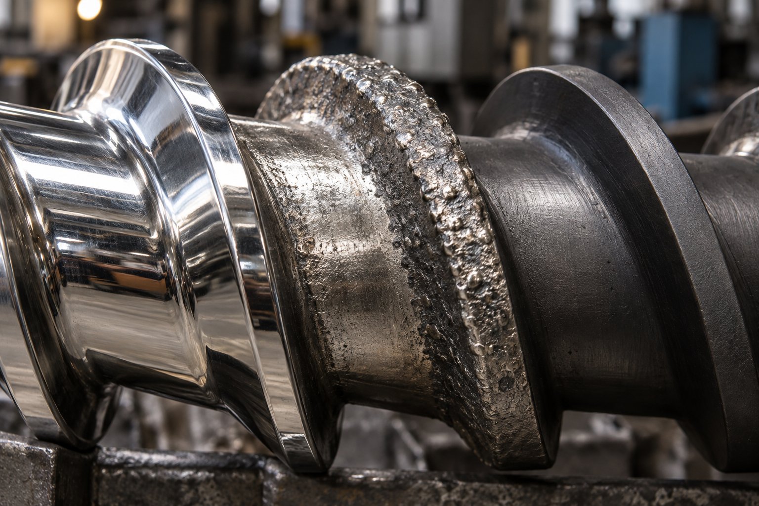
Most conversations about extruder screws and barrels focus on geometry — flight depth, compression ratio, mixing elements. Metallurgy rarely gets the same attention, and that is a costly oversight. You can engineer the perfect screw profile for your application, but if the steel underneath cannot survive the chemical and mechanical environment inside your extruder barrel, that geometry erodes away in a fraction of its expected service life. The material science behind the screw is every bit as important as the shape of the screw.
Here is what makes this topic especially tricky for buyers: the wrong metallurgy choice does not cause an immediate, dramatic failure. It causes accelerated wear — a slow, silent drain on output, melt quality, and energy efficiency that compounds over months until you are forced into an unplanned shutdown and an emergency replacement order. A knowledgeable manufacturer matches the steel and surface treatment to the resin you process, the fillers you use, and the corrosive byproducts your compound generates. A less diligent one ships the default option and lets you absorb the consequences.
Standard Nitrided Steel for Commodity Resins
For the majority of general-purpose applications — unfilled polyolefins, standard ABS, HIPS, and other non-abrasive, non-corrosive commodity resins — nitrided alloy steel is the baseline and often the right choice. The most common base steels are 4140 and 4340 (or their international equivalents like 38CrMoAlA), medium-carbon alloys that offer good mechanical strength at a reasonable price point.
Nitriding is a heat-treatment process that diffuses nitrogen into the steel surface, creating a hardened case that improves both wear resistance and moderate corrosion resistance. The result is a surface hardness significantly above the core steel, providing a durable running surface for the flight lands and root.
But there is a key limitation most buyers do not realize until it is too late: the nitrided layer is thin — typically only a few thousandths of an inch deep. This means that once a nitrided screw wears past that case depth, you are running on soft core steel, and wear accelerates dramatically. Worse, if you send the screw out for regrinding to restore flight dimensions, the regrinding process removes the hardened layer entirely. You get your dimensions back but lose the surface protection that made the screw last in the first place.
For processors running millions of pounds of clean, unfilled PE or PP per year, nitrided 4140 delivers excellent economics. The upfront cost is the lowest of any option, and service life is perfectly adequate when neither abrasion nor corrosion is a significant factor. The moment you introduce glass fiber, mineral fillers, or corrosive polymers like PVC into the equation, however, nitriding alone is no longer sufficient — and continuing to run it is essentially choosing to replace your extrusion barrel and screw on an accelerated schedule.
Bimetallic and Tool Steel Solutions for Filled Compounds
When your resin contains abrasive fillers, reinforcements, or corrosive additives, the metallurgy conversation shifts to bimetallic construction and premium tool steels — a step up in both performance and investment.
Bimetallic barrels are the industry standard for demanding applications. A bimetallic extruder barrel consists of two distinct layers: a high-strength alloy steel outer shell that provides structural rigidity, and a wear- and corrosion-resistant alloy liner metallurgically bonded to the bore through centrifugal casting. During this process, molten alloy is spun inside the barrel shell at high speed, ensuring dense bonding between layers and uniform alloy thickness. After casting, precision heat treatment and CNC machining bring the bore to final tolerance.
The protective alloy liner is substantially thicker than a nitrided case — this is not a surface treatment that wears through in thousands of an inch. Different alloy formulations can be selected depending on whether the dominant threat is abrasion, corrosion, or both. Nickel-based alloys emphasize corrosion resistance for PVC and flame-retardant compounds. Tungsten-carbide-loaded compositions prioritize abrasion resistance for glass-filled and mineral-filled materials. Balanced formulations address combined threats. Industry data confirms that bimetallic liners can extend extruder barrel life by three to five times compared to standard nitrided barrels under abrasive conditions.
The trade-off is higher upfront cost. But for processors running glass-filled nylon, mineral-loaded compounds, or contaminated recycled feedstock, the extended service life almost always pays back the cost difference many times over. Bimetallic is not the upgrade for these applications — it is the baseline.
Premium tool steels serve a similar purpose on the screw side. Grades like D2 (a high-carbon, high-chromium cold-work steel), H13 (a hot-work tool steel with excellent thermal fatigue resistance), and CPM series powdered metallurgy steels offer significantly higher hardness and wear resistance than standard 4140 or 4340. These are typically specified for screw flights and mixing elements exposed to the most aggressive abrasion — think 30%+ glass-fiber-filled engineering resins where standard nitrided flights would lose measurable diameter in weeks rather than months.
Here is a practical breakdown of the metallurgy hierarchy and where each option fits:
- 4140/4340 nitrided steel — Ideal for unfilled commodity polyolefins (PE, PP), general-purpose HIPS, and ABS where abrasion and corrosion are minimal. Lowest cost, adequate service life for clean resins.
- Bimetallic barrel with nickel-based alloy liner — Best for corrosive polymers such as PVC, flame-retardant compounds, and fluoropolymer processing where acidic off-gases attack standard steel. Provides excellent chemical resistance with moderate wear protection.
- Bimetallic barrel with tungsten-carbide-loaded liner — Designed for highly abrasive applications including glass-filled nylon, mineral-filled polypropylene, and recycled resins containing contaminants. Maximum bore wear resistance.
- D2 tool steel screw flights — Suited for high-abrasion extrusion applications where flight tip wear is the primary failure mode. Through-hardened for consistent hardness across the flight cross-section.
- H13 tool steel — Excels in high-temperature applications where thermal cycling and hot hardness matter, such as engineering plastics processed at elevated barrel temperatures.
- CPM powdered metallurgy steels (e.g., CPM 9V, CPM 10V) — The premium tier for extreme abrasion resistance. Uniform carbide distribution throughout the steel matrix delivers consistent wear performance even after regrinding — a key advantage over conventional tool steels with less uniform microstructure.
Coatings and Surface Treatments That Extend Service Life
Beyond base metal selection, surface treatments and applied coatings add another layer of protection — literally. These treatments can be applied to screws made of standard or tool steels to enhance specific performance characteristics without replacing the entire component with a more expensive alloy.
Chrome plating deposits a thin, hard, corrosion-resistant layer onto the screw surface through electroplating. Its primary strength is chemical resistance combined with low friction, making it the go-to choice for extrusion barrels and screws processing PVC, where hydrochloric acid off-gas aggressively attacks unprotected steel. Double or triple chrome layers build additional thickness for more severe corrosive duty. The limitation? Chrome is a thin layer with limited abrasion resistance. Against glass fiber or heavy mineral filler, chrome wears through relatively quickly, exposing the base steel beneath. Chrome fights corrosion — it is not a wear solution.
Stellite hardfacing is a cobalt-based alloy welded directly onto screw flight crests. It delivers good wear resistance at elevated temperatures and handles metal-to-metal contact well. Stellite grades (such as Stellite 6 and 12) have long been used for general-purpose flight protection where moderate abrasion is present. A practical advantage: hardfaced flights are re-weldable, meaning worn flights can be rebuilt and re-hardfaced multiple times — a significant cost advantage over nitriding, which is gone after a single regrind.
Nickel-based hardfacing (Colmonoy) takes wear protection a step further. Colmonoy 56, a nickel-chrome-boron alloy, protects against mildly corrosive and mildly abrasive resins — a dual-threat capability Stellite cannot match as effectively. For the most demanding abrasion scenarios, Colmonoy 83 incorporates tungsten carbide particles into the nickel matrix, delivering extreme wear resistance suited to glass-filled nylon and heavily loaded engineering compounds.
Tungsten carbide coatings represent the top of the abrasion-resistance hierarchy. Applied through thermal spray processes or embedded in hardfacing alloys, tungsten carbide provides the hardest wear surface commercially available for extruder screws. It is the right answer when your dominant enemy is mechanical grinding from glass fibers, ceramic fillers, or abrasive recycled-material contaminants. But here is the critical nuance most suppliers will not volunteer: tungsten carbide is a wear specialist, not a corrosion specialist. On its own, it does not protect against the acidic pitting that PVC or flame-retardant compounds cause. Choosing carbide for a corrosion problem is the classic "most expensive equals best" mistake — you spend more and still get pitting.
The most expensive coating mistake is not choosing a cheap treatment — it is choosing the wrong type of protection for the actual threat. A treatment that fights corrosion does not necessarily fight wear, and vice versa.
This is precisely why a capable manufacturer asks detailed questions about your resin, filler package, and processing temperatures before recommending a metallurgy. The right answer is never a one-size-fits-all default. It is a diagnosis: is your enemy corrosion, abrasion, or both? Corrosion points to chrome plating or nickel-based alloys. Abrasion points to hardfacing, carbide, or bimetallic construction. Combined threats — filled PVC, contaminated recycled streams — demand a layered strategy, typically a bimetallic extrusion barrel paired with a hardened, corrosion-resistant screw. Matching the metallurgy to the threat is what separates a supplier who understands material science from one who simply ships parts.
Steel and coatings define how long your equipment lasts. But the specific resin flowing through that equipment determines which metallurgy and which screw geometry you actually need — a pairing that varies dramatically from one polymer family to the next.
Matching Screw Designs to Specific Polymer Families
Every polymer behaves differently under heat and shear. A screw barrel combination that runs HDPE flawlessly can destroy PVC in minutes, and a geometry optimized for rigid PVC will starve a nylon line of the mixing energy it needs. Yet many buyers order replacement screws based on machine diameter alone, treating the resin as an afterthought. That approach virtually guarantees a mismatch between what the screw delivers and what the polymer demands.
The table below maps common polymer families to recommended screw designs, compression ratios, and barrel metallurgy considerations. Use it as a starting reference whenever you engage a manufacturer about a new or replacement extrusion screw barrel — then dig into the details that follow.
| Polymer Family | Recommended Screw Type | Compression Ratio | Key Processing Consideration | Barrel Metallurgy Note |
|---|---|---|---|---|
| PE (HDPE/LDPE) | General-purpose or barrier screw | 3.0 - 3.5:1 | High crystallinity requires aggressive compression and longer L/D (around 30:1) for complete melting | Standard nitrided barrel adequate for unfilled grades |
| PP | General-purpose or barrier screw | 3.5 - 4.0:1 | Sharp melting point benefits from a barrier design; moderate shear tolerance | Standard nitrided barrel for unfilled; bimetallic for talc- or glass-filled grades |
| PVC (rigid and flexible) | Low-compression, low-shear design; often counter-rotating twin screw barrel for profiles | 2.0 - 2.5:1 | Thermally sensitive — degrades rapidly with excessive shear, releasing corrosive HCl gas | Corrosion-resistant nickel-alloy bimetallic barrel or chrome-plated bore required |
| Nylon / PA (PA6, PA66) | Barrier screw with venting capability | 3.5 - 4.0:1 | Highly hygroscopic — moisture causes hydrolysis; steep compression is tolerable due to high melt fluidity | Standard nitrided for unfilled; tungsten-carbide bimetallic for glass-filled grades |
| ABS | General-purpose or mixing screw with controlled shear | 2.5:1 | Mildly thermally sensitive; excessive shear causes yellowing and surface defects | Standard nitrided barrel; chrome plating if running flame-retardant grades |
| PC (Polycarbonate) | Barrier or GP screw with distributive mixing; longer L/D (around 30:1) | 2.5:1 | Thermally sensitive and hygroscopic; requires thorough drying and careful temperature control | Standard nitrided for unfilled; bimetallic for glass-filled |
| PET / PETG | Low-compression design similar to PVC approach | 2.5:1 | Thermally sensitive and extremely hygroscopic — absorbs enough moisture to affect processing in as little as 15 minutes | Standard nitrided barrel with corrosion-aware alloy for acidic degradation byproducts |
| TPU / TPE | Low-compression, open-channel design with minimal restrictive mixing | 2.0 - 2.5:1 | Shear-sensitive elastomers — excessive restriction causes overheating and loss of elastic properties | Standard nitrided or chrome-plated screw barrel for slip and release |
Screw Recommendations for Commodity Polyolefins
PE and PP are the highest-volume resins processed worldwide, and they are forgiving — but not infinitely so. Both are semi-crystalline, meaning they do not gradually soften like amorphous plastics. Instead, they remain solid until they reach a relatively sharp melting point, then transition quickly to a low-viscosity melt. This behavior is why barrier screw designs excel with polyolefins: the barrier flight physically separates the still-solid pellets from the growing melt pool, preventing the solid-bed breakup that plagues general-purpose screws at higher throughputs.
Compression ratios for HDPE and LDPE typically fall between 3.0:1 and 3.5:1, while PP often benefits from even higher ratios around 3.5:1 to 4.0:1 due to its lower bulk density in pellet form. Both materials handle aggressive compression well because they are not thermally sensitive — they tolerate a wide processing window without degradation risk. Longer L/D ratios around 30:1 give polyolefins the residence time they need for thorough melting and mixing, especially at high output rates.
From a metallurgy standpoint, unfilled polyolefins are gentle on equipment. A standard nitrided screw and barrel will last years. The calculus changes the moment you add talc, calcium carbonate, or glass fiber to the compound — at that point, bimetallic barrel construction and hardened flight tips become necessary to maintain dimensional integrity.
Designing for Corrosive and Shear-Sensitive Polymers
PVC sits at the opposite end of the spectrum from polyolefins. It has an extremely narrow processing window: the temperature at which PVC flows is dangerously close to the temperature at which it degrades. When it degrades, it releases hydrochloric acid gas that corrodes standard steel barrels from the inside out. This double threat — thermal sensitivity combined with chemical corrosivity — is why PVC demands a dedicated screw barrel design with low compression, shallow channels, and minimal shear. Counter-rotating twin screw barrel configurations are the standard for rigid PVC pipe and profile extrusion precisely because they generate the lowest shear of any intermeshing twin-screw design.
ABS and polycarbonate present a milder version of the same challenge. Both are mildly to moderately thermally sensitive, meaning excessive shear generates discoloration, brittleness, or surface streaks in the finished product. Compression ratios stay around 2.5:1, and mixing sections should favor distributive designs (pin mixers, Saxton elements) over dispersive ones that force melt through tight clearances. Polycarbonate adds hygroscopic behavior to the mix — thorough pre-drying is essential, and vented two-stage screws can provide insurance against residual moisture.
PETG deserves special attention because its sensitivity catches many processors off guard. Like PVC, it requires low compression to avoid overheating. It is also highly hygroscopic — moisture damage starts within 15 minutes of ambient exposure after drying. And TPU and TPE elastomers round out the shear-sensitive category. These materials need wide-open channel geometries with minimal flow restrictions. Run them through a screw designed for polyolefins and you'll overshear the elastomer, degrading the very elastic recovery properties you are paying a premium for.
Emerging Demands for Recycled Resin Processing Screws
Recycled and post-consumer resins are rapidly changing the demands placed on screw and barrel design. Unlike virgin pellets, recycled feedstock arrives with variability baked in: mixed polymer contamination, inconsistent bulk density from regrind flake, residual moisture, labels, adhesives, and unknown additive packages. Every one of these variables complicates the melting and mixing process.
Screw design for recycled streams must address two core challenges simultaneously. First, robust mixing — colors, contaminants, and melt-temperature inconsistencies need to be homogenized thoroughly. Second, venting — moisture and volatile organic compounds trapped in recycled flake must escape the barrel before they create voids, bubbles, or hydrolytic degradation in the extrudate.
A critical and often overlooked consideration is polymer compatibility within the recycled stream. As extrusion expert Jim Frankland has noted, recycling coextruded or co-injected parts introduces layers of semi-crystalline polymers with vastly different melting points. Imagine recycling an HDPE container with a thin PET barrier layer: the HDPE melts around 266°F while PET does not soften until nearly 500°F. Processing at HDPE temperatures leaves PET particles completely solid. These unmelted fragments will plug barrier flights and restrictive mixing elements because they simply cannot flow through the tight clearances those designs rely on. The solution often requires eliminating barrier screws and shear-intensive mixers entirely, instead using open-channel designs that allow the higher-melting contaminant to pass through like an inert filler.
Barrel metallurgy for recycled processing skews heavily toward bimetallic construction. Contaminants act as abrasives, paper and label residue can generate corrosive byproducts, and the sheer unpredictability of the feedstock means your extrusion screw barrel must tolerate the worst-case scenario rather than the average one. Processors entering the recycled-resin space often underinvest in metallurgy because they view recycled material as "cheap" feedstock. The irony is that cheap feedstock is the hardest on expensive equipment.
Resin selection and screw compatibility define what your process should look like. But what happens when reality deviates from the blueprint — when output drops, melt quality declines, or parts start showing defects? Recognizing the physical signs of screw wear before they escalate into production crises is a skill every processor needs.
Diagnosing Screw Wear and Knowing When to Act
A screw does not fail all at once. It fades. Output dips by a few percent, melt temperature creeps upward, and operators compensate by nudging the RPM dial higher without really questioning why. Weeks become months, and by the time someone finally pulls the screw for inspection, the damage may be severe enough to limit repair options. Learning to read the physical signs of wear — and measure them precisely — is the difference between a planned, cost-effective replacement and a production emergency that forces you into overnight freight charges and extended downtime.
More importantly, diagnosing wear accurately turns you into a better buyer. Instead of calling a manufacturer and saying "my screw is worn," you arrive with measurements, wear patterns, and processing data that let the manufacturer recommend the right solution — whether that is a rebuild, a new screw with improved metallurgy, or a redesigned geometry that addresses the root cause.
Three Types of Screw Wear and How to Identify Them
All extruder screw barrel wear falls into three broad categories: abrasive, corrosive, and adhesive. Each leaves a distinct fingerprint on the metal, and recognizing which mechanism is at work tells you not just what happened, but what to change going forward.
Abrasive wear is the most common culprit in filled resin processing. Hard particles — glass fibers, calcium carbonate, silica, or even contaminants in recycled feedstock — act like sandpaper against the flight tips, root, and barrel bore. You will see it as a measurable reduction in flight OD and a widening gap between the screw and the barrel wall. The damage concentrates in areas of highest pressure: the transition zone, the last few turns of metering, and wherever solid pellets press against metal with limited melt lubrication. Root wear is typically most severe on the forwarding side of the flight, where the solid bed generates concentrated shear forces. Larger, sharper filler particles — think chopped glass strands versus ground calcium carbonate — accelerate the process dramatically.
Corrosive wear looks entirely different. Instead of smooth, uniform material loss, you will find pitting, surface erosion, and a rough, cratered texture on the screw root and barrel bore. The cause is chemical: acidic off-gases released by degrading PVC, fluoropolymers, or flame-retardant compounds attack unprotected steel from the inside out. PVC is the worst offender — hydrochloric acid generated at elevated temperatures eats through standard nitrided surfaces at an alarming rate. The telltale sign is discoloration and pitting concentrated in the metering zone and near vent ports, where gas contact is most intense.
Adhesive wear — sometimes called galling — results from metal-to-metal contact between the screw flight tips and the barrel wall. This is not caused by the resin at all. It stems from mechanical issues: misalignment, gearbox damage, a bent screw, a bent barrel, or an inadequate foundation that allows the screw to deflect under load and physically scrub against the barrel bore. The evidence is unmistakable — scoring marks, galling, and material transfer between screw and barrel surfaces. Adhesive wear demands immediate attention because it signals a problem beyond the plasticating unit itself.
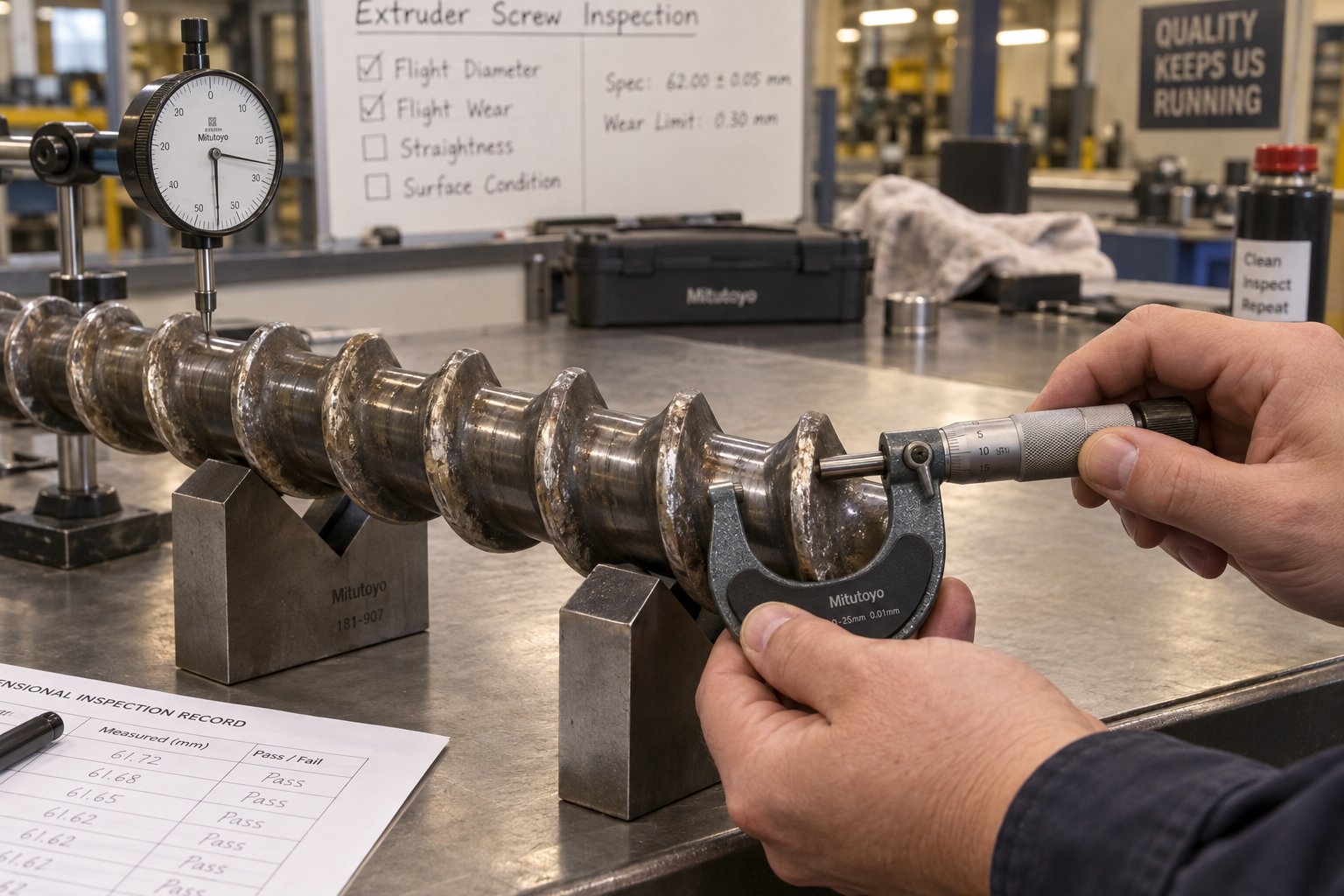
How to measure the damage. Before inspecting, remove all excess resin and place the screw on a clean, flat work surface. Examine the general condition — look for damage, pitting, or cracks. If a granite table is available, roll the screw and check for bowing; feeler gauges can quantify any bend. Then use a micrometer with a parallel test bar spanning two flights to measure the outside diameter at multiple points along the screw length. Record flight OD, root diameter, and flight width at regular intervals. For the barrel, a bore gauge inserted from each end captures the internal diameter. Compare every measurement to the original OEM specification or your baseline records from the last inspection.
The critical metric is flight clearance increase — the difference between the current radial gap and the original specification. As a reference, new flight clearance is typically the nominal screw diameter divided by 1000 per side. For a 3.5-inch extruder, that is roughly 0.0035 inches of clearance per side when new. Track the percentage increase over time, and you build a wear profile that predicts when replacement will become necessary — long before performance degrades to crisis levels.
Problem-Solution Matrix for Common Extrusion Issues
Wear does not announce itself with a warning light. It shows up as processing problems that operators struggle to explain — reduced output, rising melt temperatures, quality defects that appear gradually rather than all at once. The table below maps the most common symptoms to their likely extruder screw barrel wear causes and the solutions a qualified manufacturer would recommend.
| Processing Problem | Likely Wear Cause | Recommended Solution |
|---|---|---|
| Reduced output at constant RPM | Increased flight clearance allowing melt to leak backward over flight tips; screw unable to develop sufficient pumping pressure | Measure flight OD vs. barrel ID; rebuild flights with hardfacing or replace screw if clearance exceeds 4x original specification |
| Higher melt temperature than expected | Excessive leakage flow over worn flights generates additional shear heating; operator increases RPM to compensate for lost output, compounding the problem | Restore original flight clearance via screw rebuild or replacement; verify barrel bore is within tolerance |
| Poor melt quality (gels, unmelts, streaks) | Worn barrier flights or mixing elements losing undercut clearance; solid-bed fragments passing into the melt channel unchecked | Replace or rebuild mixing section and barrier flights; consider upgrading to a barrier screw if running a GP design |
| Output surging or pressure fluctuation | Root wear creating pockets where material hangs up and releases intermittently; inconsistent solids conveying in worn feed zone | Inspect root for wash-out and pitting; rebuild or replace affected zones; check barrel alignment |
| Material degradation (black specks, discoloration) | Root wear creating stagnation points where resin sits and thermally degrades; corrosive wear creating rough surfaces that trap material | Polish or rebuild root surfaces; evaluate metallurgy — switch to corrosion-resistant alloys if processing PVC or flame-retardant compounds |
| Increased energy consumption | Worn screw requires higher RPM to maintain output; motor works harder to overcome leakage flow losses | Track energy-per-pound metrics as a wear indicator; schedule rebuild when energy cost increase exceeds rebuild cost amortized over expected service life |
Notice the pattern: nearly every symptom ties back to clearance increase. As the radial gap between flight tips and barrel wall grows, leakage flow becomes inevitable. Material that should be conveyed forward instead slips backward over the flights, generating excessive shear and wasted energy in the process. The operator compensates with higher RPM, which raises melt temperature, which degrades product quality, which increases scrap rate. It is a vicious cycle — and the only way to break it is to restore the clearance through mechanical intervention.
Keep in mind that resin viscosity influences how quickly wear impacts performance. Higher-viscosity polymers like HDPE resist leakage flow better than lower-viscosity resins like PP. A flight clearance that causes negligible output loss on PE may produce significant rate reduction on PP under identical conditions. When processing shear-sensitive materials like PVC or polycarbonate, even minor wear creates disproportionate quality problems because the additional shear from leakage flow pushes the melt past its thermal stability limit.
When to Refurbish vs Replace Your Screw and Barrel
This is the decision that separates reactive maintenance from strategic maintenance. Pulling a screw and discovering it is worn is not the moment to start thinking about your options — it is the moment to execute a plan you have already made.
Refurbishment makes economic sense when the wear is moderate and the existing design is still appropriate for your process. An experienced manufacturer can rebuild worn screws to like-new condition for a fraction of the cost of a new screw and in less time. The process typically involves grinding the flights to a uniform undercut diameter, rewelding the flight tips with hardfacing alloy (such as Colmonoy 56 or a tungsten-carbide-loaded composition), then precision grinding the OD back to original tolerances. Improved hardfacing can even extend the rebuild's wear life beyond the original screw's.
Before committing to a rebuild, ask four questions:
- How severe is the overall wear — is enough base material left to support new hardfacing?
- What are the wear characteristics — is the root washed out, or is wear limited to the flight tips?
- Can the current screw design be significantly improved, making a new screw the better investment?
- Can the surface treatment be upgraded to extend service life in the next cycle?
There is a practical limit. Industry guidance from recognized authorities suggests a screw should not be refurbished more than three times, because each welding cycle deteriorates the base material and increases the risk of hardfacing delamination. That said, experienced screw manufacturers using high-quality welding techniques and careful metallurgical practices have rebuilt screws six to eight times successfully. The key variable is the quality of each rebuild, not an arbitrary number.
Replacement is the right call when wear is so severe that the root is washed out, when the existing design is poorly matched to your current resin or process requirements, or when the screw has been rebuilt multiple times and base-material integrity is questionable. It is also the better path when a redesigned screw — say, upgrading from a general-purpose geometry to a barrier design — would deliver enough throughput gain or energy savings to justify the higher upfront cost. Think of replacement not as a maintenance expense but as a process improvement opportunity.
For twin screw and barrel sets, the refurbish-vs-replace calculus tilts more heavily toward replacement of individual modular elements rather than rebuilding entire shafts. Worn kneading blocks, mixing elements, and conveying segments on a co-rotating twin can be swapped out individually, keeping the core shaft in service while replacing only the elements that have exceeded their wear limit. If you are evaluating a used twin screw extruder, pay special attention to element wear — the cost of replacing a full set of worn modular elements can approach the price of new shafts, which affects the true economics of the acquisition.
The barrel side follows similar logic. A standard nitrided barrel that has worn past tolerance is generally not rebuildable — it needs replacement. A bimetallic extruder barrel with a worn liner still has its outer shell intact and can sometimes be re-bored and re-lined, though this is specialized work that not all manufacturers offer. Barrel wear typically progresses at roughly one-third the rate of screw wear when an iron-based bimetallic liner is in place, meaning you can expect to go through approximately three screw service cycles for every barrel replacement.
The smartest maintenance programs treat screw inspection not as a reactive chore but as a data collection exercise — baseline measurements, tracked over time, that predict replacement timing and eliminate emergency downtime.
Knowing when to act is half the equation. The other half is knowing what standards to hold your manufacturer to when they deliver the rebuilt or replacement component — because a new screw that arrives out of tolerance or improperly hardened will wear right back to where you started.
Quality Control Standards Every Screw and Barrel Manufacturer Should Meet
A screw that looks right can still be wrong. Flight diameters might be off by a few thousandths of an inch. Hardness values might fall below the nitriding specification. A subtle bend invisible to the naked eye might cause the screw to wipe the barrel wall within weeks of installation. These defects do not announce themselves at the receiving dock — they reveal themselves later, as premature wear, erratic melt quality, or unexplained production losses that no amount of process tuning can fix.
This is why incoming inspection matters. Every screw you accept from any manufacturer — whether it is a brand-new custom build or a refurbished replacement — should arrive with measurable proof that it meets specification. If a supplier resists providing that proof, you have already learned something important about their quality system.
Critical Dimensional and Hardness Specifications
Five categories of measurement separate a properly manufactured screw from one that will cost you production time and barrel life.
Flight OD. The outside diameter of the flights determines your radial clearance against the barrel bore — and as the wear diagnosis section demonstrated, clearance is the single most important variable governing pumping efficiency, melt temperature, and output stability. Measure flight OD with an outside micrometer at four to six points along the screw length. The readings should match the drawing and remain consistent end to end. A taper — OD gradually shrinking from feed to discharge, or vice versa — indicates a grinding error during manufacturing. Even a few thousandths of variation can create uneven wear patterns that shorten both screw and barrel life.
Root diameter. Root measurements at the feed and metering zones verify the actual channel depths, which in turn confirm the compression ratio you ordered. A flight OD can be perfect while the root diameters are wrong, and you would never catch it visually — but your melt quality would tell you from day one. A micrometer or caliper over the root at both zones takes two minutes and eliminates any guesswork about whether the geometry matches the specification.
Overall and flighted length. Confirm both against the drawing. An incorrect overall length affects how the screw seats in the gearbox coupling and where the tip assembly indexes relative to the barrel discharge. An incorrect flighted length shifts every functional zone — feed, transition, metering — relative to the barrel's heating zones and feed opening, disrupting the thermal profile the process depends on.
Straightness. A bent screw destroys itself and your barrel. The standard verification method is straightforward: rest the screw on V-blocks or rollers near the ends, position a dial indicator on the flight OD near the center, and rotate slowly through 360 degrees. The total swing — highest reading minus lowest — is the total indicator reading (TIR). Repeat at two or three additional positions along the length; the worst reading governs acceptance. Typical specifications call for roughly 0.05 to 0.1 mm TIR per meter of screw length, though precise limits depend on the diameter and application. If the needle swings past the drawing tolerance, do not install the screw. A bent screw under rotation generates cyclic contact with the barrel wall that accelerates wear far beyond what any metallurgy can compensate for.
Hardness. This is the check most buyers skip — and the one that exposes the widest quality gap between manufacturers. A portable Leeb-type hardness tester applied to the flight tips and root surface reveals whether the nitriding, hardfacing, or heat treatment actually achieved its target values. For context, one Rockwell hardness point on the regular scale equals only 0.002 mm of indenter penetration depth — a measurement so precise that proper technique and calibrated instruments are essential for meaningful results.
What should you see? The answer depends on the construction:
| Construction Type | Where to Test | Expected Hardness Range |
|---|---|---|
| Nitrided 38CrMoAlA (or 4140/4340) | Flight tips and root surface | HV 850 - 1,100 surface; nitrided case depth 0.5 - 0.8 mm (verified via mill report) |
| Stellite or Colmonoy 56 hardfacing | Flight tips | Approximately HRC 50 - 55 |
| Colmonoy 83 / tungsten-carbide hardfacing | Flight tips | Approximately HRC 59 - 64 |
| Bimetallic barrel liner | Bore surface (if accessible) | HRC 58 - 65 depending on alloy grade |
Keep in mind that readings on curved, plated, or thin-cased surfaces carry some scatter. You are verifying the class of hardness — confirming that a nitrided screw is actually nitrided, that hardfacing is the grade specified — not auditing to a single decimal point. If you do not own a portable tester, request the hardness report before shipment. A manufacturer who measures hardness routinely will have one ready.
Two additional checks round out a thorough incoming inspection. Flight concentricity — measured by rotating the screw on centers and checking flight OD runout at multiple stations — ensures the clearance between screw and barrel is uniform around the full circumference. Eccentric flights create a tight spot on one side and a loose spot on the opposite side, guaranteeing uneven wear from the moment the screw starts turning. And surface finish on the flight lands and root should be smoothly polished. Melt flows directly over these surfaces, and roughness creates hang-up points where resin stagnates and thermally degrades — a particular concern for PVC and other heat-sensitive polymers.
Documentation and Certifications to Request
Measurements you take on the receiving dock verify the finished product. But a complete quality picture also requires documentation of what happened before the screw arrived — the raw material sourcing, heat treatment parameters, and in-process inspections that a professional manufacturer controls throughout production.
Here is what to ask for with every order:
- Material certificate (mill cert) — Confirms the steel grade, chemical composition, and heat number of the base material. This document traces the raw steel back to the mill and verifies that the screw is actually built from the alloy specified on the drawing — not a cheaper substitute.
- Heat treatment and nitriding records — Document the nitriding temperature, time, atmosphere, and resulting case depth and surface hardness. These parameters directly determine wear resistance. Without them, you are trusting that the heat treatment was done correctly with no way to verify after the fact.
- Dimensional inspection report — A point-by-point record of flight OD, root diameters, overall length, pitch, and shank dimensions measured against the approved drawing. This is the document that makes your receiving inspection a confirmation rather than a discovery.
- Hardness test results — Surface hardness values at multiple locations along the screw, measured with calibrated instruments and referenced to a recognized scale (Rockwell or Vickers). Should include the instrument calibration date and the test method used.
- Straightness / TIR record — The manufacturer's own measurement of total indicator reading, typically taken at multiple stations during or after final grinding.
If a manufacturer cannot produce these documents, that tells you more about their quality system than any brochure or website ever will. As one industry source put it plainly: the documentation is not bureaucracy — it is the difference between a supplier who measured and one who hopes.
A Buyer Quality Verification Checklist
Use the following step-by-step checklist every time you receive injection molding screws, extrusion screws, or injection molding screws and barrels from any supplier. It takes less than an hour with basic shop tools and catches the failures that would otherwise reveal themselves only after installation — at far greater cost.
- Inspect the paperwork first. Before touching the screw, confirm that the material certificate, dimensional report, hardness results, and heat treatment records arrived with the shipment. Missing documents mean missing accountability.
- Verify the shank and drive connection. Use a micrometer and thread gauge to confirm that the shank dimensions, keyway, and spline profile match your gearbox coupling. A misfit here is the most frustrating error to discover at installation time.
- Measure flight OD at four to six stations. Use an outside micrometer. Compare each reading to the drawing specification. Flag any taper or inconsistency exceeding the stated tolerance.
- Measure root diameters in the feed and metering zones. Calculate the actual compression ratio from the channel depths and compare to what you ordered.
- Confirm overall length and flighted length. Measure against the drawing using a tape or straight rule.
- Check straightness (TIR). Place the screw on V-blocks, set a dial indicator on the flight OD at center, and rotate 360 degrees. Repeat at two or three positions. Reject any screw that exceeds the drawing's TIR tolerance.
- Test surface hardness. Use a portable Leeb or Rockwell tester on flight tips and root. Compare values to the construction specification in the table above. If you lack a tester, cross-reference the manufacturer's hardness report against the stated alloy and treatment.
- Inspect surface finish and coatings. Run your eyes and fingers along the flights and root under good light. Polish should be smooth and uniform. Chrome plating, if specified, should show no pits, peeling edges, or dull patches. Hardfacing welds on flight tips should be continuous and ground flush — no visible porosity or cracks.
- Check for shipping damage. Note any dings, nicks, or dents on flight edges from handling. Document with photographs.
- Compare screw OD to your measured barrel bore. Calculate the actual running clearance. It should approximate the nominal screw diameter divided by 1,000 per side — matching the clearance your process was designed around.
Photograph every measurement setup and record the values in a log you keep alongside the manufacturer's inspection report. This baseline becomes invaluable later: when you pull the screw for its first maintenance inspection, comparing current measurements to the arrival baseline gives you an objective wear rate — not a guess — that feeds directly into your next replacement or refurbishment decision.
Quality benchmarks tell you whether a manufacturer delivered a good screw this time. The deeper question — whether they can deliver consistently, support you technically, and respond when problems arise — depends on how you evaluate and engage them from the very first inquiry.
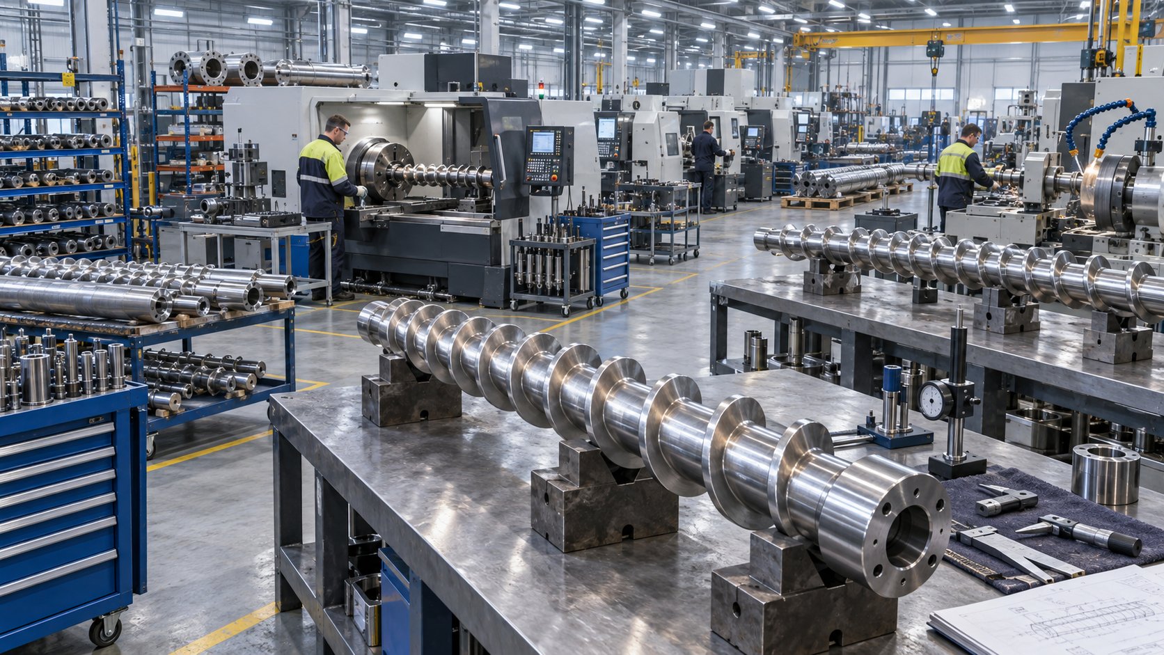
How to Evaluate and Engage a Screw Barrel Manufacturer
Inspection checklists and hardness reports protect you after the screw arrives. But the real risk management happens earlier — during the process of selecting which extruder manufacturer deserves your order in the first place. A supplier with excellent metallurgy and sloppy communication will cost you just as much downtime as one with poor steel. The engagement process, from the first email to final delivery, reveals more about a manufacturer's true capability than any catalog specification ever will.
Information to Prepare Before Contacting a Manufacturer
Walk into a conversation with incomplete information and you will get a generic quote. Walk in prepared and you give the manufacturer the raw material they need to engineer a real solution. Before reaching out to any extruders manufacturers on your shortlist, gather these details:
- Machine make, model, and year — Whether you run US extruders from brands like a Davis Standard extruder line, a European OEM, or an Asian-built machine, the manufacturer needs this to reference existing screw geometry databases and confirm barrel specifications.
- Screw diameter and L/D ratio — Measured from your current screw or pulled from the machine manual. If you are unsure of the L/D, provide the overall flighted length and diameter so the manufacturer can calculate it.
- Resin type, filler package, and additives — Include the specific polymer grade, percentage and type of any fillers (glass fiber, talc, calcium carbonate), and any additives such as colorants or flame retardants. This drives both the geometry recommendation and the metallurgy selection.
- Current processing issues — Quantify the problem wherever possible. "Output is down 12% at the same RPM" is far more actionable than "screw seems worn." Include melt temperature readings, specific energy data, and any quality defects you are seeing.
- Wear measurements — If you have pulled the screw, provide flight OD readings, barrel bore measurements, and photographs. These data points let the manufacturer diagnose root cause rather than guess.
- Previous screw design and metallurgy — Share whatever you know about the outgoing screw's construction: GP or barrier design, nitrided or hardfaced, base steel grade. This context prevents the manufacturer from simply duplicating a design that was already failing.
Presenting this package accomplishes two things. It accelerates the quoting process, and it immediately tests whether the manufacturer asks intelligent follow-up questions or simply prices the part without engineering discussion.
Evaluating Engineering Support and Lead Times
The quality of a manufacturer's response to your initial inquiry is one of the most reliable indicators of the quality you will receive in the finished product. Pay attention to how they handle the technical conversation — not just the price they quote.
- Engineering depth — Does the manufacturer ask about your resin, throughput targets, and processing history? Or do they simply request a drawing and return a number? A supplier who jumps straight to pricing without discussing application details is telling you they treat screws as commodity parts rather than engineered components.
- Design recommendations — A strong supplier will challenge your assumptions when appropriate. If you are reordering a GP screw that keeps wearing out on a glass-filled nylon application, the right manufacturer will recommend a barrier design with hardened flights — not silently build another screw destined to fail the same way.
- Lead time transparency — Standard replacement screws with common geometries typically ship in 15 to 25 working days from established manufacturers. Custom designs or complex twin-screw element sets can extend to 45 to 90 days. Be cautious of any supplier promising dramatically shorter timelines without explaining how — it may signal skipped heat treatment steps or insufficient QC.
- Communication responsiveness — Track how quickly they reply, how clearly they document technical discussions, and whether they proactively flag potential issues. A manufacturer who takes a week to answer a straightforward email will take longer when you need urgent support during a breakdown.
- Breadth of application experience — Manufacturers who serve both extrusion and injection molding platforms tend to possess deeper metallurgical and design expertise because they must solve a wider range of engineering problems across different process environments.
Request client references in your industry segment and, if possible, ask for a virtual or in-person factory tour. Seeing the CNC grinding centers, deep-hole boring machines, nitriding furnaces, and inspection equipment firsthand gives you a realistic picture of the operation behind the quote. A supplier's refusal to show their facility — live or via video — is a significant red flag that may indicate they are a trading company reselling another factory's output rather than manufacturing in-house.
Factory-Direct Sourcing and Its Advantages for Buyers
One of the most consequential decisions in your sourcing strategy is whether to buy through a distributor or go factory-direct. Each model has trade-offs, but factory-direct sourcing offers specific advantages that matter most for custom and replacement screw barrels.
Pricing transparency. Distributors add margin — typically 15% to 30% — for warehousing, logistics coordination, and customer service. When you buy directly from the factory that machines the screw, that margin disappears from your cost structure. For high-value custom orders or ongoing replacement programs, the savings compound quickly.
Customization flexibility. A distributor stocks what sells in volume. A factory builds what you specify. If your application requires a non-standard compression ratio, a specific hardfacing alloy, or a geometry modification to address a processing problem unique to your line, factory-direct communication eliminates the game of telephone between your engineering team and the people actually cutting metal.
Technical communication clarity. When your question about metallurgy or flight geometry reaches the engineer who designed the screw — rather than a sales intermediary summarizing it — answers are faster, more precise, and more likely to catch errors before they become expensive.
Chinese extruder manufacturers have become a major sourcing channel for processors worldwide, with regions like Zhoushan in Zhejiang Province and clusters in Jiangsu offering integrated supply chain ecosystems that include specialized raw material suppliers, heat treatment facilities, and bimetallic casting services all within close proximity. International buyers can typically achieve 30% to 60% cost savings compared to Western suppliers, though the key qualifier remains rigorous vetting — verifying that a potential supplier is a genuine manufacturer with in-house machining, heat treatment, and quality control rather than a trading company reselling parts of unknown origin.
As a concrete example of this factory-direct model, NANHAIYA supplies custom and replacement screw barrels directly to plastic processors, equipment builders, and maintenance teams for both extrusion and injection molding applications — illustrating the type of manufacturer that provides direct engineering access alongside manufacturing capability. This sourcing approach applies broadly: whether you work with a domestic US supplier, a European OEM partner, or a factory-direct Chinese manufacturer, the underlying evaluation criteria remain the same.
Regardless of geography, insist on the documentation standards outlined in the previous section — material certificates, dimensional reports, hardness records, and straightness verification. A factory-direct relationship gives you leverage to specify these deliverables contractually, and a manufacturer confident in their quality system will agree without hesitation. The ones who push back are telling you exactly where their quality system ends.
Frequently Asked Questions About Plastic Extruder Screw Manufacturers
1. What does a plastic extruder screw manufacturer actually do?
A plastic extruder screw manufacturer is a specialized engineering company that designs, CNC-machines, heat-treats, and supplies screws and barrels for extrusion and injection molding equipment. Their work goes beyond cutting metal — they analyze the buyer's resin type, filler package, throughput requirements, and processing challenges to engineer a screw geometry and select a metallurgy matched to those specific conditions. Services typically span custom screw design, barrel bore honing, nitriding or hardfacing surface treatments, and dimensional quality inspection. Suppliers like NANHAIYA (nhyscrews.com) offer factory-direct access to these capabilities for both extrusion and injection molding applications, giving processors direct communication with the engineers who build the components.
2. How do I choose between a single-screw and a twin-screw extruder for my application?
The choice depends primarily on your mixing requirements and feedstock complexity. Single-screw extruders excel at well-characterized, steady-state processes using pre-compounded resins — think PE pipe, blown film, or PVC profiles — offering lower capital cost and simpler maintenance. Twin-screw extruders provide superior mixing through intermeshing flight geometry, making them ideal for compounding, reactive extrusion, devolatilization, and processing recycled resins with variable contamination. Co-rotating twin screws deliver intense shear for compounding and masterbatch production, while counter-rotating configurations handle thermally sensitive materials like rigid PVC. Your configuration choice also narrows your manufacturer shortlist, since twin-screw element design requires different expertise than one-piece single-screw fabrication.
3. What metallurgy should I specify for my extruder screw and barrel?
Metallurgy selection depends on whether your primary threat is abrasion, corrosion, or both. For unfilled commodity polyolefins like PE and PP, standard nitrided 4140 or 4340 steel provides adequate wear life at the lowest cost. Glass-filled or mineral-loaded compounds require bimetallic barrels with tungsten-carbide-loaded liners and tool-steel flight tips (D2, H13, or CPM grades) to resist abrasive wear. Corrosive polymers like PVC and flame-retardant compounds demand nickel-alloy bimetallic liners and chrome-plated screw surfaces. Recycled resins with unknown contaminants call for the most robust metallurgy — typically bimetallic barrels paired with hardfaced screws — because the feedstock variability means your equipment must tolerate worst-case conditions rather than average ones.
4. How do I know when my extruder screw needs to be replaced or refurbished?
Monitor three key indicators: reduced output at constant RPM, rising melt temperatures without process changes, and quality defects such as gels, unmelts, or surface streaks. Physically, measure flight OD with a micrometer and barrel bore with a bore gauge at multiple stations, then compare against original specifications. The critical metric is flight clearance increase — when the radial gap exceeds roughly four times the original specification, pumping efficiency drops significantly. Refurbishment is cost-effective when wear is moderate and limited to flight tips, as hardfacing can restore and even improve the original wear life. Replacement becomes the better investment when root surfaces are washed out, the base material has been rebuilt multiple times, or the existing screw design is mismatched to your current resin or process requirements.
5. What quality documentation should I request from an extruder screw manufacturer?
Every order should arrive with five key documents: a material certificate (mill cert) confirming the steel grade and chemical composition, heat treatment and nitriding records documenting process parameters and resulting case depth, a dimensional inspection report with point-by-point measurements of flight OD, root diameters, and overall length, surface hardness test results at multiple locations along the screw, and a straightness or total indicator reading (TIR) record. These documents let you verify that the screw matches its engineering specification before installation. A manufacturer who cannot or will not provide this documentation is revealing a gap in their quality system that will eventually show up as premature wear or inconsistent processing performance on your production line.
Written by
Nanhaiya Technical Team
Zhoushan Nanhaiya Plastic Machinery Co., Ltd.
The Nanhaiya technical team supports screw and barrel manufacturing projects through application review, technical communication, custom manufacturing coordination, and production and quality control.
Discuss Your Application
Related Articles
More insights on screw barrel technology and plastics processing.

What Nobody Tells You About Screw Barrel For Plastic Machine Design
Oct 10, 2026
Learn how screw barrel for plastic machine design affects melt quality, throughput, and wear life. Covers geometry, resin matching, troubleshooting, and sourcing.
Read Article
Single Screw Extruder for Sheet: Stop Guessing, Start Specifying
Oct 9, 2026
Learn how to specify a single screw extruder for sheet production. Covers screw geometry, resin-specific processing, troubleshooting, and maintenance best practices.
Read Article
PE Pipe Extruder Machine: What Datasheets Won't Tell You
Oct 9, 2026
Learn how a PE pipe extruder machine works, key specs explained, material grade selection, maintenance tips, and buyer guidance beyond the datasheet.
Read ArticleLooking for something else?
Search by material, symptom or product and jump straight to the relevant page.
These are navigation suggestions based on keyword matching — not a quotation, not a delivery commitment, and not a substitute for engineering review. Final specification is confirmed by our engineers against your drawings and processed material.
Need help with screw barrel selection?
Share your machine model, processed material and application. Our team can help with pricing and technical support.