

Understanding Plastic Extruder Screw Barrel Repair
Imagine your extrusion line gradually losing output, your reject rate creeping upward, and your operators compensating with higher screw speeds and temperature adjustments they barely notice week to week. The root cause is often hiding in plain sight: worn screws and barrels quietly degrading the heart of your plasticating unit. The fix does not always demand a brand-new set of components. In many cases, a well-executed plastic extruder screw barrel repair restores — or even improves — original performance at a fraction of the cost and lead time.
What Plastic Extruder Screw Barrel Repair Actually Means
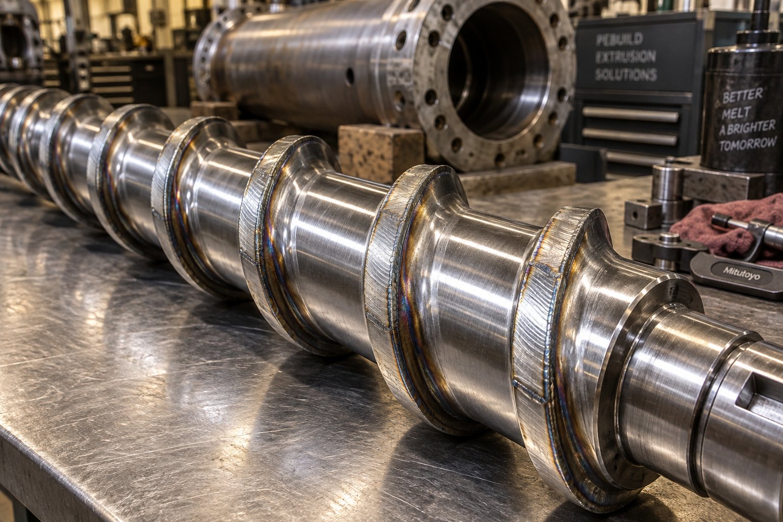
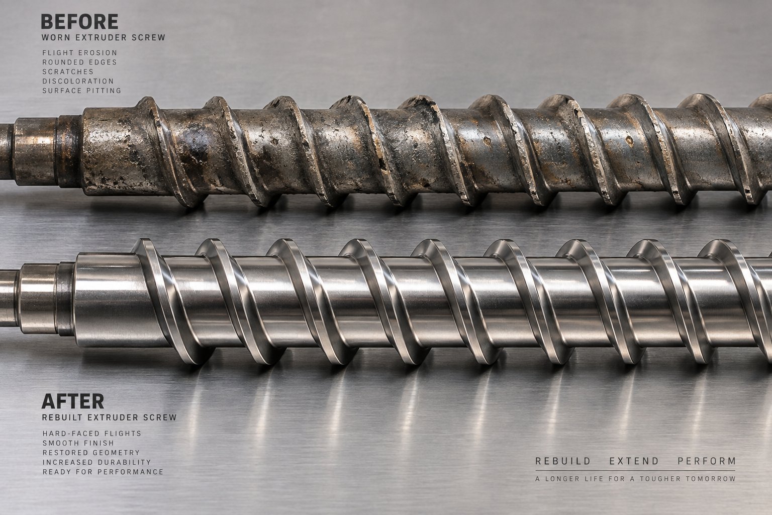
Plastic extruder screw barrel repair is the process of restoring worn, corroded, or damaged screws and barrels to their original dimensional tolerances and surface properties — or upgrading them with enhanced wear-resistant materials — rather than purchasing entirely new components. The work can range from welding new material onto eroded screw flights and grinding them back to specification, to honing or re-boring a barrel's inner diameter and applying fresh protective linings.
You'll notice the terms "repair," "rebuild," and "refurbishment" used almost interchangeably across the industry. There are practical distinctions worth understanding, though. Repair typically refers to correcting specific damage — rebuilding a section of worn flight lands, for instance. Rebuild implies a more comprehensive restoration that returns the full component to service-ready condition, often including dimensional re-machining and new surface treatments. Refurbishment sits somewhere between the two, addressing multiple wear areas without necessarily restoring every original dimension. Regardless of the label, the goal is the same: extend useful life and reclaim the tight clearances between screw flight outside diameter and barrel bore that drive efficient melting and conveying. As Plastics Technology notes, those clearances are usually minimal — around 0.001 in. per side per inch of diameter — and even small increases from wear degrade heat transfer, shear rate, and overall plasticating efficiency.
Why Repair Matters for Extrusion Operations
The economic case for repair over outright replacement is compelling, especially for larger-diameter screws and barrels where new components carry significant price tags and extended delivery windows. Repair costs commonly land between 30% and 50% of new-component pricing, and turnaround times are often measured in days rather than the weeks or months a new build may require. For a plant running tight production schedules, that difference in downtime alone can justify the decision.
A single screw and barrel replacement on a large extruder can cost several times more than a professional rebuild — and the rebuilt unit, when done correctly with upgraded surface alloys, may actually outlast the original components in the same application.
Beyond the direct cost savings, repair opens a door that simple replacement does not: the opportunity to upgrade. During a rebuild, worn flight surfaces can be restored with harder, more corrosion-resistant alloy overlays than the original manufacturer specified. A barrel re-bored to a slightly larger diameter can be paired with a matched oversized screw, effectively giving you a refreshed plasticating unit engineered for your current resin portfolio rather than the one the machine was first sold to process.
This guide covers both extrusion and injection molding applications, since the core screw-and-barrel repair techniques overlap substantially. Where procedures or decision criteria differ between the two — barrel length considerations, non-return valve components unique to injection molding, or the continuous-duty wear patterns of extrusion versus the cyclic loading of injection — those distinctions are called out in the relevant sections ahead.
What follows is a complete technical walkthrough: from recognizing the earliest symptoms of wear, through diagnosing root causes and selecting the right repair method, to verifying quality after reinstallation. The objective is straightforward — equip you with enough knowledge to make confident, cost-effective decisions and avoid the scenario the title warns about: paying twice because the first repair was done wrong.
Warning Signs Your Extruder Screw and Barrel Need Repair
Recognizing wear early is what separates a manageable, cost-effective repair from an emergency rebuild that halts production for days. The tricky part? Screw and barrel wear rarely announces itself with a single dramatic event. Instead, it creeps in through subtle shifts in output, process stability, and part quality — changes operators often compensate for without realizing the underlying cause. Knowing exactly which symptoms to watch for, and understanding the mechanism behind each one, lets you act before the damage escalates.
Output and Quality Symptoms That Signal Wear
Declining throughput is frequently the first measurable sign that something is wrong. As the clearance between the screw flight outer diameter and the barrel bore widens, molten polymer leaks backward over the flights instead of being pushed forward. This backflow — sometimes called "leakage flow" — directly reduces the extruder's pumping efficiency. You might initially compensate by increasing screw speed, but that introduces a second problem: higher discharge temperatures from the added shear and reduced heat-transfer efficiency at the barrel wall. Data from Plastics Technology illustrates this clearly — on a 100 mm screw processing polyethylene, progressive wear forced a screw speed increase that pushed discharge temperatures roughly 10°C higher, eventually making the line unable to hold rate without exceeding thermal limits for the downstream process.
Beyond raw throughput, watch for these quality-related red flags:
- Inconsistent melt temperature: Wider flight clearances disrupt the uniform shear pattern the screw was designed to deliver, causing shot-to-shot or moment-to-moment melt temperature swings.
- Poor color dispersion and streaking: Worn mixing sections or reduced compression in the transition zone fail to develop the shear needed for thorough pigment or additive distribution.
- Unmelted pellets or gels in the extrudate: When the screw's compression ratio effectively drops due to flight wear, solid-bed breakup becomes inconsistent — some material passes through without fully plasticating.
- Increased reject rates: Dimensional variation in pipe, sheet, or profile output often traces back to melt pressure instability caused by screw wear, not die or calibration issues.
- Black specks or burn marks: Material degradation inside dead zones created by clearance gaps leads to carbonized buildup that periodically flushes into the product stream — a common issue with recycled plastics, PVC, and high-temperature resins.
The key takeaway here is that each of these extruder screw wear symptoms signals declining output and quality for a specific mechanical reason. Addressing the symptom without diagnosing the root cause — adjusting temperatures, slowing the line, tightening the die gap — only delays the inevitable and often makes the eventual repair more extensive.
Mechanical and Electrical Warning Signs
Your machine's electrical and mechanical behavior tells a parallel story. Rising motor amperage under the same processing conditions — same resin, same screw speed, same barrel setpoints — is one of the most reliable early indicators. As wear progresses, the screw must work harder to convey and pressurize material through a less efficient geometry. A 10-20% increase in energy consumption per ton of output, compared to historical baselines, strongly suggests internal wear has crossed from marginal to significant.
Other mechanical and electrical warning signs include:
- Unusual vibrations or noise: An out-of-balance screw, barrel ovality from uneven wear, or non-uniform flight erosion can all produce vibration patterns that were absent when components were new. Left unchecked, these vibrations accelerate bearing and gearbox wear.
- Difficulty maintaining setpoint temperatures: When a single barrel zone consistently runs hotter than its setpoint despite functioning heaters and cooling, the likely explanation is changed heat-transfer characteristics from localized barrel bore wear or scoring. As MachineCDN's predictive maintenance analysis explains, a zone running 8°F or more above its historical average — while neighboring zones remain stable — points to barrel wear altering the thermal profile in that section.
- Excessive temperature differentials between zones: A healthy barrel maintains relatively consistent heater duty cycles across zones. When one zone's heaters run at near-100% duty while adjacent zones cycle normally, suspect worn or scored bore surfaces changing the local thermal dynamics.
- Melt pressure instability: Steady-state melt pressure should vary less than roughly ±50 PSI during stable operation. Pressure swings larger than this — particularly slow, cyclical oscillations — often indicate screw wear causing inconsistent solid-bed conveyance.
Tracking these parameters over time, even with basic data logging from the machine's existing PLC, builds a wear curve specific to your screw, barrel, and material combination. That historical trend is far more valuable than any single measurement.
Visual Inspection Indicators During Scheduled Downtime
When you pull the screw during a scheduled shutdown, you have a direct window into what is actually happening inside the barrel. This is the most definitive way to tell if your extruder barrel is worn and to gauge whether the damage is repairable or has progressed beyond practical limits.
Here is what to look for systematically:
- Scoring along flight lands: Longitudinal scratches or grooves on the flight tips indicate metal-to-metal contact, often from misalignment or momentary solid-bed blockages forcing the screw against the barrel wall.
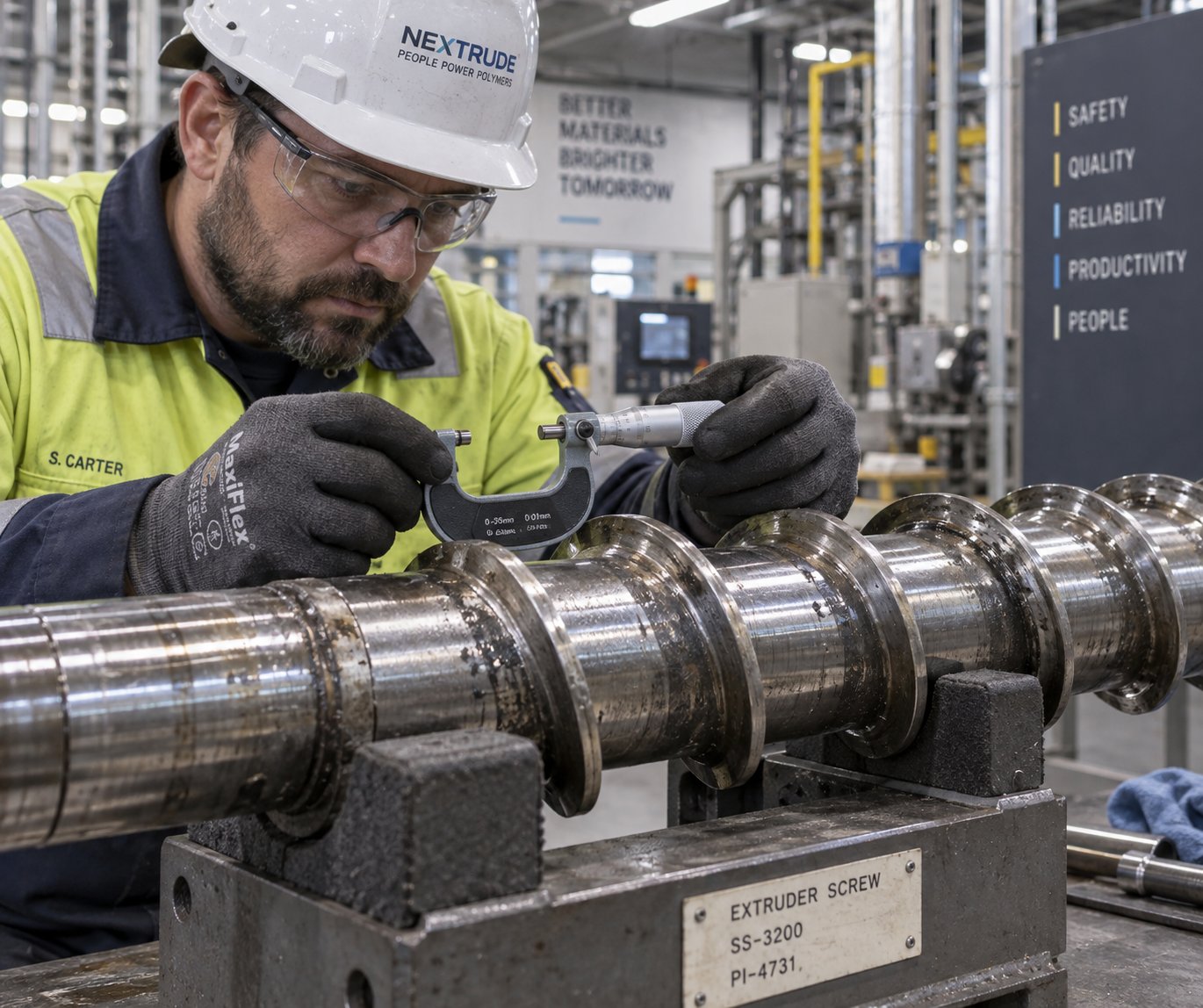
- Reduced flight height: Measure the screw flight outside diameter at multiple points along the length. Industry practice flags a screw for repair when flight clearance reaches roughly two to four times the original specification. A screw designed with 0.004 in. clearance per side, for instance, should be evaluated once clearance approaches 0.008-0.016 in.
- Pitting on the barrel bore: Small craters or rough patches inside the barrel indicate corrosive attack, typically from acidic degradation gases generated by PVC, flame-retardant compounds, or moisture-reactive resins.
- Discoloration and surface staining: Heat tinting or chemical discoloration distinct from normal polymer residue suggests corrosive exposure that may have compromised the barrel liner or nitrided surface layer.
- Cracking at high-stress transition zones: Inspect the flight roots — especially at the transition between the feed and compression sections — for hairline cracks. Cyclic stress from processing high-viscosity materials at elevated pressures concentrates at these points, and fatigue cracks can propagate quickly once initiated.
- Worn or missing hard facing on flight tips: Hard facing is typically about 0.060 in. thick on new screws. If it has worn through to the base metal, the wear rate will accelerate dramatically because the softer substrate erodes far faster.
A practical rule reinforced by experienced rebuilders: a screw should generally not be refurbished more than three times, because repeated weld cycles degrade the base metal and increase the risk of delamination between hard facing and substrate. Documenting each inspection with measurements and photographs creates the baseline you will need when discussing repair scope with your service provider.
Early detection across all three categories — output symptoms, mechanical indicators, and direct visual evidence — consistently reduces both the scope and the cost of repair. A flight rebuild caught at moderate wear is a straightforward weld-and-grind job. The same screw left in service until hard facing is gone entirely may need complete flight replacement or, worse, may not be economically repairable at all. The patterns you observe during inspection also point toward the specific wear mechanism at work — and identifying that mechanism is the essential next step in choosing the right repair approach.
Four Wear Mechanisms and How to Identify Each One
Spotting the symptoms is only half the picture. A scored flight tip and a pitted barrel bore both mean something is wrong, but they point to very different underlying causes — and each demands a different repair strategy. Choosing the wrong fix because the wear mechanism was misidentified is one of the fastest ways to pay for the same repair twice.
Every type of wear on plastic extruder screws and barrels traces back to one of four fundamental mechanisms: adhesive, abrasive, corrosive, or mechanical fatigue. Some components suffer from a single dominant mechanism; others experience two or three simultaneously, which complicates diagnosis. Understanding what each mechanism looks like, where it shows up, and which polymers tend to trigger it gives you the information you need to match the damage to the most effective — and most cost-efficient — repair approach.
Adhesive and Abrasive Wear Patterns
Adhesive wear happens when two metal surfaces make direct contact under high pressure. Picture the screw flight tip pressing against the barrel bore during rotation. Under normal operation, a thin layer of molten polymer separates the two surfaces and prevents metal-to-metal contact. When that melt film is disrupted — by misalignment, solids wedging, or a screw design mismatch — localized contact welds form and immediately fracture as the screw continues turning. The result is material transfer from one surface to the other, leaving behind distinctive galling marks, burrs rolled over the trailing edge of flight lands, and scoring inside the barrel at the corresponding location.
You'll typically find adhesive wear concentrated in areas where mechanical forces push the screw off-center: the metering zone under high back pressure, or the transition zone where incompletely melted solids can wedge the screw sideways. As Glycon's Jeff Kuhman explains, when the melting section's capacity falls short of the feed section's delivery rate, unmelted material plugs the channel and generates enough lateral force to press the screw against the barrel wall — a condition called solids wedging that aggressively galls both the flight land and the barrel inner surface. Incompatible metallurgies between the screw hard facing and the barrel liner material make the problem worse, because softer alloys have a greater tendency to gall against harder surfaces.
Abrasive wear is arguably the most common wear mechanism in plastics processing. It occurs whenever hard particles in the melt stream grind against softer metal surfaces — essentially a continuous sandblasting effect from the inside. Those hard particles can be intentional fillers like glass fibers, calcium carbonate, talc, or mineral additives, or they can be unintentional contaminants such as metal fragments, grinder blades, or delaminated hard-facing material that has broken loose from the screw itself.
The signature of abrasive wear is progressive, relatively uniform material loss. Flight lands thin out evenly along their length rather than showing isolated gouges. The barrel bore gradually enlarges, increasing the critical flight-to-bore clearance. Extruder screw abrasive wear from glass fiber or mineral fillers is especially severe because these particles are harder than most standard screw steels. Industry data shows that some of the most aggressive fillers can reduce screw and barrel useful life by 50% or more compared to processing unfilled polymers. Glass- and mineral-filled resins also attack the screw root in the rear of the channel — before the additive fully wets out and mixes with molten plastic — creating localized erosion that is easy to overlook during a quick visual inspection.
Corrosive and Mechanical Fatigue Damage
Corrosive wear looks nothing like abrasive wear under close examination, and confusing the two leads directly to misguided repair decisions. Corrosion is a chemical attack on the metal surface rather than a mechanical grinding action. Most of the atoms on the affected surface are oxidized, creating widespread pitting, roughened textures, and a general degradation of the protective surface layer — whether that layer is a nitrided case, a bimetallic liner, or a hard-facing alloy.
Corrosive wear on barrel bore surfaces during PVC processing is a textbook example. When PVC degrades thermally, it releases hydrochloric acid gas that aggressively attacks components with high iron content. Fluoropolymers such as PVDF and PTFE, flame-retardant-loaded resins, and moisture-sensitive engineering plastics that undergo hydrolysis all generate similarly corrosive byproducts. The visual clues are distinctive: rather than the smooth, polished-away surfaces of abrasive wear, you'll see irregular pitting, a roughened or "orange peel" texture, and sometimes dramatic discoloration where chemical reactions have altered the surface chemistry.
The critical implication for repair is that corrosion compromises the base metal's integrity at a microscopic level. Simply welding a hard-facing overlay onto a corroded surface without first removing all compromised material risks poor bond adhesion and premature failure. Corrosion-resistant alloy overlays — not just hard coatings — are essential when the repaired component will return to processing the same corrosive resin family.
Mechanical fatigue is the least visible and most dangerous of the four mechanisms. Unlike adhesive, abrasive, or corrosive wear, fatigue does not remove material from the surface. Instead, it initiates and propagates cracks internally through repeated cyclic loading. Every screw rotation subjects the flight roots to alternating bending stresses, and every pressure pulse from the extrusion or injection process adds another load cycle to the tally.
Mechanical fatigue cracking on extruder screw flights tends to concentrate at the highest-stress geometric transitions — flight roots in the compression zone, the junction between the feed and transition sections, and around mixing-element features where cross-sectional changes create stress risers. Screws processing high-viscosity materials at elevated pressures accumulate fatigue damage fastest because each cycle imposes higher stress amplitudes. The telltale sign is hairline cracks at the base of the flights, sometimes visible only under dye-penetrant inspection or magnetic particle testing, not casual observation.
Fatigue damage is uniquely challenging from a repair standpoint. Welding over a fatigue crack does not eliminate the crack tip — it simply buries it beneath new material, where it can continue propagating under service loads. If cracks have grown beyond a certain depth, or if they appear at multiple flight roots, the screw is typically not a candidate for economical repair and should be replaced.
Matching Wear Type to Repair Approach
Identifying the correct mechanism — or combination of mechanisms — is what transforms a plastic extruder screw barrel repair from a guess into an engineered solution. The table below maps each wear type to its visual fingerprint, the zones where it typically appears, the polymers most likely to cause it, and the repair category that addresses it effectively.
| Wear Mechanism | Visual Indicators | Typical Location | Common Polymer Culprits | Recommended Repair Category |
|---|---|---|---|---|
| Adhesive | Galling marks, burrs on flight trailing edge, scoring on barrel bore, material transfer between surfaces | Metering zone, transition zone (especially where solids wedging occurs) | Any polymer under misalignment conditions; high-viscosity resins that disrupt melt film | Re-surface flight lands with compatible hard-facing alloy; correct alignment; evaluate screw/barrel metallurgical compatibility |
| Abrasive | Uniform thinning of flight lands, progressive bore enlargement, root erosion in feed channels | Flight tips and barrel bore along full length; screw root in feed/transition zone | Glass-fiber-reinforced nylon, mineral-filled polyolefins, calcium carbonate compounds, recycled resins with contaminants | Hard-surface weld rebuild (PTA, alloy spray) with high-carbide overlays; re-bore barrel and match with oversized screw if needed |
| Corrosive | Irregular pitting, roughened "orange peel" texture, discoloration, degraded nitrided or bimetallic surface layer | Metering zone and compression zone where melt temperatures are highest; barrel bore throughout heated zones | PVC, PVDF, fluoropolymers, flame-retardant-loaded resins, moisture-reactive engineering plastics | Remove all compromised material, then apply corrosion-resistant alloy overlay (nickel-based or cobalt-based); avoid carbon-steel hard facing alone |
| Mechanical Fatigue | Hairline cracks at flight roots (may require dye-penetrant or magnetic particle inspection), fracture surfaces at geometric transitions | Flight roots in the compression zone, feed-to-transition junction, mixing element features | High-viscosity engineering resins processed at elevated pressures (e.g., PC, PMMA, high-MW HDPE) | Evaluate crack depth and extent; shallow, isolated cracks may allow localized repair; extensive cracking typically requires screw replacement rather than repair |
A few practical points stand out from this framework. First, many real-world screws and barrels exhibit combined wear — a glass-filled, flame-retardant nylon, for instance, delivers abrasive and corrosive attack simultaneously. The repair plan must address both mechanisms, which usually means selecting an overlay alloy that combines high hardness with corrosion resistance rather than optimizing for just one property.
Second, the wear type directly dictates the repair material, not the other way around. Applying the hardest available carbide overlay to a screw suffering primarily from corrosive attack is a common and expensive mistake — carbide alloys can be brittle and may lack the chemical resistance needed to survive in a PVC or fluoropolymer environment. The repair material must be chosen to counter the dominant degradation mechanism your specific process creates.
Third, fatigue cracking occupies a unique position in this framework because it is the one mechanism that most often tips the decision from repair toward replacement. Adhesive, abrasive, and corrosive damage are all surface phenomena that modern rebuild techniques handle well. Fatigue is a bulk-material failure that cannot always be reversed — and attempting to repair a fatigue-compromised screw without thorough non-destructive testing is a gamble with high stakes.
Of course, the polymer you process does not just determine which wear mechanism dominates. It also shapes which alloys, coatings, and surface treatments will survive in service after the repair is complete — a relationship that becomes critical when selecting specific repair materials and techniques.
How Polymer Types Drive Different Repair Strategies
The resin running through your extruder is not just a product — it is the single biggest factor determining how your screw and barrel wear, where that wear concentrates, and which repair materials will actually survive once the rebuilt component goes back into service. Two processors can operate identical machines on the same production schedule, yet one pulls the screw for repair in 18 months while the other gets five years of trouble-free running. The difference almost always traces back to what they are processing.
Matching the repair strategy to the polymer family is where many rebuilds go wrong. A shop that applies the same hard-facing alloy to every screw regardless of the customer's resin is essentially guessing — and that guess frequently costs the operator a second repair within a fraction of the expected service life. Understanding polymer-specific wear profiles turns that guesswork into engineering.
Abrasive Polymers and Glass-Filled Compounds
Glass-fiber-reinforced nylon, mineral-filled polyolefins, calcium-carbonate-loaded compounds, and ceramic masterbatches are among the most demanding materials a screw and barrel will ever face. The hard particles embedded in these resins act like an internal grinding wheel, steadily eroding flight tips, barrel bore surfaces, and even screw root channels in the feed and transition zones. Industry experience confirms that some of the most aggressive fillers can cut screw and barrel useful life by 50% or more compared to processing unfilled resins.
Screw barrel repair for glass-filled nylon processing — or any heavily filled compound — demands the hardest available surface coatings during the rebuild. High-tungsten-carbide overlays applied through plasma transfer arc (PTA) welding or alloy spray processes deliver the abrasion resistance these applications require. However, the original screw and barrel construction matters just as much as the repair material. Consider these scenarios:
- Nitrided steel screws: The nitrided case is typically only 0.010-0.020 in. deep. Once abrasive wear penetrates that case, the softer base metal erodes rapidly. Repair options include stripping the remaining case, building up with a carbide-rich weld overlay, and grinding back to dimension — but the base metal must be sound enough to accept the weld without cracking.
- Bimetallic barrels: Centrifugally cast liners with high tungsten carbide content provide excellent initial wear resistance. When the liner wears through, the barrel can often be re-bored to a larger diameter and paired with a matched oversized screw, but if the liner has worn completely into the backing material, a full liner replacement may be necessary.
- Tool steel overlays: Screws originally built with tool steel flight hard facing accept re-welding relatively well, provided the existing overlay has not delaminated or developed subsurface cracks from fatigue. Compatibility between the original and new alloy layers is critical to avoid delamination during service.
The takeaway is straightforward: abrasive-resin applications demand repair materials selected specifically for hardness and erosion resistance, and the viability of the repair depends heavily on what the original component was made from.
Corrosive Resins and Thermally Sensitive Materials
Corrosive polymers present a fundamentally different challenge. PVC releases hydrochloric acid during thermal degradation. Fluoropolymers such as PVDF emit hydrofluoric acid — one of the most aggressive chemicals any metal surface will encounter. Acetal generates formic acid. Flame-retardant-loaded resins produce halogenated byproducts that attack metal surfaces chemically rather than mechanically. As Nanjing Haisi's technical overview explains, standard screws and barrels made of nitrided steel, tool steel, or alloy steel are vulnerable to this acid attack and can deteriorate rapidly under corrosive processing conditions.
Here is the costly mistake many operators make: they treat corrosion damage the same way they treat abrasive wear and specify a hard carbide overlay for the repair. Carbide-rich alloys deliver excellent abrasion resistance but often lack the chemical inertness needed to survive in a PVC or fluoropolymer environment. The rebuilt flights look perfect on delivery, then pit and degrade within months because the overlay itself is susceptible to the same acidic attack that destroyed the original surface.
Effective PVC extruder screw corrosion repair solutions require nickel-rich, corrosion-resistant alloy layers — materials like Colmonoy 56 or Colmonoy 83 that resist acid attack at the molecular level rather than relying purely on hardness. Bimetallic barrel liners with nickel-boron alloy bases incorporating molybdenum, borides, and carbides offer dual protection against both corrosion and moderate abrasion. For barrels, replacing a corroded liner with a corrosion-rated centrifugal casting is often more effective than attempting to patch the existing liner.
High-Temperature Engineering Plastics
PEEK, PEI (Ultem), PPS (Ryton), and similar high-performance polymers push barrel temperatures to 350-400 degrees Celsius or higher — well above the range where standard repair materials maintain their properties. PEEK alone has a melting point of approximately 343 degrees Celsius, and actual processing temperatures often exceed that to achieve adequate melt flow, particularly with filled grades.
These sustained elevated temperatures introduce thermal stress patterns that compound conventional wear. Repeated heating and cooling cycles cause differential thermal expansion between the screw, barrel, and any applied coatings. If the repair material's coefficient of thermal expansion does not closely match the base metal, the overlay can crack, delaminate, or spall during service — a failure mode almost never seen at conventional polyolefin processing temperatures. Finding the best repair material for high-temperature plastics extrusion means selecting alloys specifically rated for sustained service at these extremes, not simply choosing the hardest option available.
Thermal expansion mismatch also affects barrel-to-screw clearances at operating temperature. A clearance set perfectly at room temperature during the repair shop's final inspection may tighten dangerously at 380 degrees Celsius if the screw and barrel expand at different rates. This is why experienced repair providers factor in thermal expansion data when setting final dimensions for high-temperature applications.
To consolidate these polymer-specific wear profiles into a practical reference, here is a summary linking each major resin family to its dominant wear mechanism, where the damage typically appears, and the repair material class that addresses the problem effectively:
- Glass-fiber-reinforced nylon (PA6-GF, PA66-GF): Primary mechanism is abrasive wear. Concentrates on flight tips, barrel bore, and screw root in the feed zone. Repair with high-tungsten-carbide weld overlays or carbide-rich thermal spray coatings.
- Mineral-filled polyolefins (PP + talc, PE + CaCO3): Moderate abrasive wear, distributed along the full screw length. High-hardness alloy spray or PTA overlays restore service life effectively.
- PVC (rigid and flexible): Dominant mechanism is corrosive attack from hydrochloric acid. Affects the metering zone and compression zone most heavily. Demands nickel-based corrosion-resistant alloy overlays on both screw and barrel surfaces.
- Fluoropolymers (PVDF, PTFE, FEP): Severe corrosive wear from hydrofluoric acid. Attacks all heated zones aggressively. Requires the highest-grade corrosion-resistant liners and coatings — standard alloys fail quickly.
- Flame-retardant compounds (various base resins): Combined abrasive and corrosive wear from halogenated additives and hard filler particles. Repair material must balance hardness with chemical resistance — a pure carbide overlay is insufficient.
- PEEK, PEI, PPS: Thermal stress and moderate abrasive wear (especially with filled grades). Repair materials must be rated for sustained service above 350 degrees Celsius with matched thermal expansion coefficients.
- Recycled and post-consumer resins: Unpredictable abrasive wear from contaminants (metal fragments, paper, sand). Versatile high-hardness overlays paired with frequent inspection intervals offer the most practical approach.
Selecting the wrong repair material for the polymer being processed is one of the most common — and most expensive — mistakes in screw and barrel rebuilding. A hard coating that ignores corrosion, or a corrosion-resistant layer that cannot withstand abrasion, delivers a component that looks perfect on the bench but fails prematurely in the machine.
The polymer-specific profiles above highlight a critical reality: the repair technique itself is only as good as the material chosen to execute it. That connection between technique and material leads directly to the question of which rebuild methods — welding, coating, machining, and their many variations — deliver the best results for each type of damage.
Major Repair Techniques Compared in Detail
Knowing which wear mechanism is at work and which polymer caused it only gets you halfway to a successful repair. The other half is choosing the right technique to deposit, coat, or machine the component back to specification. Each method has distinct strengths, cost implications, and limitations — and picking incorrectly is one of the most reliable ways to end up paying for the same job twice.
Repair techniques fall into three broad categories: weld-based methods that rebuild lost material, surface treatments that restore protective layers without adding significant thickness, and machining operations that bring everything back to precise dimensional tolerances. Most real-world repairs combine elements from all three.
Weld-Based Rebuild Methods
When flight lands have worn thin, root channels have eroded, or barrel surfaces have lost material beyond what a coating alone can recover, weld-based rebuilds are the foundation of the repair. These processes deposit wear-resistant alloy onto the worn surfaces, effectively creating a new working layer that can meet or exceed original specifications.
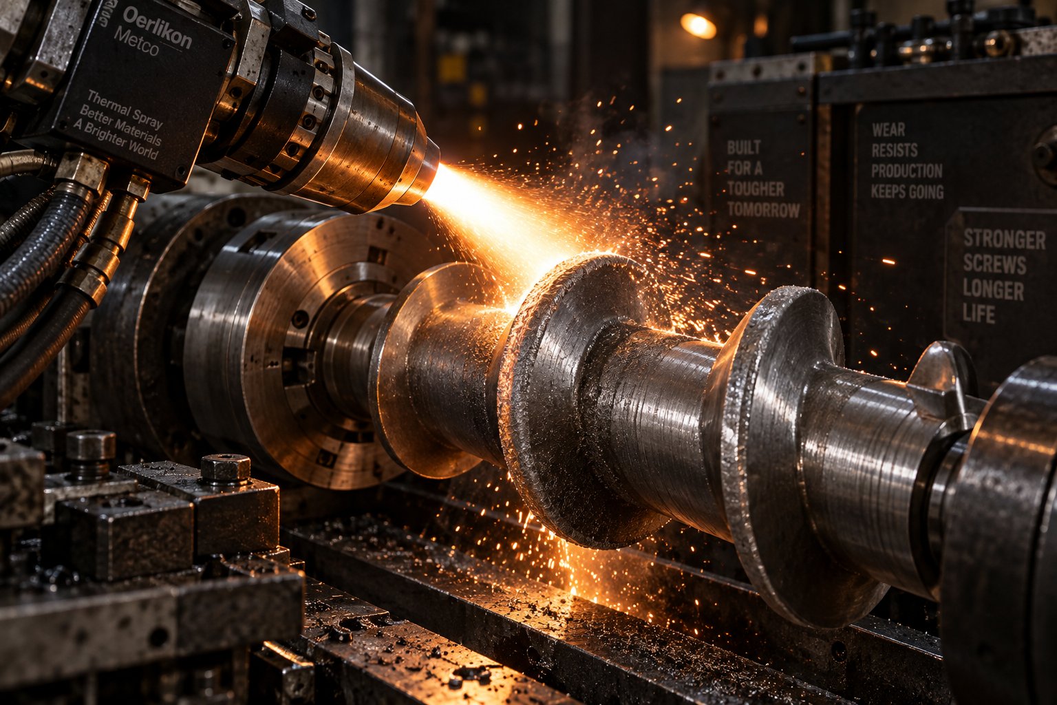
Alloy spray welding is among the most versatile options. The process uses a thermal spray gun to deposit a fine layer of alloy powder — typically nickel-based, cobalt-based, or iron-based compositions loaded with carbide particles — onto the screw flight tips or barrel bore. Deposition thickness typically ranges from 1 to 3 mm, making it suitable for moderate to heavy wear patterns. Bond strength is excellent when surfaces are properly prepared, and the technique accommodates a wide range of alloy chemistries, letting the repair shop match the overlay to the specific wear mechanism at play. Providers like NANHAIYA offer alloy spray welding services tailored to both extrusion and injection molding operators, addressing wear, corrosion, and service-life challenges through application-specific alloy selection and wear-resistant surface treatments. This kind of flexibility is exactly what makes alloy spray welding for extruder screw repair a go-to method across polymer types — from glass-filled engineering resins to corrosive PVC compounds.
Plasma Transfer Arc (PTA) welding delivers the highest-quality metallurgical bond of any screw rebuild process. A transferred plasma arc melts a thin layer of the base metal surface while simultaneously feeding powdered alloy into the weld pool, fusing the overlay directly to the substrate. Research published in The Paton Welding Journal demonstrates that PTA surfacing on screw flight tips deposits a 1-2 mm layer of wear- and corrosion-resistant alloy with minimal base metal dilution. The same study found that PTA-repaired screws achieved 3 to 5 times the service life of new nitrided screws — a remarkable performance gain from a repair process. The technique does require specialized equipment and precise parameter control, particularly on small-diameter screws where the narrow flight width (sometimes only 3-4 mm) demands careful management of weld pool length and arc current to prevent molten metal from dripping off the flight edge.
Manual and automated hard facing covers traditional MIG, TIG, and submerged arc weld overlay processes. These screw flight hard facing weld overlay processes deposit material onto worn flight tips using consumable wire or rod electrodes. Manual hard facing is accessible and cost-effective for localized repairs, but the heat input is higher than PTA or spray welding, which increases the risk of distortion on long, slender screws. Automated hard facing — using a lathe-mounted torch and programmed feed rates — improves consistency and reduces operator dependence. Typical overlay thickness ranges from 1.5 to 4 mm before final grinding.
Surface Treatment and Coating Techniques
Surface treatments differ from weld-based methods in a critical way: they restore protective surface properties without rebuilding lost geometry. Think of them as the finishing layer applied after — or sometimes instead of — a weld rebuild, depending on the severity of wear.
Re-nitriding restores the hard, nitrogen-diffused case on the screw surface that wears away during service. The process exposes the screw to a nitrogen-rich atmosphere at elevated temperatures, re-creating a hardened layer typically 0.010 to 0.020 in. deep. Nitriding is effective only when the screw's base metal still retains enough dimension — it adds hardness, not material. For screws that have been weld-rebuilt, nitriding the finished surface adds an additional wear-resistant barrier on top of the overlay.
Re-chroming applies a thin layer of hard chromium to screw or barrel surfaces through electroplating. Chrome layers improve surface hardness and reduce friction, but maximum practical thickness is limited to roughly 0.010 to 0.015 in. It is best suited for screws with minimal dimensional loss that primarily need surface protection rather than material replacement. Note that hard chrome plating carries environmental considerations — hexavalent chromium (Cr6+) is a regulated hazardous material under EPA NESHAP, and many facilities are actively transitioning away from chrome toward thermal spray alternatives.
HVOF and HVAF thermal spray coatings represent the high-performance end of surface treatments. High Velocity Oxy-Fuel (HVOF) thermal spray coating for extruder barrel or screw surfaces propels tungsten carbide or chromium carbide particles at supersonic speeds onto the substrate, creating an extremely dense, well-bonded coating. HVOF coatings achieve hardness values of 900 to 1,100 HV with porosity between 1 and 2%, while the newer HVAF (High Velocity Air-Fuel) variant pushes hardness to 1,100 to 1,400 HV with porosity below 0.5% by using compressed air instead of oxygen — preserving the carbide microstructure that partially dissolves in HVOF's higher flame temperatures. Typical deposit thickness runs 0.020 to 0.040 in., making these coatings ideal for restoring barrel bore surfaces or adding a final protective layer to rebuilt screw flights.
Machining and Finishing Operations
Every weld-based rebuild and most surface treatments leave the component oversized and rough — unusable until precision machining brings it back to spec. These finishing operations are not afterthoughts; they are where the quality of the entire repair lives or dies.
OD grinding restores screw flight outside diameter to the precise dimension needed for correct barrel clearance. After weld buildup, the screw is mounted between centers on a cylindrical grinder, and each flight is ground to a uniform diameter along the full screw length. Tolerances are typically held within 0.001 in. per side — the same clearance spec that defines a new screw. Any deviation creates localized tight or loose spots that show up as uneven wear, process instability, or — worst case — screw seizure.
Barrel honing and re-boring are the barrel-side equivalents of OD grinding. Honing uses abrasive stones spinning inside the bore to restore surface finish and correct minor ovality, achieving tolerances as tight as +/- 0.0002 in. while producing the crosshatch pattern that retains a thin lubricating melt film during operation. When barrel wear exceeds what honing alone can correct, re-boring machines the bore to a larger diameter — typically in standard increments — paired with a matched oversized screw. This barrel honing and re-boring repair technique effectively gives you a dimensionally new barrel-and-screw set at a fraction of new-component cost.
Flight width and pitch re-machining rounds out the finishing sequence. After hard facing and OD grinding, the flight sides may need light machining to restore the original pitch accuracy and channel geometry. On screws with mixing elements, barrier flights, or variable-pitch designs, this step is especially critical because even small geometric deviations can alter melt-channel flow patterns.
The following table consolidates all major techniques into a side-by-side comparison, so you can quickly match a repair method to the damage type, budget, and timeline your situation demands.
| Technique | Material Deposition Thickness | Suitable Damage Types | Relative Cost | Turnaround Time | Best-Fit Applications |
|---|---|---|---|---|---|
| Alloy Spray Welding | 1-3 mm | Abrasive wear, corrosive damage, moderate flight loss | Moderate | 3-7 days | Versatile; extrusion and injection molding screws across polymer families; corrosion-resistant alloys available for PVC and fluoropolymer applications |
| Plasma Transfer Arc (PTA) Welding | 1-2 mm | Abrasive wear, heavy flight tip erosion, combined wear | Moderate to High | 5-10 days | High-wear glass-filled and mineral-filled resin applications; screws requiring maximum overlay bond strength and 3-5x life extension |
| Manual/Automated Hard Facing (MIG/TIG) | 1.5-4 mm | Localized flight damage, deep wear, heavy material loss | Low to Moderate | 2-5 days | Localized repairs; large-diameter screws where heat input is manageable; budget-sensitive rebuilds |
| Re-Nitriding | 0.010-0.020 in. (case depth) | Surface hardness loss, light abrasive wear | Low | 2-4 days | Screws with minimal dimensional loss; post-weld finishing layer for added protection |
| Hard Chrome Plating | 0.010-0.015 in. | Light surface wear, friction reduction | Low | 2-4 days | Minimal wear situations; declining use due to Cr6+ environmental regulations |
| HVOF Thermal Spray | 0.020-0.030 in. | Abrasive and erosive wear, moderate corrosion | Moderate to High | 3-7 days | Barrel bore restoration; screw flight protective coating over weld rebuilds |
| HVAF Thermal Spray | 0.030-0.040+ in. | Severe abrasive wear, combined abrasion and corrosion | Moderate to High | 3-7 days | Maximum coating hardness and density; temperature-sensitive substrates; chrome replacement |
| OD Grinding | N/A (material removal) | Post-weld dimensional correction | Low (included in rebuild) | 1-2 days | Required finishing step after any flight weld rebuild |
| Barrel Honing | N/A (material removal) | Surface finish restoration, minor ovality correction | Low to Moderate | 1-3 days | Barrels with light to moderate bore wear; restores crosshatch surface finish |
| Barrel Re-Boring | N/A (diameter increase) | Significant bore wear beyond honing limits | Moderate | 3-5 days | Heavily worn barrels paired with matched oversized screws; cost-effective alternative to barrel replacement |
A few patterns emerge from this comparison. Weld-based methods handle the heavy lifting — they are the only option when significant material has been lost from flights or bore surfaces. Surface treatments add the protective finishing layer that extends the life of the rebuild. And machining operations are the non-negotiable final step that turns a rough weld overlay into a precision component ready for service. The best repairs combine all three categories in sequence: rebuild, protect, and finish to tolerance.
Screws and barrels receive most of their engineering attention on the screw side, which makes sense given the complexity of flight geometries and alloy choices. Yet the barrel — the other half of the plasticating system — presents its own distinct set of repair challenges that are routinely underserved in both shop practice and technical literature.
Barrel-Specific Repair Methods Often Overlooked
Most discussions about plastic extruder screw barrel repair spend the majority of their time on the screw — flight rebuilds, hard-facing alloys, OD grinding — and then mention the barrel almost as an afterthought. That imbalance does not reflect reality. The barrel is half of the plasticating system, and when its bore degrades, every performance metric suffers regardless of how pristine the screw might be. A perfectly rebuilt screw spinning inside a worn, oval, or corroded barrel still leaks polymer backward over the flights, still produces inconsistent melt temperatures, and still drives reject rates upward. Barrel repair deserves equal engineering attention, and the techniques involved are distinct enough to warrant their own focused treatment.
Bore Honing and Re-Boring for Worn Barrels
Every hour of operation gradually enlarges the barrel bore. As the internal diameter grows, the clearance between the screw flight OD and the barrel ID widens — and pumping efficiency drops with it. Imagine trying to push fluid through a piston-and-cylinder assembly where the piston has shrunk: the tighter the fit, the better the seal and the stronger the forward push. The screw-and-barrel relationship works the same way. Even a few thousandths of an inch of additional clearance per side allows enough melt backflow to measurably reduce throughput and destabilize pressure.
Two primary strategies address bore wear, and the choice between them depends on how much material the barrel has lost.
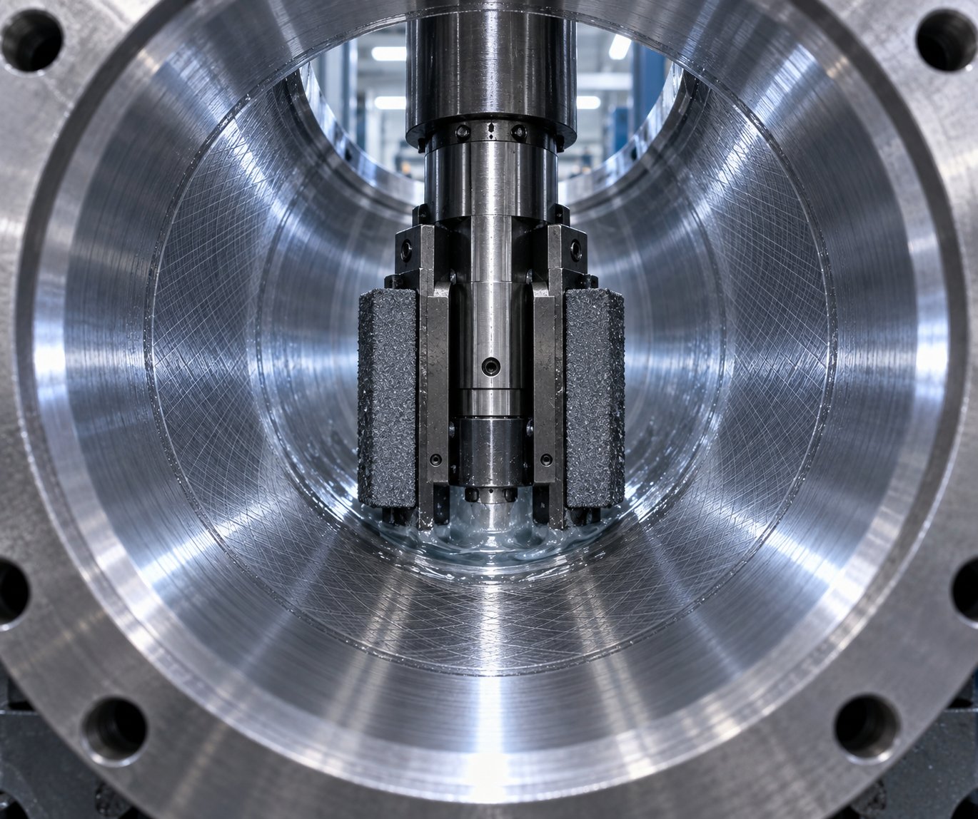
Bore honing is the lighter intervention. A honing machine uses rotating abrasive stones inside the bore to restore surface finish, correct minor ovality, and re-establish the crosshatch pattern that retains a thin polymer melt film during operation. As Nan Yun Industrial's refurbishment guide details, a horizontal boring machine first corrects inner diameter ovality — restoring true roundness and straightness — before a vertical honing machine grinds the bore to the required size. Honing removes only a small amount of material, typically enough to clean up surface imperfections without significantly enlarging the bore. It works best when wear is relatively uniform and shallow, and when the barrel's protective layer — whether nitrided case or bimetallic liner — still has usable thickness remaining.
Here is the counter-intuitive part: on a bimetallic barrel with a typical 1.5 mm alloy liner, uniform wear barely touches the liner budget. By the time clearance reaches the replacement threshold — roughly twice the as-new value — the liner may have surrendered only about 3 to 6 percent of its total thickness. Add a cleanup honing pass, and you have consumed perhaps another 3 to 7 percent. That means three, four, or even five hone-and-oversize-screw cycles are possible before the liner is anywhere close to exhausted — provided wear is even and no deep localized damage exists.
Re-boring steps in when wear has progressed beyond what honing alone can correct. The process machines the bore to a larger standard diameter — typically in increments of 1 to 2 mm — and the barrel is then paired with a matched oversized screw. This extruder barrel bore honing and re-boring repair approach effectively gives you a dimensionally refreshed plasticating unit. Re-boring is also the appropriate response when the bore has developed significant ovality from uneven wear or when localized scoring has created grooves too deep for a honing pass to reach without removing excessive material everywhere else.
The critical decision point between honing and re-boring turns on the worst single point in the bore, not the average measurement. A barrel that reads close to nominal along most of its length but has one deep score or gouge will force a cleanup pass deep enough to chase that worst spot — potentially pushing the bore beyond the honing range and into re-boring territory.
Bimetallic Liner Replacement and Barrel Straightening
What happens when the liner itself is compromised — worn through to the backing steel by localized abrasive attack, eaten away by corrosive pitting from PVC or fluoropolymer byproducts, or gouged by a foreign object that passed through the feed throat? Honing or re-boring cannot help if the hard, wear-resistant layer is simply gone.
The bimetallic barrel liner replacement process involves removing the depleted liner and centrifugally casting a new alloy layer inside the existing steel backing tube. The replacement liner can be iron-based, nickel-based, or tungsten-carbide-bearing, selected to match the polymer being processed — just as you would choose the appropriate alloy for a screw rebuild. Windsor Feedscrews notes that re-sleeving can cover just the worn stroke section or the full barrel length, using standard bimetallic, carbide, or corrosion-resistant liner materials depending on the application's demands. After casting, the new liner is machined and honed to final bore tolerances, restoring the barrel to full service life — often at 40 to 60 percent of new-barrel cost.
Not every barrel backing is a good candidate for re-lining, though. The steel tube must be straight, structurally sound, and free of cracks or significant external corrosion. If the backing itself has been weakened by years of thermal cycling or mechanical stress, investing in a new liner inside a compromised shell is money poorly spent.
That brings up a related issue: barrel straightening. Barrels are long, heavy cylinders subjected to repeated heating and cooling cycles, sometimes reaching 400 degrees Celsius and above for engineering plastics. Over time, improper support — sagging cradles, missing barrel supports, or uneven mounting — allows the barrel to develop a bow. Even a few thousandths of an inch of deflection over the barrel length creates uneven screw-to-bore clearances that accelerate one-sided wear and cause the screw to ride against the barrel wall.
Straightening involves carefully applying controlled force — typically hydraulic — while monitoring deflection with precision indicators along the barrel's length. The process must be done gradually and at controlled temperatures to avoid introducing residual stresses that could cause the barrel to spring back or crack. Barrel straightening for thermal cycling damage is a specialized procedure, but it can save a barrel that would otherwise need full replacement simply because it no longer runs true.
Feed Zone and Barrel End-Cap Repairs
The feed zone — the section from the hopper opening through the first several diameters of the barrel — operates under conditions entirely different from the heated transition and metering zones downstream. Temperatures are deliberately kept cool to prevent premature melting and bridging. Many extruder barrels feature grooved feed sections with longitudinal or helical grooves machined into the bore to improve solids conveying by increasing the friction between pellets and the barrel wall. Cooling channels circulate water through this section to maintain the low temperatures that keep the grooves effective.
These design features create unique repair challenges. Groove profiles must be restored to their original geometry — depth, width, and pitch — because even small deviations alter conveying performance and throughput stability. Experienced repair shops offer groove repair on both the barrel bore and the feed housing section, along with water jacket reline and repair for rubber and specialty processing barrels. If the cooling channels themselves are corroded or blocked, they must be flushed, pressure-tested, and relined or replaced to ensure adequate thermal management. A feed section that cannot hold its target temperature undermines the entire extrusion process regardless of what happens downstream.
End-cap damage is another barrel repair scenario that rarely gets discussed but occurs more often than many operators realize. The discharge end of the barrel — where the breaker plate, screen pack, and die adapter mount — absorbs the full force of melt pressure generated by the screw. Back-pressure events from clogged screen packs, blocked die channels, or sudden viscosity spikes can stress this area beyond its design limits. The result can be cracked flanges, deformed sealing surfaces, or bolt-hole elongation that prevents a proper seal.
Assessing end-cap damage starts with a visual inspection for cracks, followed by dimensional checks on the flange face flatness and bolt-hole concentricity. Minor deformation can often be machined flat and re-drilled. More severe damage — cracking that extends into the barrel wall, for instance — may require weld repair followed by stress relief heat treatment, or in some cases, removal and replacement of the end section entirely.
To pull all of these barrel-specific repair options into a quick-reference format, here they are organized by damage location:
- Feed zone: Grooved liner repair or replacement, cooling channel flushing and pressure testing, water jacket reline, bore honing to restore surface finish in the solids conveying section.
- Transition zone: Bore honing for moderate wear, re-boring paired with an oversized screw for heavier wear, bimetallic liner replacement if the alloy layer has been penetrated by corrosion or abrasion.
- Metering zone: Bore honing or re-boring (this zone typically sees the most wear due to highest melt pressures and temperatures), liner replacement for severe corrosive or abrasive damage, thermal spray coating for surface restoration.
- End cap / discharge flange: Flange face re-machining, bolt-hole repair or re-drilling, weld repair of cracks with post-weld stress relief, sealing surface restoration.
A barrel that has been honed, re-lined, straightened, or had its feed zone and end cap restored is only half the equation if the rebuilt geometry does not match the screw it will house. The dimensional relationship between screw and barrel — compression ratio, flight clearance, channel depth — is engineered for specific performance targets, and preserving or deliberately modifying those relationships during repair is the difference between a component that runs well and one that merely fits.
Preserving Screw and Barrel Geometry During Repair
A repaired screw can look flawless — fresh hard facing, pristine OD grind, mirror-finish flights — and still wreck your process if the rebuild altered the geometry that governs how polymer melts, mixes, and pressurizes. Every screw is an engineered system of interlocking dimensions, and each one affects plasticating behavior. Ignoring geometry during repair is like rebuilding an engine with the wrong compression ratio: it bolts in fine, but it never runs right.
Critical Dimensions That Must Be Maintained
The dimensions that matter most are the ones that control how polymer behaves as it moves from hopper to die. Consider these core parameters:
- Compression ratio: This is the ratio of feed channel depth to metering channel depth. It dictates how aggressively the screw compresses and melts the polymer. A screw designed with a 3:1 compression ratio for LDPE will underperform dramatically if a rebuild inadvertently shifts it to 2.5:1 — not enough compression means incomplete melting, while too much creates excessive shear heating and degradation. Screw compression ratio preservation during repair is not optional; it is fundamental to maintaining the melt quality the downstream process depends on.
- Flight pitch: The distance between successive flights determines conveying rate per revolution. As NC State Extension's extrusion research explains, increasing pitch increases shear input, while decreasing pitch reduces conveying capacity and compresses material more aggressively. A repair shop that grinds flight sides unevenly or allows weld buildup to encroach on the flight spacing effectively changes the pitch — and changes the process.
- Flight width (land width): The flat surface at the top of each flight controls the shear rate the polymer experiences as it passes between flight tip and barrel wall. Wider lands increase shear; narrower lands reduce it. During a weld rebuild and OD grind, the final land width must match the original specification, or the melt temperature profile shifts in ways that are difficult to troubleshoot from the operator console.
- Channel depth: Feed, transition, and metering sections each have specific channel depths that were calculated for the target polymer's melt behavior. Research from NC State confirms the progression: channel depth decreases from conveying to compression to metering zones, with each step designed to match the polymer's changing state from solid pellet to pressurized melt. Weld buildup on the screw root — or excessive material removal during root cleanup — alters these depths and changes compression behavior zone by zone.
- L/D ratio: The overall length-to-diameter ratio of the screw is fixed by the barrel length and cannot change during repair. However, maintaining L/D ratio during a screw barrel rebuild means ensuring that the effective functional zones — feed, transition, and metering — retain their designed proportions. A rebuild that shortens the effective transition zone by leaving weld-buildup geometry slightly off-spec can shift where melting occurs, creating unmelted pellets or excessive discharge temperatures.
- Barrel bore diameter: When a barrel is re-bored to a larger diameter, every clearance in the system changes. The re-bored barrel absolutely requires a matched oversized screw with flights ground to the new bore dimension. Installing the original screw — or a screw built to the old bore spec — in a re-bored barrel creates excessive clearance that defeats the purpose of the barrel repair entirely.
The practical implication is clear: extruder screw geometry dimensional measurement must happen before any repair work begins, not after. Davis-Standard's feedscrew maintenance protocol lays out the baseline measurement process — pull the screw, clean it thoroughly with brass tools and copper gauze (never steel wire brushes that damage the surface), let it cool to room temperature, then use an OD bar micrometer to measure the outside diameter of every flight along the screw's length. Number the flights, photograph each section with a tape measure for reference, and plot the measurements against original specifications in a spreadsheet. That visual comparison instantly reveals where wear has concentrated and by how much each zone has deviated from design intent.
Barrel measurements follow the same logic. Bore gauge readings taken at regular intervals along the barrel length, recorded at multiple clock positions (12, 3, 6, and 9 o'clock), reveal both overall enlargement and ovality. Together, the screw and barrel datasets give the repair shop — and you — the complete dimensional baseline needed to plan a rebuild that restores the original geometry rather than approximating it.
Opportunities to Optimize Geometry During Repair
Here is where repair gets interesting. A straight restoration to original specs makes sense when you are processing the same resin the screw was designed for. But what if your operation has changed? Maybe you switched from unfilled polypropylene to a 30% glass-filled nylon three years after buying the machine. Or you added a color concentrate that demands better distributive mixing than the original metering section provides. Repair presents a potential window to modify screw geometry — optimizing screw design during the repair process rather than simply copying what was there before.
Possible modifications include:
- Adjusting the compression ratio to better match a new resin's melt characteristics — a higher ratio for materials that need more aggressive solid-bed compaction, a lower ratio for shear-sensitive polymers like PVC.
- Adding mixing elements — such as a Maddock mixer or pineapple-style dispersive section — to improve color dispersion or additive distribution in the metering zone.
- Modifying channel depth in the metering section to change residence time and shear history for polymers that degrade at extended exposure or need more energy input to fully homogenize.
- Changing barrier flight configurations on barrier screws to improve melt-film management for polymers with different viscosity profiles than the original design target.
Repair should restore the original design intent unless a deliberate, engineering-driven decision is made to optimize for changed processing conditions. Geometry changes made without understanding their downstream effects on melt temperature, pressure, and mixing quality will create new problems faster than they solve old ones.
The caution here is real. Screw geometry modifications require process engineering knowledge — an understanding of how compression ratio, flight pitch, and channel depth interact with the specific polymer's viscosity curve, melting behavior, and thermal sensitivity. A repair shop that offers to "upgrade" your screw geometry without asking detailed questions about your resin, throughput targets, and downstream equipment is a red flag, not an asset. The best outcomes happen when the operator's process engineering team collaborates directly with the rebuild shop, using the pre-repair dimensional data as the starting point for any design discussions.
Whether the goal is faithful restoration or deliberate optimization, the quality of the outcome hinges on what happens after the rebuilt component goes back into the machine — and that leads directly to the question every maintenance engineer and plant manager faces before committing to a repair: is the damage repairable in the first place, or has the component crossed the line where replacement becomes the smarter investment?
Repair or Replace Worn Extruder Components: A Decision Framework
You have dimensional data in hand, you know which wear mechanism caused the damage, and you understand which repair techniques could restore the component. The next question is deceptively simple: should you repair it at all? Making this call incorrectly — rebuilding a screw that should have been replaced, or scrapping a barrel that had plenty of rebuildable life left — is one of the most expensive mistakes in extrusion maintenance. An extruder screw repair vs replacement cost comparison is not just about the price tag on the invoice. It is about expected service life, production risk, lead time, and whether the repaired component can actually deliver the performance your process demands.
Technical Factors That Favor Repair
Repair makes strong technical sense when the damage is surface-level and the core of the component remains structurally sound. Here are the scenarios where repair is typically the right call:
- Uniform abrasive wear within rebuildable limits: Flight tips that have thinned evenly from processing filled resins are ideal candidates for weld buildup and OD grinding. The base metal beneath the wear zone retains its original properties — no cracks, no metallurgical compromise. A PTA or alloy spray rebuild restores the working surface while preserving the stress history and grain structure of the original screw.
- Corrosion damage confined to the surface layer: Pitting from PVC or fluoropolymer byproducts that has not penetrated deeply into the base metal can be machined away and re-coated with a corrosion-resistant alloy overlay. The key qualifier is depth — surface-level corrosion that affected only the nitrided case or the outermost portion of a bimetallic liner is very different from corrosion that has eaten into the structural steel beneath.
- Flight tip wear addressable through weld buildup: Worn hard facing that has not yet exposed the softer substrate to accelerated erosion can be stripped, re-welded, and ground back to spec — often with an upgraded alloy that outperforms the original. As Nan Yun Industrial's refurbishment data shows, PTA welding on the thread crest after a base repair can more than double the screw's service life compared to a nitrided screw prior to refurbishment.
- Barrel bore wear within honing or re-boring range: A barrel that has enlarged uniformly but still has substantial liner thickness remaining is a strong repair candidate. Multiple hone-and-oversize-screw cycles are often possible before the liner budget is exhausted, as discussed in the barrel repair section above.
The common thread across these scenarios is that the damage is predictable, surface-confined, and correctable with established techniques that produce documented, measurable outcomes. The repaired component retains its original base metal integrity — the part you cannot rebuild — while getting a fresh working surface that can meet or exceed new-component specifications.
When Replacement Becomes the Better Investment
There is a clear line where repair stops making sense, and crossing it usually has nothing to do with cost alone. Replacement becomes the better investment when the damage compromises the structural integrity of the component in ways that repair cannot reliably reverse.
- Fatigue cracking at flight roots: As covered in the wear mechanism section, cyclic stress cracks propagate from inside the material outward. Welding over a fatigue crack buries the crack tip beneath new material without arresting its growth. If dye-penetrant or magnetic particle inspection reveals cracks at multiple flight roots — particularly in the compression zone — the screw's structural life is effectively over.
- Severely bent or bowed screws: A screw that has developed a noticeable bow from a blockage event, improper handling, or sustained one-sided thermal loading may not straighten reliably. Even if straightened, residual stresses in the base metal can cause it to re-bow under service conditions or create localized weak points prone to fatigue.
- Barrels worn beyond re-boring limits: Every barrel has a maximum bore diameter dictated by the remaining wall thickness needed for safe operation at working pressures. When wear pushes the bore past this limit — or when the bimetallic liner has been completely consumed — no amount of honing or re-boring can save it.
- Original metallurgy incompatible with current processing: Imagine inheriting a machine that was originally set up for unfilled polypropylene but now runs 40% glass-filled nylon. The screw's base metal may be a standard alloy steel without the toughness to accept the carbide-rich hard facing that glass-filled compounds demand. Rebuilding that screw with an aggressive overlay on incompatible substrate metal invites delamination. A new screw engineered from the ground up for the current resin is the smarter path.
- Extensive coating failure or deep pitting: When hard-facing alloy has delaminated across large sections, or when corrosion and pitting are severe enough that the repair shop must remove so much base metal that final dimensions fall outside acceptable tolerances, the economics flip decisively toward replacement.
A useful rule of thumb from experienced rebuilders: if the repair cost exceeds 60-70% of a new component's price and the expected post-repair service life is less than 70% of a new part's projected life, replacement usually delivers better long-term value.
Financial and Operational Decision Criteria
Technical feasibility determines whether repair can work. Financial and operational factors determine whether it should work for your specific situation. The screw barrel repair expected service life, the cost ratio, the production schedule impact, and even your spare-parts strategy all factor into the final decision.
Repair costs commonly fall between 30% and 50% of new-component pricing — a substantial saving, especially on large-diameter extruder screws or long barrels where new units carry five-figure price tags. Lead time differences can be equally dramatic: a professional rebuild may ship in one to two weeks, while a new bimetallic screw or barrel from an OEM can take eight to sixteen weeks depending on size, metallurgy, and the manufacturer's backlog.
For operations running multiple extrusion or injection molding lines, the strategic value of keeping spare screws and barrels in inventory cannot be overstated. Industry research consistently shows that unplanned downtime — the kind that occurs when a worn component fails catastrophically and no replacement is on the shelf — costs manufacturers disproportionately more than the component itself, once lost throughput, idle labor, missed deliveries, and emergency expediting fees are factored in. Repair turnarounds measured in days rather than months make it economically viable to rebuild a worn component as a ready spare while the current set is still running — a rotational strategy that virtually eliminates emergency downtime from screw or barrel failure.
The following table consolidates the key decision criteria into a scannable framework you can reference when evaluating your own repair-or-replace situation:
| Decision Criterion | Favors Repair | Favors Replacement |
|---|---|---|
| Damage Severity | Surface-level wear; uniform abrasion; shallow corrosion; flight tips worn but base metal intact | Fatigue cracking at flight roots; deep pitting into base metal; bent or bowed screw; liner completely consumed |
| Cost Ratio (Repair vs. New) | Repair cost is 30-50% of new component price | Repair cost exceeds 60-70% of new component price with lower expected life |
| Lead Time | Rebuild turnaround of 1-2 weeks meets production schedule; downtime window is short | Production schedule allows 8-16 week lead time for new component; or repair turnaround offers no meaningful advantage |
| Expected Post-Repair Service Life | Rebuilt component projected to deliver 70-100%+ of new-component life (especially with upgraded alloys) | Damage extent limits post-repair life to less than 50% of a new component; frequent re-repairs anticipated |
| Geometry Requirements | Original geometry can be faithfully restored; or minor optimization is desired and engineered | Original screw design is fundamentally wrong for current resin; complete re-engineering of flight geometry needed |
| Metallurgical Compatibility | Base metal accepts required repair alloy; original construction supports the rebuild technique | Base metal cannot accept the hard-facing or overlay needed for current processing conditions |
| Component History | First or second repair cycle; documented maintenance records available | Third or subsequent repair (base metal degradation risk); no records of prior repairs or operating conditions |
Beyond the table, a few logistical realities shape the decision in practice. When coordinating downtime for the repair, communicate clearly with your service provider about three things upfront: the polymer you process (so they select the correct alloy), the dimensional data from your pre-repair measurements (so they know the starting point), and your expected delivery date (so they can schedule the work without surprises). Experienced providers will ask for this information proactively — and shops that do not ask should prompt a second thought about whether they understand the scope of the job.
Expected turnaround times for a typical screw rebuild — weld, grind, surface treat — run five to ten business days for most providers, though rush services are available at a premium. Barrel honing may take two to five days; full liner replacement adds one to three weeks depending on alloy availability and barrel length. Planning a repair during a scheduled shutdown — rather than reacting to a catastrophic failure mid-production — compresses the impact on your operation to near zero, especially if you have a spare set rotating through the cycle.
The repair-or-replace decision is ultimately a risk management exercise. Repair manages cost and lead-time risk when the component's structural core is sound. Replacement manages performance and reliability risk when the damage runs too deep for any surface restoration to deliver a lasting result. Making that call confidently, though, depends on one more critical step: verifying that the repaired component actually meets specification before it goes back into service — and knowing how to evaluate the shop that performed the work.
Post-Repair Quality Verification and Choosing a Repair Service Partner
A rebuilt screw arrives at your dock looking pristine — fresh hard facing gleaming under the shop lights, flights ground smooth, every surface polished. It is tempting to bolt it straight into the machine and get back to production. That temptation is exactly how operators end up paying twice. Without a structured acceptance protocol that confirms the rebuild actually meets specification, you are trusting appearance over measurement — and appearance has never kept a clearance within tolerance or guaranteed a weld bond will hold at operating temperature.
Post-repair quality verification is the final safeguard between a successful rebuild and a premature failure. It is also the step most often skipped or abbreviated under schedule pressure. The procedures below turn that safeguard into a repeatable system.
Dimensional Verification and Hardness Testing
The same pre-repair dimensional baseline you collected before sending the component out is now your acceptance standard. Every critical measurement taken before the repair should be repeated on the returned component — and the results should match or exceed the original design specifications, not just look better than the worn-out values.
For screws, the essential post-repair dimensional inspection includes:
- Flight OD at multiple points: Use an OD bar micrometer spanning two flights to measure the outside diameter at intervals along the full screw length. Adams Engineers recommends using a parallel test bar across the flights for consistent, repeatable readings. Compare each measurement to the target bore clearance — typically 0.001 in. per side per inch of nominal diameter. Any point that falls outside tolerance flags a grinding issue the shop needs to correct before installation.
- Root diameter (channel depth): Verify that the root diameter in each zone — feed, transition, and metering — matches the original or agreed-upon modified design. Weld buildup on the root or excessive cleanup grinding can shift compression ratio without anyone noticing until the process runs poorly.
- Flight width (land width): Measure the flat surface at the top of each flight. Post-weld OD grinding can narrow or widen flight lands depending on how the grinder was set up. Deviations alter the shear rate the polymer experiences in the flight-to-bore gap.
- Straightness check: Roll the screw on a granite surface table — or the cleanest flat surface available — and check for daylight between the flights and the table surface. Feeler gauges quantify any bow. A screw that was straight before repair should be straight after. Welding heat can introduce distortion that must be corrected before the component ships.
For barrels, post-repair verification focuses on bore geometry:
- Bore diameter at intervals: Use a bore gauge to measure at multiple positions along the barrel length and at several clock positions (12, 3, 6, and 9 o'clock) at each station. This reveals both overall diameter accuracy and any residual ovality the honing or re-boring process should have eliminated.
- Surface finish measurement: The barrel bore should exhibit the characteristic crosshatch honing pattern that retains a thin polymer melt film during operation. Surface roughness readings — typically specified in Ra (roughness average) — confirm the honing quality. Too rough increases friction and wear; too smooth reduces melt adhesion and conveying efficiency.
Hardness testing on rebuilt areas provides direct evidence that the weld overlay or coating was applied correctly and will perform under service conditions. Rockwell C (HRC) testing is standard for weld overlays and hard-facing deposits, while Vickers (HV) testing works better for thinner coatings like HVOF or HVAF thermal sprays where the indentation needs to stay within the coating layer. Request hardness readings at several locations along the rebuilt zone — not just one spot — because uneven alloy distribution or inconsistent heat input during welding can produce soft spots that wear preferentially in service. Typical targets vary by alloy: carbide-rich PTA overlays commonly reach 55-62 HRC, while nickel-based corrosion-resistant alloys run 40-50 HRC. The repair shop should provide a written hardness report as part of their delivery documentation.
Run-Off Procedures and Performance Validation
Dimensional checks confirm the component was built correctly on the bench. Performance validation confirms it actually works in your machine, with your resin, under your operating conditions. These are two different things — and skipping the second one leaves you flying blind until a quality issue surfaces in production.
Reinstalling the repaired screw or barrel calls for a controlled start-up sequence, not a rush to full rate. Treat the first run after a rebuild the same way you would commission a brand-new component:
- Inspect the mating component: If you rebuilt the screw, measure the barrel bore before reinstallation to confirm the clearance relationship is correct. Installing a rebuilt screw into a worn barrel — or vice versa — negates the repair investment. Both halves of the plasticating system must be within specification simultaneously.
- Follow standard start-up procedures: Heat the barrel to operating temperature per your resin's profile, start the screw at low speed, and begin feeding material gradually. Wylong's pre-startup protocol for twin screw extruders emphasizes starting at 50-100 rpm and feeding material within 2-3 minutes of reaching operating temperature to avoid idle-heat degradation — advice equally applicable to single screw lines after a component swap.
- Monitor motor amperage: Record drive motor amps at steady state and compare to pre-repair baseline values. A properly rebuilt screw-and-barrel set should show stable or reduced amperage at the same screw speed and throughput rate, reflecting restored pumping efficiency and reduced drag from tight clearances.
- Track melt temperature stability: Use a handheld pyrometer or the machine's melt thermocouple to check discharge temperature consistency. Temperature swings that were present before the repair should be reduced or eliminated. Persistent instability after a rebuild suggests a geometry issue — possibly a compression ratio deviation or a clearance mismatch — worth investigating before running full production.
- Measure throughput: Weigh output over a timed interval at your standard operating conditions. Compare to the machine's rated output and to your pre-repair production logs. Restored throughput — without compensating by increasing screw speed — is the clearest single indicator that the repair succeeded.
- Inspect product quality: Run samples through your standard QC checks — dimensional tolerance, surface finish, color uniformity, mechanical properties if applicable. Look specifically for the defects that triggered the repair decision in the first place: streaking, unmelted particles, black specks, or dimensional variation.
- Document everything: Record all run-off data — amperage, melt temperature, throughput, quality results — alongside the dimensional and hardness data from the bench inspection. This documentation becomes the new baseline for tracking wear over the component's next service cycle and for planning future repairs based on actual performance trends rather than calendar-based guesses.
That final point deserves emphasis. The most valuable outcome of a thorough post-repair validation is not confirming that today's rebuild is good — it is building the dataset that tells you when the next repair will be needed. Adams Engineers' maintenance guidance highlights this directly: recording measurements at standard intervals creates a wear profile that identifies the expected lifespan of a component, allowing for planned replacement and repair rather than reactive emergency shutdowns.
Choosing a Qualified Repair Service Partner
Every step outlined above — from pre-repair measurement through post-repair validation — depends on the competence of the shop performing the work. A repair provider who cuts corners on alloy selection, skips hardness testing, or returns a screw without a dimensional report is not saving you money. They are deferring the cost to your next unplanned shutdown.
Here is what to evaluate when selecting a service partner for plastic extruder screw barrel repair:
- Range of repair techniques offered: A shop limited to a single method — only manual hard facing, for example — will apply that method regardless of whether it is the best fit for your damage type. Look for providers who offer multiple weld-based options (alloy spray welding, PTA, MIG/TIG hard facing), surface treatments (nitriding, thermal spray), and finishing capabilities (OD grinding, barrel honing, re-boring). Breadth of capability indicates both equipment investment and technical depth.
- Experience with your specific polymer and machine type: A provider who regularly services screws running glass-filled nylon understands the alloy choices and wear patterns that application demands. Ask for references or case studies involving your resin family and extruder or injection molding machine size range. Generic experience is useful; application-specific experience is decisive.
- Support for both extrusion and injection molding: Many operations run both process types. A repair partner who understands the differences — continuous-duty wear patterns in extrusion versus cyclic loading and non-return-valve considerations in injection molding — can serve your entire fleet rather than just part of it.
- Turnaround time commitments: Get specific timelines in writing, including what happens if the shop discovers additional damage during disassembly or inspection. Reliable providers communicate proactively when scope changes rather than silently extending the schedule.
- Quality documentation provided: At minimum, expect a dimensional report (pre- and post-repair measurements), hardness test results on rebuilt surfaces, and a description of the repair techniques and alloys used. This documentation is not a nice-to-have — it is the evidence that the work was done correctly and the baseline for your next wear-tracking cycle.
- Material and alloy transparency: The shop should be able to tell you exactly which alloy they plan to deposit and why it matches your application. Vague descriptions like "hard facing" or "wear-resistant overlay" without specifying the alloy composition are a warning sign. As the polymer-specific repair discussion made clear, the wrong alloy for your resin is worse than no repair at all.
As a concrete example of how these criteria translate in practice, NANHAIYA is one provider that checks several of these boxes — they support both extrusion and injection molding operators with alloy spray welding and wear-resistant surface treatment options, addressing screw wear, barrel wear, corrosion, and service-life concerns across a range of applications. Evaluating a provider like NANHAIYA against the full criteria list above — asking about their experience with your specific resin, requesting sample documentation from prior jobs, and confirming turnaround commitments — is exactly the kind of due diligence that separates a repair investment from a repair gamble.
Ultimately, the quality of your repair partner shapes every outcome discussed in this article — from whether the right wear mechanism gets identified, to whether the correct alloy gets applied, to whether the finished component arrives with the dimensional accuracy and documentation you need to validate performance and track future wear. A qualified partner does not just fix your screw or barrel. They give you the data and confidence to manage your plasticating components as engineered assets rather than replaceable consumables — and that shift in perspective is what keeps you from paying twice.
Frequently Asked Questions About Plastic Extruder Screw Barrel Repair
1. How much does plastic extruder screw barrel repair cost compared to buying new components?
Professional screw and barrel repair typically costs between 30% and 50% of new-component pricing. The exact figure depends on the severity of damage, the repair technique required (alloy spray welding, PTA, re-boring, etc.), and the alloy specified. For large-diameter extruders, the savings can reach tens of thousands of dollars per set. Turnaround times are also significantly shorter — often one to two weeks for a rebuild versus eight to sixteen weeks for a new OEM build — which reduces costly production downtime.
2. What are the most common signs that an extruder screw and barrel need repair?
The earliest indicators usually appear in process data before visible damage is obvious. Watch for declining throughput at the same screw speed, rising motor amperage under unchanged conditions, inconsistent melt temperatures, poor color dispersion, and unmelted pellets in the extrudate. Mechanical symptoms include unusual vibrations and difficulty holding barrel zone setpoint temperatures. During scheduled shutdowns, pulling the screw may reveal scoring on flight lands, reduced flight height, barrel bore pitting, and cracking at high-stress transition zones. Catching these signs early keeps repair scope — and cost — manageable.
3. Which repair technique is best for extruder screws worn by glass-filled or mineral-filled resins?
Glass-fiber and mineral-filled compounds cause aggressive abrasive wear that demands the hardest available surface rebuilds. Plasma Transfer Arc (PTA) welding and alloy spray welding with high-tungsten-carbide overlays are the most effective methods, delivering metallurgically bonded layers 1-3 mm thick that can extend service life by three to five times compared to standard nitrided screws. Providers like NANHAIYA offer alloy spray welding tailored for these demanding applications, selecting carbide-rich alloys matched to the specific filler type and concentration being processed.
4. Can a repaired extruder screw or barrel last as long as a brand-new component?
Yes — and in many cases, longer. When the original component was built with standard nitrided steel, a professional rebuild using upgraded alloy overlays (such as PTA or alloy spray welding with carbide-rich compositions) can significantly exceed the original service life. Published data shows PTA-repaired screws achieving three to five times the lifespan of new nitrided screws in the same application. The key is matching the repair alloy to the dominant wear mechanism — abrasive, corrosive, or combined — rather than applying a generic hard-facing overlay.
5. How do I choose a qualified screw and barrel repair service provider?
Evaluate five critical areas: range of repair techniques available (alloy spray welding, PTA, thermal spray, honing, re-boring), documented experience with your specific polymer family and machine type, support for both extrusion and injection molding applications, written turnaround commitments with proactive communication on scope changes, and quality documentation including pre- and post-repair dimensional reports plus hardness test results. Ask for the exact alloy composition planned for your rebuild and why it suits your resin. Any shop that cannot answer that question specifically should raise a red flag.
Written by
Nanhaiya Technical Team
Zhoushan Nanhaiya Plastic Machinery Co., Ltd.
The Nanhaiya technical team supports screw and barrel manufacturing projects through application review, technical communication, custom manufacturing coordination, and production and quality control.
Discuss Your Application
Related Articles
More insights on screw barrel technology and plastics processing.

What Nobody Tells You About Screw Barrel For Plastic Machine Design
Oct 10, 2026
Learn how screw barrel for plastic machine design affects melt quality, throughput, and wear life. Covers geometry, resin matching, troubleshooting, and sourcing.
Read Article
Single Screw Extruder for Sheet: Stop Guessing, Start Specifying
Oct 9, 2026
Learn how to specify a single screw extruder for sheet production. Covers screw geometry, resin-specific processing, troubleshooting, and maintenance best practices.
Read Article
PE Pipe Extruder Machine: What Datasheets Won't Tell You
Oct 9, 2026
Learn how a PE pipe extruder machine works, key specs explained, material grade selection, maintenance tips, and buyer guidance beyond the datasheet.
Read ArticleLooking for something else?
Search by material, symptom or product and jump straight to the relevant page.
These are navigation suggestions based on keyword matching — not a quotation, not a delivery commitment, and not a substitute for engineering review. Final specification is confirmed by our engineers against your drawings and processed material.
Need help with screw barrel selection?
Share your machine model, processed material and application. Our team can help with pricing and technical support.