

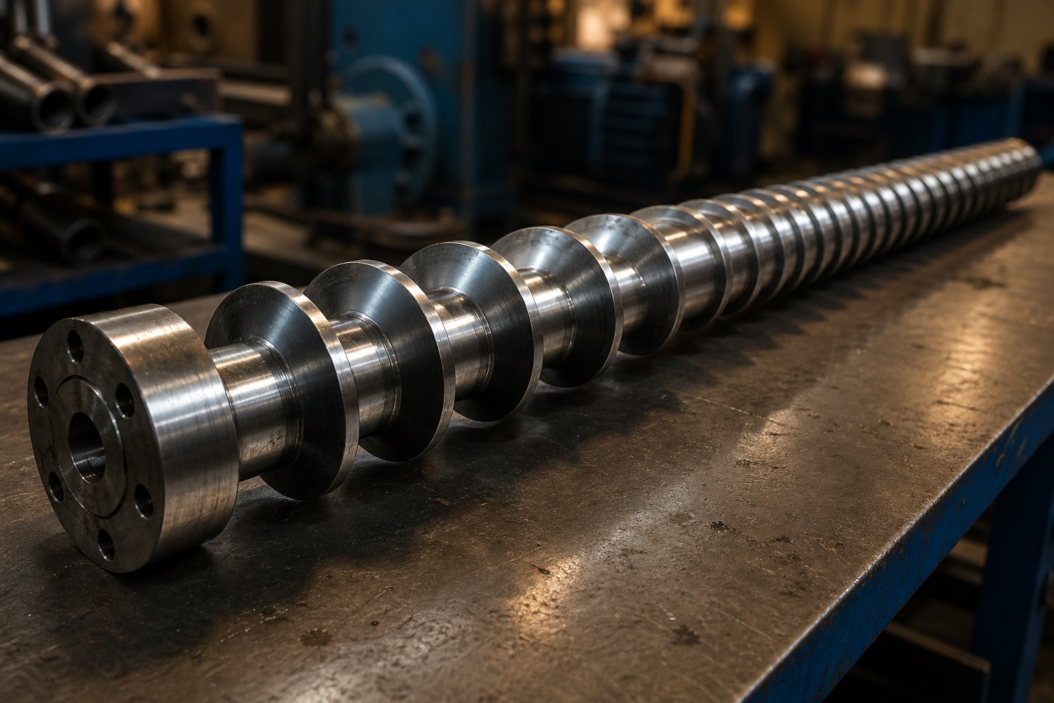
What a Plastic Extruder Screw Does and Why It Matters
Imagine a single component responsible for grabbing cold, solid pellets at one end and delivering a perfectly uniform molten stream at the other. That component is the plastic extruder screw, and it sits at the absolute center of every extrusion operation. Get its design right, and you unlock higher throughput, tighter tolerances, and lower energy bills. Get it wrong, and you're fighting scrap rates, inconsistent melt quality, and premature equipment failure.
What Is a Plastic Extruder Screw
An extruder screw is a precision-machined helical shaft that rotates inside a heated barrel. Its spiral flights create channels that perform four essential functions in sequence: conveying raw polymer from the feed throat, compressing the material to expel trapped air, melting it through a combination of shear energy and conducted heat, and metering a homogeneous melt at consistent pressure toward the die.
A plastic extruder screw is a rotating helical shaft housed within a cylindrical barrel that conveys, compresses, melts, and meters polymer material to produce a uniform, pressurized melt for downstream shaping.
Every geometric detail of this component — from channel depth to flight pitch — directly influences how efficiently those four functions happen. As NC State Extension research emphasizes, no gold standard exists for screw design because every polymer exhibits unique flow properties influenced by temperature, shear rate, and extruder geometry. That reality makes understanding the plastic extrusion screw a non-negotiable skill for anyone involved in processing or maintenance.
Why Screw Design Matters for Output Quality
Screw geometry isn't just an engineering detail — it's a business decision with measurable financial consequences. The relationship between an extruder screw and your bottom line is direct: flight depth and compression ratio control melt temperature uniformity, pitch and helix angle determine throughput capacity, and flight-to-barrel clearance governs pressure stability and energy consumption.
When a processor selects the wrong screw configuration — say, a high-compression design for a heat-sensitive resin like PVC — the results are predictable and costly. Excessive shear generates localized overheating, which degrades the polymer. The outcome? Increased scrap, wasted energy from reprocessing, and accelerated wear that shortens both screw and barrel life. One real-world case involved a processor who insisted on a 33:1 L/D ratio for rigid PVC, assuming longer meant better plasticization, only to find the prolonged residence time caused material degradation and burning.
This article is built as an engineering reference that goes well beyond surface-level descriptions. You'll find detailed breakdowns of screw geometry parameters, zone-by-zone functional analysis, structured comparisons of screw types, material-to-screw pairing guidance, metallurgy and coating selection frameworks, and practical maintenance protocols — everything a processor or maintenance team needs to make confident, data-driven screw decisions. The details that separate a well-optimized extrusion line from a problematic one often come down to geometry, and that's exactly where we begin.
Critical Screw Geometry Parameters That Control Performance
Screw design lives and dies in the numbers. Every millimeter of channel depth, every degree of helix angle, and every ratio between length and diameter shapes how polymer behaves inside the extruder barrel. Understanding these parameters individually is useful — but understanding how they interact is what separates optimized extrusion screw configurations from ones that waste energy and produce inconsistent melt.
L/D Ratio and Compression Ratio Explained
The length-to-diameter ratio (L/D) describes how long the screw is relative to its bore size. A screw with a 24:1 L/D — the most common ratio in single-screw extrusion — means the flighted length equals 24 times the nominal diameter. Some processors run 30:1 or longer for demanding applications, while a few shorter designs sit at 20:1.
Why does this matter? More length gives the polymer more residence time inside the barrel, which translates to greater melting efficiency, more thorough mixing, and increased energy input from shear. If heating, melting, or mixing are limiting your output, a longer L/D may solve the problem — but it also means more time at elevated temperatures, which can degrade heat-sensitive resins. Think of it as a trade-off: longer screws do more work, but they demand careful thermal management.
Compression ratio, on the other hand, describes how aggressively the screw densifies polymer from loose pellets into homogeneous melt. It's defined as the ratio of the channel volume in the first flight to the volume in the last flight — typically approximated by comparing feed zone depth to metering zone depth on a constant-pitch screw. Most general-purpose designs fall between 2:1 and 4:1. A higher compression ratio generates more pressure and shear, which suits semi-crystalline polymers that resist melting. A lower ratio is gentler — ideal for heat-sensitive materials like PVC that degrade under excessive mechanical work.
One critical nuance: compression ratio alone cannot fully describe a screw unless at least one actual channel depth is known. Two screws can share identical compression ratios yet behave very differently if their absolute channel depths differ. Always specify both ratio and depth when evaluating screw extrusion performance.
Flight Depth, Pitch, and Helix Angle
Channel depth is where shear rate and throughput capacity get determined. In the feed zone, flights are cut deep — deep enough to accept the bulk density of incoming pellets and convey them forward efficiently. In the metering zone, that depth shrinks dramatically, creating a shallow channel that generates high shear and delivers uniform melt at stable pressure. The depth difference between these two zones is, in fact, what defines your compression ratio.
Pitch refers to the axial distance from one flight to the next. Most extrusion screws use square pitch, meaning that distance equals the screw diameter. This convention makes it easy to estimate L/D simply by counting turns. Flight width — the thickness of the flight land itself — typically runs around 10% of barrel diameter. Wider flights waste usable screw length and generate excessive heat in the flight-to-barrel clearance zone, while narrower flights risk too much leakage flow past the flight land.
Helix angle follows directly from pitch. On a standard square-pitch screw, the helix angle is approximately 17.66 degrees. This angle influences solids conveying efficiency and the rate at which the melt pool develops along the channel. Adjusting helix angle changes how quickly material advances per revolution — steeper angles push material faster but reduce the shear work per unit length.
Flight clearance — the gap between the outer edge of the flight land and the extruder barrel wall — is one of the most wear-sensitive dimensions on the entire screw. On new screws, this clearance typically ranges from 0.005 to 0.010 inches (0.125 to 0.25 mm), with smaller screws running tighter and larger machines allowing slightly more. A tighter fit improves sealing and reduces leakage flow backward over the flights, but it also accelerates wear and generates more frictional heat in that narrow gap.
| Parameter | Definition | Effect on Process | Typical Range |
|---|---|---|---|
| L/D Ratio | Flighted screw length divided by nominal bore diameter | Controls residence time, melting efficiency, and mixing quality | 20:1 to 30:1 (24:1 most common) |
| Compression Ratio | Feed zone channel volume divided by metering zone channel volume | Determines pressure generation and shear intensity during melt transition | 2:1 to 4:1 |
| Flight Depth (Feed) | Radial distance from screw root to flight tip in feed zone | Sets solids intake capacity and initial conveying rate | Varies by diameter; deeper for low-bulk-density materials |
| Flight Depth (Metering) | Radial distance from screw root to flight tip in metering zone | Controls shear rate, melt homogeneity, and pumping efficiency | Typically 1/2 to 1/4 of feed depth |
| Pitch | Axial distance between adjacent flights | Influences forward conveying rate per revolution | Usually equal to screw diameter (square pitch) |
| Helix Angle | Angle of flight relative to a plane perpendicular to screw axis | Affects solids conveying efficiency and shear distribution | ~17.66° for square pitch |
| Flight Width | Axial thickness of the flight land | Balances sealing against leakage flow and heat generation | ~10% of barrel diameter |
| Flight Clearance | Radial gap between flight land OD and barrel bore | Controls leakage flow, sealing efficiency, and wear rate | 0.005–0.010 in. (0.125–0.25 mm) |
Here's where screw design becomes genuinely complex: these parameters never act in isolation. Deepen the metering channel and you reduce shear — good for heat-sensitive resins — but residence time increases and pumping efficiency against back-pressure drops. Tighten flight clearance and you improve sealing, which boosts output consistency — but barrel and flight wear accelerates, especially when processing filled compounds. Increase L/D and you gain mixing length, yet you also extend thermal exposure and raise capital cost.
Every geometry decision triggers a cascade of secondary effects. That interconnectedness is precisely why matching screw parameters to specific polymer behavior — rather than relying on a one-size-fits-all configuration — makes the difference between a process that runs smoothly and one that constantly demands operator intervention. The next layer of that match lies in understanding what physically happens to the polymer as it moves through each functional zone of the screw.
Feed, Compression, and Metering Zones in Engineering Depth
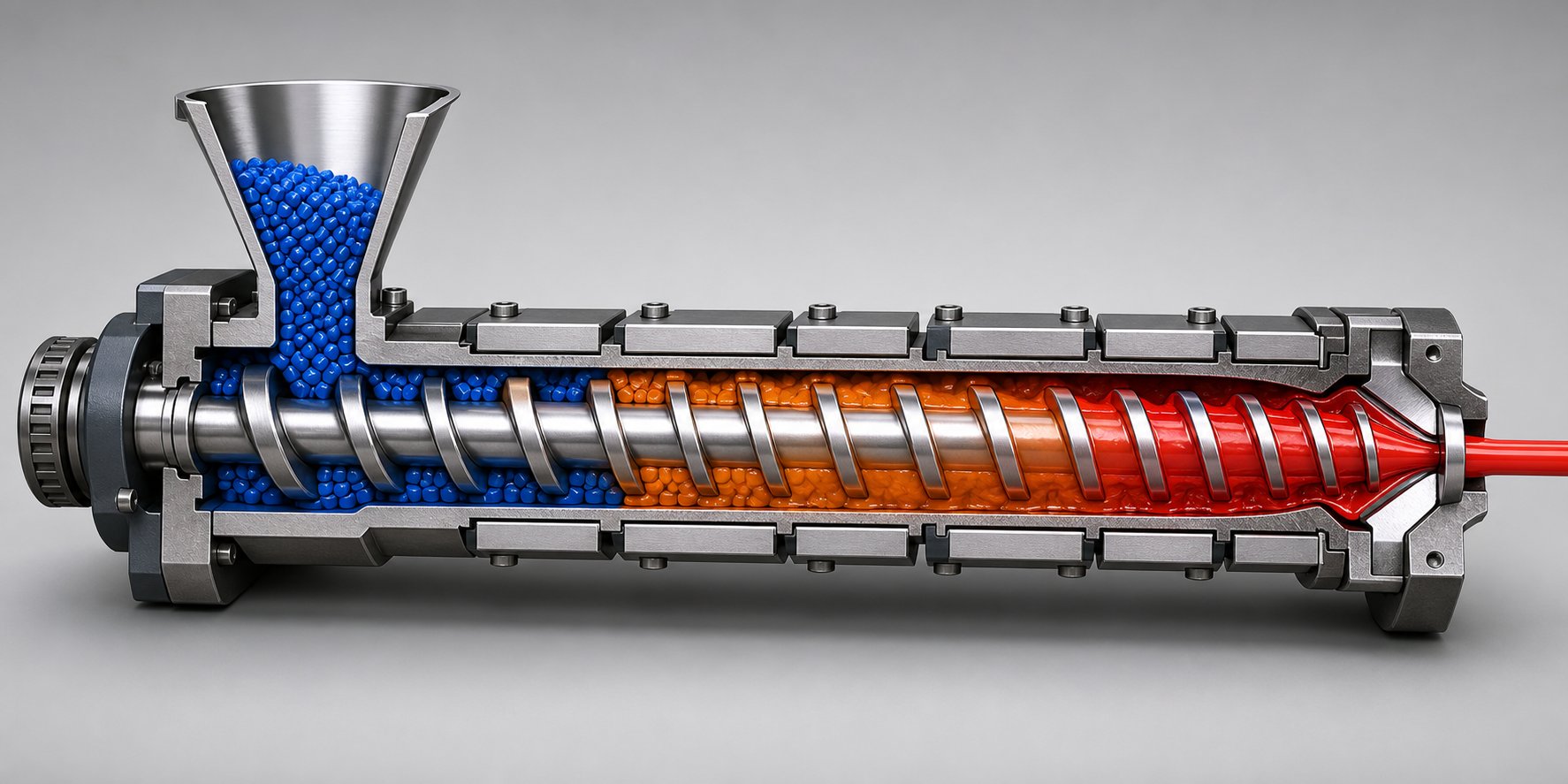
A plastic extruder screw doesn't apply the same mechanical action uniformly from hopper to die. Instead, it's divided into three distinct functional zones — each with a different channel geometry, a different physical mechanism, and a different job to accomplish. Understanding what actually happens to the polymer inside each zone is the key to diagnosing process problems, selecting the right screw barrel configuration, and optimizing output for any given resin.
Feed Zone Function and Design Considerations
The feed zone is where solid pellets or powder first enter the screw channel from the hopper. Its primary job sounds simple — grab the material and push it forward — but the physics behind solids conveying are anything but straightforward.
Pellets don't flow like liquid. They move forward only when friction between the polymer and the extrusion barrel wall exceeds friction between the polymer and the screw root. This friction differential is what drives conveying: the barrel needs to "grip" the pellets while the screw surface allows them to slide. That's why many extruder feed barrel sections are grooved or roughened on the barrel bore, and why screw surfaces in this zone are often polished smooth. If that friction balance tips the wrong way, pellets simply spin with the screw rather than advancing — and output plummets.
Flight depth in the feed zone must be generous enough to accommodate the bulk density of incoming material. Pellets contain significant interstitial air, so the channel volume here is always the largest on the entire screw. A deeper feed zone grabs more material per revolution, establishing the throughput baseline for everything downstream.
Feed zone length varies significantly by polymer type. Semi-crystalline resins like polyethylene and polypropylene have sharp, well-defined melting points, meaning they resist softening until a specific temperature threshold is reached. These materials need longer feed zones — sometimes up to 50% of total screw length — to build enough pressure and frictional heat before the compression zone can begin meaningful melting. Amorphous polymers such as polystyrene or ABS soften gradually over a broad temperature range, so shorter feed zones work effectively because the transition to melting starts earlier and more progressively.
Compression Zone and Melt Transition
This is where the real transformation happens. As the screw channel depth gradually decreases, the available volume shrinks — compressing the polymer bed, squeezing out trapped air (which vents back toward the feed throat), and generating intense shear heating that combines with conducted heat from the barrel walls to initiate melting.
Picture what's occurring at the microscopic level: a thin melt film forms where polymer contacts the hot barrel surface. The rotating screw scrapes this film off, collecting it into a growing melt pool on one side of the channel while the remaining solid bed compresses against the opposite side. This mechanism — known as the Tadmor melting model — continues progressively until the solid bed is consumed entirely.
The compression ratio, defined as feed depth divided by metering depth, governs how aggressively this compaction occurs. Typical values range from 2:1 to 4:1 depending on the polymer family. Polyolefins, with their high crystallinity and significant density change upon melting, generally require ratios in the 3:1 to 4:1 range. Heat-sensitive materials like PVC call for much gentler compression — often around 2:1 — to avoid degradation from excessive shear. Engineering resins like polycarbonate and nylon fall somewhere in between, typically around 2.5:1 to 3.5:1.
Compression zone length also matters. A gradual taper spread over many turns produces gentler melting with less thermal variation, while a short, aggressive compression zone generates rapid pressure buildup that suits high-output applications — but risks unmelted solids breaking through if the polymer can't absorb energy fast enough.
Metering Zone and Melt Homogeneity
By the time polymer reaches the metering zone, it should be fully molten. This final section features a constant, shallow channel depth designed to do one thing exceptionally well: deliver homogeneous melt at consistent pressure and temperature to the die.
The metering zone functions as a viscous drag pump. Melt is dragged forward by the rotating screw flights while back-pressure from the die and downstream tooling resists that flow. The balance between these two forces — drag flow forward, pressure flow backward — determines actual output rate. A well-designed metering zone maintains consistent pressure and temperature uniformity, which directly translates to dimensional stability in the final product.
Metering zone length relative to total screw length has a measurable impact on output stability. Too short, and pressure fluctuations from the compression zone propagate straight through to the die, causing surging. Too long, and excessive residence time at high temperature risks thermal degradation — particularly problematic for heat-sensitive resins.
Here's where polymer selection reshapes the entire screw barrel layout. Zone proportions shift substantially across resin families:
- Polyolefins (PE, PP): Typically use a longer feed zone (~50%), moderate compression zone (~25%), and moderate metering zone (~25%), reflecting their sharp melting point and high crystalline energy requirement.
- PVC: Demands a shorter feed zone (~25-30%), very gradual compression zone (~35-40%), and longer metering zone (~30-35%) to minimize shear heating and allow gentle, controlled fusion without degradation.
- Engineering plastics (PC, nylon, ABS): Often employ a moderate feed zone (~30-35%), moderate compression zone (~25-30%), and relatively longer metering zone (~35-40%) to ensure complete melting and thorough homogenization of these higher-viscosity melts.
- Fluoropolymers (PTFE, FEP): Require exceptionally low compression ratios and extended metering zones due to corrosive off-gassing and extreme sensitivity to shear-induced degradation.
These proportions aren't arbitrary guidelines — they reflect the fundamental thermodynamic and rheological behavior of each polymer family. A screw designed with polyolefin zone ratios will underperform catastrophically when loaded with rigid PVC, and vice versa. That direct link between polymer properties and zone geometry is exactly why screw type selection — from general-purpose to barrier to vented designs — demands careful alignment with the material being processed.
Screw Types Compared from Metering to Barrier to Vented
Zone geometry defines what happens to the polymer — but screw type defines what's even possible. A perfectly proportioned three-zone layout still has a ceiling on melting capacity, mixing intensity, and volatile removal. When your process hits that ceiling, the answer isn't tweaking barrel temperatures or adjusting RPM. It's choosing a different screw type altogether. Knowing which type matches your application is one of the most consequential decisions a processor can make, and it's one that many get wrong by defaulting to what they've always run.
General-Purpose, Barrier, and Mixing Screws
The general-purpose (GP) metering screw is the baseline — the workhorse of single extruder screw configurations worldwide. It uses one continuous helical flight across all three zones: feed, compression, and metering. Each zone typically occupies roughly one-third of the total flighted length. This design is economical, versatile, and straightforward to maintain, making it the default choice for processors running standard commodity resins like PE or PP in pipe, profile, or sheet applications.
Its limitation? A single-flight conventional screw has finite melting capacity and minimal mixing capability. When you push output rates higher or switch to harder-to-melt resins, unmelted particles — sometimes called "fisheyes" — start showing up in your product. No temperature adjustment fully compensates for that shortfall.
That's exactly the problem barrier screws were engineered to solve. A barrier screw introduces a secondary flight — the barrier flight — within the compression zone. This creates two separate channels: one that holds the solid bed and another that collects the growing melt pool. The clearance between the barrier flight and the barrel wall is intentionally narrow, allowing only fully melted polymer to pass over into the melt channel. The result is that essentially no unmelted polymer can reach the metering zone. You get more complete melting, better thermal homogeneity, and significantly more stable output — particularly valuable for film extrusion and thin-wall applications where even a single unmelted granule creates a defect.
Then there are mixing screws, which address an entirely different bottleneck: dispersion and distribution of additives, colorants, and fillers. These extruder screws incorporate specialized elements — usually positioned near the end of the metering zone — that force the melt through geometries designed to divide, recombine, and shear the material in controlled ways. The three most common mixing element types each serve a distinct purpose:
- Maddock (fluted) mixers: A dispersive design that forces melt over narrow shear dams, breaking up hard agglomerates like pigment clumps and gel particles. Highly effective, but generates significant shear heat — not ideal for temperature-sensitive resins.
- Pin mixers: Rows of pins protruding from the screw root repeatedly split and recombine the melt stream. This is primarily a distributive mixer — it spreads material evenly with low shear, making it the better choice for heat-sensitive polymers where a Maddock would risk degradation.
- Pineapple mixers: A moderate-shear distributive design that uses intersecting channels to reorient flow. Think of it as a middle ground between the aggressive Maddock and the gentle pin mixer.
Here's a practical rule worth remembering: distributive mixers are usually the better pairing with barrier screws, since the barrier section already handles melting aggressively, and stacking high-shear mixing on top of that risks over-working the polymer. These designs aren't mutually exclusive, either — a high-performance screw extruder setup might combine barrier flights with a pin mixing section at the discharge end, tackling both melting and dispersion in a single unit.
Vented and Two-Stage Screw Designs
Some polymers carry problems that no amount of melting or mixing geometry can solve — specifically, moisture and trapped volatiles. Hygroscopic resins like polycarbonate, nylon, and ABS absorb atmospheric moisture that turns to steam during processing, causing bubbles, splay marks, and weakened parts. Recycled materials often carry residual volatiles from their previous life. Vented screws address this by building a decompression zone directly into the screw design.
Imagine the screw as two stages connected in series. The first stage melts and compresses the polymer normally. Then, the channel depth increases sharply, dropping internal pressure close to zero. At this low-pressure point, a vent port in the barrel allows moisture and volatiles to escape — either to atmosphere or through a vacuum system. The second stage then re-compresses the degassed melt and meters it forward to the die at stable pressure.
Two-stage screws extend this concept further, accommodating not just venting but also downstream injection of additives, blowing agents, or additional mixing stages. The added complexity demands precise control: if the decompression zone isn't properly calibrated, molten polymer can flow backward out the vent port — a condition called "vent flow" that halts production and creates a mess. These designs also require longer L/D ratios (typically 30:1 or higher) to fit both stages with adequate functional length, and the barrel hardware is more complex due to the vent port machining and vacuum connections.
The following table provides a structured comparison to help you match screw type to your specific processing needs:
| Screw Type | Key Design Feature | Best Polymer Families | Advantages | Limitations | Typical Applications |
|---|---|---|---|---|---|
| General-Purpose (Three-Zone) | Single continuous flight with feed, compression, and metering zones | PE, PP, PS, and other commodity resins | Versatile, lowest cost, easy to maintain and replace | Limited melting capacity at high output; minimal mixing | Standard pipe, profile, sheet, and film extrusion |
| Barrier | Secondary barrier flight separating solid bed from melt channel | Engineering resins, polyolefins at high output, PET | Superior melting uniformity, higher throughput, eliminates unmelted particles | Higher cost, less forgiving of frequent material changes, requires adequate L/D | High-output film, thin sheet, fiber, and precision profile extrusion |
| Mixing (Maddock/Pin/Pineapple) | Dedicated mixing elements at metering zone end for dispersion or distribution | Masterbatch, filled compounds, color-critical products | Excellent additive dispersion, improved color and property uniformity | Increased back pressure, risk of over-shearing heat-sensitive materials | Compounding, masterbatch production, recycled material processing |
| Vented (Two-Stage) | Decompression zone with barrel vent port for volatile and moisture removal | PC, PA, ABS, PET, recycled resins | Removes moisture and volatiles in-process, can reduce or eliminate pre-drying | Longer L/D required, more complex barrel hardware, risk of vent flow | Hygroscopic resin processing, recycled material extrusion, PET sheet and fiber |
| Barrier + Mixing (Combined) | Barrier melting section plus distributive or dispersive mixer at discharge | Engineering compounds, filled resins requiring complete melting and dispersion | Addresses both melting and mixing bottlenecks in a single screw | Highest cost, most application-specific, less flexible for material changes | High-performance compounding, engineering-resin extrusion with additives |
The most common specification mistake? Defaulting to a general-purpose screw when the application actually demands barrier melting or a mixing section — then trying to compensate with process adjustments that can never overcome a screw-type limitation. A GP screw asked to disperse color masterbatch will streak regardless of how the operator adjusts temperature and back pressure. A conventional design pushed beyond its melting capacity will leave particles in the product no matter what RPM you set.
Screw type sets the ceiling. Process parameters only let you operate within it. Yet even with the right type selected, the question of single-screw versus twin-screw architecture introduces an entirely different set of trade-offs — ones that reshape mixing intensity, throughput potential, and capital investment in fundamental ways.
Single-Screw vs Twin-Screw Extruder Configurations
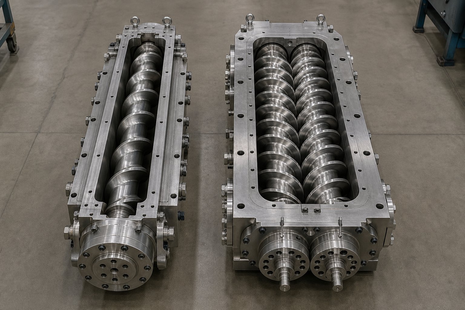
Choosing the right screw type is only half the equation. The other half — and arguably the more expensive half — involves deciding whether your extruder needs one screw or two. This isn't a minor distinction. The gap between single-screw and twin-screw architectures affects everything from capital cost and floor space to mixing intensity and the range of polymers you can realistically process.
Single-Screw Extruder Advantages and Limitations
Single-screw extruders remain the workhorse of the plastics industry for a reason. They're mechanically simpler, significantly less expensive to purchase and maintain, and perfectly suited for applications where the primary job is steady-state melting and pumping of a consistent feedstock. Film extrusion, pipe and profile production, sheet lines, and wire coating — these are the domains where a single-screw machine genuinely excels.
The operating principle is straightforward: one rotating screw uses drag flow — friction between the polymer and the barrel wall — to convey material forward. This simplicity translates to lower capital outlay, easier operator training, and reduced spare parts inventory. Entry-level single-screw extruders suitable for basic applications typically range from $30,000 to $80,000, while industrial-scale systems with advanced features fall between $200,000 and $500,000. Used single screw extruders bring that barrier even lower for operations with tight budgets.
Where do single-screw designs fall short? Mixing. A single screw has limited ability to disperse additives, homogenize polymer blends, or handle feedstocks with inconsistent bulk density — like flakes, powders, or recycled regrind. Fine powders tend to slip against the screw and barrel surface rather than generating the friction needed to move forward, leading to erratic output. Compounding, reactive processing, and highly filled formulations push the single-screw architecture beyond what drag flow alone can deliver.
Co-Rotating vs Counter-Rotating Twin-Screw Systems
Twin-screw extruders solve the mixing problem by replacing drag flow with positive displacement. Two intermeshing screws physically push material forward regardless of friction conditions, giving you far more control over challenging feedstocks. But "twin-screw" isn't a single category — the direction those screws rotate creates two fundamentally different machines.
Co-rotating intermeshing twin screws spin in the same direction. At the meshing point, one screw pulls material into the gap while the other pushes it out, forcing material through an "∞" shaped path that generates exceptional distributive and dispersive mixing. The self-wiping geometry — where each screw continuously scrapes the other — prevents material stagnation and reduces degradation risk. This configuration dominates compounding, masterbatch production, glass-fiber reinforcement, and reactive extrusion. The twin screw and barrel assembly in co-rotating systems is typically modular, letting processors reconfigure screw elements for different formulations without replacing the entire shaft.
Counter-rotating intermeshing twin screws spin in opposite directions, creating a calendering effect as material is squeezed between the screws at the nip point. This generates lower shear than co-rotating designs, which is exactly the advantage for processing PVC — a polymer that degrades rapidly under high-shear conditions. Counter-rotating systems are the standard for PVC pipe, profile, and window frame extrusion, where gentle fusion and tight pressure control matter more than intense mixing.
The cost difference is substantial. Production-scale twin screw extruders commonly range from $300,000 to $800,000, with high-performance industrial systems exceeding $1,500,000. A used twin screw extruder can reduce that initial outlay, though you'll want to inspect the twin screw barrel closely for wear patterns before committing — especially if the machine processed abrasive filled compounds in its previous life. When evaluating whether a used twin screw extruder for sale represents genuine value, always request flight-to-barrel clearance measurements and screw element wear documentation.
Maintenance complexity also scales with the number of screws. Annual maintenance costs for twin-screw extruders typically range from $8,000 to $25,000 for routine service, with complete screw element sets costing $20,000 to $100,000 depending on configuration — compared to $3,000 to $15,000 annually and $3,000 to $15,000 per screw replacement for single-screw systems.
| Feature | Single-Screw | Co-Rotating Twin | Counter-Rotating Twin |
|---|---|---|---|
| Mixing Capability | Basic; limited to shear-driven melting and modest homogenization | Excellent; high-intensity distributive and dispersive mixing with self-wiping action | Moderate; gentle calendering effect suited to shear-sensitive polymers |
| Throughput Range | 10–2,000+ kg/hr depending on screw diameter | 100–2,500+ kg/hr; higher specific throughput per mm of diameter | 50–1,500 kg/hr; optimized for controlled output rather than maximum rate |
| Best Polymer Types | PE, PP, PS, PET — commodity resins with consistent feedstock | Compounds, masterbatch, engineering resins, recycled blends, filled systems | PVC (rigid and flexible), some thermoset and heat-sensitive formulations |
| Capital Cost | $30,000–$500,000 | $150,000–$1,500,000+ | $120,000–$800,000 |
| Maintenance Complexity | Low; simple design, fewer wearing components, in-house service feasible | High; modular screw elements, precision gearbox, specialized service required | Moderate to high; less modular than co-rotating, but still complex gearing |
| Residence Time Control | Limited; governed primarily by screw speed and back pressure | Precise; metered starve-feeding decouples throughput from screw speed | Good; positive conveying provides consistent material advancement |
The decision framework boils down to a straightforward question: does your process demand mixing, or is it primarily about conveying and melting? If you're running PE pipe on a dedicated line, a single-screw system delivers what you need at a fraction of the twin-screw cost. If you're compounding glass-filled nylon or producing color concentrates, no amount of mixing elements on a single screw matches what co-rotating twin-screw architecture inherently provides.
Yet regardless of which configuration sits on your factory floor, one variable remains constant — the screw must be designed for the specific polymer family it processes. And the differences between how semi-crystalline, amorphous, filled, and heat-sensitive materials interact with screw geometry run deeper than most processors realize.
Matching Screw Design to Polymer Families
Here's where theory meets the factory floor. You can understand every geometry parameter, know every screw type by name, and still end up with a process that fights you — if the screw doesn't match the polymer running through it. The interaction between resin behavior and screw design is so specific that a configuration optimized for polyethylene can produce disastrous results with polycarbonate. No amount of barrel temperature adjustment or RPM tuning compensates for a fundamental mismatch between the extruder screw and barrel geometry and the material it's asked to process.
Screw Design for Semi-Crystalline vs Amorphous Polymers
Semi-crystalline polymers — polyethylene, polypropylene, nylon — behave differently from amorphous resins during melting, and that difference dictates nearly every dimension on the screw. These materials have a sharp, well-defined melting point rather than a gradual softening range. Below that temperature, the solid pellet remains rigid and resists deformation. Above it, the crystalline structure collapses rapidly into a low-viscosity melt. That sudden phase change demands higher compression ratios to generate enough shear energy to push through the transition.
As plastics processing expert Jim Frankland explains, PE screws typically use a 3:1 compression ratio as a starting point, while nylon screws typically start at 4:1. These aren't arbitrary numbers — they reflect the significant energy input each polymer requires to fully melt. Semi-crystalline resins also benefit from longer feed zones, sometimes occupying up to half the total screw length, because they need more conveying distance to build frictional heat before compression can begin meaningful melting.
Amorphous polymers like polystyrene, ABS, and polycarbonate behave in a fundamentally different way. They soften progressively over a broad temperature range, with no discrete melting point to overcome. This gradual transition means lower compression ratios — typically 2:1 to 2.5:1 — generate sufficient shear without over-working the material. Shorter feed zones work effectively because softening begins earlier in the process, and the compression zone can start its work sooner.
The practical takeaway? Running a 4:1 compression screw with polycarbonate risks excessive shear heating that degrades the resin and produces yellowed, brittle product. Running a 2:1 compression screw with HDPE risks incomplete melting and unmelted particles in the extrudate. The barrel and screw must be matched to the resin — not the other way around.
Handling Filled, Reinforced, and Heat-Sensitive Materials
Filled and reinforced compounds introduce an entirely separate set of challenges. Glass-fiber-filled nylon, for example, demands a screw and barrel combination that balances two competing needs: enough mixing to disperse fibers uniformly, but gentle enough shear to preserve fiber length. Aggressive mixing elements or high compression ratios break long fibers into short fragments, dramatically reducing the mechanical properties that justified adding the reinforcement in the first place. The ideal approach often pairs a moderate compression ratio (around 2.5:1) with distributive mixing elements — pins or pineapple sections rather than high-shear Maddock mixers.
Abrasive fillers like glass fiber, calcium carbonate, and mineral additives also accelerate screw and barrel wear at alarming rates. Processing glass-filled nylon on an uncoated nitrided screw may yield severely limited operational life, making wear-resistant coatings or bimetallic construction essential rather than optional. The extruder screw and barrel specification for filled compounds should always begin with wear resistance, not geometry.
PVC sits in a category of its own. It's heat-sensitive, prone to degradation from excessive shear, and releases corrosive hydrochloric acid gas when overheated. Standard compression ratios don't apply — PVC needs low compression (around 2:1), minimal shear, and absolutely no dead spots where material can stagnate and degrade. Screw channels must be streamlined with smooth transitions, and chrome-plated or corrosion-resistant barrel and screw surfaces are mandatory.
Fluoropolymers like PTFE and FEP push the requirements even further. They generate corrosive off-gases during processing that attack standard tool steels, requiring Hastelloy or nickel-alloy barrel liners and corrosion-resistant screw substrates. Compression ratios stay extremely low, and metering zones run long to minimize shear-induced degradation.
The following quick reference maps the most common polymer families to their recommended screw configurations:
- PE (HDPE, LDPE, LLDPE): Compression ratio 2.5:1–3.5:1; long feed zone (~50%); standard three-zone or barrier screw; grooved feed throat recommended for HMWPE.
- PP (homopolymer and copolymer): Compression ratio 2.5:1–3.5:1; moderate-to-long feed zone (~40–50%); barrier screw preferred for high-output applications.
- Nylon (PA6, PA66): Compression ratio 3.5:1–4:1; moderate feed zone (~35–40%); vented screw recommended to remove moisture; wear-resistant coatings essential for glass-filled grades.
- PS and ABS: Compression ratio 2:1–2.5:1; shorter feed zone (~30–35%); general-purpose screw adequate for most applications; mixing section helpful for color-critical runs.
- PC (polycarbonate): Compression ratio 2:1–2.5:1; moderate feed zone (~30–35%); vented screw strongly recommended to remove absorbed moisture; low-shear mixing elements preferred.
- PVC (rigid and flexible): Compression ratio 1.8:1–2.2:1; short feed zone (~25–30%); no dead spots; chrome or corrosion-resistant barrel and screw surfaces required; counter-rotating twin screw for profile extrusion.
- PET: Compression ratio 2.5:1–3:1; moderate feed zone; vented or vacuum-vented screw essential for moisture removal; barrier screw recommended for sheet and fiber.
- Glass-fiber-filled compounds: Compression ratio 2:1–2.5:1 regardless of base resin; distributive mixing preferred over dispersive; tungsten carbide or bimetallic barrel and screw construction mandatory for acceptable wear life.
- Fluoropolymers (PTFE, FEP, PFA): Compression ratio 1.5:1–2:1; extended metering zone; corrosion-resistant Hastelloy or nickel-alloy barrel liners and screw materials required.
This list isn't exhaustive, but it captures the critical principle: there is no ideal compression ratio for a specific polymer without consideration of many other variables, including bulk density, particle geometry, melt temperature targets, and even hopper design. Recyclate compounds the challenge further, because a low-bulk-density regrind may need extra feed depth that conflicts with the standard compression ratio for that resin — meaning feeding and melting requirements should be determined separately rather than relying on textbook defaults.
Getting the polymer-to-screw match right is the foundation. But even a perfectly designed screw geometry fails prematurely if it's built from the wrong metal or lacks the appropriate surface treatment for the material it contacts. That's the dimension most processors overlook entirely — and the one that determines whether a screw lasts six months or six years.
Screw Materials, Coatings, and Wear-Resistance Selection
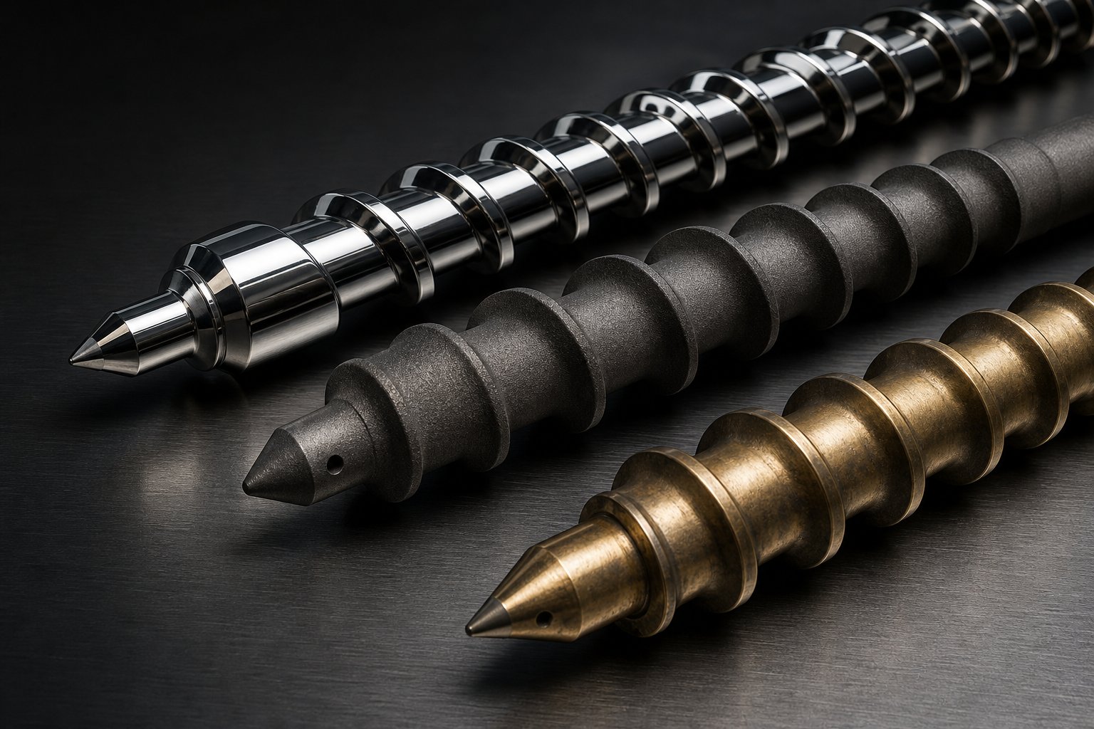
A screw with perfect geometry built from the wrong metal is an expensive mistake waiting to happen. You can nail every compression ratio, zone proportion, and mixing element — and still face premature failure if the metallurgy can't handle the polymer and fillers running through it. Yet most processors spend hours debating L/D ratio and minutes — if any time at all — evaluating base metals and surface treatments. That imbalance costs real money in downtime, replacement frequency, and degraded output quality.
Base Metal Options for Extruder Screws
The vast majority of screws and barrels in operation today use one of three base material categories, each representing a different trade-off between cost, hardness, and wear life.
Nitrided alloy steel (4140/4340 or the equivalent 38CrMoAlA) accounts for roughly 80% of the extrusion and injection screw market. During manufacturing, the steel is quenched and tempered to a core hardness of 28–32 HRC, then gas- or ion-nitrided to create a surface layer reaching HV 900–1020 (approximately HRC 57–65). The result is a hard outer shell over a tough, ductile core — economical and perfectly adequate for processing clean commodity resins like PE, PP, PS, and standard ABS.
The catch? That hardened layer is typically only 0.5–0.8 mm thick. Once abrasive fillers wear through it, the soft base material underneath erodes rapidly, and the wear rate accelerates exponentially. You can't locally repair a worn-through nitrided surface — the screw gets scrapped.
Bimetallic construction solves that thin-layer limitation by applying a thick deposit of wear-resistant alloy — typically nickel-based (such as Colmonoy 56), cobalt-based, or iron-based with tungsten carbide particles — onto the screw flights via plasma transferred arc (PTA) welding, or centrifugally cast into the bore of extruder barrels. The alloy layer reaches 1.5–2.5 mm thick — more than three times the depth of a nitrided layer. This makes bimetallic screws and barrels the go-to choice for wood-plastic composites, high-calcium PVC, glass-fiber-reinforced engineering plastics, and recycled material lines where abrasive contaminants are unavoidable. Under these harsh conditions, bimetallic service life typically runs 2 to 3 times longer than nitrided equivalents — and some bimetallic components can be re-welded when the coating reaches its wear limit, extending the useful life of the base material even further.
Through-hardened tool steels (D2, H13) and CPM powder metallurgy steels represent the top tier. Unlike nitrided or bimetallic approaches that harden only the surface, tool steel screws are hard from flight tip to root. Traditional D2 and H13 achieve HRC 58–62, while CPM grades like 9V and 10V — produced via hot isostatic pressing of metal powders — deliver exceptionally uniform carbide distribution and the highest abrasion resistance currently available. CPM 9V has become the industry standard material for high-performance injection molding screws and barrels as well as extrusion screws processing heavily glass-filled engineering plastics (30–50% glass fiber content), where abrasive scouring attacks the screw root in areas that bimetallic coatings don't cover.
The trade-off is cost — tool steel screws typically run 3 to 4 times the price of nitrided alternatives — along with longer lead times and, for the highest-hardness CPM grades, reduced toughness that introduces fracture risk under extreme torque or impact events.
Surface Coatings and Wear-Resistance Technology
Base metal isn't the whole story. Surface coatings add a second layer of defense — or, in some cases, the primary one — by modifying the screw's outermost contact surface without changing its core properties.
Chrome plating is the classic corrosion barrier. A hard chrome layer provides a smooth, low-friction surface that resists chemical attack from corrosive polymers like PVC (which releases hydrochloric acid) and certain flame-retardant formulations. It's relatively affordable and widely available, but it offers limited abrasion resistance — you wouldn't rely on chrome alone when running mineral-filled compounds through your extrusion barrels.
Tungsten carbide coatings, applied via thermal spray (HVOF) processes, deliver the highest abrasion resistance available as a surface treatment. These coatings create extremely hard wear surfaces ideally suited for the most demanding filled-compound applications. Tungsten carbide treatments typically cost $20,000–$35,000 for a complete screw, but they're justified when conventional materials would require replacement every few months. Think high-concentration glass fiber, mineral-loaded masterbatch, or recycled streams with metallic contaminants.
PVD and CVD coatings — physical and chemical vapor deposition — represent the newer frontier. Coatings like chromium nitride (CrN) and titanium nitride (TiN) deposit thin films (2–5 microns) with hardness values reaching 2000–3000 HV. These excel at reducing adhesive wear — where sticky polymers bond to the screw surface and tear material away during rotation — and can extend service life by 3 to 4 times in adhesion-prone applications. They're particularly effective for processing nylon, PVC, and certain engineering resins that tend to stick to metal surfaces.
Stellite hard-facing applies cobalt-based alloy to screw flight tips and lands, providing exceptional resistance to both abrasion and corrosion at elevated temperatures. It's a common specification for extruder barrels and screws in demanding compounding environments where both wear mechanisms attack simultaneously.
Imagine processing 30% glass-filled nylon on a standard nitrided screw. Typical abrasive wear rates for high-concentration glass fiber compounds can reach 1.5–3.0 mm per year of continuous operation. With a nitrided layer only 0.5–0.8 mm deep, you're looking at wear-through in months, not years. Switch to a bimetallic or tungsten-carbide-coated alternative, and that same application runs for two to five times longer before replacement becomes necessary. The upfront cost is higher, but the total cost of ownership drops dramatically when you factor in reduced downtime, fewer replacements, and consistent output quality.
| Material/Coating | Hardness Range | Best For | Relative Cost | Expected Wear Life Improvement |
|---|---|---|---|---|
| Nitrided Steel (4140/4340/38CrMoAlA) | HV 900–1020 surface (HRC 57–65); core 28–32 HRC | Unfilled commodity resins (PE, PP, PS, ABS) | 1× (baseline) | Baseline — adequate for non-abrasive, non-corrosive applications |
| Bimetallic Alloy (Ni-based, e.g., Colmonoy 56) | HRC 50–55 | Filled compounds, WPC, recycled materials, high-calcium PVC | 1.5–2× | 2–3× vs. nitrided; up to 5× in highly abrasive applications |
| Through-Hardened Tool Steel (D2, H13) | HRC 58–62 | Moderately filled engineering plastics, high-torque applications | 2–2.5× | 2–3× vs. nitrided; uniform hardness from surface to root |
| CPM Powder Metallurgy (9V, 10V) | HRC 58–64 | 30–50% glass-fiber-filled PA/PBT; extreme abrasion environments | 3–4× | 4–5× vs. nitrided; protects screw root where coatings can't reach |
| Hard Chrome Plating | HRC 65–70 | Corrosive resins (PVC, halogenated flame retardants); release improvement | 0.3–0.5× (additive to base) | Minimal abrasion benefit; primarily extends life against chemical attack |
| Tungsten Carbide Coating (HVOF) | HV 1200–1400 | Extreme abrasion — high glass-fiber loading, mineral fillers, metallic contaminants | 0.6–1× (additive to base) | 3–5× vs. nitrided in severe abrasive conditions |
| PVD/CVD Coatings (CrN, TiN) | HV 2000–3000 | Adhesive wear reduction — sticky polymers (PA, PVC, some engineering resins) | 0.4–0.7× (additive to base) | 3–4× vs. uncoated screws in adhesion-prone applications |
| Stellite Hard-Facing (Co-based) | HRC 38–55 (varies by grade) | Combined abrasion and corrosion at elevated temperatures; flight tip protection | 0.5–0.8× (additive to base) | 2–3× vs. nitrided for combined wear mechanisms |
The decision isn't just about picking the hardest option — it's about matching the dominant wear mechanism to the right defense. Abrasive wear from glass fiber calls for tungsten carbide or CPM steel. Corrosive attack from PVC or flame retardants demands chrome or corrosion-resistant bimetallic alloys. Adhesive wear from sticky engineering resins responds best to PVD coatings that create low-friction release surfaces. And for many processors running mixed production schedules across multiple polymer families, a bimetallic screw offers the best all-around compromise between cost and versatility.
Selecting the right metallurgy protects your investment in screw geometry. But even the best material eventually wears — and knowing exactly when a screw has crossed the line from "still performing" to "silently costing you money" requires a systematic inspection and measurement protocol that most maintenance teams never formalize.
Screw Maintenance, Inspection, and Replacement Protocols
A screw that looked perfect on the day it was installed doesn't stay that way forever. Wear is gradual — so gradual, in fact, that most processors don't notice it until scrap rates spike, energy consumption climbs, or output mysteriously drops at the same RPM that ran fine six months ago. By that point, you've already been losing money for weeks or months without realizing it. The difference between reactive maintenance and a proactive inspection program often comes down to whether you measure your extruder screws and barrels on a schedule — or only when something breaks.
Measuring Screw Wear and Documenting Condition
Wear announces itself through symptoms before it ever causes catastrophic failure. Watch for these three warning signs that something has changed inside the barrel:
- Output drop at the same screw speed — melt leaks backward over worn flights instead of being pumped forward.
- Rising melt temperature — increased leakage flow and higher RPM needed to compensate both add heat to the polymer.
- Surging and dimensional variation — opened clearances destabilize pumping, causing pressure fluctuations that show up as inconsistent product dimensions.
These symptoms point toward wear, but measurement confirms it. Guessing isn't a maintenance strategy. When you pull the screw for inspection, a systematic protocol ensures nothing gets missed and every data point gets logged for trend analysis over time.
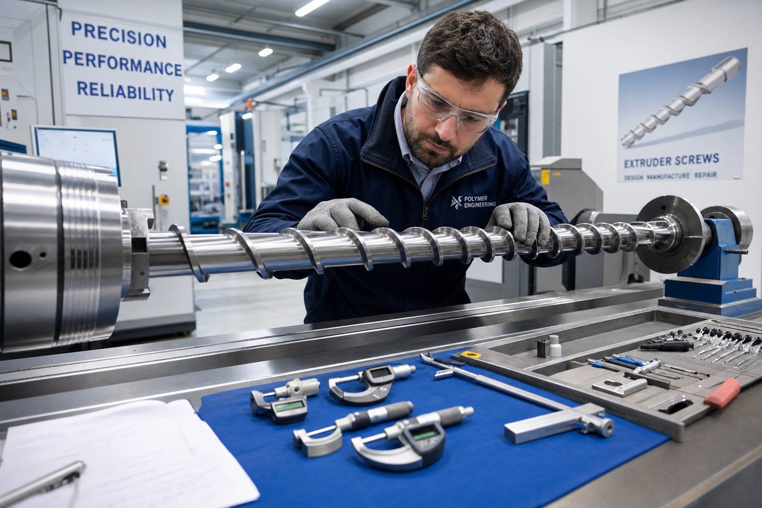
- Record baseline data before the first run. Measure and log the flight outer diameter at every turn along the screw's length using a flight micrometer. Record root diameters and note the measurement location and direction. This becomes the reference document every future inspection compares against.
- Measure the barrel bore with a bore gauge. Clearance is the sum of screw wear and barrel wear — a tired screw in a worn barrel is worse than either measurement alone. Always measure both components.
- Calculate flight clearance at each measurement point. Subtract the screw flight OD from the barrel bore diameter, then divide by two for per-side clearance. Compare this value to the as-new clearance on the original drawing.
- Inspect flights visually for edge condition. Screw flights should maintain their squared edges. Placing a smaller screw on a precision granite block provides a quick visual check for flight rounding and straightness. Chrome-plated screws should show no flaking, peeling, or worn-through areas.
- Check for cracking at flight roots. Root wear is typically most severe in high-pressure zones — the transition section and the last few turns of metering. Look for cracks, pitting, and wash-out on the forwarding side of flights, which indicates material has been scouring the metal under pressure.
- Verify straightness. If a clean screw doesn't freely slide into a clean barrel, remove it and reinsert backward. If it slides freely in reverse, the problem is typically at the back end of the screw. If it binds both directions, the screw may need straightening or replacement.
- Inspect barrier flights and mixer differentials. These undercut geometries are critical for performance. As barrier flights wear, the barrier design loses its ability to separate the solid bed from the melt pool, and melting efficiency drops. Even small clearance changes in these areas affect output quality disproportionately.
- Document everything. Log all measurements, note visual anomalies, photograph any areas of concern, and date the record. Trend data over multiple inspections reveals wear rates that let you predict replacement timing rather than reacting to failure.
How often should you perform these measurements? That depends on what you process. Graham Engineering recommends basing maintenance intervals on run-time hours rather than calendar dates — a machine that ran only 300 hours during a calendar year doesn't need the same inspection frequency as one running three shifts daily. If you're processing abrasive glass-filled or mineral-filled compounds, inspect more frequently. Clean commodity resins allow longer intervals between pulls.
Rebuild vs Replace Decision Criteria
The core wear limit for most extrusion applications follows a straightforward rule: replace the screw when flight clearance reaches approximately twice its as-new value. The as-new clearance is roughly the screw diameter divided by 1,000 per side. For a 100 mm screw, that means new clearance of about 0.1 mm per side, with replacement triggered at roughly 0.2 mm.
But "acceptable" isn't a single number — it depends on what you make. Non-critical products like corrugated pipe can tolerate wear well past the 2x threshold, while precision film, medical tubing, and tight-tolerance profiles need replacement right at that point because they can't absorb the output and quality drift that worn clearances cause.
Here's a telling number that puts the economics in perspective: a roughly 10% decrease in screw OD can cut output by as much as 25%. At that point, you're paying more in lost production capacity and wasted material than a new extruder screw barrel assembly would cost.
When wear reaches the limit, you face two options:
- Rebuild (refurbish): Worn flights are re-hardfaced with abrasion-resistant alloys and ground back to original OEM dimensions. An experienced screw manufacturer can rebuild worn screws to like-new condition for a fraction of new-screw cost. However, industry guidance suggests that a screw should generally not be refurbished more than about three times, because repeated welding gradually deteriorates the base metal and risks delamination between the hardfacing and substrate. With high-quality welding and proper metallurgical practices, some manufacturers have successfully rebuilt screws six to eight times — but this demands expertise and careful inspection of substrate integrity at each cycle.
- Replace: For a screw already rebuilt several times, one with deep root damage, a bent shaft, or a design that's simply outdated, a new screw makes better economic sense. Critically, never drop a fresh or rebuilt screw into a worn barrel — clearance depends on both components, and a new screw paired with a worn barrel won't restore the seal you need.
Before deciding, ask four questions that experienced screw manufacturers use to evaluate rebuild candidates: How severe is the overall wear? What are the wear characteristics — abrasive, corrosive, adhesive, or a combination? Can the current screw design be improved rather than simply replicated? And can the surface treatment be upgraded to extend the next service interval?
Sometimes the best rebuild decision is to not rebuild the same design at all. If the original screw was a generic configuration that never matched your polymer particularly well, a replacement built with optimized geometry and upgraded metallurgy can deliver better throughput, lower scrap, and longer wear life than the original ever provided. For processors, equipment manufacturers, and maintenance teams sourcing custom or OEM-replacement solutions for both injection molding barrel and screw sets and extrusion equipment, working with specialized manufacturers ensures dimensional accuracy and material specifications match the original equipment requirements. NANHAIYA's screw barrel product center offers configurations for extrusion and injection molding screws with engineering consultation for material and geometry selection — including the ability to reverse-engineer worn components when original drawings are unavailable.
The inspection data you collect doesn't just tell you when to replace — it shapes what to replace with. Wear patterns reveal which zones take the most punishment, which polymers are most aggressive, and whether your current metallurgy is adequate. That information feeds directly into the screw selection process, turning reactive maintenance into a strategic decision that improves performance with every replacement cycle.
Screw Selection Framework and Sourcing Guidance
You've seen how geometry, zone design, screw type, polymer pairing, metallurgy, and wear inspection all interconnect. Individually, each topic is useful. Together, they form a decision framework — a repeatable process that takes you from "I need a screw" to "I need this specific screw, built from this material, with these dimensions, for this polymer." Most processors skip that structured approach, defaulting to whatever they ran last time or whatever the lowest bidder offers. That shortcut is exactly what leads to mismatched configurations, premature wear, and the kind of chronic process frustration this entire article is built to eliminate.
Step-by-Step Screw Selection Process
Think of screw selection as a series of filters. Each question narrows the field until you arrive at a configuration that fits your specific operation — not a generic recommendation, but a targeted specification grounded in your polymer, your throughput targets, and your production economics.
- Identify your polymer family and its thermal behavior. Is it semi-crystalline (PE, PP, nylon) or amorphous (PS, ABS, PC)? Semi-crystalline resins demand higher compression ratios (3:1–4:1) and longer feed zones. Amorphous polymers tolerate lower compression (2:1–2.5:1) and shorter feed sections. PVC sits in its own category — low compression, minimal shear, no dead spots. Start here because this single variable determines your compression ratio range, zone proportions, and whether you need corrosion-resistant construction.
- Define your target output rate and quality requirements. A general-purpose three-zone screw handles moderate throughput of commodity resins efficiently. Pushing for higher output — especially with engineering resins — typically calls for a barrier screw that separates solids from melt more aggressively. Precision applications like medical tubing or optical film demand tighter tolerances and more consistent melt delivery than a GP screw can provide.
- Determine whether intensive mixing is required. Are you dispersing color concentrates, blending additives, or compounding filled materials? If so, you need dedicated mixing elements — Maddock sections for dispersive action against hard agglomerates, pin or pineapple mixers for gentle distributive blending. If your material is a clean, single-resin feedstock with no additives, mixing sections add unnecessary pressure drop and cost.
- Assess whether venting is necessary. Hygroscopic polymers like nylon, PC, and PET absorb moisture that causes splay and bubbles without removal. Recycled materials often carry residual volatiles. If your process requires in-line devolatilization, specify a vented two-stage screw with adequate L/D (30:1 minimum) and vacuum-capable barrel hardware.
- Evaluate filler type and loading level. Glass fiber above 15% weight demands wear-resistant metallurgy — bimetallic construction at minimum, CPM tool steel or tungsten carbide coatings for loadings above 30%. Mineral fillers like calcium carbonate and talc are softer but still drive significant flight wear at high concentrations. Unfilled commodity resins run acceptably on standard nitrided steel.
- Calculate expected production volume and run-time hours. This determines your wear-life requirement. A screw running three shifts daily on abrasive compounds needs premium metallurgy to avoid replacement every few months. A screw running intermittently on clean resin may justify standard nitrided construction because the wear interval comfortably exceeds your maintenance cycle. The question of how much do screws cost is never answered accurately by the purchase price alone — it's answered by dividing total cost of ownership (purchase + downtime + labor + scrap + energy penalty) by the hours of acceptable service life delivered.
- Map your answers to a configuration. By this point, your polymer has defined the compression ratio and zone proportions. Your output target has narrowed the screw type (GP, barrier, or barrier-plus-mixer). Your additive and volatile situation has determined whether you need mixing elements or venting. Your filler loading has specified the metallurgy tier. And your production volume has set the wear-life threshold that validates or rejects that metallurgy choice on economic grounds.
This sequence isn't theoretical. It mirrors the engineering consultation process that experienced screw designers walk through with every custom specification. The processors who get screw selection wrong almost always skip one or more of these steps — most commonly steps 5 and 6, where metallurgy and total cost of ownership get overlooked in favor of upfront price.
Where to Source Custom and Replacement Screws
Finding the right screw design is only half the challenge. Finding a supplier who can actually build it to specification — and verify that it meets dimensional and metallurgical requirements — is the other half. Not all screw manufacturers are created equal, and the gap between a precision-built component and a commodity knock-off shows up in field life, output consistency, and the frequency of your replacement orders.
When evaluating suppliers, prioritize these capabilities:
- Engineering support: Can the supplier's team help you select the right geometry and material for your specific polymer and process conditions? A supplier who simply takes your drawing and quotes a price provides less value than one who reviews your application and suggests improvements. This matters especially when you're replacing a worn screw and considering design upgrades rather than simply replicating the original.
- Material certifications: Demand EN 10204 3.1 certificates for every alloy used — base material, hardfacing overlays, and barrel liners. Hardness testing per ASTM E18 or E92 at multiple points along the assembly verifies that heat treatment and overlay application met specification uniformly, not just at one convenient spot.
- Dimensional tolerancing: Flight OD, root diameter, and flight clearance must be held to tight tolerances that match original equipment specifications. CMM (coordinate measuring machine) inspection data should accompany every shipment. A screw that's 0.1 mm oversize on the flight OD won't fit the barrel; one that's 0.1 mm undersize defeats the purpose of replacement.
- Reverse-engineering capability: When original drawings are unavailable — common with older machines, used extruders acquired without documentation, or legacy equipment from manufacturers no longer in business — the supplier must be able to accurately measure a worn screw and reconstruct the original design intent. This is particularly relevant for processors who acquire a Davis-Standard extruder or similar established-brand equipment on the secondary market. Whether you've purchased a davis standard extruder for sale through an auction, a broker, or directly from another processor, obtaining replacement screws requires a supplier with the metrology equipment and application knowledge to work backward from worn components to correct specifications.
- Support for both single-screw and twin-screw configurations: Many facilities run a mix of US extruders and imported equipment across different product lines. A supplier who handles only one category forces you to manage multiple vendor relationships, splitting your purchasing leverage and complicating quality management.
For processors, equipment manufacturers, and maintenance teams seeking custom or OEM-replacement screw and barrel solutions, NANHAIYA's product center offers configurations for extrusion and injection molding equipment with engineering consultation for material and geometry selection. Their capability spans single-screw and twin-screw designs, including reverse-engineering of worn components when original documentation is unavailable — a practical necessity for operations running legacy or secondhand machinery.
One final consideration that experienced procurement teams understand: the screw and barrel together represent a small fraction of your extruder's total capital cost, yet they govern the majority of its operating economics. A 2026 market analysis places the global feed screw and barrel market at nearly $2 billion, growing at 6.9% annually — driven largely by the shift toward bimetallic construction and advanced coatings that deliver longer service life and lower total cost of ownership. The market is moving up the materials curve because the math overwhelmingly favors it.
Proper screw selection is an investment that pays returns through reduced energy consumption, higher throughput, lower scrap rates, and extended equipment life — the cheapest screw to buy is almost never the cheapest screw to own.
Every topic covered in this article — geometry parameters, zone design, screw types, polymer matching, metallurgy, wear measurement, and supplier qualification — connects to that single principle. The processors who treat screw selection as a strategic engineering decision, rather than a commodity purchasing task, consistently run more efficient lines, produce higher-quality product, and spend less on maintenance over the life of their equipment. That's the competitive advantage hiding inside a component most people never think about until it fails.
Frequently Asked Questions About Plastic Extruder Screws
1. What are the three zones of a plastic extruder screw and what does each do?
The feed zone uses deep flights to grab solid pellets and convey them forward through barrel-wall friction. The compression zone gradually reduces channel depth to squeeze out trapped air and initiate melting via shear energy and conducted heat. The metering zone maintains a constant shallow depth to deliver a uniform, pressurized melt to the die. Zone proportions shift by polymer type - polyolefins need longer feed zones (~50%) while PVC requires a longer metering zone (~30-35%) and very gradual compression to prevent thermal degradation.
2. How do I choose the right compression ratio for my polymer?
Compression ratio depends on whether your resin is semi-crystalline or amorphous. Semi-crystalline polymers like PE and PP typically need 2.5:1 to 3.5:1 because their sharp melting point demands higher shear energy. Nylon may require up to 4:1. Amorphous resins like PS, ABS, and PC soften gradually and work well at 2:1 to 2.5:1. PVC is uniquely heat-sensitive and calls for ratios as low as 1.8:1 to 2.2:1. However, compression ratio alone does not fully define screw behavior - absolute channel depths, bulk density, and filler content all influence the ideal specification.
3. What is the difference between a barrier screw and a general-purpose screw?
A general-purpose (GP) screw uses a single continuous flight across feed, compression, and metering zones. It is versatile, affordable, and easy to maintain but has limited melting capacity at high output rates and minimal mixing ability. A barrier screw adds a secondary flight in the compression zone that physically separates the unmelted solid bed from the growing melt pool. Only fully molten polymer can pass over the barrier flight, which virtually eliminates unmelted particles in the output. Barrier screws are preferred for high-output film, precision profiles, and engineering resins where melt consistency is critical.
4. How much do extruder screws cost and what affects the price?
The purchase price of an extruder screw varies widely based on diameter, length, metallurgy, and design complexity. Standard nitrided steel screws represent the baseline cost. Bimetallic screws with wear-resistant alloy overlays typically cost 1.5 to 2 times more, while CPM powder metallurgy tool steel screws run 3 to 4 times the baseline. Tungsten carbide coatings can add $20,000 to $35,000 to the total. However, experienced processors evaluate total cost of ownership - factoring in downtime, replacement frequency, scrap, and energy penalties - rather than upfront price alone. Suppliers like NANHAIYA (nhyscrew.com/products) offer engineering consultation to help match metallurgy and geometry to your specific application for optimal long-term value.
5. When should I replace my extruder screw instead of rebuilding it?
A common guideline is to replace the screw when flight-to-barrel clearance reaches approximately twice the as-new value. For a 100 mm screw, that means per-side clearance growing from about 0.1 mm to 0.2 mm. Rebuilding via hardfacing is cost-effective when the base metal is sound and the screw has been rebuilt fewer than three times, though skilled manufacturers have managed six to eight rebuilds. Full replacement makes more economic sense when the shaft is bent, root damage is severe, or the original design was suboptimal for your current polymer. Notably, a roughly 10% decrease in screw OD can cut output by as much as 25%, so delaying replacement carries hidden costs in lost capacity and increased scrap.
Written by
Nanhaiya Technical Team
Zhoushan Nanhaiya Plastic Machinery Co., Ltd.
The Nanhaiya technical team supports screw and barrel manufacturing projects through application review, technical communication, custom manufacturing coordination, and production and quality control.
Discuss Your Application
Related Articles
More insights on screw barrel technology and plastics processing.

What Nobody Tells You About Screw Barrel For Plastic Machine Design
Oct 10, 2026
Learn how screw barrel for plastic machine design affects melt quality, throughput, and wear life. Covers geometry, resin matching, troubleshooting, and sourcing.
Read Article
Single Screw Extruder for Sheet: Stop Guessing, Start Specifying
Oct 9, 2026
Learn how to specify a single screw extruder for sheet production. Covers screw geometry, resin-specific processing, troubleshooting, and maintenance best practices.
Read Article
PE Pipe Extruder Machine: What Datasheets Won't Tell You
Oct 9, 2026
Learn how a PE pipe extruder machine works, key specs explained, material grade selection, maintenance tips, and buyer guidance beyond the datasheet.
Read ArticleLooking for something else?
Search by material, symptom or product and jump straight to the relevant page.
These are navigation suggestions based on keyword matching — not a quotation, not a delivery commitment, and not a substitute for engineering review. Final specification is confirmed by our engineers against your drawings and processed material.
Need help with screw barrel selection?
Share your machine model, processed material and application. Our team can help with pricing and technical support.