

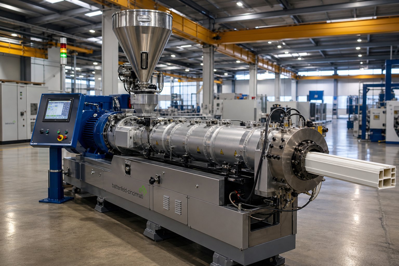
What Is a Plastic Extruder Machine and Why It Matters
A plastic extruder machine is industrial equipment that continuously melts raw polymer — pellets, granules, or flakes — and forces it through a shaped die to produce a uniform profile. In simpler terms, raw material goes in one end, heat and pressure transform it into a molten stream, and a finished shape exits the other end without interruption.
A plastic extruder machine continuously melts and shapes raw polymer by pushing it through a heated barrel via a rotating screw, then forcing the molten material through a die to create products such as pipes, films, sheets, and profiles.
Definition and Core Function of a Plastic Extruder Machine
Imagine feeding a handful of tiny plastic pellets into one side of a machine and watching a perfectly formed pipe, sheet, or cable jacket emerge from the other side — all without stopping. That is exactly what a plastic extrusion machine does, and it does it around the clock in factories worldwide.
The core function revolves around three simultaneous actions:
- Conveying — A rotating screw moves raw polymer forward through a heated barrel.
- Melting — A combination of external heaters and internal friction (shear heat) transforms solid pellets into a homogeneous melt.
- Shaping — The molten polymer is pushed through a die that defines the product's cross-sectional profile, then cooled and solidified downstream.
Because the screw never stops turning, the process is inherently continuous. That single characteristic — continuous output — is what separates extrusion from most other plastics processes and makes it one of the highest-volume manufacturing methods in the polymer industry. Pipes can be produced in virtually unlimited lengths, films can run for thousands of meters on a single roll, and profiles can be cut to any size on the fly. Extruders also play a critical role in recycling operations, where post-consumer flakes are re-melted and pelletized for reuse.
Why Extrusion Stands Apart from Other Plastic Processes
If extrusion creates continuous linear shapes, what handles everything else? You will encounter three other major processes repeatedly in plastics manufacturing — injection molding, blow molding, and thermoforming — and each serves a fundamentally different purpose. Understanding the distinction helps you decide whether an extruder machine is even the right starting point for your product.
Here is a side-by-side comparison:
| Process | Output Type | Typical Products | Production Mode |
|---|---|---|---|
| Extrusion | Continuous linear profiles | Pipes, tubing, films, sheets, wire insulation, deck railings, window frames | Continuous |
| Injection Molding | Discrete 3D parts | Bottle caps, automotive components, housings, connectors | Batch (cycle-based) |
| Blow Molding | Hollow containers | Bottles, jerry cans, fuel tanks, drums | Batch (cycle-based) |
| Thermoforming | Sheet-formed shapes | Food trays, clamshell packaging, signage, automotive interior panels | Batch (cycle-based) |
Notice the pattern: injection molding, blow molding, and thermoforming all operate in discrete cycles — fill, form, eject, repeat. A plastic extruder, by contrast, runs continuously, which translates into higher throughput and lower per-unit cost for any product that can be defined by a constant cross-section. That is why pipes, profiles, and films are almost exclusively made on extruders rather than molded.
Worth noting, too, is that extrusion often feeds other processes. Thermoforming, for instance, starts with extruded sheet stock. Blown film lines are themselves specialized extrusion setups. So even when the final product is not a straight profile, an extruder frequently sits at the heart of the production chain.
The real question, then, is not whether you need extrusion — it is which extruder configuration, screw design, and downstream setup will match your specific material and product requirements. And that decision starts with understanding exactly how the process works from the moment a pellet drops into the hopper.
How the Plastic Extrusion Process Works from Feed to Finish
A pellet sitting in a storage silo and a finished pipe rolling off a haul-off unit look nothing alike. The transformation between those two states happens inside an extrusion machine in a tightly controlled sequence — and every stage has a specific job. Miss the purpose of even one zone, and you will chase melt quality problems all the way down the extrusion line.
From Raw Pellet to Molten Polymer — Step by Step
Picture a single plastic pellet. It is solid, roughly cylindrical, and at room temperature. Within seconds of entering the extruder, it will be gripped, compressed, melted, filtered, and pushed through a die as a continuous stream of molten polymer. Here is how that journey unfolds inside a typical extruding machine:
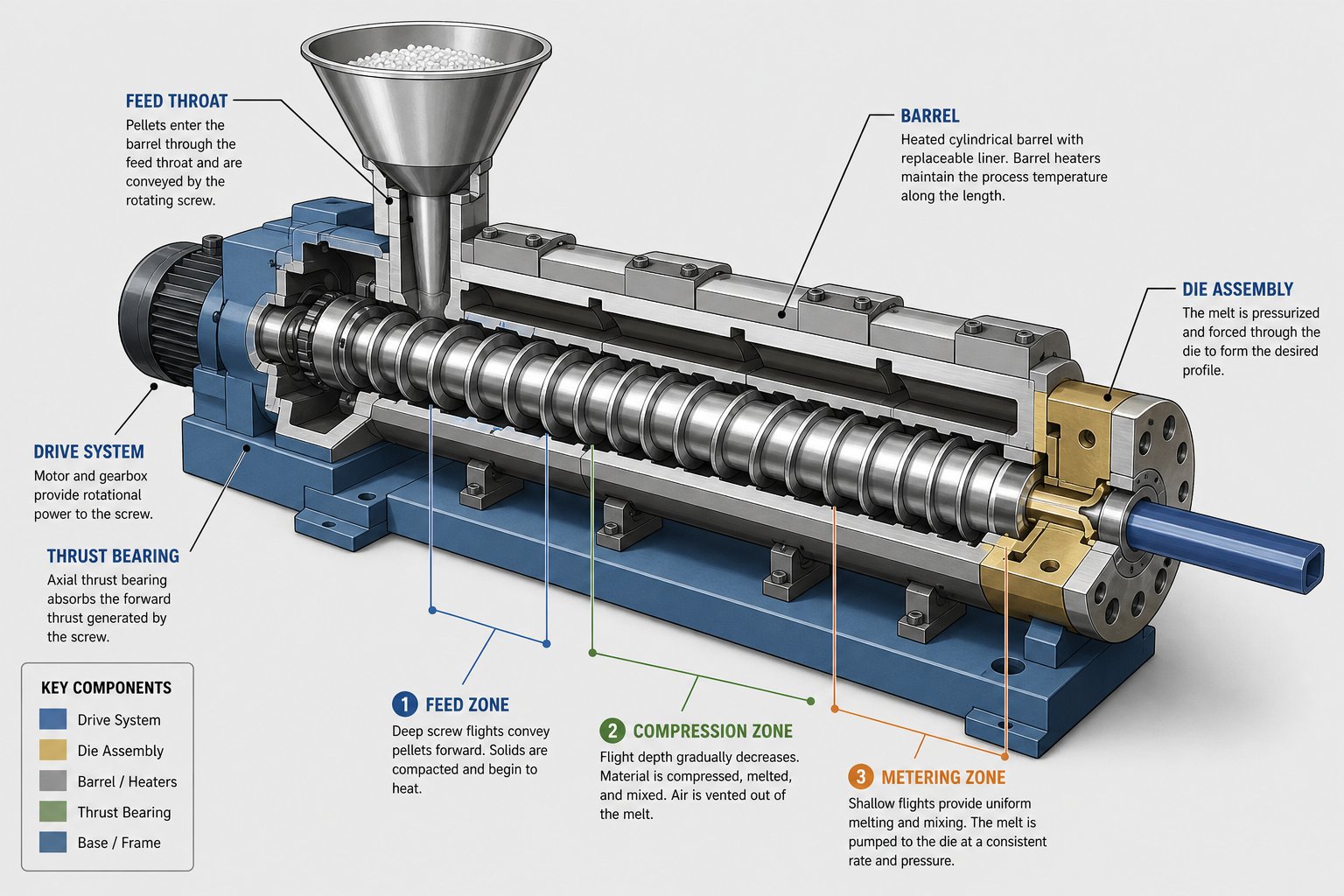
- Hopper Feeding — Pellets, granules, or flakes are loaded into the hopper, often blended with additives such as colorants or UV stabilizers. Gravity (or a force feeder) delivers the material into the feed throat at the rear of the barrel.
- Solids Conveying Zone (Feed Zone) — The rotating screw catches the solid pellets and pushes them forward along the barrel wall. Flight depth is deepest here to accept the maximum volume of unmelted material. Friction between the pellets and the barrel wall is what drives the material forward — not the screw flights alone.
- Compression / Transition Zone — As the screw flights become progressively shallower, the material is compacted. This compression squeezes out trapped air, forces the pellets into tighter contact with the heated barrel wall, and generates significant frictional (shear) heat. The combination of external barrel heaters and internal shear energy begins melting the polymer.
- Metering Zone — By this point, the polymer should be fully molten. The shallow, constant-depth flights in the metering zone create a uniform melt pressure and stabilize the flow rate. Consistent output here is what ultimately determines dimensional accuracy in the finished product.
- Screen Pack and Breaker Plate Filtration — The melt passes through a screen pack supported by a breaker plate. This step filters contaminants, eliminates rotational memory (spiraling flow) induced by the screw, and builds beneficial back pressure that improves mixing quality.
- Die Shaping — The filtered melt enters the extrusion die, which defines the product's cross-sectional geometry — whether that is a round pipe, a flat sheet, a complex window profile, or a thin film bubble. Uniform flow distribution across the die land is critical; even small imbalances show up as wall-thickness variation.
- Cooling and Solidification — The shaped extrudate exits the die and enters a cooling stage — water baths for pipes, chilled rolls for sheets, or air rings for blown film. Because thermoplastics conduct heat poorly, controlled cooling prevents warping, residual stress, and dimensional drift.
Each stage depends on the one before it. Inconsistent feeding starves the compression zone, poor compression leaves unmelted particles in the metering zone, and an unstable melt pressure at the die produces scrap. That interdependence is what makes extrusion plastic processing both elegant and unforgiving.
How Barrel Temperature Zones Control Melt Quality
When you look at an extruder's control panel, you will see multiple temperature set points — typically four to six zones running from the feed throat to the die. These are not arbitrary numbers. Each zone has a distinct thermal role, and getting the profile wrong triggers a cascade of downstream defects.
Here is the logic behind zone-by-zone temperature profiling:
- Feed Zone — Keep it cool. The feed zone is often externally cooled with water jackets. Why? If the barrel wall temperature climbs too high here, pellets soften prematurely, stick together, and bridge across the screw channel. That chokes material flow and starves everything downstream. Typical feed-zone set points for standard thermoplastics stay well below the polymer's softening temperature — often in the range of 20 to 60 degrees Celsius — precisely to prevent this.
- Transition Zone — Ramp it up. The transition (compression) zone is where the real melting work happens. Set temperatures climb above the polymer's softening or crystalline melting point so that barrel heat works together with shear energy to complete the melt. Setting this zone too low forces the screw to do all the work through friction, which spikes motor load and risks overheating localized spots in the melt.
- Metering Zone — Stabilize. The metering zone's job is thermal uniformity. Set temperatures here are typically close to the target processing temperature for the resin. The goal is a homogeneous melt with minimal temperature variation across the flow path — a challenge, since real-world melt temperature can vary by as much as 30 degrees Celsius across the barrel cross-section.
- Die Zone — Match the target. The die temperature usually aligns with the resin manufacturer's recommended processing temperature. Setting it too high risks degradation; too low increases die pressure and can cause surface defects.
Sounds straightforward? Here is where it gets interesting. These zones do not operate in isolation — they interact with every other process variable on the extrusion line.
Consider screw speed. Increasing RPM pushes more material through the barrel faster, which raises shear heat inside the melt. That additional internal energy may require you to lower barrel set points to keep the actual melt temperature on target. The reverse is also true: if you slow the screw down, you lose shear heat and may need to bump zone temperatures up to compensate.
Back pressure follows a similar pattern. Tighter screen packs or a more restrictive die increase the resistance the melt must overcome. Higher resistance means the screw works harder, generating more heat — which again shifts the thermal balance. As veteran extrusion engineer Allan Griff puts it, a colder die temperature raises back pressure, which in turn generates more heat in the screw — making the actual output temperature difficult to predict without experience or simulation (Plastics Today).
Line speed adds yet another layer. Speed up the haul-off, and the extrudate spends less time cooling, which can cause sizing problems downstream. Slow it down, and the product may over-cool and warp before it clears the calibration tank.
The practical takeaway? Never adjust a single parameter in isolation. Every change to screw RPM, barrel temperature, back pressure, or line speed ripples through the entire process. Always reference the resin supplier's material datasheet for recommended melt-temperature ranges — those values are your starting point, not a destination — and fine-tune based on the specific extruder for polymer processing, screw geometry, and downstream conditions you are running.
Mastering these interactions turns an extrusion machine from a temperamental beast into a predictable production tool. Yet even a perfectly tuned process can only perform as well as the hardware behind it — which raises a critical question about the mechanical components that make all of this motion, heat, and pressure possible.
Essential Components Inside Every Plastic Extruder
Heat, pressure, and motion do not appear out of thin air. Every thermal zone, every RPM change, and every gram of throughput discussed so far depends on physical hardware engineered to withstand punishing conditions — high temperatures, abrasive polymers, and sustained mechanical loads running twenty-four hours a day. Understanding what each component actually does, and what separates a well-built part from a cheap one, is the difference between a line that runs reliably and one that bleeds money through downtime and scrap.
Screw, Barrel, and Feed Throat — The Heart of the Extruder
If you strip away the motor, the controls, and the downstream equipment, what remains is the core trio: the extruder screw, the extruder feed barrel, and the feed throat. These three components handle every bit of conveying, compressing, melting, and pressurizing that the process demands.
The screw itself is divided into three functional zones, each with a distinct geometry tailored to a specific job:
- Feed Zone — Deep flights accept the maximum volume of solid pellets and push them forward along the barrel wall. The generous channel depth here ensures bulk material moves efficiently without excessive shear. As NC State Extension research explains, screw channel depth decreases in the order of conveying, compression, and metering — and that sequence is deliberate.
- Compression (Transition) Zone — Flights become progressively shallower, squeezing trapped air out and forcing pellets against the heated barrel wall. The compression ratio — the ratio of feed-zone channel depth to metering-zone channel depth — is one of the most critical design parameters. Too low, and unmelted solids reach the die. Too high, and excessive shear degrades heat-sensitive resins.
- Metering Zone — Constant, shallow flights deliver a homogeneous melt at steady pressure to the die. Consistency here is everything; any variation in pressure or temperature translates directly into dimensional defects in the finished product.
Beyond zone layout, three geometric variables define how well a screw performs: flight depth, pitch (the distance between consecutive flights), and compression ratio. Increasing pitch boosts material conveyance but raises shear input. Decreasing channel depth or width also increases shear — useful for thorough melting, but risky for shear-sensitive polymers. There is no universal screw geometry that works for every material, which is why experienced manufacturers design screws around the specific resin and product being processed.
The barrel surrounding that screw must survive constant abrasion and corrosive chemical attack. Two metallurgy approaches dominate:
- Nitrided steel barrels — A nitrogen-hardened surface layer provides good wear resistance for standard polyolefins and other unfilled resins. Cost-effective, but the hardened layer is relatively thin and wears faster with abrasive compounds.
- Bimetallic-lined barrels — A centrifugally cast alloy liner (often iron-boron or nickel-based) bonds to the barrel's inner bore, offering significantly higher abrasion and corrosion resistance. For glass-filled polymers, mineral-filled compounds, or corrosive PVC, bimetallic liners are effectively mandatory.
The feed throat sits at the junction where the hopper meets the barrel. Its job sounds simple — let pellets in — but poor design here causes bridging, where softened pellets stick together and block the channel. High-quality feed throats feature water-cooling jackets that keep the entry zone well below the polymer's softening point, preventing premature melt and ensuring a steady, uninterrupted flow of solids into the screw.
Extrusion Dies, Screen Changers, and Breaker Plates
The extrusion die is where the molten polymer finally takes shape. Think of it as the mold that defines the product's cross-section — except unlike injection molds, extrusion dies produce continuous output. A pipe die creates an annular opening, a sheet die spreads melt across a wide, flat slot, and a profile die mirrors the exact geometry of a window frame, deck board, or cable channel.
Designing a plastic extruder die is not as straightforward as cutting a hole in the right shape. The melt must flow uniformly across the entire die land; otherwise, one side of a pipe comes out thicker than the other, or the edges of a sheet taper. Die geometry must account for the resin's viscosity — high-viscosity melts need wider flow channels and gentler transitions to avoid excessive pressure drop, while low-viscosity materials require tighter tolerances to prevent drooling or uneven flow.
Then there is die swell. When the pressurized melt exits the die, it relaxes and expands — sometimes by 10 to 30 percent beyond the die opening dimensions. Engineers compensate by making the die opening slightly undersized and using downstream calibration tools to hold the final shape. Ignoring die swell leads to products that are consistently out of spec, regardless of how well the rest of the line performs.
Upstream of the die sit the breaker plate and screen changer — two components that are frequently confused but serve different roles. The breaker plate is a thick, perforated steel disc that supports the wire mesh screen pack under melt pressure, which typically ranges from 100 to 400 bar in standard thermoplastic processing. Without it, the fine screen mesh would rupture within minutes. The breaker plate also disrupts the helical flow pattern imparted by the screw, converting it into a more uniform, linear flow before the melt enters the die.
A screen changer goes further. It includes the breaker plate and screen pack but adds a mechanism — hydraulic slide, piston, or continuous belt — that allows operators to replace or clean the screen pack without a full line stop. On lines processing virgin resin with minimal contamination, a fixed breaker plate assembly may suffice. But on any line running recycled feedstock, filled compounds, or high-throughput production, a screen changer dramatically reduces downtime. Every screen change on a fixed breaker plate requires 30 to 60 minutes of cooling, disassembly, and restart — time that adds up fast across multiple shifts.
Drive System and Gearbox Fundamentals
The motor-gearbox-screw drivetrain is easy to overlook because it sits behind the barrel and rarely gets the attention that screws and extrusion dies receive. Yet it is the component most likely to cause catastrophic unplanned downtime if undersized or poorly maintained.
Here is the chain: an electric motor (typically AC inverter-driven or servo) generates rotational speed. The extruder gearbox steps that speed down while multiplying torque — because screws need high torque at relatively low RPM to push viscous polymer through the barrel and die. A gearbox designed for a plastic extruder machine must handle sustained axial thrust loads created by the screw pushing melt forward, as well as continuous radial loads from the screw's rotation. Undersized gearboxes overheat, leak lubricant, and ultimately fail — often destroying bearings and seals that take days, not hours, to replace.
What separates a reliable drive system from a problematic one? Three factors stand out:
- Torque rating relative to screw demand — The gearbox torque capacity should exceed the maximum process torque requirement with a comfortable safety margin. Running at the edge of the rating accelerates wear on gears and bearings.
- Thrust bearing quality — The thrust bearing absorbs the axial load generated by the screw. Inferior bearings are the most common single point of gearbox failure in extrusion.
- Lubrication and cooling — Gearbox oil degrades under sustained heat. Systems with integrated oil coolers and regular oil analysis schedules outlast those that rely on passive cooling alone.
Together, the screw, barrel, feed throat, die, screen changer, and gearbox form the mechanical backbone of every extruder. The quality of each component directly dictates throughput, product consistency, and maintenance intervals. Yet even perfectly engineered hardware cannot compensate for a mismatched configuration — running a single screw where a twin screw is needed, or vice versa, creates problems that no amount of fine-tuning can fix.
Single Screw vs Twin Screw Extruder Machines Compared
A perfectly built screw, barrel, and gearbox still cannot save a production line if the fundamental extruder configuration is wrong for the job. A single screw extruder machine handles straightforward melting and shaping brilliantly — but hand it a complex compounding recipe, and it struggles. A twin screw extruder machine excels at intensive mixing — but paying for that capability when all you need is basic pipe production wastes capital and complicates maintenance. Choosing correctly here sets the ceiling for everything downstream.
Single Screw Extruders — Versatile Workhorses
The single screw extruder is the most widely deployed configuration in the plastics industry, and for good reason. One rotating screw inside a heated barrel conveys, melts, and pumps polymer forward using drag flow — the friction between the material and the barrel wall does the heavy lifting. It is a mechanically simple, well-understood design that delivers reliable output shift after shift.
You will find single screw extrusion machines dominating pipe production, window profiles, flat sheet, cast and blown film, wire coating, and general-purpose pelletizing. Their sweet spot is any application where the feedstock is a consistent, pre-compounded thermoplastic and the primary goal is melting and shaping rather than intensive blending.
A key specification to watch is the L/D ratio — the barrel length divided by the screw diameter. Most single screw extruders operate in the 24:1 to 36:1 range. A shorter barrel (say, 24:1) works well for heat-sensitive materials that degrade with extended residence time. Longer barrels (30:1 to 36:1) provide more residence time, better melting uniformity, and improved mixing — particularly valuable when processing semi-crystalline polymers or running at higher throughputs. Some modern designs push even further, with specialized recycling platforms reaching L/D ratios above 36:1 for enhanced degassing and homogenization.
The trade-off? Mixing capability. A single screw relies on shear generated between the screw flights and barrel wall, which is adequate for melting uniform pellets but limited when you need to disperse fine powders, distribute color pigments evenly, or blend incompatible polymers. Specialized mixing elements — barrier flights, Maddock mixers, or pin-mixing sections — can improve dispersive mixing, but they cannot fully replicate the intensity a twin screw delivers.
Twin Screw Extruders — Superior Mixing and Compounding
Where a single screw pushes material forward through friction, a twin screw extruder uses two intermeshing screws to physically pump material through the barrel via positive displacement. That fundamental difference changes everything about how the machine handles difficult feedstocks and complex formulations.
Twin screw extruders come in two primary configurations, and mixing them up leads to the wrong purchase:
- Co-rotating intermeshing — Both screws turn in the same direction. The material travels in a figure-eight path between the two screws, generating high shear at the intermeshing zone. This design delivers exceptional distributive and dispersive mixing, making it the standard for compounding, color masterbatch production, glass-fiber reinforcement, reactive extrusion, and devolatilization. The self-wiping action of co-rotating screws prevents material buildup, shortens residence time, and reduces the risk of thermal degradation — a critical advantage for heat-sensitive polymers.
- Counter-rotating intermeshing — The screws turn in opposite directions, creating a calender-like nip zone that generates lower shear but higher pressure. Counter-rotating twins are the go-to choice for PVC pipe and profile extrusion, where gentle melting and precise pressure control matter more than aggressive mixing. PVC's shear sensitivity makes it a poor match for high-shear co-rotating designs.
A double screw extruder also offers modular screw design — operators can rearrange conveying, kneading, and mixing elements along the shaft to fine-tune the screw profile for different recipes without replacing the entire screw. That flexibility is why compounding facilities running dozens of formulations overwhelmingly prefer twin screw extruders over single screw alternatives.
The downsides are real, though. Twin screw machines require heavier-duty gearboxes to handle the complex load distribution across two screws. Precision-machined intermeshing elements drive up manufacturing costs. And operational complexity increases — metered (starve) feeding is typically required, meaning you need gravimetric feeders and more sophisticated process controls. For a facility running one or two straightforward resins into standard profiles, that additional complexity rarely pays for itself.
Choosing Between Single and Twin Screw Configurations
The decision comes down to what your production actually demands. The following comparison lays out the practical differences across the criteria that matter most on the plant floor:
| Criteria | Single Screw Extruder | Twin Screw Extruder |
|---|---|---|
| Typical Applications | Pipe, profile, sheet, film, wire coating, general pelletizing | Compounding, masterbatch, filled polymers, reactive extrusion, recycling of mixed streams, PVC pipe and profile (counter-rotating) |
| Mixing Capability | Basic melting and pumping; limited dispersive mixing without special elements | Excellent distributive and dispersive mixing; modular screw elements allow recipe-specific optimization |
| Material Conveyance | Drag flow (friction-dependent) | Positive displacement (friction-independent) |
| Feedstock Flexibility | Best with uniform pellets; struggles with powders and low-bulk-density materials | Handles pellets, powders, flakes, and inconsistent feedstocks reliably |
| Cost Range | Lower capital investment and tooling costs | Higher upfront cost due to complex gearbox and precision screw manufacturing |
| Maintenance Complexity | Simpler — fewer wear parts, straightforward screw pulls | More complex — two screws, heavier gearbox loads, tighter tolerances on intermeshing elements |
| Degassing / Venting | Limited venting capability | Superior — starve-fed operation enables multiple vacuum vent ports |
| Best For | High-volume, continuous production of standard thermoplastic products from pre-compounded resin | Applications demanding intensive mixing, multi-additive formulations, or variable-quality feedstocks |
A helpful rule of thumb: if your feedstock arrives as clean, consistent pellets and your product has a constant cross-section, a single screw extruder is almost certainly the more cost-effective path. If your process involves blending multiple additives, reinforcing with fibers, processing recycled scrap with variable melt flow, or running reactive chemistry inside the barrel, twin screw extruders earn their premium through superior output consistency and reduced scrap rates.
Keep in mind that the extruder type you select also dictates the materials you can realistically process — and each resin brings its own set of thermal, mechanical, and chemical demands that the screw, barrel, and temperature profile must accommodate.
Which Plastics Can You Extrude and What Each Requires
Every resin behaves differently the moment it hits the screw. Some melt easily with a wide processing window; others degrade within a few degrees of their ideal temperature. Some absorb atmospheric moisture and must be dried before they ever touch the feed throat; others shrug off humidity entirely. Knowing these characteristics before you run a single kilogram determines whether your thermoplastic extruder produces consistent product — or generates a pile of off-spec waste.
Common Thermoplastics and Their Extrusion Characteristics
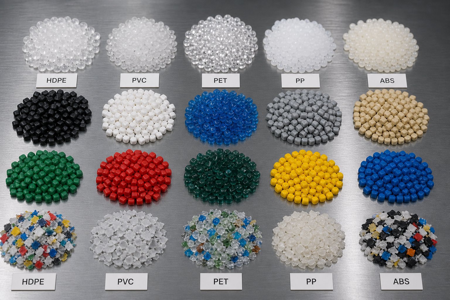
Eight polymers account for the vast majority of extruded products worldwide. The table below summarizes each material's general melt range, moisture sensitivity, shear behavior, and typical end products. Use it as a starting framework, but always confirm exact processing parameters against the resin supplier's datasheet — formulation differences, additives, and molecular weight variations shift these values from grade to grade.
| Material | General Melt Range | Pre-Drying Required | Shear Sensitivity | Common Extruded Products |
|---|---|---|---|---|
| HDPE | 180–230 °C | No | Low | Pipes, bottles, geomembranes, industrial containers |
| LDPE | 160–220 °C | No | Low | Packaging films, squeeze bottles, agricultural film |
| PP | 200–260 °C | No | Low to Moderate | Strapping, sheets, fibers, food containers, automotive trim |
| PVC | 160–200 °C | No | High | Pipes, window profiles, cable insulation, flooring, fittings |
| PET | 250–280 °C | Yes (critical) | Moderate | Sheet, strapping, fibers, thermoforming stock |
| ABS | 210–260 °C | Yes | Moderate | Profiles, sheet, edge banding, appliance housings |
| PS | 180–240 °C | No | Low | Foam sheet, food packaging, insulation board |
| Nylon (PA) | 240–290 °C | Yes (critical) | Moderate | Tubing, monofilament, engineering profiles, cable ties |
A few entries deserve extra attention. PVC stands out because of its extreme shear sensitivity — excessive screw speed or an aggressive compression ratio generates enough frictional heat to trigger thermal degradation, releasing hydrochloric acid that corrodes the barrel and screw. That is why a dedicated pvc extruder machine almost always uses a counter-rotating twin screw design or a specially profiled single screw with a low compression ratio to keep shear forces in check. Running PVC on general-purpose equipment designed for polyolefins is one of the fastest ways to destroy both the product and the hardware.
PET sits at the other end of the spectrum — not because of shear, but because of moisture. PET is hygroscopic, meaning it absorbs water from the air. If that moisture is not removed through thorough desiccant drying before extrusion, hydrolysis breaks down the polymer chains during melting, resulting in hazy, brittle output with severely reduced mechanical properties. A pet extrusion machine line without a properly sized dryer upstream is essentially a scrap generator. Nylon and ABS share this hygroscopic behavior, though PET is the most punishing of the three.
Processing Recycled vs Virgin Feedstocks
Recycled plastics — rPET flakes, rHDPE regrind, rPP regranulate — arrive at your feed hopper carrying three problems that virgin pellets do not:
- Inconsistent melt flow index (MFI) — Recycled batches blend material from multiple sources with different molecular weights. One batch may flow freely; the next may resist melting. That fluctuation destabilizes output rates and dimensional tolerances.
- Higher moisture and volatile content — Post-consumer streams carry residual product contamination, washing water, and adhesive volatiles. Without aggressive drying and venting, these volatiles become bubbles, voids, and surface defects in the finished extrudate.
- Abrasive contamination — Sand, glass fragments, metal fines, paper char, and traces of incompatible polymers ride along with the recycled feedstock. These abrasive contaminants grind against screw flights and barrel bore continuously, accelerating wear far beyond what virgin resin causes.
These challenges do not mean recycled material is impractical — far from it. They mean a plastic recycling extruder demands different hardware choices. A recycled plastic extruder typically requires deeper feed channels to handle the lower bulk density of flake and regrind. Higher compression ratios help compensate for inconsistent melt behavior. Screen changers become essential rather than optional, filtering solid contaminants before they reach the die. And wear-resistant barrel linings — bimetallic rather than standard nitrided — pay for themselves many times over by extending service life against abrasive feedstock.
For operations running a waste plastic extrusion machine on post-consumer streams, venting is equally important. A vented two-stage screw removes trapped moisture and volatiles mid-barrel, preventing the defects that would otherwise make the final product unsellable. As recycled-content mandates grow across packaging and construction markets, getting these specifications right is increasingly what separates a profitable recycling line from a maintenance headache.
Matching Material to Screw Geometry
Every material property discussed above — melt viscosity, shear sensitivity, moisture content, crystallinity — feeds directly back into one design decision: screw geometry. The screw compression ratio (the depth of the feed channel divided by the depth of the metering channel) and flight depth must be tailored to the specific polymer being processed.
Consider the contrast between a pvc extruder screw and one built for HDPE. PVC's extreme shear sensitivity calls for a low compression ratio — typically in the range of 1.6:1 to 2:1 — to limit frictional heat generation. A pvc extrusion machine screw also benefits from shorter L/D ratios to reduce residence time, since prolonged heat exposure degrades the material. HDPE, by contrast, tolerates higher shear and benefits from a more aggressive compression ratio (around 3:1 to 4:1) that ensures complete melting of its semi-crystalline structure.
Hygroscopic resins like PET and nylon add another layer. These polymers often run on vented screws with a two-stage design — a first stage that melts the material, a decompression zone where a vacuum vent extracts moisture and volatiles, and a second stage that re-pressurizes the melt for the die. The additional barrel length required for venting pushes the L/D ratio higher, which is why a pet extrusion machine typically runs at 30:1 or above.
The takeaway is straightforward: there is no universal screw. A geometry optimized for polyolefins will underperform on PVC and may ruin PET. Before specifying any plastic extruder machine, define your material first — its melt behavior, moisture requirements, and shear limits will dictate the screw design, barrel metallurgy, and upstream drying equipment your line needs. Get the material-to-hardware match right, and the rest of the line falls into place. Get it wrong, and no amount of downstream adjustment compensates.
Of course, the extruder itself is only one piece of a much larger production system. The equipment that sits before and after it — dryers, feeders, cooling tanks, haul-offs, cutters — determines whether that perfectly matched screw and barrel actually deliver a sellable product at the end of the line.
Building a Complete Extrusion Line Beyond the Extruder
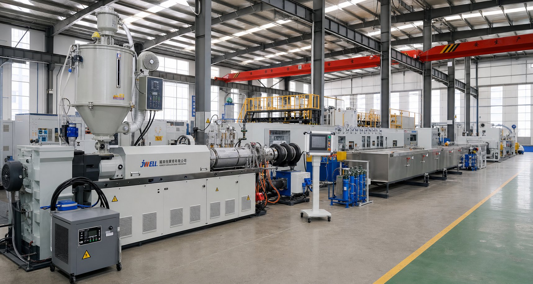
A perfectly specified extruder with the ideal screw geometry and barrel metallurgy is still just one station in a much longer production chain. The equipment flanking it — everything from the dryer feeding pellets upstream to the saw cutting finished profiles downstream — determines whether your plastic extrusion line actually delivers sellable product or generates dimensional drift, surface defects, and waste. As Conair's extrusion processing guide puts it plainly: without auxiliary equipment, extruders alone could not produce anything.
Upstream Equipment — Drying, Feeding, and Dosing Systems
Before a single pellet enters the feed throat, upstream equipment has already shaped the outcome. Imagine feeding your extruder a blend that is five percent off on colorant concentration, or pellets carrying 0.1 percent residual moisture when the resin demands below 0.005 percent. The screw and barrel cannot fix those problems — they simply pass them through to the finished product as color streaks, voids, or brittle sections.
Three categories of upstream equipment prevent that:
- Hopper dryers and dehumidifiers — Essential for hygroscopic resins like PET, nylon, and ABS. Desiccant dryers circulate hot, ultra-dry air through the material hopper, reducing moisture to safe processing levels. Consistent drying also homogenizes pellet temperature, eliminating seasonal swings caused by cold winter silos or hot summer storage — a subtle but real source of melt inconsistency.
- Gravimetric and volumetric feeders — Volumetric feeders dispense material by volume at a set screw speed — simple and inexpensive, but blind to density changes in regrind or recycled flakes. Gravimetric feeders weigh each ingredient in real time, adjusting feed rates to maintain a precise recipe by mass. For any line where additive ratios directly affect product performance — UV stabilizers in agricultural film, flame retardants in cable compounds — gravimetric dosing pays for itself quickly through reduced scrap and consistent quality.
- Material blending stations — Blenders combine virgin pellets, recycled regrind, colorant, and additives into a uniform mixture before feeding the extruder. Digitally controlled recipes ensure repeatability shift after shift. Film extrusion lines face a particular challenge here: lightweight edge-trim regrind does not mix uniformly with denser virgin pellets in a standard blender, so specialized high-regrind blending systems are often required.
The core principle is simple: inconsistent input equals inconsistent output. If feeding varies by even a few percent, dimensional tolerances and surface quality suffer downstream — and no amount of barrel temperature adjustment can compensate.
Downstream Equipment That Completes the Production Line
Downstream processing begins the instant hot extrudate exits the die. From that point forward, a sequence of equipment stations shapes, cools, measures, pulls, cuts, and collects the product — and every station must run in precise coordination with the extruder's output rate. Here is the typical downstream flow:
- Calibration and sizing tools — These specialized fixtures accept the hot, soft extrudate and guide it into its target dimensions. For pipe, a vacuum calibration sleeve pulls the still-soft wall against a precision bore. For profiles, a series of dry or wet calibrators progressively refine the cross-section.
- Cooling tanks (vacuum or spray) — Heat must be removed at a controlled rate so the polymer solidifies without warping. Smaller products like tubing use immersion tanks, often under vacuum to maintain internal dimensions. Larger extrusions such as pipe and decking rely on spray-cooling tanks where temperature-controlled water jets provide uniform heat extraction. Temperature control units regulate coolant temperature to prevent the gradual drift that causes slow dimensional creep.
- Haul-off (puller) units — Motorized belt or caterpillar pullers grip the cooled extrudate and draw it through the entire downstream train at a precise, adjustable speed. This is the single most critical synchronization point on the line: if puller speed does not match screw output, wall thickness changes immediately. As the pipe extrusion process overview from On Line Controls explains, changes in puller speed and grip behavior directly affect wall thickness and dimensional stability.
- Cutting systems — Depending on the product, cutting may involve traveling planetary saws for thick-walled pipe, high-speed guillotine cutters for profiles, or rotary knife cutters for flexible tubing. Many operate on moving tables synchronized to line speed so the cut happens without stopping or deforming the extrudate.
- Stacking, winding, or coiling equipment — Cut-to-length products are collected on automatic stackers or unloaders. Flexible tubing and small-diameter pipe are wound onto coils. Film is rolled onto winding stations with tension control to prevent wrinkles and telescoping.
- Inline printing or marking — Product identification, meter marks, lot codes, and regulatory information are printed or embossed onto the extrudate surface while it moves through the line, eliminating the need for secondary operations.
Every element in this chain feeds data back to the master extrusion control. Inline measurement systems monitor OD, wall thickness, and ovality in real time, feeding corrections to screw speed and puller speed automatically. That closed-loop feedback is what keeps a plastic pipe extrusion machine holding tolerances over an eight-hour run instead of drifting out of spec within the first thirty minutes.
Application-Specific Line Configurations
A pipe line and a blown film line share the same extruder concept, but their downstream equipment looks nothing alike. The die geometry, cooling method, and collection systems are all dictated by the final product's shape and material. The table below maps four common applications to their line-specific configurations:
| Application | Die Type | Cooling Method | Key Downstream Equipment |
|---|---|---|---|
| Pipe Extrusion | Annular (spider or spiral mandrel) die | Vacuum sizing + spray or immersion cooling tanks | Vacuum calibrator, spray tanks, haul-off, planetary saw, automatic stacker or coiler |
| Blown Film | Annular blown film die with air ring | External air cooling via air ring; internal bubble cooling (IBC) on high-output lines | Collapsing frame, nip rolls, corona treater, winder with tension control, edge-trim granulator |
| Sheet Extrusion (e.g., PP Sheet Extrusion Line) | Flat slot (coat-hanger) die | Three-roll polishing/cooling stack (chill rolls) | Chill roll stack, thickness gauge, edge trimmer, cross cutter or winder, sheet stacker |
| WPC Profile Extrusion | Profile die matched to decking or board geometry | Spray cooling with extended cooling sections | Dry calibrators, spray tanks, embossing unit, haul-off, traveling cut-off saw, automated stacker |
Notice how each application demands entirely different downstream hardware. A pipe extrusion machine line needs vacuum calibration to hold roundness while the polymer is still soft — a requirement that does not exist on a blown film machine line, where an air ring and collapsing frame manage the bubble instead. A pp sheet extrusion line relies on a chill roll stack to polish and cool flat sheet simultaneously, while a WPC line requires extended spray sections because wood-filled composites conduct heat poorly and take significantly longer to solidify.
The lesson is practical: specifying an extruder without designing the full upstream and downstream system around it is like buying an engine without building the car. Material handling, drying, feeding, calibration, cooling, pulling, cutting, and collection must all be engineered as an integrated system — and each application demands its own configuration. Getting these supporting stations right is what separates a production line that holds tolerance hour after hour from one that requires constant operator intervention.
Yet even a well-configured line still demands evaluation against hard numbers — throughput capacity, energy draw, motor ratings, and total cost of ownership — before signing a purchase order.
Key Technical Specifications and Cost Factors to Evaluate
A well-configured extrusion line with the right upstream dryers, downstream cooling tanks, and synchronized haul-offs still underperforms if the extruder at its center is undersized, over-powered, or mismatched to the production target. Specifications printed on a datasheet — L/D ratio, screw diameter, motor rating, RPM range — are not abstract numbers. Each one directly controls throughput, melt quality, energy draw, and ultimately the plastic extrusion cost per kilogram of finished product. Understanding what these numbers mean in practice is what separates a confident purchase decision from an expensive guess.
Critical Specifications — L/D Ratio, Screw Diameter, and Throughput
Three specifications define the core capability of any extruder. Get these right, and everything else — temperature control, die performance, downstream synchronization — falls within a workable range. Get them wrong, and you are fighting the machine every shift.
L/D Ratio. The length-to-diameter ratio tells you how much barrel length the material travels relative to the screw's diameter. A higher L/D ratio means more residence time inside the barrel, which translates into more thorough melting, better mixing, and additional opportunities for degassing. As research on screw geometry confirms, excessively long screws can cause thermal degradation of sensitive materials or energy inefficiencies — so bigger is not automatically better. Most single screw extruders operate between 24:1 and 36:1. Twin screw compounding lines often push higher, into the 40:1 to 48:1 range, because modular screw elements need room for multiple kneading and venting sections. For heat-sensitive resins like PVC, shorter barrels limit thermal exposure. For semi-crystalline polymers or recycled feedstocks that benefit from extended mixing, longer barrels pay dividends in output consistency.
Screw Diameter. Diameter is the primary lever for throughput capacity. A larger screw moves more material per revolution — the relationship is roughly proportional to the cube of the diameter, meaning a jump from 60 mm to 90 mm does not increase output by 50 percent; it can nearly triple it. Smaller diameters (20–45 mm) suit lab-scale trials, pilot runs, and low-volume specialty products. Mid-range diameters (50–90 mm) cover the bulk of commercial pipe, profile, and sheet production. Large-bore machines (100–150 mm and above) serve high-volume film, pipe, and recycling operations where throughput targets reach hundreds or thousands of kilograms per hour. The screw diameter also influences shear rate — a smaller diameter produces higher shear at the same RPM, which matters when processing shear-sensitive polymers.
RPM Range and Motor Power. Screw speed determines how fast material moves through the barrel and how much shear heat is generated internally. Higher RPM raises throughput but also increases melt temperature, which may push heat-sensitive polymers toward degradation. Motor power rating must deliver enough torque at the operating RPM to overcome the resistance of the polymer and die — and torque, not raw kilowatt rating, is the number that matters. A 75 kW motor driving through a high-reduction gearbox delivers far more usable torque at low screw speeds than the same motor coupled to a low-reduction gearbox spinning faster. Always check the torque curve, not just the nameplate power. For specific throughput benchmarks tied to your resin and product geometry, request OEM specification sheets — published figures vary significantly by manufacturer and configuration.
Energy Consumption and Production Cost Variables
Energy is the second-largest operating cost on most extrusion lines, trailing only raw material. Yet many buyers fixate on plastic extruder machine price at purchase and ignore the running costs that accumulate over years of production. Three technology choices embedded in the machine's design determine how much power it consumes shift after shift.
Motor efficiency class. International efficiency ratings — IE3 (premium) and IE4 (super premium) — indicate how much electrical energy the motor converts into mechanical work versus waste heat. Upgrading from a standard IE2 motor to an IE4 unit on a 75 kW extruder drive can save thousands of kilowatt-hours annually. Field audit data shows that an oversized motor running below 50 percent load loses 4 to 8 percentage points of efficiency compared to a properly sized unit — a hidden drain that quietly inflates the extruder machine price you pay in electricity every month.
Barrel heating technology. Mica band heaters are the cheapest option but radiate significant heat into the factory environment. Ceramic band heaters reduce radiated losses by 10 to 12 percent on heating zones, while induction heating systems offer the fastest response times and tightest temperature control — at a higher capital cost. Barrel insulation jackets are the simplest retrofit available: wrapping exposed barrel zones with removable thermal blankets cuts total line energy consumption by 3 to 5 percent, often paying for themselves in under six months.
Drive type. AC inverter drives (variable frequency drives, or VFDs) allow the motor to run at precisely the speed the process demands rather than at a fixed speed with mechanical throttling. Servo drives take efficiency a step further, eliminating slip losses entirely. Retrofit audit data from production lines shows VFD installations delivering 8 to 15 percent energy savings compared to direct-on-line motor operation.
Energy, however, is only one slice of the total plastic extrusion machine cost equation. A complete cost picture includes five variables:
- Material cost — Typically 60 to 75 percent of total production cost. Resin price fluctuations dwarf all other line items.
- Energy cost — Ranges from roughly 0.18 to 0.55 kWh per kilogram of output depending on line type, polymer, and equipment condition.
- Labor — Operator headcount per shift, skill level, and degree of automation all affect per-kilogram cost.
- Tooling wear — Screw and barrel replacement, die refurbishment, and screen pack consumption are recurring expenses that scale with abrasiveness of the feedstock.
- Scrap rate — Every kilogram of off-spec product carries the full cost of material, energy, and labor with zero revenue return. Reducing scrap from 5 percent to 2 percent on a high-volume line often saves more money than any single equipment upgrade.
When comparing a pvc extrusion machine price against an HDPE pipe line, these variables shift dramatically. PVC runs at lower melt temperatures (consuming less energy per kilogram) but demands specialized corrosion-resistant barrels and gentle screw geometries that increase tooling costs. HDPE tolerates aggressive processing but consumes more thermal energy. Evaluating plastic extrusion cost on a per-kilogram, per-product basis — rather than sticker price alone — reveals the true economics of each configuration.
ROI Considerations for New vs Used Equipment
Browse any industrial marketplace and you will find a plastic extruder machine for sale at a fraction of new-equipment pricing. The temptation is understandable — a used 90 mm single screw line listed at 40 percent of original cost looks like an immediate win on the balance sheet. But the purchase price is where the comparison starts, not where it ends.
Used equipment carries trade-offs that do not appear on the listing page. A plastic extrusion machine for sale on the secondary market may have worn screw flights with excessive clearance, degraded barrel linings, aging heaters with inconsistent zone control, and a gearbox approaching its service limit. Each of these conditions increases energy consumption, raises scrap rates, and shortens the interval before a costly rebuild becomes unavoidable.
Before committing to new or used machinery, evaluate these factors:
- Screw and barrel condition — Request bore measurements and screw flight diameter readings. Clearance beyond manufacturer specifications signals immediate replacement cost.
- Motor and drive technology — Older machines often run IE1 or IE2 motors without VFDs, meaning higher energy costs from day one.
- Control system age — Obsolete PLCs and HMIs may lack spare parts availability, making future repairs difficult or impossible.
- Warranty and support — New equipment typically includes manufacturer warranty, commissioning support, and spare parts guarantees. Used machines rarely offer any of these.
- Compliance and safety — Electrical standards, guarding requirements, and safety certifications evolve. A machine built fifteen years ago may require significant retrofitting to meet current plant safety codes.
- Total cost of ownership over five years — Model the combined purchase price, estimated maintenance, energy consumption, and expected scrap rate. In many cases, a new extruder machine for sale at a higher sticker price delivers a lower five-year total cost because of reduced energy draw, lower maintenance burden, and tighter process control.
The decision is rarely black and white. A well-maintained, recently rebuilt used machine with documented service history and updated controls can be excellent value. A cheap, neglected unit with unknown provenance almost never is. Due diligence on mechanical condition and total cost of ownership — not listing price alone — separates a smart acquisition from a liability disguised as a bargain.
Of course, even the best-specified, brand-new extruder eventually wears. Screws lose flight depth, barrels develop clearance, and heaters degrade — all of which erode the performance gains you paid for at purchase. Knowing when that wear crosses the line from acceptable to costly, and how to address it before it disrupts production, is what keeps a line running profitably year after year.
Screw Barrel Maintenance and When to Replace Worn Components
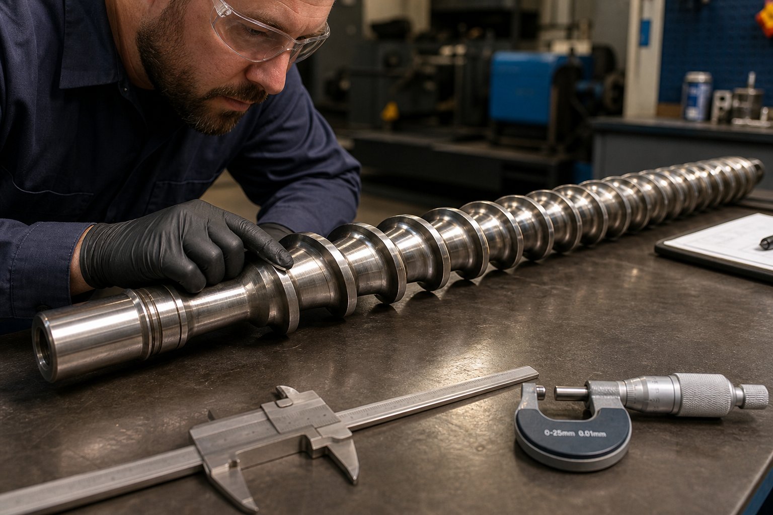
Wear does not announce itself with a sudden failure. It creeps in — a fraction of a millimeter at a time — until the day your operator bumps screw speed to hit rate targets and the discharge temperature spikes beyond what the downstream process can tolerate. At that point, the extrusion screw and barrel have already been costing you money for weeks or months through reduced efficiency, higher energy draw, and thinning profit margins. Recognizing the warning signs early, sourcing the right replacement components, and following a disciplined maintenance schedule are what keep a plastic extruder machine productive instead of bleeding value quietly.
Signs Your Screw and Barrel Need Replacement
Extruder screws and barrels wear gradually, so the symptoms start small and escalate. You might not notice a problem until output has already dropped significantly. Here are the telltale indicators that clearance between the screw flights and barrel wall has grown beyond acceptable limits:
- Declining output at the same RPM — The most reliable early signal. When the flight clearance widens, polymer leaks backward over the flights instead of moving forward. To maintain the same throughput, the operator increases screw speed — a compensating move that masks the underlying problem. Industry data on a 100 mm screw running PE at 150 kg/hr shows that wear-induced clearance growth forced a rate reduction of roughly 13 percent to keep discharge temperature within the acceptable processing window.
- Rising discharge temperature — As the flight clearance increases, the thin film of polymer on the barrel wall thickens, reducing heat-transfer efficiency. Higher screw speeds compound the problem by adding shear heat. The result is a melt that runs hotter than the barrel set points predict.
- Increased energy consumption — A worn single extruder screw demands more motor power to push the same volume of material because back-leakage forces the drive to work harder. If your kWh-per-kilogram metric is trending upward with no process change, wear is a likely culprit.
- Inconsistent melt temperature and pressure fluctuations — Growing clearance disrupts the uniform pumping action of the metering zone. Melt pressure at the die begins to oscillate, which translates directly into wall-thickness variation, surface defects, and dimensional drift in the finished product.
- Visible wear marks or scoring on screw flights — When the screw is pulled for inspection, look for shiny, flattened flight tips where the hard facing has worn away, scoring along the flight lands, or pitting on the screw root caused by corrosive polymers. Corrosive resins like PVC, acetals, and fluoropolymers can produce acid attack that pits metal surfaces well before abrasive wear becomes visible.
- Growing clearance between screw OD and barrel ID — The definitive measurement. A common industry guideline is that the flight clearance for a new plastic extrusion screw should be approximately the nominal screw diameter divided by 1,000, per side. When measured clearance reaches two to four times that original value — depending on application criticality — replacement is warranted.
The decision to replace should ultimately be economic, not arbitrary. Non-critical applications like corrugated pipe can tolerate higher wear levels, while precision-critical processes like medical tubing demand replacement at far tighter thresholds. As extrusion experts Mark Spalding and Tim Womer note, the best decision is to change the screw when the economics of the process warrant the cost of a new or refurbished component — not simply when a rule-of-thumb clearance multiplier is exceeded.
Choosing the Right Replacement Screw Barrel for Your Application
Replacing a worn extrusion screw with an identical copy is the default — but it is not always the best move. The replacement is an opportunity to upgrade metallurgy, coatings, and geometry to better match the material you are actually processing, especially if your feedstock has changed since the original screw was specified.
Barrel metallurgy is the first decision point. Three tiers cover the range of processing demands:
- Nitrided steel — The entry-level option. A nitrogen-hardened surface layer provides adequate wear life for unfilled polyolefins and other non-abrasive resins. Cost-effective, but the hardened layer is thin and wears quickly under abrasive conditions.
- Bimetallic-lined barrels — A centrifugally cast alloy liner (iron-boron or nickel-based) offers significantly higher abrasion and corrosion resistance. This is the standard for processing glass-filled compounds, mineral-loaded formulations, and recycled streams with contaminants. Wear-resistant bimetallic barrels may cost three to four times more than standard nitrided versions, but they provide substantially longer service intervals that justify the premium.
- Tungsten carbide lined or HIP (hot isostatic pressing) barrels — The highest tier, reserved for severely abrasive glass-fiber-reinforced compounds or highly corrosive fluoropolymers. HIP barrels use a nickel-rich boron alloy layer that resists even hydrofluoric acid attack — a level of protection standard metallurgies cannot match.
Screw coatings and hard facings follow similar logic. Cobalt-based or nickel-chrome-boron alloy hard facings on the flight tips protect against abrasive wear. For corrosive resins, full-body chromium carbide coatings or screws manufactured from corrosion-resistant tool steels provide protection that flight-tip-only hard facing cannot. Matching the screw and barrel materials is also critical — differences in coefficient of thermal expansion between the two components can cause binding at high processing temperatures, leading to catastrophic scoring and seizure.
Beyond metallurgy, custom screw designs tailored to specific applications — pipe, profile, film, sheet, WPC, or granulation lines — optimize flight geometry, compression ratio, and mixing elements for the target resin and product. For extrusion manufacturers, recycling plants, and processing teams sourcing application-matched replacement extruder screws and barrels, NANHAIYA's screw barrel support page provides practical component guidance across these application categories, including custom screw barrel configurations for pipe, profile, film, sheet, WPC, and granulation equipment.
One important limit on refurbishment: a screw should generally not be rebuilt more than three times. Each weld pass to reapply hard facing deteriorates the base metal, increasing the risk of delamination between the hard facing and the screw body. After three rebuilds, a new screw is both safer and more cost-effective.
Preventive Maintenance Schedule for Extruder Wear Parts
Reactive maintenance — waiting for symptoms to become obvious before acting — is the most expensive approach. A structured preventive maintenance program catches wear before it erodes profitability and allows downtime to be scheduled during planned production breaks rather than forced by failure.
Here is a practical maintenance cadence for the critical wear components of any plastic extruder machine:
- Regular screw pull inspections — Pull the screw while still hot (to prevent polymer from hardening on the surface), clean it thoroughly with a wire brush and copper gauze, and measure flight OD at multiple points along the screw length using a flight micrometer. Compare readings against the original new-screw dimensions. Frequency depends on material abrasiveness — every 2,000 to 4,000 operating hours for unfilled polymers, more frequently for glass-filled or recycled feedstocks.
- Barrel bore diameter measurement — After purging and pulling the screw, insert an electronic bore gauge into the barrel and record ID readings at every inch mark along the full length. This data reveals localized wear patterns — especially at the end of the melting section and in front of mixing elements, where solids wedging creates high side forces that push the screw into the barrel wall. An iron-based bimetallic barrel liner typically lasts for roughly three screw service lives, but only if wear is monitored and barrel alignment is maintained.
- Heating element and thermocouple checks — Faulty barrel heaters create uneven thermal expansion, which can warp the barrel and accelerate wear. Inspect heater band contact surfaces, measure resistance across each zone, and verify thermocouple accuracy against a calibrated reference. Replace any heater showing signs of intermittent operation or hot spots.
- Gearbox oil analysis and inspection — Extruder gearbox repair is one of the most disruptive and expensive maintenance events on a production line. Regular oil sampling detects metallic particle contamination, viscosity breakdown, and moisture ingress long before bearing failure occurs. Check oil levels, inspect seals for leakage, and monitor operating temperature. If the gearbox runs consistently above its rated temperature, investigate cooling system performance and load conditions before bearing damage escalates.
- Barrel alignment verification — Misalignment between barrel sections accelerates screw wear by forcing the screw against the barrel wall. Verify alignment whenever a barrel is removed or replaced, if the foundation shifts, or if front barrel supports show signs of movement. Contact points on front supports should be lubricated with high-temperature silicone grease or fitted with brazed brass tips to allow smooth thermal expansion.
Keep a spare extrusion screw in storage so that when the working screw reaches its service limit, the swap happens quickly — hours, not days. Send the worn screw for measurement, evaluation, and refurbishment (if within the three-rebuild limit) while production continues uninterrupted.
Tracking these measurements over time transforms maintenance from guesswork into prediction. You will know — not guess — when the next screw change is due, how many operating hours remain on the barrel liner, and whether the gearbox needs service before the next planned shutdown. That predictability is what keeps production costs stable and prevents the kind of emergency downtime that turns a profitable line into a cash drain.
With wear components under control and a clear maintenance rhythm in place, the final question shifts from keeping the line running to choosing the right configuration in the first place — matching extruder type, screw design, and supplier support to your specific application and production goals.
How to Choose the Right Plastic Extruder for Your Operation
Maintenance discipline keeps a line profitable, but it cannot rescue a machine that was wrong for the job from day one. A counter-rotating twin screw purchased for HDPE pipe production wastes capital. A short-barreled single screw assigned to compound glass-filled nylon generates nothing but frustration and scrap. Every material property, screw geometry principle, component specification, and cost variable covered in this article converges on one practical decision: which extruder configuration, screw design, and supply chain support match your specific application?
Matching Your Application to the Right Extruder Type
Rather than re-reading eight sections and cross-referencing mentally, use the table below as a consolidated decision matrix. It maps the most common extrusion applications directly to the recommended extruder type, the screw design features that matter most, and the key downstream equipment each line requires.
| Application | Recommended Extruder Type | Typical Screw Design Features | Key Downstream Equipment |
|---|---|---|---|
| Pipe (HDPE, PP, PVC) | Single screw (polyolefins); counter-rotating twin screw (PVC) | Barrier screw with Maddock mixer for polyolefins; low-compression, gentle-shear geometry for PVC | Vacuum calibration sleeve, spray cooling tanks, haul-off, planetary saw, stacker or coiler |
| Profile (window frames, cable channels) | Single screw (general profiles); counter-rotating twin screw (PVC profiles) | Profile-specific compression ratio; mixing section for color consistency | Dry and wet calibrators, spray tanks, caterpillar haul-off, traveling saw, stacker |
| Blown Film | Single screw (mono-layer); co-extrusion with multiple single screws (multi-layer) | Barrier screw with high L/D (30:1+); grooved feed for HDPE film | Air ring, collapsing frame, nip rolls, corona treater, winder, edge-trim granulator |
| Sheet | Single screw; tandem single screw for foam sheet | Metering-type screw with mixing element; vented design for hygroscopic resins | Coat-hanger die, three-roll polishing stack, thickness gauge, cross cutter or winder |
| WPC (Wood-Plastic Composite) | Counter-rotating twin screw or conical twin screw | Deep-flighted feed zone for low-bulk-density wood fiber; venting for moisture removal | Profile die, dry calibrators, extended spray cooling, embossing unit, haul-off, cut-off saw |
| Granulation / Compounding | Co-rotating twin screw | Modular screw elements — conveying, kneading, and mixing blocks arranged per recipe | Strand die or underwater pelletizer, water bath, air knife, pellet classifier |
| Wire and Cable Coating | Single screw with crosshead die | High-output metering screw; precise melt pressure control for uniform wall thickness | Crosshead die, water trough, capstan, spark tester, take-up reel |
| Tubing (medical, industrial) | Single screw (standard); co-extrusion for multi-lumen tubing | Precision metering zone; low-compression ratio for shear-sensitive medical polymers | Vacuum sizing, water bath, laser micrometer, belt puller, rotary cutter, coiler |
| Recycling (rPET, rHDPE, rPP) | Single screw with vented two-stage design; co-rotating twin screw for mixed streams | Deep feed channel for low-bulk-density flakes; high compression ratio; venting zone | Screen changer, strand pelletizer or underwater pelletizer, dewatering screen, silo |
Scan the application column first. If your product falls clearly into one row, the extruder type and screw features listed there represent the proven starting configuration — not the only option, but the one with the broadest track record across plastic extrusion machines in commercial production. A tubing extruder for medical applications, for example, demands tighter tolerances and gentler screw profiles than a general-purpose pipe line, even though both produce cylindrical products. Context matters as much as geometry.
Evaluating Extruder Manufacturers and Component Suppliers
Selecting the right machine configuration is half the challenge. The other half is finding a supplier — whether an OEM building the full line or a component partner providing replacement screw barrels, dies, and wear parts — that can actually support your application over the long term. Plastic extruder machine manufacturers vary enormously in depth of expertise, and the cheapest quote rarely delivers the lowest total cost.
When evaluating plastic extruder manufacturers or component suppliers, put these criteria on your scorecard:
- Application engineering support — Can the supplier recommend screw geometry, barrel metallurgy, and die configuration based on your specific resin and product? A partner who asks detailed questions about your material, throughput target, and tolerance requirements before quoting is far more valuable than one who sends a price list.
- Custom screw design capability — Off-the-shelf screws work for standard applications, but pipe, film, WPC, and recycling lines each demand tailored compression ratios, flight depths, and mixing elements. Suppliers with in-house screw design and manufacturing handle these requirements without outsourcing delays.
- Material and process expertise — Does the supplier understand the difference between specifying a barrel for unfilled polyolefins versus glass-filled nylon? Metallurgy mismatches — a nitrided barrel running abrasive compounds, for example — lead to premature failure and unplanned downtime.
- Spare parts availability and lead times — A blown heater or a worn screw should not ground your line for weeks. Suppliers who stock common wear parts or maintain short manufacturing lead times minimize production losses.
- After-sales service — Commissioning support, troubleshooting guidance, screw pull measurement assistance, and refurbishment services all contribute to long-term uptime. Evaluate what happens after the purchase order, not just before it.
- Range of supported applications — Suppliers who serve multiple extrusion segments — pipe, profile, film, sheet, WPC, granulation, and recycling — tend to have broader cross-application knowledge. That breadth helps when your product mix evolves.
As a practical example, NANHAIYA serves extrusion manufacturers, recycling plants, and processing teams across pipe, profile, film, sheet, WPC, and granulation applications with replacement screw barrels and custom component guidance — the kind of application-specific support that keeps a plastic extruder for sale listing from becoming a regrettable purchase. Whether you are sourcing a complete line from plastic extrusion machine manufacturers or replacing worn components on existing equipment, the evaluation criteria above apply equally.
Next Steps — From Selection to Production
With the decision framework in hand, resist the temptation to jump straight to a purchase order. A methodical approach prevents costly mismatches and shortens the path to stable production:
- Define your material and product requirements first. Pin down the resin (or resins) you will run, the target product dimensions and tolerances, your throughput goals, and any regulatory or quality standards the finished product must meet. These inputs drive every downstream specification — screw geometry, barrel metallurgy, die design, and cooling setup.
- Request screw barrel samples or consultations from qualified suppliers. Share your material datasheets, production targets, and any known challenges (recycled feedstock variability, abrasive fillers, tight tolerance demands) with two or three extruder manufacturers or component partners. Compare not just pricing, but the depth of their technical recommendations.
- Pilot-test before committing to full production runs. If possible, trial the proposed screw and barrel configuration on a test line or request sample output from the supplier's facility. A pilot run reveals melt quality, throughput stability, and dimensional consistency under real conditions — data that a specification sheet alone cannot provide.
- Plan for wear from the start. Order a spare extrusion screw alongside your primary set. Establish a preventive maintenance schedule before the line starts, not after the first failure. Budget for replacement components as an operating cost, not an emergency expense.
Choosing the right plastic extruder machine is not a single decision — it is a chain of interconnected choices that begins with your material, runs through screw design and machine configuration, extends into downstream equipment selection, and continues through the entire service life of every wear component on the line. Get the chain right, and the line pays you back shift after shift. Get one link wrong, and every station downstream carries the cost.
Frequently Asked Questions About Plastic Extruder Machines
1. What is a plastic extruder machine and how does it work?
A plastic extruder machine continuously melts raw polymer pellets, granules, or flakes inside a heated barrel using a rotating screw, then forces the molten material through a shaped die to produce uniform products such as pipes, films, sheets, and profiles. The process involves three simultaneous actions — conveying, melting, and shaping — all happening without interruption. Unlike batch processes like injection molding, extrusion runs continuously, enabling high-volume output and lower per-unit production costs for any product defined by a constant cross-section.
2. What is the difference between a single screw and a twin screw extruder?
A single screw extruder uses one rotating screw and relies on drag flow (friction) to convey material, making it ideal for straightforward melting and shaping of pre-compounded thermoplastics into pipes, profiles, sheets, and films. A twin screw extruder uses two intermeshing screws for positive-displacement conveying, delivering superior distributive and dispersive mixing. Co-rotating twin screws excel at compounding, masterbatch production, and reactive extrusion, while counter-rotating configurations handle shear-sensitive PVC pipe and profile work. Twin screws cost more and require heavier gearboxes, but they handle variable feedstocks and complex multi-additive formulations far more effectively.
3. How do I know when to replace an extruder screw and barrel?
Key warning signs include declining output at the same screw RPM, rising discharge temperatures beyond set points, increased energy consumption per kilogram of product, pressure fluctuations at the die, and visible scoring or flattened flight tips during screw-pull inspections. The definitive indicator is measured clearance between the screw outer diameter and barrel inner diameter — when it reaches two to four times the original specification, replacement is typically warranted. However, the decision should be economics-driven: calculate whether the cost of higher energy use, elevated scrap rates, and reduced throughput exceeds the cost of a new or refurbished screw barrel assembly.
4. Which plastics can be processed on an extruder machine?
Most common thermoplastics can be extruded, including HDPE, LDPE, PP, PVC, PET, ABS, PS, and nylon (PA). Each resin has unique processing requirements. Polyolefins like HDPE and LDPE are forgiving with wide processing windows and low shear sensitivity. PVC demands gentle, low-shear screw designs to avoid thermal degradation. Hygroscopic resins such as PET, nylon, and ABS must be thoroughly dried before extrusion to prevent hydrolysis. Recycled feedstocks add further complexity through inconsistent melt flow, higher moisture content, and abrasive contamination, requiring specialized screw geometries and wear-resistant barrel metallurgies. Suppliers like NANHAIYA (nhyscrews.com) offer application-matched screw barrel configurations for these diverse material demands.
5. What factors affect the total cost of running a plastic extrusion line?
Five primary variables determine plastic extrusion cost per kilogram: raw material cost (typically 60-75% of total), energy consumption (influenced by motor efficiency class, barrel heating technology, and drive type), labor (operator count and automation level), tooling wear (screw and barrel replacement frequency, die refurbishment, screen pack consumption), and scrap rate. Energy costs range roughly from 0.18 to 0.55 kWh per kilogram depending on resin, line configuration, and equipment condition. Upgrading to IE3/IE4 motors, adding VFDs, and installing barrel insulation jackets can reduce energy draw by 8-15%. Reducing scrap from 5% to 2% on a high-volume line often saves more than any single equipment upgrade.
Written by
Nanhaiya Technical Team
Zhoushan Nanhaiya Plastic Machinery Co., Ltd.
The Nanhaiya technical team supports screw and barrel manufacturing projects through application review, technical communication, custom manufacturing coordination, and production and quality control.
Discuss Your Application
Related Articles
More insights on screw barrel technology and plastics processing.

What Nobody Tells You About Screw Barrel For Plastic Machine Design
Oct 10, 2026
Learn how screw barrel for plastic machine design affects melt quality, throughput, and wear life. Covers geometry, resin matching, troubleshooting, and sourcing.
Read Article
Single Screw Extruder for Sheet: Stop Guessing, Start Specifying
Oct 9, 2026
Learn how to specify a single screw extruder for sheet production. Covers screw geometry, resin-specific processing, troubleshooting, and maintenance best practices.
Read Article
PE Pipe Extruder Machine: What Datasheets Won't Tell You
Oct 9, 2026
Learn how a PE pipe extruder machine works, key specs explained, material grade selection, maintenance tips, and buyer guidance beyond the datasheet.
Read ArticleLooking for something else?
Search by material, symptom or product and jump straight to the relevant page.
These are navigation suggestions based on keyword matching — not a quotation, not a delivery commitment, and not a substitute for engineering review. Final specification is confirmed by our engineers against your drawings and processed material.
Need help with screw barrel selection?
Share your machine model, processed material and application. Our team can help with pricing and technical support.