

What a Plastic Extruder Actually Is and Who Needs One
When you search for information about plastic extrusion, most sources immediately dive into the process — the heating, the melting, the shaping. But the machine doing all that work rarely gets the focused attention it deserves. Let's fix that.
Defining the Plastic Extruder as a Machine
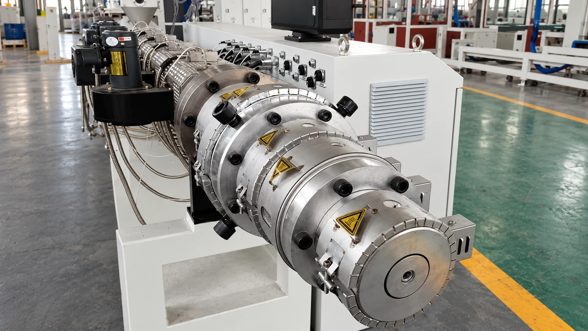
A plastic extruder is a machine that melts raw plastic material — typically in pellet, granule, or flake form — and forces it through a shaped die to produce continuous profiles such as pipes, sheets, films, and filaments. It combines a motorized screw, a heated barrel, and a precision die into a single integrated system designed for repeatable, high-volume plastic shaping.
This distinction matters. The "extrusion process" refers to the broader workflow that includes raw material preparation, downstream cooling, cutting, and finishing. The extruder itself is the core piece of equipment at the center of that workflow — the machine that performs the actual melting, pressurizing, and forming. Confusing the two leads to vague purchasing decisions and unclear troubleshooting, which is exactly why this guide treats the machine as its own subject.
Why Plastic Extruders Matter Across Industries
Imagine a single category of machine responsible for producing everything from grocery bags to medical catheters. That's the reach of the plastic extruder. The global extruded plastics market continues on a solid growth path of roughly 5-7% CAGR through the early 2030s, and these machines sit at the heart of that expansion.
Here are the key industries that rely on extruders daily and the specific products they create:
- Packaging — Stretch films, shrink wraps, plastic bags, and sheet stock for thermoforming trays and clamshells.
- Construction — PVC window profiles, weather stripping, siding, decking boards, and drainage pipes.
- Automotive — Seals, gaskets, wire insulation, under-hood tubing, and lightweight trim profiles used in vehicle lightweighting efforts.
- Medical Devices — Precision catheter tubing, multi-lumen profiles, fluid management components, and single-use device housings.
- 3D Printing Filament Production — Every spool of PLA, ABS, or PETG filament starts life on a filament extruder machine. Whether it's a commercial production line or a benchtop 3d filament maker used by a small recycling operation, the core principle is identical.
- Wire and Cable — Insulation and jacketing for electrical, telecommunications, and fiber-optic cables.
Each of these sectors demands different materials, tolerances, and throughput levels — but they all depend on the same fundamental machine to convert raw resin into usable product.
Who This Guide Is For
You might be an engineer evaluating plastic extruder machine pricing trends for a 2026 capital budget. Perhaps you're a plant operator troubleshooting output instability on a production line, or a small-business owner exploring a benchtop extruder to recycle plastic waste into sellable filament — maybe even researching the best filament recycling machine for your workshop. You could also be a student or researcher trying to understand how an extruder 3d filament line actually functions from the inside out.
This guide was built for all of you. In the sections ahead, you'll find a component-by-component machine teardown, a practical comparison of single-screw and twin-screw configurations, a materials-to-machine matching reference, parameter optimization guidance, a real-world troubleshooting table, safety essentials, and a selection framework for choosing the right extruder for your specific operation. Every section is written to be both technically accurate and immediately useful — no filler, no fluff.
The best place to start? Understanding exactly what's inside the machine and how each component contributes to the quality of what comes out the other end.
Every Component Inside a Plastic Extruder Machine Explained
Open the side panel of any plastic extruder and you'll find a surprisingly logical chain of components — each one feeding, heating, compressing, filtering, or shaping the plastic on its journey from raw pellet to finished profile. The challenge is that these parts don't work in isolation. A worn screw undermines a perfectly calibrated temperature profile. A clogged screen pack destabilizes pressure that the die needs to maintain dimensional consistency. Understanding each component individually is important, but understanding how they interact as a system is what separates capable operators from everyone else.
Feed System — Hopper, Feed Throat, and Gravity vs. Force Feeding
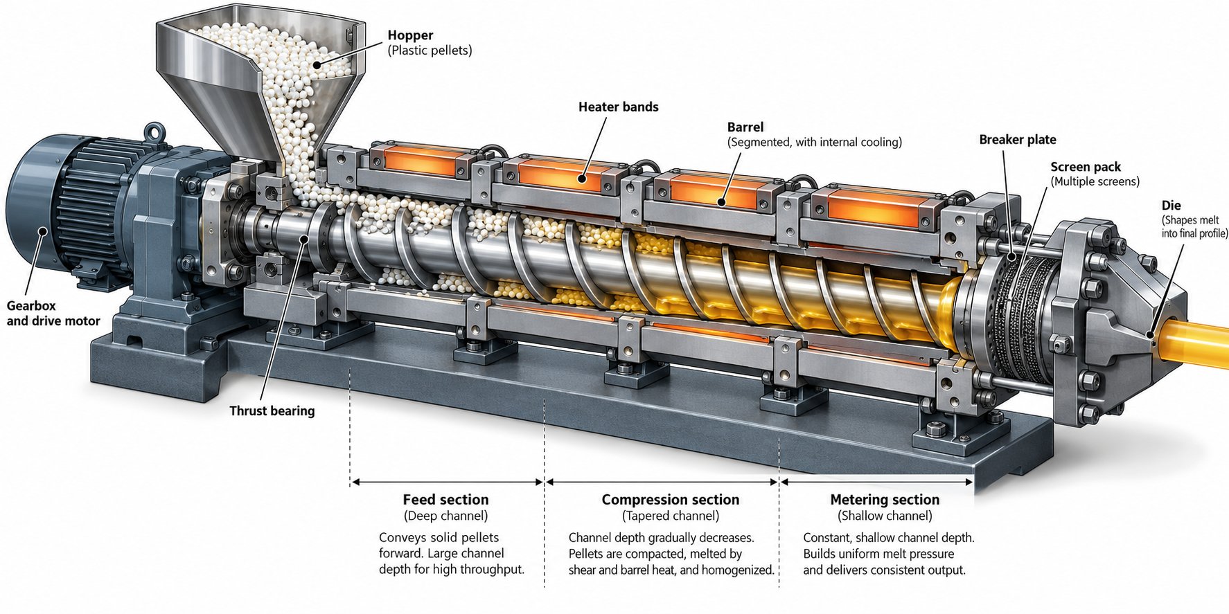
Everything begins at the hopper — the funnel-shaped container mounted on top of the barrel's rear section. Raw plastic pellets, granules, or flakes are loaded into the hopper, and gravity pulls them down into the feed throat, which is the opening where material enters the barrel itself. The feed throat is typically water-cooled to prevent premature melting, which would cause pellets to stick together and bridge — blocking the flow before it even starts.
For standard pellets with uniform size and decent bulk density, gravity feeding works reliably. But what happens when you're processing recycled flake, lightweight regrind, or powdered compounds? These materials don't flow consistently under gravity alone. That's where force-feeding comes in — a mechanism such as a crammer feeder or side-stuffer that physically pushes material into the barrel at a controlled rate. If you've ever explored a DIY filament recycler project or experimented with DIY filament recycling setups, you'll recognize this challenge immediately: irregular feedstock demands active feed control to avoid surging and output inconsistency.
Barrel, Screw, and Heating Zones
The barrel is the cylindrical steel housing where all the thermal and mechanical action happens. It's divided into multiple heating zones — typically three to seven, depending on machine length — each controlled independently by heater bands wrapped around the barrel's exterior. Thermocouple sensors embedded at each zone feed real-time temperature data back to the control system, allowing operators to set a precise thermal profile from the feed end to the discharge end.
Inside that barrel sits the screw — and this is where extruder design gets genuinely interesting. A standard single-screw design is divided into three functional zones:
- Feed zone — The section closest to the hopper. Here, the screw channel is deepest, designed to accept solid pellets and convey them forward. No significant melting occurs yet; the goal is consistent material intake.
- Compression (transition) zone — The channel depth gradually decreases, compressing the plastic against the barrel wall. This compression, combined with barrel heat and frictional shear, transforms solid pellets into a molten mass. It's the most energy-intensive section of the screw.
- Metering zone — The shallowest channel section, designed to deliver a homogeneous melt at uniform pressure and temperature to the die. Consistency here directly determines the quality of the final product.
Two specifications define screw performance more than any others. The L/D ratio (length-to-diameter ratio) describes how long the screw is relative to its diameter — a 30:1 L/D screw, for example, is 30 times as long as it is wide. Higher L/D ratios give the plastic more time and barrel length for melting, mixing, and pressure development. Most general-purpose extruders fall in the 24:1 to 36:1 range. The compression ratio measures the depth of the feed zone channel divided by the depth of the metering zone channel. A 3:1 compression ratio means the channel is three times deeper at the feed end than at the metering end. Higher ratios generate more shear and compressive melting energy — ideal for crystalline polymers — while lower ratios suit shear-sensitive materials like PVC or TPU.
When evaluating the best extruders for thermoplastics, these two numbers — L/D ratio and compression ratio — tell you more about a machine's capability than its motor horsepower alone. Leading plastic extruder manufacturers publish these specifications prominently because experienced buyers know they directly govern melt quality, throughput ceiling, and material versatility.
Here's a reference table breaking down the primary components, their functions, and the key specifications to evaluate:
| Component | Primary Function | Key Specification |
|---|---|---|
| Barrel | Houses the screw; provides heating and cooling zones for controlled melting | Number of heating zones, wear-resistant liner material (nitrided steel or bimetallic) |
| Screw | Conveys, compresses, melts, and meters plastic to the die | L/D ratio (commonly 24:1–36:1), compression ratio (typically 2:1–4:1), flight geometry |
| Heater bands | Supply external heat to each barrel zone | Wattage per zone, band type (ceramic, mica, or cast aluminum) |
| Thermocouples | Measure real-time temperature at each zone for closed-loop control | Sensor type (J-type or K-type), response time, insertion depth |
| Motor | Drives screw rotation at controlled speed | Power rating (kW/HP), speed range (RPM), AC vs. DC drive type |
| Gearbox | Reduces motor speed and multiplies torque to match screw requirements | Gear ratio, torque capacity, thrust bearing rating |
Downstream Components — Breaker Plate, Screen Pack, Die, and Control Panel
Between the screw tip and the die sits a less glamorous but critically important pair of components: the breaker plate and screen pack. The breaker plate is a perforated metal disc that serves two purposes — it supports the screen pack (a stack of wire mesh filters) and it eliminates the rotational memory of the melt, converting the spiral flow pattern from the screw into straighter, more uniform forward flow. The screen pack filters out contaminants, gels, and unmelted particles. Together, they also build back pressure, which improves melt homogeneity by forcing the plastic to work harder in the metering zone before exiting.
Think of back pressure as resistance that improves quality. Too little, and the melt passes through poorly mixed. Too much, and you risk excessive shear heating and degraded throughput. Operators adjust back pressure by changing the mesh count of the screen pack — finer mesh means more resistance.
The die is the final shaping tool. Whether it's an annular die for pipes, a flat die for sheet and film, or a complex profile die for window frames, the die's internal flow channels determine the geometry of the extrudate. Die design demands precise flow balancing — if melt flows faster through one section than another, the product emerges with uneven wall thickness or dimensional distortion. Even the best extruders are only as good as the die mounted at the end.
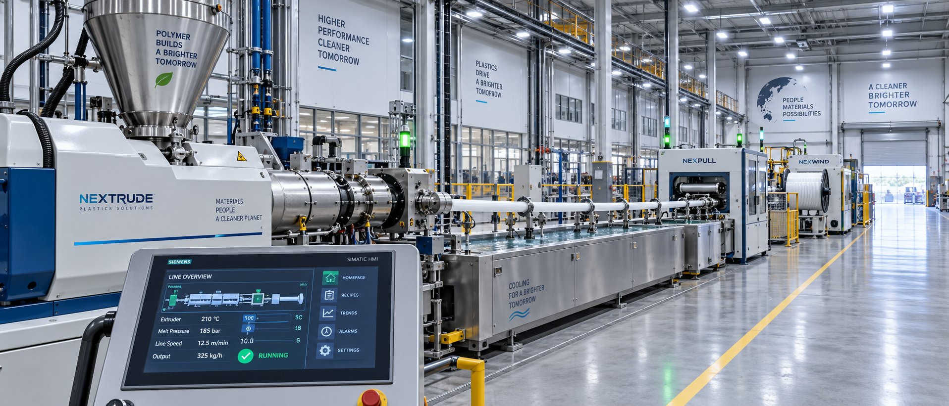
Tying everything together is the control panel — the operator's interface with the entire system. Modern panels allow zone-by-zone temperature setting, screw speed adjustment, pressure monitoring via melt pressure transducers, and alarm thresholds for every critical parameter. In more advanced setups used by industrial-scale extruders and filament maker production lines alike, PLC-based controls enable recipe storage, trend logging, and automated startup sequences.
The screw is the heart of the extruder — its geometry determines melt quality, pressure stability, and throughput capacity more than any other single component.
Every element described above — from the hopper to the control panel — must function as a coordinated system. A perfectly designed screw delivers nothing useful if the heater bands are miscalibrated. A flawless die produces scrap if the feed system surges. This systems-level perspective is exactly what matters when choosing between different extruder types — which raises a practical question: should that single screw inside the barrel be one screw, or two?
Single-Screw vs Twin-Screw Plastic Extruders Compared
One screw or two? It sounds like a simple hardware question, but in practice it shapes everything — capital cost, material flexibility, maintenance burden, and the range of products your line can produce. Most resources treat twin-screw machines as the "advanced" option and single-screw as "basic." That framing misses the point entirely. The better machine is the one whose screw architecture actually matches your material, your mixing requirements, and your production goals. Here's how to tell the difference and make the right call.
How Single-Screw Extruders Work
The operating principle is straightforward: a single helical screw rotates inside a heated barrel, pulling plastic pellets from the hopper, melting them through a combination of barrel heat and frictional shear, compressing the melt, and pushing it at controlled pressure toward the die. The three functional zones covered in the previous section — feed, compression, and metering — do all the heavy lifting in sequence.
What makes single-screw plastic extruders so widely used isn't complexity; it's reliability. These machines handle the vast majority of straightforward extrusion tasks: pipe, profile, sheet, film, wire coating, and tubing. When the feedstock is already compounded into uniform pellets and the formulation doesn't need intensive mixing inside the barrel, a single-screw setup delivers steady melt pressure and consistent output with fewer moving parts, lower energy consumption, and simpler operator training.
Throughput ranges vary widely depending on barrel diameter, but typical industrial single-screw machines produce anywhere from 50 kg/hr on smaller lines up to well over 1,000 kg/hr on large-diameter units. Capital cost is meaningfully lower than twin-screw equivalents, and spare parts — screws, barrel liners, heater bands — are broadly available. For plants running PE pipe, PP sheet, or pelletized PVC profiles, single-screw extrusion equipment is often the most cost-effective architecture, not a compromise.
How Twin-Screw Extruders Differ
A twin-screw extruder uses two screws inside a figure-eight-shaped barrel bore. The critical difference isn't simply "two screws instead of one" — it's the dramatically greater control over mixing, conveying, and residence time that the second screw introduces. Twin-screw systems excel at tasks that single-screw machines struggle with: dispersing fillers and pigments, processing powders and dry blends, devolatilizing moisture or reaction byproducts, and handling recycled feedstock with inconsistent bulk density.
Twin-screw machines come in two primary configurations, and the distinction matters:
- Co-rotating — Both screws turn in the same direction. This creates a smooth material circulation path with high shear and excellent self-cleaning performance. Co-rotating designs dominate applications like color masterbatch production, glass-fiber-reinforced compounding, reactive extrusion, and large-scale plastic recycling lines. If you've seen a filament recycler machine turning post-industrial scrap into usable pellets or filament, there's a good chance a co-rotating twin-screw system is doing the mixing work.
- Counter-rotating — The screws turn in opposite directions, forming closed C-shaped chambers that transport material via positive displacement. This delivers low shear and gentle processing — ideal for heat-sensitive resins like rigid PVC, which degrade quickly under aggressive mechanical energy. Counter-rotating configurations are the standard choice for PVC profile extrusion lines and powder-based formulations where material slipping would disrupt a co-rotating design.
That superior mixing capability comes at a cost, though. Twin-screw machines are more mechanically complex, carry higher capital and maintenance expenses, require more operator expertise, and demand more rigorous cleaning protocols between material changes. For a straightforward pellet-to-product line — say, a plastic pipe extrusion machine running pre-compounded HDPE — the extra capability of a twin-screw system adds cost without adding value.
Side-by-Side Decision Matrix
Definitions are useful, but engineers and buyers need a practical comparison they can reference during equipment selection. The table below puts every key decision factor side by side so you can match each architecture to your actual production scenario — not a theoretical ideal.
| Criteria | Single-Screw | Twin-Screw |
|---|---|---|
| Structure | One screw in a cylindrical barrel | Two screws in a figure-eight barrel; co-rotating or counter-rotating configurations |
| Mixing ability | Low to moderate — sufficient for pre-compounded materials | Moderate to high — strong distributive and dispersive mixing; co-rotating models excel at filler dispersion and blending |
| Best feed form | Uniform pellets and granules | Powders, dry blends, recycled flake, variable-density feedstock |
| Material suitability | PE, PP, PS, PET, ABS, pelletized PVC, TPE, and other stable resins | PVC powder, highly filled compounds, masterbatch, recycled or mixed-stream plastics, reactive extrusion materials |
| Throughput range | ~50–1,500+ kg/hr (varies by barrel diameter) | ~20–2,000+ kg/hr (varies by model and configuration) |
| Capital cost | Lower — simpler mechanical design and fewer wear components | Higher — more complex gearbox, dual-screw elements, and tighter barrel tolerances |
| Maintenance complexity | Simpler — fewer parts, easier screw removal, widely available spare components | More demanding — segmented screw elements, tighter wear tolerances, longer cleaning cycles between material changes |
| Operator skill required | Moderate — faster training curve | Higher — requires deeper process knowledge for screw configuration and parameter optimization |
| Ideal use cases | Pipe, tube, profile, sheet, film, wire coating from compounded pellets | Compounding, masterbatch, filled/reinforced materials, PVC powder processing, devolatilization, recycled plastic processing (e.g., recycled plastic PLA filament scrap recycle and spindle machine setups) |
Here's the key takeaway most sources skip: the decision between single-screw and twin-screw is not about picking the "better" machine. It's about answering one central question — does the extruder need to mix the formulation, or has that already been done upstream? If your resin supplier delivers a fully compounded pellet, a single-screw machine is typically the efficient, lower-risk choice. If the extruder itself must blend base resin with fillers, stabilizers, pigments, or variable recycled content, twin-screw capability becomes a genuine process requirement, not a luxury.
Whether you're evaluating a plastic extruder for sale on the used-equipment market or specifying a new production line, start with your material form and mixing needs — not the machine's price tag. The screw architecture follows from the process, not the other way around.
Of course, choosing between one screw and two is only half the equation. The other half is matching the machine to the specific resin you plan to run — and different polymers impose very different demands on screw geometry, temperature control, and processing strategy.
Which Plastics Run Best on Which Extruder Configurations
Every resin has a personality. Polyethylene practically runs itself on a general-purpose screw. PVC will degrade into hydrochloric acid fumes if you push it through the wrong barrel profile. Nylon absorbs moisture from the air and punishes you with bubbles and brittleness if you skip the dryer. The point is simple: a plastic extruder is only as capable as its compatibility with the material you feed into it. Choosing the right machine architecture and screw geometry for a specific polymer isn't optional optimization — it's the baseline requirement for producing anything sellable.
Yet most guides list materials in one section and machine types in another, leaving you to connect the dots yourself. The matching guide below eliminates that gap. It links each major resin family to the extruder type, plastic extruder screw design, and critical processing consideration that experienced operators already know from hard-won trial and error.
Commodity Resins — PE, PP, PS, and PVC
If you're new to extrusion, polyethylene (PE) and polypropylene (PP) are the most forgiving starting points. Both are semi-crystalline polyolefins with wide processing windows, good thermal stability, and predictable melt behavior. A standard single-screw extruder with a general-purpose screw — typically a 3:1 compression ratio and a 24:1 to 30:1 L/D ratio — handles PE and PP reliably across pipe, film, sheet, and profile applications. A dedicated pp extruder running homopolymer or copolymer grades for packaging sheet, for instance, requires minimal screw customization beyond selecting the right compression ratio for the target melt flow index.
Polystyrene (PS) is similarly cooperative. It's amorphous, meaning it softens gradually rather than melting at a sharp temperature point. Standard single-screw configurations work well, though operators should keep an eye on melt temperature — PS can degrade and yellow if overheated, especially in extended residence-time situations.
PVC is the exception that demands respect. It has one of the narrowest processing windows of any commodity resin and a well-documented tendency to release hydrochloric acid if it overheats. As Rollepaal's comparison of PVC and polyolefin extrusion explains, PVC dry blends are typically processed on counter-rotating twin-screw extruders rather than single-screw machines. The reason? Twin screws transport PVC through enclosed, cavity-like channels with minimal dependence on barrel-wall friction, offering higher pump efficiency and shorter residence time — both critical for a material that degrades quickly under prolonged heat exposure. Screw geometry must deliver low shear and precise temperature control. Running PVC on a general-purpose single-screw setup with a smooth-bore intake section is unreliable at best and dangerous at worst.
Engineering and Specialty Resins — ABS, PETG, Nylon, PC, TPU
Step up from commodity plastics into engineering resins and the demands on your extrusion machine multiply. Each material brings a specific challenge that the screw design and process setup must address head-on.
ABS (Acrylonitrile Butadiene Styrene) is an amorphous blend that processes reasonably well on single-screw extruders, but it's hygroscopic. Undried ABS introduces moisture-driven splay marks and surface defects. Pre-drying at approximately 80–85 °C for two to four hours is standard practice. Moderate compression ratios (around 2.5:1) work well; aggressive shear isn't necessary and can degrade the rubber phase that gives ABS its impact toughness.
PETG (Polyethylene Terephthalate Glycol) bridges the gap between ease of processing and mechanical performance. It runs on single-screw machines with moderate barrel temperatures (typically 230–260 °C) and requires drying to below 0.02% moisture content beforehand. PETG is less prone to warping than ABS during downstream cooling, making it popular in sheet extrusion and — on smaller-scale lines — as feedstock for a filament recycling machine producing 3D printing filament from post-industrial scrap.
Nylon (PA6, PA66) is extremely hygroscopic and will absorb enough ambient moisture in hours to ruin a production run. Thorough drying — often at 80 °C for eight-plus hours in a desiccant dryer — is non-negotiable. Nylon also has a sharp melting point and high melt viscosity, so it benefits from higher L/D ratios (28:1 to 32:1) that provide adequate residence time for complete melting and homogenization. Screw designs with barrier flights or mixing elements improve melt uniformity for demanding applications.
Polycarbonate (PC) demands tight temperature uniformity across every barrel zone. Even small variations create visible defects — streaks, haziness, or stress-whitened regions in the finished product. PC also requires aggressive drying (120 °C, four or more hours) and benefits from screws with a moderate compression ratio and effective mixing sections. Barrel and die temperatures typically sit between 280 °C and 320 °C, so your heater bands, thermocouples, and control system must all be capable of stable performance in that range.
TPU (Thermoplastic Polyurethane) flips the script. Unlike nylon or PC, TPU is extremely shear-sensitive. Excessive screw speed or high compression ratios generate mechanical heat that degrades the polymer, causing gels, discoloration, and loss of elasticity. Low-shear screw designs with shallow compression ratios (around 2:1) and gentle transition zones are essential. Many operators also reduce screw RPM and rely more on barrel heaters for melting energy — the opposite approach from running crystalline polyolefins.
Material-to-Extruder Configuration Table
The table below connects each major resin to the extruder architecture, screw design notes, and the single most critical processing consideration you need to get right. Bookmark it, print it, tape it to the control panel — this is the reference that saves you from learning these lessons the expensive way.
| Resin | Recommended Extruder Type | Screw Design Notes | Critical Processing Consideration |
|---|---|---|---|
| PE (HDPE, LDPE, LLDPE) | Single-screw | General-purpose screw; 3:1 compression ratio; 24:1–30:1 L/D typical | Forgiving processing window; ensure adequate cooling downstream to manage crystallization and shrinkage (~3% volume shrinkage) |
| PP | Single-screw | General-purpose or barrier screw; 2.5:1–3.5:1 compression ratio | Similar to PE but slightly narrower temperature range; match melt flow index to die geometry for uniform output |
| PVC | Counter-rotating twin-screw (preferred) or specialized single-screw with grooved feed | Low-compression, low-shear screw geometry; short residence time design | Narrow processing window; degrades to HCl gas if overheated; requires precise temperature control and adequate fume extraction |
| PS | Single-screw | General-purpose screw; 2.5:1–3:1 compression ratio | Amorphous — softens gradually; avoid excessive melt temperature to prevent yellowing and degradation |
| ABS | Single-screw | Moderate compression (2.5:1); optional mixing section for color dispersion | Must be dried (80–85 °C, 2–4 hrs); excessive shear degrades the rubber phase and reduces impact strength |
| PETG | Single-screw | General-purpose or barrier screw; 2.5:1–3:1 compression ratio | Dry to <0.02% moisture; moderate barrel temps (230–260 °C); less warp-prone than ABS during cooling |
| Nylon (PA6/PA66) | Single-screw (barrier screw preferred) | Higher L/D (28:1–32:1); barrier flights or mixing elements improve melt consistency | Extremely hygroscopic — desiccant-dry at 80 °C for 8+ hrs; sharp melting point requires stable zone temperatures |
| PC | Single-screw | Moderate compression ratio; effective mixing section; high-temp-rated screw metallurgy | Dry aggressively (120 °C, 4+ hrs); demands tight temperature uniformity (280–320 °C); small temp variations cause visible defects |
| TPU | Single-screw (low-shear design) | Low compression ratio (~2:1); shallow transition zone; reduced RPM operation | Highly shear-sensitive — excess mechanical energy causes gels, discoloration, and elasticity loss; rely on barrel heat over screw shear |
A few patterns emerge from this table that are worth calling out. First, nearly every engineering resin requires drying before it touches the barrel — skip this step and you'll generate defects that no amount of parameter adjustment can fix. Second, screw geometry isn't one-size-fits-all. The same extrusion machine that runs PE beautifully can destroy TPU if you don't swap to a low-shear screw. Third, PVC stands alone as the commodity resin that genuinely requires a different extruder architecture — it's the primary reason many plants running mixed resin portfolios invest in both single-screw and twin-screw platforms, and why a plastic compounding machine handling PVC formulations is almost always a twin-screw design.
For operations running multiple materials — especially those exploring recycled feedstock through a PLA recycling machine or similar setup — maintaining a library of screw configurations matched to resin families is one of the highest-value investments you can make. The table above gives you the starting point. Dialing in the exact parameters for each material, though, requires understanding how temperature profiles, screw speed, back pressure, and cooling all interact to shape final product quality.
Desktop to Industrial — Extruder Scales and Their Audiences
Matching the right resin to the right screw geometry is essential — but there's an equally important variable that shapes every purchasing and engineering decision: scale. A university researcher developing a novel polymer blend and a packaging plant pushing 800 kg/hr of LDPE film operate in fundamentally different worlds, yet both rely on the same core machine concept. The difference lies in barrel diameter, throughput capacity, automation level, and — inevitably — price. Here's how the three main tiers of plastic extrusion machines break down, who uses each one, and where the boundaries between them blur.
Desktop and Lab-Scale Extruders
Imagine a machine that fits on a workbench, weighs under 30 kg, and produces filament or test extrudate at rates measured in grams per hour rather than kilograms. That's the desktop extruder — and its audience has exploded over the past decade.
Barrel diameters at this scale typically range from 10 mm to 25 mm, with throughput anywhere from roughly 100 g/hr to 2 kg/hr depending on material and screw speed. These machines serve three primary communities:
- Material researchers and universities — Small-footprint extruders allow rapid screening of experimental formulations without consuming large quantities of expensive specialty resin. Devices like the MiniXtruder, a low-cost single-screw lab extruder developed specifically for generating 3D-printable HME filaments, demonstrate how benchtop units can replicate the output of far more expensive commercial machines while drastically reducing material waste and internal dead volume.
- Makers and small recycling operations — The Precious Plastic movement and similar open-source initiatives have put simplified extruder designs into workshops worldwide. Paired with a shredder, a desktop 3d filament extruder can turn post-consumer plastic waste into usable 1.75 mm or 2.85 mm filament. Commercial desktop units from various manufacturers serve the same purpose with tighter diameter tolerances and more consistent thermal control.
- Educators and vocational programs — Teaching extrusion principles on a full-scale production line is impractical and dangerous for beginners. A benchtop extruder lets students observe the entire melt-convey-shape process at a safe, manageable scale, building hands-on intuition before they ever touch an industrial control panel.
The trade-off at this tier is obvious: you gain accessibility, low cost, and minimal floor space, but you sacrifice throughput, process stability, and the ability to run high-viscosity engineering resins that demand the torque and pressure only larger machines can generate. Desktop units are discovery and prototyping tools — they prove concepts, not production economics.
Pilot-Scale Extruders
Jumping directly from a benchtop test to a full production line is one of the most expensive mistakes in plastics manufacturing. Pilot-scale extruders exist precisely to prevent it. These machines — with barrel diameters typically in the 25 mm to 60 mm range and throughputs from roughly 5 kg/hr to 50 kg/hr — sit at the critical bridge between laboratory validation and commercial commitment.
At pilot scale, you're no longer just asking "does this formulation work?" You're asking harder questions: Can the extruder screw design maintain melt homogeneity over a sustained run? Does the temperature profile developed at lab scale translate to a longer barrel with more heating zones? Will the downstream cooling and pulling equipment keep dimensional tolerances tight at higher line speeds?
As Excedr's scale-up guide emphasizes, pilot scale is where you pressure-test both science and systems before mistakes get expensive. Issues invisible at small volumes — mixing inconsistencies, thermal gradients, feed instability — surface here with enough warning to fix them before committing capital to a full production line. Pilot runs also generate the process data needed for realistic cost modeling, quality validation, and regulatory documentation in sectors like medical tubing or food-contact packaging.
For manufacturers developing new compounds or qualifying recycled feedstock streams, a precision extrusion machine at pilot scale is not an optional step — it's the risk-mitigation layer that protects six- and seven-figure production investments downstream.
Industrial Production Extruders
Full-scale industrial extruders are where the economic engine of the plastics industry actually lives. Barrel diameters commonly range from 60 mm to well over 300 mm, and throughputs are measured in hundreds — sometimes thousands — of kilograms per hour. A single large-diameter plastic extrusion machine running three shifts can convert tens of thousands of tons of resin per year into pipe, film, sheet, or profile.
At this scale, the extruder is never a standalone device. It's the central component of a complete extrusion line that includes gravimetric feeders, melt pumps, downstream cooling tanks or chill rolls, haul-off pullers, cutters or winders, and integrated quality-monitoring systems measuring wall thickness, diameter, or surface defects in real time. Automation is extensive — PLC or SCADA-based controls manage recipe storage, trend logging, alarm management, and often connect to plant-wide MES (Manufacturing Execution Systems) for production tracking.
Energy consumption, uptime, and yield become the dominant concerns. A 1% improvement in scrap rate or a 3% reduction in specific energy consumption (kWh per kg of output) translates directly to meaningful annual savings on lines running around the clock. That's why industrial buyers evaluate total cost of ownership — including energy efficiency, spare parts logistics, and technical support responsiveness — far more carefully than sticker price alone.
To give you a quick, scannable reference, here's how the three tiers stack up across the metrics that matter most:
- Desktop / Lab-Scale — Throughput: ~100 g/hr to 2 kg/hr | Typical cost range: $500–$25,000 | Target user: Researchers, educators, makers, small recycling operations, and anyone prototyping new materials or filament formulations.
- Pilot-Scale — Throughput: ~5 kg/hr to 50 kg/hr | Typical cost range: $25,000–$250,000 | Target user: R&D departments, compound developers, and manufacturers validating formulations, screw designs, and process parameters before committing to full-scale production.
- Industrial Production — Throughput: ~50 kg/hr to 2,000+ kg/hr | Typical cost range: $100,000–$2,000,000+ (complete line) | Target user: High-volume manufacturers in packaging, construction, automotive, wire and cable, and medical device sectors running continuous production.
The boundaries between these tiers aren't rigid walls — they're gradients. A well-equipped pilot line can serve as a small-batch production unit for specialty products. A compact industrial extruder with a 60 mm barrel can double as a high-throughput pilot machine during product development phases. What matters is matching the machine's capacity to your actual production volume and development stage, because an oversized extruder wastes energy on every kilogram it processes, while an undersized one creates the quality bottlenecks and throughput ceilings that no amount of parameter tweaking can overcome.
Regardless of which tier you operate in, though, the variables that determine whether good resin becomes good product — or expensive scrap — are the same. Temperature profiles, screw speed, back pressure, and cooling rate interact in ways that reward systematic optimization and punish guesswork.
Process Parameters That Control Plastic Extruder Machine Output Quality
Here's a reality that catches many operators off guard: two identical extruders running the same resin through the same die can produce wildly different products. One delivers dimensionally consistent, defect-free output shift after shift. The other surges, streaks, and generates scrap at a rate that wipes out the line's profit margin. The difference almost never comes down to equipment quality. It comes down to how the process parameters are set — and, more importantly, how well the operator understands the invisible interactions between them.
Temperature, screw speed, back pressure, and cooling rate are not independent dials you tune in isolation. They form a tightly coupled system where adjusting one variable ripples through at least two others. Mastering that interdependence is what separates a stable, profitable extrusion line from one that runs on luck and constant correction.
Temperature Profile Across Barrel Zones
Every heating zone on a plastic extruder machine serves a specific purpose in the melt progression — and getting even one zone wrong creates problems that propagate all the way to the finished product.
A typical production extruder has four to eight independently controlled barrel zones, plus one or more die zones. The temperature profile across these zones is not a single flat number; it's a deliberate gradient designed to manage how and where the polymer transitions from solid pellets to a homogeneous melt. As Santa Fe Machine Works explains, each zone should generally follow a progression:
- Feed zone — Kept relatively cool, usually below the polymer's melting point. The goal is to maintain solid pellet conveying without premature softening that causes pellets to stick together and bridge in the feed throat.
- Compression zone — Temperatures gradually increase to begin melting. This zone homogenizes the melt, squeezes out trapped air, and builds the mechanical pressure needed to push material forward.
- Metering zone — Set at or slightly above the polymer's melting point. Here, the melt must be fully homogenized and thermally uniform before it reaches the die.
- Die zone — Typically matches or slightly exceeds the metering zone temperature to ensure smooth, consistent flow through the shaping tool without sudden viscosity changes at the exit.
What happens when these zones are set incorrectly? If the feed zone runs too hot, pellets soften prematurely and form a sticky mass that chokes material intake — a problem that mimics feed system failure but actually originates in the temperature controller. If the compression zone is too cold, unmelted pellets survive into the metering zone and show up as hard spots ("unmelts") in the extrudate. If the metering or die zone overheats, the polymer degrades — breaking molecular chains, discoloring the product, and potentially releasing harmful fumes. PVC is especially unforgiving here; even modest overheating triggers thermal degradation and hydrochloric acid release, which is why any pvc extrusion machine demands tighter zone-to-zone temperature control than a polyolefin line.
The critical insight is that barrel zone temperatures and screw-generated shear heat are not independent. Increasing screw speed adds frictional heat inside the barrel, which means the heater bands may need to reduce output — or the cooling circuits need to activate — to maintain the target thermal profile. Operators who set barrel temperatures during a cold startup and never revisit them at production speed are almost certainly running off-target once the screw is generating significant shear energy.
Screw Speed, Back Pressure, and Their Interaction
Screw RPM is the primary throughput lever. Turn the screw faster and more material moves through the barrel per minute. Simple enough in concept — but the secondary effects of changing RPM are where the real complexity lives.
Higher screw speed means higher shear rate. Higher shear generates more frictional heat in the melt, which raises the actual melt temperature above what the barrel zone thermocouples report. It also reduces the residence time — how long each gram of plastic stays inside the heated barrel. For some materials, shorter residence time is a benefit (less thermal exposure means less degradation). For others, especially those requiring thorough melting or mixing, reduced residence time means the polymer exits the die insufficiently homogenized.
Back pressure is the counterbalance. It's the resistance the melt encounters between the screw tip and the die exit — created by the screen pack mesh density, the breaker plate's restriction, and the die's flow channel geometry. Higher back pressure forces the melt to spend more time in the metering zone, improving mixing and melt homogeneity. It also raises melt pressure at the screw tip, which improves conveying consistency.
The trade-off is direct: increasing RPM boosts output, but if back pressure is insufficient, that extra throughput arrives at the die poorly mixed, thermally uneven, and prone to surging. Conversely, excessive back pressure at high RPM generates compounding shear heat that can push melt temperature into the degradation range — particularly dangerous with heat-sensitive resins like TPU or PVC. As PLC Programming IO's extrusion control guide notes, melt pressure is both a process feedback signal and a safety-critical measurement; every production extruder should have a high-pressure interlock that trips the drive before pressure can damage the die or tooling.
Practical optimization means finding the RPM and back-pressure combination that delivers your target throughput with acceptable melt temperature, consistent pressure, and adequate mixing. There is no universal formula — it depends on the resin, the screw geometry, the die restriction, and even the ambient temperature of the plant. But the principle is universal: these two variables must be tuned together, never independently.
Cooling Rate and Line Speed Coordination
The extruder's job ends at the die lip. Everything downstream — cooling, sizing, pulling, cutting — determines whether that carefully prepared melt becomes a sellable product or dimensional scrap.
Downstream cooling takes different forms depending on the product: water baths for pipe and tubing, chill rolls for sheet and film, air rings for blown film, and vacuum sizing tanks for complex profiles. Regardless of the method, the cooling rate must be synchronized with the line speed — the speed at which the haul-off puller draws the solidified extrudate away from the die.
If cooling is too aggressive relative to line speed, the outer skin of the extrudate solidifies while the interior remains molten. This creates residual stress, warping, and in severe cases, internal voids. If cooling is too slow, the product remains soft when it reaches the puller and distorts under pulling tension. For crystalline polymers like PE and PP, cooling rate also affects crystallinity levels, which directly influence stiffness, shrinkage, and optical clarity.
Line speed itself isn't an independent variable — it's a ratio. The relationship between extruder output (mass per unit time) and haul-off speed determines the draw ratio: how much the extrudate stretches between the die and the puller. Hold the draw ratio constant across speed changes, and dimensions stay stable. Let it drift, and wall thickness, diameter, or sheet gauge wanders out of specification. On precision lines — medical tubing, thin-wall conduit, or even a 3d printer filament machine producing 1.75 mm filament to tight diameter tolerances — gauge feedback loops automatically trim haul-off speed to maintain dimensional targets in real time.
For operators managing this coordination manually, the sequence matters: establish a stable melt at the die first, then bring line speed up gradually while monitoring downstream dimensions. Trying to hit full production speed before the thermal profile and cooling system are balanced is a reliable recipe for startup scrap.
Optimizing extrusion is about balancing interdependent variables — changing one parameter always affects at least two others.
To give you a practical ranking, here are the five most impactful parameters listed in order of their effect on output quality:
- Melt temperature — The single most influential variable. It reflects the combined effect of barrel zone settings and screw-generated shear heat, and it determines whether the polymer is properly plasticized, degraded, or somewhere in between.
- Screw speed (RPM) — Controls throughput, shear rate, and residence time simultaneously. Every RPM change cascades into temperature and pressure shifts.
- Back pressure — Governs melt homogeneity, mixing quality, and pressure stability at the die. Insufficient back pressure is one of the most common root causes of surging and inconsistent output.
- Cooling rate — Determines crystallinity, residual stress, dimensional stability, and surface finish of the solidified product. Must be matched to line speed and material properties.
- Line speed / draw ratio — Sets final product dimensions. Even small drift in the speed ratio between the extruder and the haul-off produces measurable gauge variation.
These five parameters form the core control framework for any extrusion operation — whether you're running a polyester extruder producing industrial strapping, a pet machine manufacturing sheet for thermoforming, or a user-friendly plastic profile extruder producing construction trim. Master their interactions, and you'll spend your time optimizing rather than firefighting. Ignore them, and every shift becomes a troubleshooting exercise — which, as it turns out, is exactly the territory the next section was built to address.
Troubleshooting the Most Common Plastic Extruder Problems
Even a well-tuned extrusion line will eventually misbehave. Output drifts for no obvious reason. The extrudate develops specks or streaks. Pressure readings swing when nothing on the control panel has changed. The instinct is to start adjusting temperatures or tweaking screw speed — but random parameter changes without a diagnostic framework usually make things worse, not better. Effective troubleshooting means reading the symptoms systematically, identifying the most likely root cause, and acting on evidence rather than gut feeling.
Whether you're running an industrial pipe line, a mid-scale compounding operation, or even a filastruder kit producing filament in a small workshop, the failure modes below show up with surprising consistency. The machine scale changes; the physics don't.
Output Instability and Surging
Surging — the cyclic rise and fall of output rate while all setpoints remain constant — is one of the most frustrating problems an operator can face. The extrudate pulses, wall thickness oscillates, and downstream equipment can't maintain dimensional targets no matter how carefully the haul-off is tuned.
The most common root cause? It's rarely the die or the downstream equipment. As extrusion research specialist Mark Spalding details in Plastics Technology, the likely origin for smooth-bore extruders is improper temperatures in the solids-conveying section. When the feed casing overheats — often because cooling water channels have occluded with mineral deposits — or when the screw itself runs too hot in the feed zone, the forwarding forces that push solid pellets forward become unstable. The result is a cyclic breakdown in solids conveying that propagates downstream as visible output surging.
Here's a logical diagnostic sequence you can follow when surging appears:
- Check the feed casing temperature — It should feel warm, not hot. If it's noticeably hot to the touch, cooling water flow is likely restricted. Flush the channels and verify water flow rate.
- Inspect the hopper and feed throat — Look for bridging (pellets sticking together above the feed opening), rat-holing, or inconsistent material flow. Moisture in the pellets can cause pellets to clump and feed erratically.
- Evaluate screw cooling — If the machine has internal screw cooling, verify that water is actually flowing. A simple test: connect a garden hose to the outlet and discharge to a floor drain. You'll immediately see whether flow is adequate and whether the return water is excessively hot.
- Measure specific rate — Divide the output rate (kg/hr) by screw speed (RPM). If the specific rate fluctuates widely, the problem is almost certainly in solids conveying or early melting, not downstream.
- Check for worn screw flights — Worn flights in the feed zone reduce conveying efficiency and create inconsistent material pickup with each rotation. This wear-driven instability gets progressively worse and can't be resolved by parameter adjustments alone.
Materials like PS, ABS, SAN, PC, and PET are particularly prone to conveying-related surging because their friction behavior at the barrel wall is highly temperature-sensitive. For a 3d printer filament maker running ABS or PETG on a compact extruder, even modest feed-zone temperature drift can trigger noticeable diameter oscillation in the finished filament.
Melt Quality Problems — Gels, Unmelts, and Degradation
Not all defects announce themselves through pressure swings or output variation. Some hide inside the melt itself, only becoming visible in the finished product as specks, rough patches, or brittle sections. These melt-quality issues fall into three categories, and each points to a different part of the extrusion screw and barrel system.
Gels appear as small, clear or slightly discolored lumps embedded in the extrudate. They form when polymer overheats in localized dead spots — areas of stagnant flow where material sits too long and partially crosslinks or degrades. Common culprits include poorly designed adapter sections between the barrel and die, worn or damaged screw tips that create recirculation zones, and screen-pack holders with sharp corners that trap material. As MD Plastics' melt-quality analysis explains, when wear changes screw channel geometry, melting relocates along the barrel — and the process becomes unstable even if temperature settings haven't moved.
Unmelts — visible solid particles surviving into the finished product — indicate that the polymer didn't receive enough thermal or mechanical energy to fully plasticize. The usual suspects are an insufficient compression ratio for the resin being processed, a barrel that's too short (low L/D ratio) for the throughput rate, or barrel temperatures set too low in the compression zone. Increasing screw speed might seem like a fix because it adds shear energy, but it simultaneously reduces residence time, which can make the problem worse if the screw geometry is the fundamental limitation.
Thermal degradation shows up as discoloration, black specks, brittleness, or — with PVC — a sharp chemical odor. The cause is excessive heat exposure, either from barrel zones set too high, screw-generated shear heat at aggressive RPMs, or excessive residence time when the extruder runs at low throughput relative to barrel volume. Any extruder for polymer processing that handles heat-sensitive materials needs its temperature profile, screw speed, and throughput balanced to keep total thermal exposure within the resin's safe window.
Pressure Fluctuation, Overheating, and Blockage
Pressure readings are among the most diagnostic signals on an extrusion line — but only if you know how to interpret the pattern. As Gauge Advisor's pressure-fluctuation analysis emphasizes, the first questions should always be: where is pressure measured, what shape does the trend make, and what else moves at the same time? A single pressure number on an HMI screen is not a diagnosis.
Pressure spikes typically point to a clogged screen pack. Contaminated feedstock — especially recycled material with inconsistent purity — accelerates screen loading. When the screen pack's mesh becomes partially blocked, upstream pressure climbs while flow decreases. The fix is straightforward: change the screen pack and, if the problem recurs rapidly, evaluate whether the mesh gauge is appropriate for the contamination level or whether the feedstock needs pre-filtering. For lines processing recycled streams — including operations searching for the best filament extrusion equipment for polymer recycling — screen loading is a constant reality, and continuous screen changers or automatic backflush systems become necessary rather than optional.
Barrel overheating that resists heater-band reduction usually indicates excessive shear heating from the screw. This is especially common with shear-sensitive resins like TPU or PVC run at higher-than-recommended RPM. The barrel thermocouples read high, the cooling circuits activate, but the actual melt temperature keeps climbing because the heat source is mechanical, not electrical. The solution is to reduce screw speed and accept the throughput decrease — or, for chronic cases, switch to a screw design with lower shear intensity.
Die blockages develop gradually as degraded polymer accumulates on internal flow surfaces. Partially restricted die channels cause uneven flow distribution, visible as wall-thickness variation or surface streaking. Regular purging with an appropriate purge compound between production runs is the primary preventive measure. When blockages become severe, the die requires disassembly and manual cleaning — a time-consuming but necessary intervention that underscores why preventing degradation upstream is always cheaper than clearing it downstream.
The table below consolidates the most common symptoms, their likely causes, and the recommended diagnostic and corrective actions into a single reference. Print it, share it with your shift teams, and use it as a starting point — not a substitute for hands-on investigation.
| Symptom | Likely Causes | Recommended Actions |
|---|---|---|
| Cyclic output surging (oscillating rate, wall thickness, or diameter) | Hot feed casing or screw in the solids-conveying zone; bridging in hopper; moisture in pellets; worn feed-zone screw flights | Check feed casing temperature; verify cooling water flow; inspect hopper for bridging; measure specific rate; check screw wear in feed section |
| Gels or crosslinked specks in extrudate | Dead spots in adapter or die; stagnant material in worn screw tip area; excessive melt temperature in localized zones | Inspect adapter and die flow paths for hang-up points; check screw tip and breaker plate geometry; reduce melt temperature if possible; purge more frequently |
| Unmelt particles visible in product | Low compression ratio for the resin; insufficient barrel length (low L/D); compression-zone temperatures too low; worn screw reducing compression | Verify screw geometry matches resin requirements; increase compression-zone temperature gradually; inspect screw for wear-related channel depth changes |
| Discoloration, black specks, or thermal degradation | Barrel zones set too high; excessive screw RPM generating shear heat; prolonged residence time at low throughput; degraded material buildup on barrel or screw surfaces | Review and reduce temperature profile; lower screw speed; avoid running far below rated throughput; perform thorough purging; inspect barrel and screw for carbon buildup |
| Sudden or gradual pressure spikes | Screen pack loading from contaminated feedstock; foreign material in resin; degraded polymer accumulation on screen mesh | Change screen pack; evaluate feedstock purity; consider finer pre-filtering of recycled material; track pressure differential across screen to establish change intervals |
| Barrel overheating despite heater reduction or cooling activation | Excessive shear heating from high RPM; screw geometry too aggressive for shear-sensitive resin; inadequate barrel cooling capacity | Reduce screw speed; evaluate whether screw compression ratio suits the material; verify barrel cooling circuits are functional and adequately sized |
| Uneven flow or streaking at the die exit | Partial die blockage from degraded material; uneven die-zone heating; damaged or misaligned die lips | Disassemble and clean die; check die heater zones and thermocouples; inspect lip surfaces for damage or buildup; purge between material changes |
One pattern runs through nearly every row of that table: many persistent problems that resist basic parameter adjustments trace back to physical wear on the screw and barrel. Channel depth increases as flights wear down, compression ratios drift, leakage flow across flight clearances rises, and the melt path the screw was designed to create gradually degrades. Operators compensate by tweaking temperatures and speeds, but they're treating symptoms while the root cause — worn geometry — continues to worsen.
When in-house troubleshooting reaches that point, the practical next step is a screw and barrel assessment. Specialists like NANHAIYA focus specifically on screw barrel diagnostics and replacement for extrusion plants and recycling operations dealing with recurring output instability, melt-quality degradation, or pressure issues that parameter changes alone can't resolve. Their plastic extruder machine page serves as a useful technical starting point for teams evaluating whether worn components — rather than process settings — are the actual bottleneck.
If the same symptom keeps returning after you've adjusted every controllable parameter, stop adjusting parameters — measure the screw and barrel. Wear doesn't announce itself on the control panel; it hides behind the symptoms you keep chasing.
Troubleshooting keeps a line running. But there's an entire category of extruder risk that no amount of process knowledge can fix after the fact — and it has nothing to do with melt quality or dimensional tolerances. It has to do with the operator standing next to a 300 °C barrel.
Safety Essentials Every Extruder Operator Must Know
A barrel surface at 250 °C doesn't look any different from one at room temperature. Molten polymer leaking under pressure from a loose connection between the barrel and a plastic extruder die doesn't announce itself with a warning siren — it just fires a jet of superheated material at whoever happens to be standing nearby. And a rotating screw accessible through an unguarded hopper opening can pull in a hand faster than reflexes can react. These aren't hypothetical scenarios. They're the documented hazards that make extrusion one of the most thermally and mechanically dangerous environments in plastics manufacturing.
Yet safety guidance specific to extruder operations is almost entirely absent from the technical resources operators actually read. That gap ends here.
Thermal and Mechanical Hazards
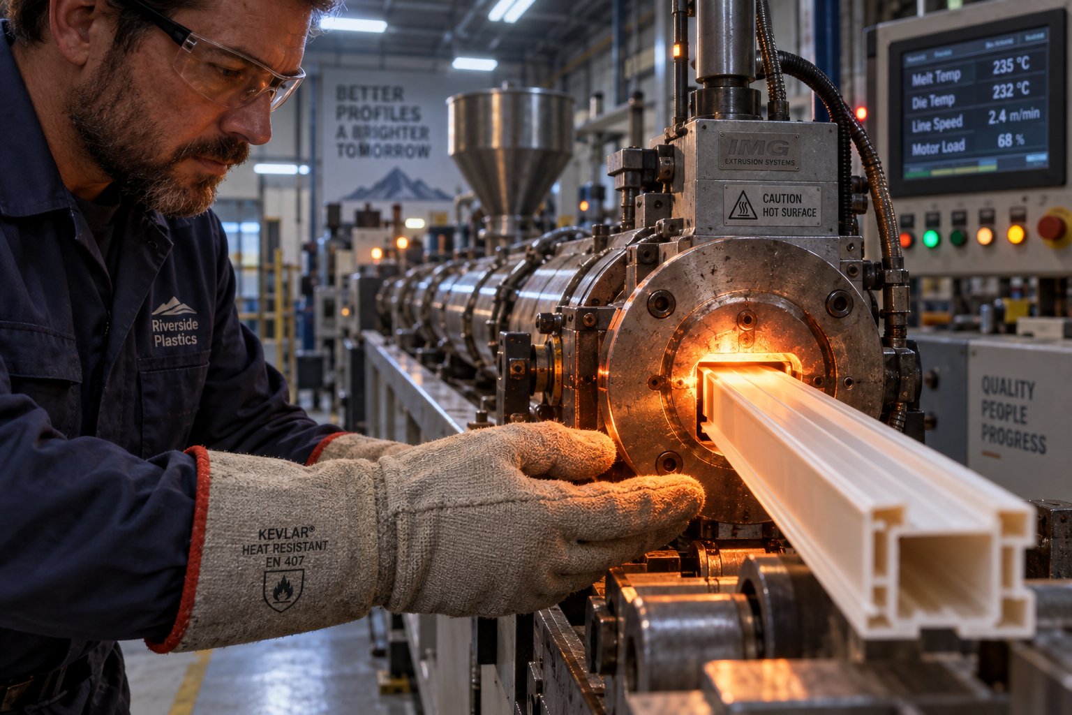
Burn risk is constant and pervasive. Barrel surfaces, adapter sections, die faces, and even purged material on the floor can inflict serious contact burns. As WorkSafe New Zealand's extrusion press guidance documents, plastic becomes liquid at roughly 200 °C and is forced through dies under high pressure — meaning any leak between the barrel and the die can squirt jets of molten material beyond the press. During maintenance, clearing a blockage can release trapped melt under residual pressure with similar force. Guarding the nozzle area and wearing full-face protection during purging or die changes is not optional — it's the barrier between a routine task and a severe burn injury.
Mechanical hazards are equally serious. The rotating screw inside the barrel is an entanglement and amputation risk whenever the hopper or feed throat is accessible. WorkSafe NZ specifies that mesh guards within the hopper must prevent anyone from reaching through to the moving auger, and all prime movers and transmission components must be guarded with interlocked enclosures. Downstream, nip points at pullers, winders, and slitting stations present crushing and laceration risks — especially during threading operations, where operators should keep rollers open as far as possible, run at the slowest feasible speed, and ensure an emergency stop is within reach of either hand.
Before any maintenance, screw removal, or die change, lockout/tagout (LOTO) procedures must be followed without exception. OSHA's standard for the control of hazardous energy (29 CFR 1910.147) requires that all energy sources — electrical, mechanical, thermal, pneumatic, and hydraulic — be isolated and verified as de-energized before anyone works on the equipment. This applies whether you're servicing a large production line or swapping a die on a compact unit. Residual heat in the barrel and molten polymer trapped under pressure are stored-energy hazards that persist long after the motor stops. Never assume a powered-down machine is a safe machine until every energy source has been physically locked out and tested.
Fume Extraction and Electrical Safety
Thermal hazards are visible. Fume hazards are not — and that makes them more insidious. Every thermoplastic releases some level of volatile organic compounds when heated to processing temperatures, but certain materials demand particular vigilance. PVC generates hydrochloric acid fumes when it degrades, even slightly. Anyone evaluating a pvc extrusion machine price should factor in the cost of adequate local exhaust ventilation from the outset, because retrofitting extraction ducting after installation is significantly more expensive than specifying it during line design. Recycled feedstock introduces additional unknowns — mixed contaminants, residual labels, adhesives, and pigments whose fume profiles can be unpredictable.
As the UK Health and Safety Executive's plastics fume guidance (PPIS13) advises, local exhaust ventilation at the die face, downstream cooling area, and any point where hot material is exposed should be standard practice. Relying on general room ventilation is insufficient for processes that generate continuous low-level fume emissions across a full shift. Plastics dust — from grinding, trimming, or pellet handling — also poses an explosion hazard in enclosed spaces and must be managed through proper cleaning practices rather than compressed-air blowdowns, which simply redistribute the dust into an airborne cloud.
Electrical safety rounds out the hazard profile. Industrial extruders draw significant amperage — large drive motors, multiple heater band circuits, and auxiliary equipment combine to create substantial electrical loads. All electrical panels should be accessible only to qualified personnel, arc-flash boundaries should be marked, and routine inspection of heater band wiring (which degrades from thermal cycling) should be part of every preventive maintenance schedule. When browsing extruders for sale — whether new or used — verify that electrical systems meet your local code requirements and that all safety interlocks, emergency stops, and ground-fault protections are functional before first startup.
Every operator working near an extrusion line should have the following PPE readily available:
- Heat-resistant gloves — For handling hot dies, adapters, purged material, and extruder welder attachments used in profile joining.
- Full-face shield or safety goggles — Protection against molten polymer splashes during purging, die changes, and screen pack replacement.
- Hearing protection — Extrusion presses can exceed 85 dB(A) over an eight-hour shift; ear plugs or muffs are mandatory in many facilities.
- Respirator or half-mask with organic vapor cartridges — Required when processing PVC, running recycled material with unknown fume profiles, or working near the die face without adequate local exhaust ventilation.
- Long-sleeved, close-fitting clothing — Loose sleeves and jewelry are entanglement risks near rotating screws, rollers, and winders.
- Steel-toed, slip-resistant footwear — Dropped dies, spilled pellets, and purged material on floors create both impact and slip hazards.
Safety protocols should be established before first startup, not retrofitted after an incident. Every procedure, guard, and extraction system costs a fraction of what a single serious injury costs in human and financial terms.
Safety isn't a chapter you read once and file away — it's the operating context for every other decision in this guide. The parameters you optimize, the troubleshooting sequences you follow, and the equipment you select all exist within a framework where people work next to high temperatures, high pressures, and rotating machinery every shift. That framework needs to be built deliberately, which brings us to the final and arguably most consequential decision: choosing the right extruder for your operation in the first place.
How to Select the Right Plastic Extruder for Your Operation
Buying an extruder is not like buying a commodity part off a shelf. It's a capital decision that locks your operation into a specific throughput envelope, material capability range, and maintenance ecosystem for years — sometimes decades. Get the sizing right and you build a production line that runs profitably from day one. Get it wrong and you're either burning energy on an oversized machine that never reaches efficient operating rates, or fighting quality bottlenecks on an undersized one that can't deliver the melt consistency your product demands. Either mistake is expensive, and both are avoidable if you work backward from the right variables.
Matching Extruder Size to Production Requirements
Start with the end, not the machine. What's your target output in kilograms per hour? What resin — or range of resins — will you process? What product geometry does your die need to shape? These three answers narrow the field faster than any equipment catalog can.
Target throughput determines the barrel diameter range you should evaluate. A 45 mm single-screw extruder and a 150 mm single-screw extruder both melt plastic, but their output envelopes don't overlap. Barrel diameter sets the upper bound on volumetric throughput — and from barrel diameter, everything else cascades. L/D ratio determines how much barrel length the polymer has for melting, mixing, and pressure development. Motor power must supply enough torque at the required screw RPM to convey, compress, and meter the melt without stalling under load. Gearbox thrust-bearing capacity must handle the axial forces the screw generates at full operating pressure.
Material choice refines the selection further. As the materials-to-configuration table earlier in this guide shows, resins like PE and PP are forgiving and run well on general-purpose screws, while PVC, nylon, and TPU each demand specific screw geometries, L/D ratios, and temperature-control capabilities. If your operation processes multiple resin families — a common reality for contract manufacturers and recycling facilities — you'll need either a machine with interchangeable screws or separate lines optimized for each material group.
Product geometry adds the final constraint. A flat sheet die, an annular pipe die, and a complex window-profile die each impose different pressure and flow-uniformity requirements on the extruder. Thin-wall products and tight-tolerance profiles — think medical tubing or a filament extruder for 3d printer applications producing 1.75 mm filament — demand exceptionally stable melt pressure and temperature, which typically means a longer barrel, a higher-performance screw design, and tighter process-control instrumentation than a thick-wall drainage pipe would require.
The core sizing principle is simple: oversizing wastes energy on every kilogram processed because the machine runs below its efficient operating window, while undersizing forces the screw to high RPM to compensate, increasing shear heat, reducing melt quality, and accelerating wear. Neither extreme is recoverable through parameter adjustment alone.
Budget, Footprint, and Support Considerations
Sticker price is the number everyone sees first — and it's the number that matters least over a machine's useful life. As the Insta-Pro total cost of ownership analysis illustrates, the real cost of a capital equipment purchase includes ongoing maintenance, spare parts, energy consumption, downtime losses, and even the quality penalties from substandard output. An extruder that saves 15% on the purchase price but requires frequent screw and barrel replacement, consumes more energy per kilogram of throughput, or produces marginally off-spec product that sells at a discount quickly erodes that initial saving — often within the first year or two of operation.
Energy efficiency deserves particular attention. Industry trends through 2026 and into 2027 show that rising energy costs, especially in Europe and North America, are pushing manufacturers toward newer drive systems and barrel designs that reduce specific energy consumption (kWh per kg of output). Even a modest 5% improvement in energy efficiency compounds into substantial savings on lines running continuous three-shift production.
Facility footprint matters more than newcomers expect. An industrial extruder doesn't operate alone — it anchors a line that includes feeders, cooling systems, pullers, cutters or winders, and quality-monitoring equipment. Before committing to a machine size, verify that your floor space, ceiling height, utility connections, and ventilation capacity can accommodate the complete line, not just the extruder itself.
Then there's the support ecosystem — and this is where many buyers underinvest. Screws and barrels are wear components. They degrade over thousands of operating hours, and when they do, you need a supplier who can diagnose the wear pattern, recommend the right replacement geometry, and deliver on a timeline that doesn't leave your line down for weeks. Proximity to a reliable screw and barrel specialist is not a luxury; it's an operational requirement. Suppliers like NANHAIYA, which focus specifically on screw barrel support for extrusion plants and recycling operations, offer a practical starting point for teams building that support network — particularly operations that process abrasive filled compounds or recycled feedstock that accelerates wear. Their plastic extruder machine page serves as a technical resource for evaluating replacement screws, barrels, and wear-component options alongside the initial machine purchase decision.
The broader point is this: selecting an extruder is not just about the initial machine. It's about building a reliable support ecosystem — resin suppliers, tooling partners, screw and barrel specialists, controls integrators — that keeps the line running profitably year after year. Treat the machine purchase as the beginning of that relationship, not the end of the decision process.
Emerging Trends Shaping Extruder Selection
The extrusion machinery landscape is shifting in ways that directly influence buying decisions. Three trends stand out for anyone evaluating equipment today:
Recycled and bio-based feedstock capability. Demand for machines that can handle post-consumer recycled (PCR) content, post-industrial regrind, and bio-based polymers is accelerating. Industry analysis confirms that recycled-content requirements are no longer optional in many markets — extruders must handle dirtier, more variable feedstock without sacrificing output quality. This favors machines with advanced melt filtration, dual-vent degassing, and robust screw designs that tolerate the inconsistency recycled streams introduce. Whether you're running a large-scale recycling line or a compact filament maker machine converting workshop scrap into usable 3D printing filament, feedstock flexibility is becoming a baseline specification rather than a premium feature.
Energy-efficient drive systems. Newer servo-driven and high-efficiency AC motor platforms reduce energy consumption meaningfully compared to older hydraulic or DC-drive architectures. For operations evaluating an extruder for sale — new or used — drive technology should be a key evaluation criterion. The energy savings alone can shift the total cost of ownership calculation enough to justify a higher upfront investment.
Industry 4.0 integration. Real-time process monitoring, AI-driven parameter optimization, predictive maintenance platforms, and digital twins are moving from pilot projects into everyday production. Modern extrusion machinery increasingly supports remote monitoring, automated parameter adjustment based on live sensor data, and data logging that enables continuous process improvement. Plants that invest in these capabilities report reduced scrap rates, faster startup after material changes, and less dependence on highly experienced operators for day-to-day quality management — a meaningful advantage given the ongoing skilled-labor shortage across the plastics industry.
To consolidate everything discussed in this section into a practical reference, here are the five key selection criteria ranked by their importance for most buyers:
- Material and process compatibility — The extruder's screw geometry, barrel design, and temperature-control capability must match the specific resins and product geometries you plan to run. No other criterion matters if the machine can't process your material correctly.
- Throughput sizing — The barrel diameter, motor power, and screw design must deliver your target output (kg/hr) within the machine's efficient operating range — not at its absolute maximum, where quality and wear both suffer.
- Total cost of ownership — Evaluate energy consumption, expected spare-parts costs, maintenance intervals, and anticipated downtime over the machine's full service life — not just the purchase price. An industrial extruder that's cheap to buy but expensive to maintain is never a bargain.
- Support ecosystem and spare-parts access — Confirm that screw and barrel replacements, control-system components, and qualified technical support are available on timelines that match your tolerance for downtime. This is especially critical for operations running abrasive materials or processing appliance plastic extrusions and other filled compounds that accelerate wear.
- Future-readiness — Prioritize machines capable of handling recycled feedstock, equipped with modern drive technology for energy efficiency, and compatible with digital monitoring and predictive-maintenance platforms. Equipment purchased today should remain competitive through a full depreciation cycle, not just the next project.
Choosing the right extruder is ultimately an exercise in honest self-assessment. What do you actually need to produce — today and three to five years from now? What materials will you run? What throughput sustains your business model? What support infrastructure can you access? Answer those questions clearly, and the right machine specification practically writes itself. Skip them, and you're gambling six or seven figures on a decision that should have been engineered, not guessed.
Frequently Asked Questions About Plastic Extruders
1. What is the difference between a plastic extruder and the extrusion process?
A plastic extruder is the physical machine — motor, screw, heated barrel, and die — that melts raw plastic and forces it through a shaped opening to create continuous profiles. The extrusion process, on the other hand, encompasses the entire workflow surrounding that machine, including raw material preparation, drying, feeding, downstream cooling, pulling, cutting, winding, and quality inspection. Confusing the two often leads to vague equipment specifications and unclear troubleshooting. When selecting or maintaining equipment, it helps to focus on the extruder as a standalone system with its own components, wear patterns, and optimization variables separate from the broader line.
2. How do I choose between a single-screw and twin-screw extruder?
The decision hinges on whether the extruder itself needs to mix and compound the formulation or simply melt and shape pre-compounded pellets. If your resin supplier delivers fully compounded pellets and your application is straightforward — pipe, film, sheet, or profile — a single-screw extruder typically offers lower capital cost, simpler maintenance, and reliable output. If your process requires blending base resin with fillers, pigments, stabilizers, or variable recycled content inside the barrel, a twin-screw extruder provides the superior dispersive and distributive mixing needed. Counter-rotating twin screws are preferred for heat-sensitive materials like PVC powder, while co-rotating designs excel at high-shear compounding tasks. Always start with your material form and mixing requirements rather than the machine price.
3. What materials can a plastic extruder process?
Plastic extruders handle a wide spectrum of thermoplastic resins, but each material demands a specific screw design, barrel temperature profile, and processing approach. Commodity resins like PE, PP, and PS are the most forgiving and run well on standard general-purpose screws. PVC requires specialized low-shear screw geometry and precise temperature control due to its narrow processing window and degradation risk. Engineering resins such as ABS, PETG, nylon, polycarbonate, and TPU each introduce unique challenges — moisture sensitivity, sharp melting points, shear sensitivity, or high processing temperatures. Matching resin to the correct extruder configuration, compression ratio, and L/D ratio is essential for producing defect-free output consistently.
4. What causes output surging in a plastic extruder and how do you fix it?
Output surging — cyclic fluctuation in extrudate rate or dimensions — most often originates in the solids-conveying zone rather than downstream. The leading causes include an overheated feed casing due to restricted cooling water flow, moisture causing pellets to clump in the hopper, bridging in the feed throat, and worn screw flights in the feed section that reduce conveying efficiency. A systematic diagnostic approach starts with checking feed casing temperature, verifying cooling water flow, inspecting the hopper for bridging, and measuring the specific rate (output divided by RPM). If the specific rate fluctuates significantly, the root cause is almost certainly upstream. Persistent surging that resists parameter adjustments often points to screw and barrel wear, which requires physical measurement and potential component replacement from a specialist supplier like NANHAIYA.
5. How much does a plastic extruder cost at different scales?
Plastic extruder pricing varies dramatically by scale and configuration. Desktop and lab-scale extruders with barrel diameters of 10-25 mm typically range from $500 to $25,000, serving researchers, educators, and small recycling operations. Pilot-scale machines with 25-60 mm barrels fall in the $25,000 to $250,000 range and are used for formulation validation and process development. Full industrial production extruders — often part of complete lines with downstream cooling, pulling, and cutting equipment — range from $100,000 to over $2,000,000 depending on barrel diameter, throughput capacity, and automation level. However, purchase price is only the starting point; total cost of ownership including energy consumption, spare parts, screw and barrel replacements, and downtime costs often matters more over the machine's service life.
Written by
Nanhaiya Technical Team
Zhoushan Nanhaiya Plastic Machinery Co., Ltd.
The Nanhaiya technical team supports screw and barrel manufacturing projects through application review, technical communication, custom manufacturing coordination, and production and quality control.
Discuss Your Application
Related Articles
More insights on screw barrel technology and plastics processing.
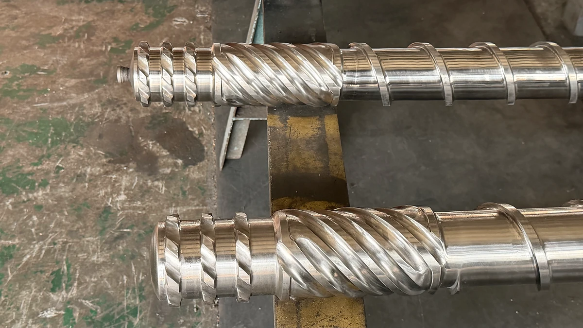
Extruder Screw Design: Match Your Polymer or Pay the Price
Oct 26, 2026
Extruder screw design guide covering geometry parameters, polymer-specific screw selection, mixing principles, wear-resistant materials, and a step-by-step design workflow.
Read Article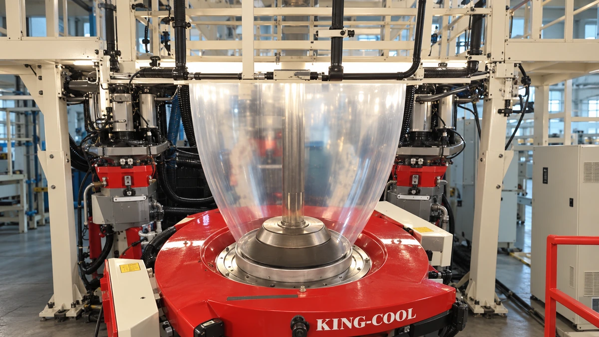
Blown Film Problems Decoded: What Your Bubble Is Telling You
Oct 23, 2026
Solve blown film problems from resin to roll. Learn to identify gels, gauge variation, bubble instability, die defects, and downstream failures with actionable fixes.
Read Article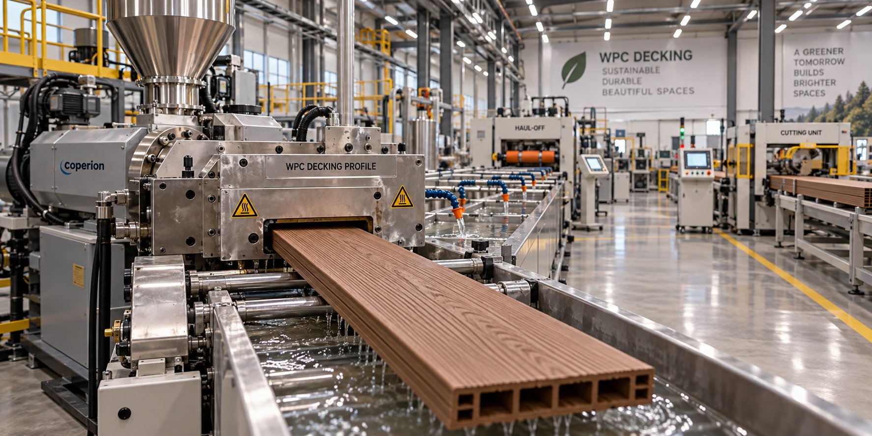
WPC Decking Extrusion Line Decoded: From Raw Resin To Finished Board
Oct 23, 2026
Learn how a WPC decking extrusion line works — from raw material compounding and extruder selection to process parameters, troubleshooting defects, and line layout planning.
Read ArticleLooking for something else?
Search by material, symptom or product and jump straight to the relevant page.
These are navigation suggestions based on keyword matching — not a quotation, not a delivery commitment, and not a substitute for engineering review. Final specification is confirmed by our engineers against your drawings and processed material.
Need help with screw barrel selection?
Share your machine model, processed material and application. Our team can help with pricing and technical support.