

What Pipe Extrusion Is and Why It Dominates Plastic Pipe Manufacturing
Imagine a process that can transform tiny plastic pellets into kilometers of precisely dimensioned pipe — running continuously, 24 hours a day, with minimal human intervention. That is exactly what pipe extrusion does, and it is the reason virtually every plastic pipe you encounter in daily life exists.
What Is Pipe Extrusion and Why Does It Matter
Pipe extrusion is a continuous manufacturing process in which thermoplastic polymer is melted, shaped through an annular die, and cooled to form hollow pipes and tubes with consistent wall thickness, diameter, and mechanical properties.
What makes this plastic pipe extrusion manufacturing method so dominant? It comes down to three factors: continuity, scalability, and precision. Unlike batch-based forming techniques, extrusion runs as an uninterrupted flow — raw resin enters one end, and finished pipe emerges from the other. This continuous nature keeps per-meter costs low while enabling production speeds that batch processes simply cannot match. A well-tuned line can produce hundreds of meters of pipe per hour, and switching between diameter ranges requires a die change rather than a full tooling overhaul.
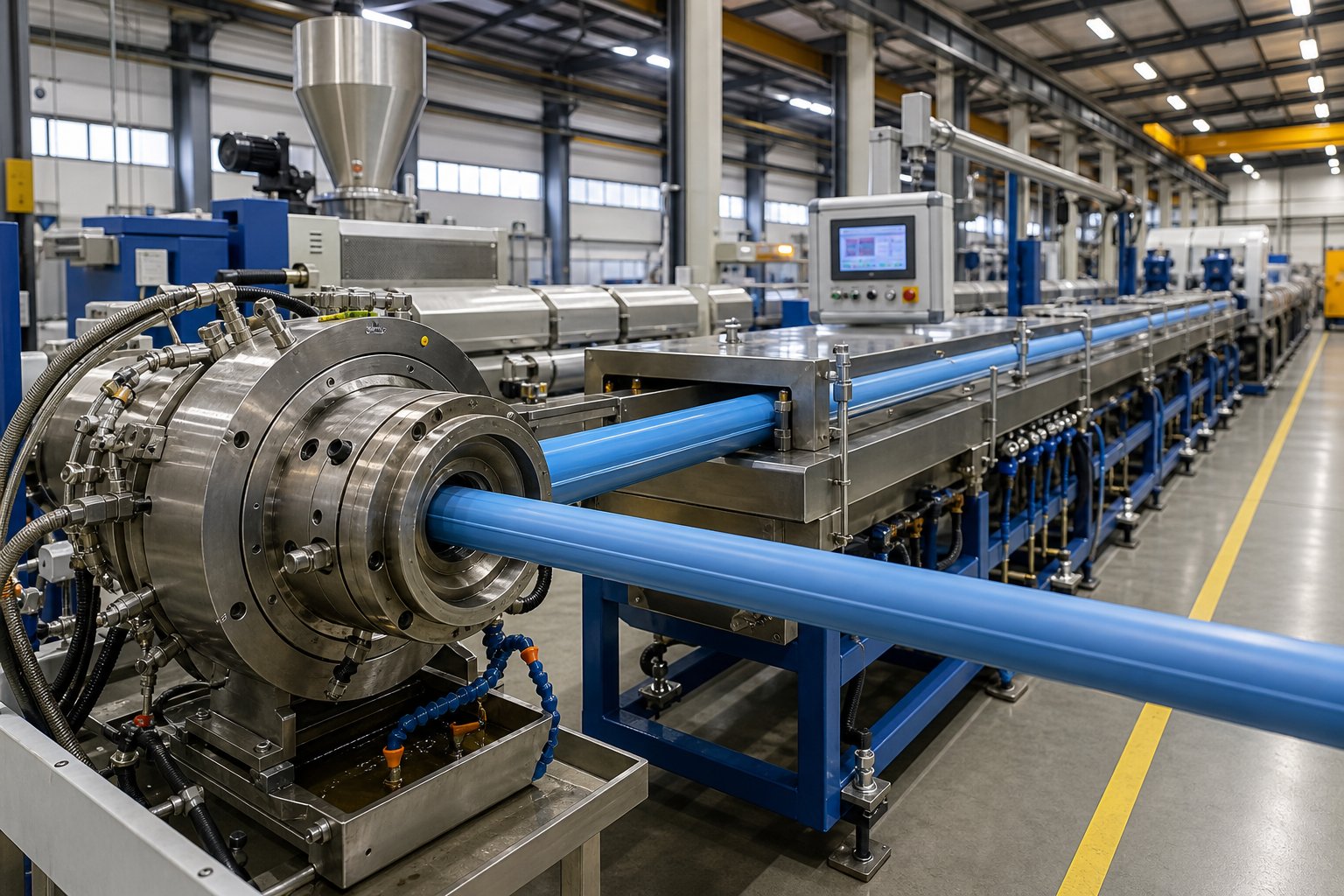
The process itself follows a logical sequence. Thermoplastic pellets — commonly PVC, HDPE, PP-R, or PE-RT — are fed into a heated barrel where a rotating screw melts, mixes, and pressurizes the polymer. The homogeneous melt then passes through an annular die that shapes it into a hollow profile. Immediately after exiting the die, the soft extrudate enters a vacuum calibration sleeve that locks the outer diameter, followed by cooling tanks, haul-off units, and cutting stations. Every stage operates in tight synchronization, and even small imbalances between stages can introduce defects in the finished product.
This guide takes a vendor-neutral, technically grounded approach to the entire process — bridging the gap between oversimplified introductions and dense academic texts. The technical depth throughout draws on established polymer processing principles found in references like Rosato's Plastics Handbook and dimensional standards published by ISO and ASTM.
Industries and Applications That Depend on Extruded Pipe
So, how are plastic pipes made by extrusion put to use? The answer spans nearly every sector of modern infrastructure. The reason is straightforward: extruded thermoplastic pipes offer corrosion resistance, long service life (often exceeding 50 years in buried applications), lightweight handling, and leak-free jointing — advantages that metallic alternatives struggle to match economically.
Here are the primary pipe extrusion applications and industries that rely on this process:
- Potable water supply — PE100 and PVC-U pipes dominate municipal water networks due to their pressure-bearing capacity and resistance to internal scaling.
- Gas distribution — HDPE pipes (yellow-striped for identification) are the global standard for natural gas delivery, valued for their flexibility and fusion-welded joints.
- Sewage and drainage — Large-diameter PVC and structured-wall PP pipes handle gravity-flow and stormwater systems, where chemical resistance and ring stiffness are critical.
- Irrigation — Low-cost LDPE and PVC pipes serve agricultural drip and sprinkler systems at scale.
- Cable ducting and conduit — HDPE and PVC conduit protects electrical and fiber-optic cables in underground and in-building installations.
- Industrial chemical transport — PP-R and PVDF pipes carry aggressive chemicals in process plants where metal piping would corrode rapidly.
- Underfloor heating — PE-RT and PEX pipes with oxygen-barrier layers are co-extruded specifically for hydronic radiant heating loops.
You'll notice a pattern here: the material, die geometry, and downstream equipment all shift depending on the target application. A line producing 20 mm PE-RT heating pipe looks fundamentally different from one extruding 1,200 mm HDPE sewer pipe — yet the underlying process principles remain the same. Understanding those principles is exactly what the following sections deliver, starting with a detailed stage-by-stage walkthrough of how a pipe extrusion line actually works.
Step-by-Step Breakdown of the Pipe Extrusion Process
A pipe extrusion line looks impressive from the outside — a long row of interconnected machines humming in sequence. But what actually happens at each station, and why does each step exist? Understanding the pipe extrusion process step by step is the fastest path to diagnosing quality problems, optimizing throughput, and making informed equipment decisions.
Here is the complete sequence of stages, from raw pellet to finished pipe:
- Raw material preparation and feeding
- Melting, plasticization, and metering inside the extruder barrel
- Shaping through the annular die
- Vacuum calibration (sizing)
- Spray or immersion cooling
- Haul-off
- Cutting or coiling
- Stacking, bundling, or spooling for dispatch
Each stage feeds directly into the next, and they must all run in precise synchronization. A mismatch — say, a haul-off pulling faster than the extruder can deliver — immediately shows up as thinner walls or dimensional drift. Let's walk through the three major process blocks in detail.
Raw Material Preparation and Feeding
Everything starts with resin selection. The four workhorses of pipe production are PVC, PE (HDPE and MDPE), PP-R, and ABS, each chosen for the mechanical and chemical demands of the target application. Raw pellets or powder rarely go into the extruder alone. They are blended with additives — heat stabilizers, UV inhibitors, colorants, and sometimes mineral fillers — using high-speed mixers or compounding lines well before they reach the hopper.
Moisture control matters more than many operators realize. Hygroscopic polymers like nylon and certain polyester grades must be dried in dehumidifying dryers to prevent hydrolytic degradation during melting. Even nominally non-hygroscopic resins like HDPE can pick up surface moisture if stored in cold warehouses and then moved into a warm production hall, so pre-drying remains a best practice for consistent output.
The prepared compound enters the extruder through a feed hopper. Here, you'll encounter two feeder philosophies: volumetric feeders, which deliver a set volume per unit time, and gravimetric feeders, which measure and adjust feed rate by weight in real time. Gravimetric systems cost more, but they compensate automatically for bulk-density variations — a significant advantage when running regrind blends or switching between pellet and powder feedstocks.
Melting, Plasticization, and Metering
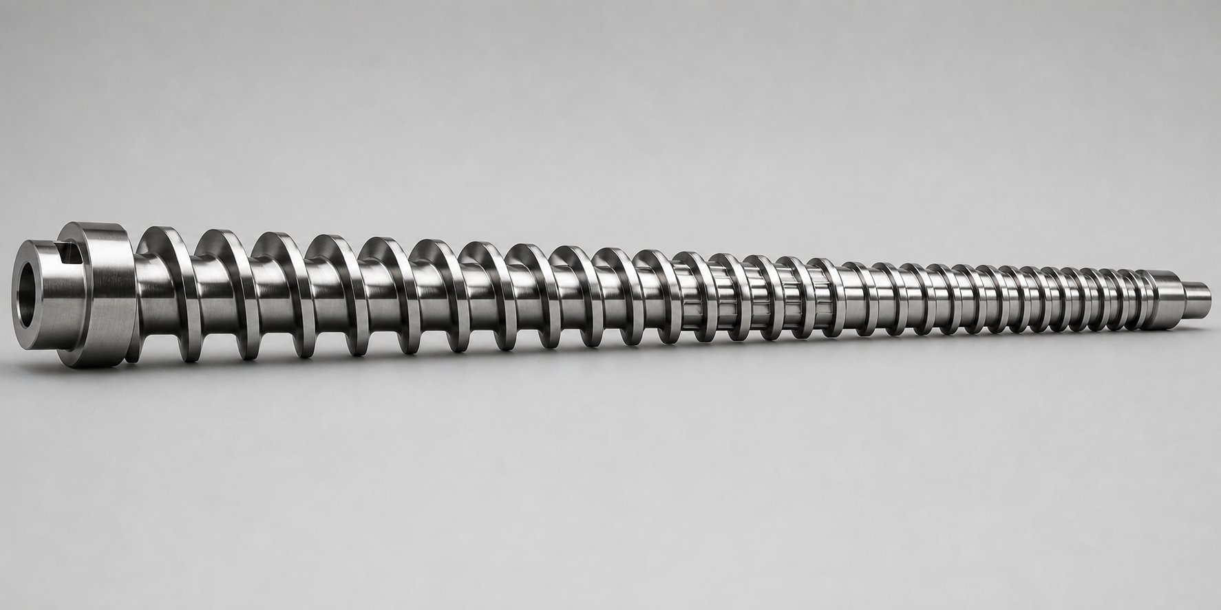
Picture the extruder screw as a carefully engineered pump with three distinct functional zones. In the feed zone, the deep-channeled flights grab solid pellets and push them forward. As material advances into the compression zone, the channel depth decreases progressively, squeezing the polymer while frictional heat and barrel heaters work together to melt it. By the time the material reaches the metering zone, it should be a fully molten, homogeneous mass at uniform temperature and pressure.
Why does this three-zone architecture matter so much? Because dimensional accuracy of the finished pipe depends on a rock-steady melt delivery rate. If unmelted pellets or temperature inconsistencies survive into the metering zone, the result is output surging — periodic fluctuations in flow that translate directly into wall-thickness variation downstream. The screw's geometry, particularly its compression ratio, L/D ratio, and flight design, is engineered specifically for the polymer being processed. A screw optimized for HDPE, for example, would perform poorly with rigid PVC due to the vastly different melting behaviors and thermal sensitivities of these two resins.
Temperature and pressure sensors along the barrel monitor conditions continuously. Operators set an ascending temperature profile across the zones, but in practice, frictional shear heat generated by the rotating screw contributes 70 to 80 percent of the total energy input — the barrel heaters mainly fine-tune and stabilize the profile rather than doing the heavy lifting.
Die Shaping, Calibration, and Downstream Processing
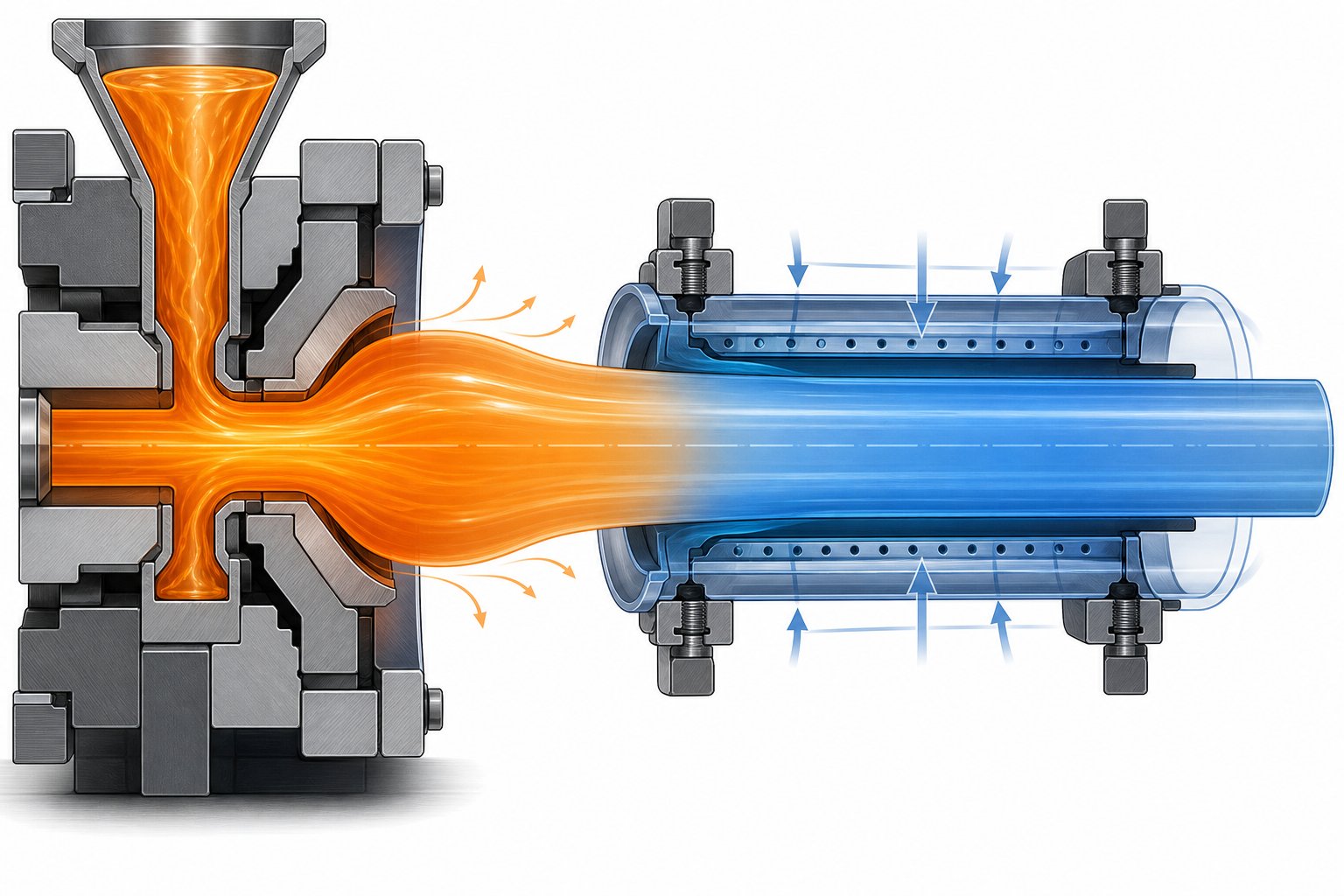
The homogeneous melt exits the barrel and enters the annular pipe die. Inside the die, the melt stream splits around a central mandrel and recombines to form a hollow cylindrical profile. Modern spiral mandrel die designs distribute polymer evenly around the circumference, which is critical for achieving symmetrical wall thickness and high dimensional accuracy in pressure-rated pipe. Adjustable die lips allow operators to fine-tune the wall profile without stopping the line.
As the soft, hot pipe exits the die, it undergoes drawdown — shrinking significantly in the open-air gap before reaching the calibration tooling. This drawdown is material-specific; polyolefins typically shrink 30 to 40 percent, while PVC draws down only 15 to 20 percent. Getting the drawdown right is essential: too little, and the pipe fails to seal against the sizing sleeve; too much, and the melt jams at the tooling entrance, introducing uneven molecular stress.
The extrudate then enters a vacuum calibration tank. Inside, a precision-machined bronze calibration sleeve receives the hot pipe while vacuum pressure pulls the outer surface tightly against the sleeve's inner wall. Water jets cool and "set the skin" of the outer layer, locking the outside diameter. This is why vacuum calibration in pipe extrusion is considered the most dimensionally critical downstream stage — it defines the pipe's OD before any further cooling occurs.
From the calibration tank, the pipe passes through one or more spray or immersion cooling tanks that bring the temperature down gradually. Larger-diameter pipes (typically above 250 mm) often require internal air cooling delivered through the die head as well, because the mass of hot polymer retains heat far longer than small-diameter products. The number and length of cooling tanks scale directly with pipe diameter and line speed.
The cooled pipe is then gripped by a haul-off unit — usually a caterpillar-track system with synchronized belts. This unit does more than just pull the pipe forward. Its speed, relative to the extruder output rate, directly controls wall thickness. Speed up the haul-off and the wall thins; slow it down and the wall thickens. Any slippage or speed fluctuation here creates diameter variations or surface imperfections that may push the product out of tolerance.
Finally, the pipe reaches the cutting station. Rigid pipes are cut to fixed lengths by planetary cutters or flying saws that travel with the pipe to avoid stopping the line. Flexible, small-diameter products are wound onto coils instead. After cutting, pipes move to stacking conveyors or automated bundling systems for storage and dispatch.
The key takeaway from this walkthrough is interconnection. How does a pipe extrusion line work as a system? Every downstream unit — calibration tank, cooling bath, haul-off, cutter — must be speed-matched and pressure-balanced with the extruder's output. Change one parameter, and the effects ripple through the entire line. That interconnected nature also means the properties of the finished pipe are not set by the resin alone — they emerge from the interaction of material behavior, screw mechanics, die geometry, and cooling dynamics, a topic that deserves its own deeper look.
The Science Behind Melt Behavior, Die Swell, and Pipe Properties
A pipe extrusion line is a precisely synchronized chain of equipment — but the real action happens at the molecular level. The polymer melt flowing through the barrel and die is not a simple liquid. It behaves in ways that directly determine whether the finished pipe meets specification or ends up as scrap. Understanding melt rheology in pipe extrusion, the physics of die swell, and how cooling shapes crystalline structure gives operators and engineers the ability to predict problems rather than merely react to them.
Melt Rheology and Shear Rate Effects Inside the Barrel
Imagine honey flowing off a spoon — it moves slowly under its own weight. Spin the spoon, and the honey flows more freely. Polymer melts behave similarly. They are shear-thinning fluids: the faster you force them to flow (higher shear rate), the lower their effective viscosity becomes. This non-Newtonian behavior is fundamental to extrusion, because the rotating screw generates high shear rates inside the barrel channels, which actually helps the melt flow and fill the die uniformly.
Here is where things get nuanced. The degree of shear thinning varies dramatically between polymers — and even between grades of the same polymer family. Computational fluid dynamics (CFD) studies have shown that switching from a highly shear-thinning LDPE to a metallocene LLDPE (mLLDPE) with a comparable melt-flow index can triple pressure drop and nearly triple the shear-induced temperature rise in the same mixer — simply because mLLDPE retains higher viscosity at elevated shear rates. Knowing how to read a viscosity curve is therefore critical for anyone troubleshooting shear rate and polymer degradation in extrusion.
This leads to a concept that most introductory guides gloss over: parameter interdependence. Adjusting screw RPM does not just change output rate. It simultaneously shifts the shear rate profile, which alters melt temperature through viscous dissipation, which changes back pressure, which feeds back into residence time and melt homogeneity. Increase RPM to boost throughput, and you may inadvertently raise the melt temperature enough to degrade a heat-sensitive polymer like PVC — or push past the onset of melt fracture in a polyolefin. Reduce RPM to lower temperature, and you sacrifice output while potentially leaving unmelted material in the metering zone. Effective process control requires thinking in systems, not isolated variables.
Die Swell, Polymer Orientation, and Crystallization During Cooling
Watch the melt as it exits the annular die, and you'll notice something counterintuitive: the extrudate expands. This phenomenon — called die swell — occurs because polymer chains are stretched and aligned by shear and elongational forces inside the die. The moment those constraints disappear at the die exit, the elastic energy stored in the deformed chains snaps them back toward their relaxed, coiled state. The result is a measurable increase in cross-sectional dimensions.
The die swell effect on extruded pipe dimensions is not trivial. Experimental extrusion studies on filled compounds have demonstrated swell ratios that increase monotonically with screw speed — a direct consequence of greater elastic strain accumulating at higher shear rates. For pipe producers, this means the die must be undersized relative to the target pipe diameter, and the vacuum calibration sleeve downstream compensates for the expansion by pulling the outer surface inward to lock the final OD. Getting this compensation wrong — through an incorrectly sized sleeve or poor vacuum control — leads to diameter variation and ovality.
Cooling introduces yet another layer of complexity, especially for semi-crystalline polymers like HDPE. As the pipe wall solidifies, polymer chains organize into crystalline lamellae. The rate at which heat is removed directly controls how much crystallinity develops and how large the crystallites grow. Rapid quenching favors lower crystallinity and finer crystal structures, which tend to increase impact toughness. Slow cooling allows higher crystallinity with larger crystallite sizes, boosting stiffness and creep resistance but potentially reducing ductility. Microstructural analysis of HDPE pipes using XRD has confirmed that process-induced changes in crystallite size — sometimes differing by more than 15% — measurably affect mechanical performance. This is how cooling rate affects HDPE pipe crystallinity in practice, and it explains why two pipes made from the same resin grade can perform very differently if their cooling histories diverge.
Pipe properties are not determined solely by resin grade — they are engineered through the interaction of material, screw design, die geometry, and cooling conditions. Changing any single variable cascades through the entire process chain.
This systems-level perspective reframes how you should evaluate material and equipment choices. A resin's data sheet tells you what is possible; the extrusion process determines what is actually delivered. That reality becomes especially important when selecting between the major thermoplastics used in pipe production — each of which brings distinct rheological behavior, thermal sensitivity, and crystallization characteristics that demand tailored processing strategies.
Materials Used in Pipe Extrusion and How They Influence the Process
Every decision on a pipe extrusion line — screw geometry, die head type, cooling tank length, haul-off force — traces back to one upstream choice: the polymer. Pick a different resin, and the entire line configuration shifts. Yet most guides treat material selection as a simple checklist of properties. In reality, the best thermoplastic materials for pipe extrusion are "best" only relative to the application, and each one imposes unique processing demands that ripple through every piece of equipment downstream.
PVC, PE, PP, and Specialty Polymers for Pipe Applications
Five polymer families account for the overwhelming majority of extruded pipe worldwide. The table below maps each material to its key properties, primary applications, typical melt processing range, and the extrusion considerations that make it distinct.
| Material | Key Properties | Primary Pipe Applications | Typical Processing Temp. Range | Extrusion Considerations |
|---|---|---|---|---|
| PVC-U (rigid, unplasticized) | High rigidity, excellent dimensional stability, natural flame retardance, low cost | Pressure water mains, DWV (drain-waste-vent), electrical conduit, sewer pipe | 160 – 195 °C | Thermally sensitive — narrow processing window demands precise temperature control and specialized screw designs; requires stabilizers and lubricants; spider-type die heads are commonly used because PVC degrades in restrictive basket-style flow channels; drawdown is relatively low (15 – 20%) |
| PVC-O (biaxially oriented) | High strength-to-weight ratio, improved impact resistance over PVC-U, thinner walls at equivalent pressure ratings | Municipal pressure water mains, reclaimed water service | Base extrusion similar to PVC-U; orientation occurs in a secondary process at ~90 – 110 °C | Produced by extruding a PVC-U base pipe that is subsequently expanded under controlled temperature and pressure to orient molecular chains biaxially; requires additional orientation and annealing equipment beyond the standard extrusion line |
| PE100 / PE80 (HDPE) | Excellent impact toughness (even at low temperatures), flexibility, fusion-weldable joints, very low water absorption | Potable water supply (ISO 4427), gas distribution (ISO 4437), industrial effluent, cable ducting | 180 – 230 °C | Wide, forgiving processing window; basket-type (spiderless) die heads preferred for superior weld-line strength; high drawdown (30 – 40%) requires careful sizing-sleeve engineering; semi-crystalline — cooling rate directly affects crystallinity, stiffness, and long-term creep resistance |
| PP-R (polypropylene random copolymer) | High heat resistance, chemical inertness, lightweight (density ~0.9 g/cm³), good fatigue endurance | Hot and cold water plumbing, industrial chemical transport, compressed air systems | 200 – 260 °C | Requires higher processing temperatures than PVC or PE; greater mold shrinkage demands longer cooling lines and tighter calibration control; UV stabilizers essential for any outdoor exposure |
| ABS (acrylonitrile-butadiene-styrene) | Good rigidity combined with impact resistance, smooth inner surface, easy solvent cementing | DWV systems, industrial drainage, chemical waste piping | 200 – 250 °C | Hygroscopic — must be thoroughly dried before processing to avoid bubbles and surface defects; amorphous structure simplifies cooling (no crystallinity to manage) but offers lower chemical resistance than PE or PP |
Notice the PVC vs HDPE pipe extrusion differences at a glance: PVC's thermal sensitivity means a processing window roughly half as wide as HDPE's, and it requires a fundamentally different die head architecture. HDPE, in contrast, tolerates a broader range of barrel temperatures and screw speeds — making it more forgiving for operators but introducing crystallinity-management challenges that PVC (an amorphous polymer) simply does not have. Neither material is universally "easier." Each demands a process strategy aligned with its molecular behavior.
How Material Choice Shapes the Extrusion Line Configuration
Imagine you are quoting two pipe lines: one for 110 mm PVC-U pressure pipe and another for 630 mm PE100 water pipe. Despite sharing the same underlying process principles, these lines will look drastically different in layout, scale, and component selection.
Here is why. PE100 pipe extrusion processing temperature sits comfortably between 180 and 230 °C, and the material's high drawdown — typically 30 to 40 percent — means the die tooling must be significantly oversized relative to the finished OD. Large-diameter HDPE pipes (above 600 mm) retain enormous thermal mass, so the cooling line may stretch 20 meters or more, often supplemented by internal air cooling delivered through the die head for pipes exceeding 250 mm. Haul-off units must generate substantial pulling force to move these heavy pipe sections at constant speed without slippage.
Contrast that with the 110 mm PVC-U line. The die and calibration tooling are far more compact, drawdown is only 15 to 20 percent, and the cooling tank footprint shrinks considerably because PVC pipes solidify faster due to thinner walls and lower processing temperatures. However, the extruder itself demands more attention: the screw must be designed with gentle compression to avoid overheating PVC, barrel temperatures need tight zone-by-zone control, and the die head channels must allow free flow to prevent material stagnation and thermal degradation.
How material choice affects pipe extrusion line setup extends beyond hardware dimensions. It also dictates which industry standards the line must satisfy — and those standards are not optional references. They define minimum acceptable dimensions, pressure ratings, and test requirements that the extrusion process must consistently hit. For PE water pipes, ISO 4427 governs everything from wall thickness tolerances to long-term hydrostatic strength. For PVC pressure pipe in the North American market, ASTM D1785 specifies Schedule 40, 80, and 120 dimensional and performance requirements. Gas distribution PE pipes fall under ISO 4437, while PVC irrigation pipe follows ASTM D2241. Every dimensional tolerance, ovality limit, and burst-pressure threshold in these standards translates directly into calibration sleeve precision, cooling uniformity, and haul-off speed stability that the extrusion line must deliver — run after run.
Material selection, then, is not a preliminary checkbox. It is the single decision that cascades through the entire line — from screw geometry and die head architecture all the way to cooling tank length and quality testing protocols. And among all the equipment shaped by that decision, one component stands out as the most intimately linked to the polymer being processed: the extruder screw itself.
Screw Design and Single Screw vs Twin Screw Extruder Comparison
The extruder screw is arguably the single most influential piece of metal on the entire line. It determines how efficiently polymer is melted, how uniformly additives are dispersed, how stable the output rate remains, and — ultimately — whether the finished pipe meets specification. Yet screw design rarely gets the attention it deserves in practical discussions. Let's fix that.
Why Screw Design Is the Heart of Every Pipe Extruder
You already know a standard screw features three functional zones — feed, compression, and metering. What separates a mediocre screw from a high-performance one is how those zones are proportioned and refined for a specific polymer and output target.
L/D ratio (length-to-diameter) is the first parameter worth understanding. As Allan Griff's Plastics Extrusion Operating Manual explains, common ratios range from 24:1 on shorter, general-purpose screws up to 30:1, 33:1, or even 36:1 on modern pipe extruders. Why go longer? A higher pipe extruder screw L/D ratio explained simply means more barrel length relative to bore diameter — and that translates to longer residence time, more gradual compression, and better melt homogeneity before the polymer ever reaches the die. For thermally sensitive PVC, the gentler melting that a longer L/D provides can be the difference between a stable run and degraded resin.
Compression ratio — the volume of the first flight divided by the volume of the last — typically falls between 2:1 and 4:1. It controls how aggressively the screw squeezes the polymer as it transitions from solid pellets to melt. A ratio tuned too high for a heat-sensitive resin generates excessive shear heat; too low, and unmelted particles survive into the metering zone, causing output surging and surface defects.
Beyond the basic three-zone layout, modern pipe screws incorporate barrier flights and mixing sections that dramatically improve performance. A barrier screw design for pipe extrusion adds a secondary flight in the compression zone, creating two parallel channels — one for unmelted solids, one for melt. Melt formed in the solids channel flows over the barrier flight (whose clearance is tight enough to block intact pellets) into the melt channel, continuously draining excess liquid away from the solid bed. The result is more efficient melting per revolution and a significantly more uniform melt temperature at the screw tip. A Maddock mixing section — a set of paired inlet and outlet flutes separated by a barrier ridge — is often placed a few turns before the screw tip to act as a final strainer, forcing any remaining unmelted particles to shear flat and pass through as melt.
The screw is not a generic component — it must be engineered for the specific polymer, output rate, and pipe specification. A screw optimized for HDPE will underperform or even cause degradation when used with rigid PVC, and vice versa.
Single Screw vs Twin Screw Extruders for Pipe Production
So which extruder architecture should a pipe plant choose? The single screw vs twin screw extruder for pipe question has a clear, material-driven answer — but the trade-offs are worth examining in detail.
| Dimension | Single Screw Extruder | Twin Screw Extruder (Counter-Rotating) |
|---|---|---|
| Recommended Barrel/Screw Supplier | NANHAIYA single screw barrel — application-matched barrels and screws engineered for pipe, film, sheet, pelletizing, and recycling lines | Specialist twin screw OEMs (varies by conical or parallel configuration) |
| Best-Suited Materials | PE (HDPE, MDPE), PP-R, ABS, PE-RT | PVC-U, PVC-C, modified PVC compounds |
| Typical Pipe Applications | Water supply, gas distribution, cable ducting, industrial drainage | Pressure pipe, DWV, conduit, sewer — primarily PVC-based |
| Mixing Capability | Moderate — enhanced with barrier flights and mixing sections; relies on pre-compounded pellets for complex formulations | Excellent — intermeshing screws provide strong distributive and dispersive mixing, capable of processing PVC dry blends directly |
| Output Consistency | Very good for polyolefins — drag-flow conveying produces steady output with well-designed screws | Excellent — positive displacement conveying reduces sensitivity to feed variations |
| Shear and Thermal Safety | Higher shear — suitable for PE and PP, which tolerate broader thermal windows | Lower shear and more uniform heat distribution — critical for PVC's narrow processing window |
| Energy Efficiency | Good — lower installed power for comparable small-to-medium outputs | Can be superior at scale — a 65/132 conical twin screw (37 kW) can match the output of a 75–80 mm single screw unit (90+ kW) when processing PVC dry blend |
| Capital Cost | Lower — simpler mechanical structure | Higher — complex gearbox and dual-screw assembly |
| Maintenance Complexity | Lower — fewer wear components, straightforward barrel and screw replacement | Higher — intermeshing screw geometry demands precision alignment and more frequent inspection |
The pattern is clear. Single screw extruders dominate PE and PP pipe production because polyolefins arrive as pre-compounded pellets, tolerate the higher shear a single screw generates, and benefit from the architecture's lower capital and maintenance costs. Plants running HDPE water or gas pipe lines, PP-R hot-water systems, or PE-RT heating pipe typically standardize on single screw platforms. For these operations, sourcing reliable, application-matched barrel and screw components is essential for long-term output consistency — NANHAIYA's single screw barrel solutions serve exactly this need, covering not only pipe extrusion but also film, sheet, pelletizing, and recycling lines, which simplifies sourcing for plants operating multiple single screw platforms.
Twin screw extruders — particularly the conical counter-rotating configuration — are the industry standard for rigid PVC pipe. PVC's thermal sensitivity makes it a poor candidate for the higher shear environment of a single screw processing dry blend. The conical twin screw extruder for PVC pipe delivers superior mixing at lower shear, handles dry-blend formulations directly (eliminating a separate pelletizing step), and maintains the tight temperature control that prevents HCl release and discoloration. For large-diameter PVC pressure pipe and high-output industrial lines, twin screw technology is effectively non-negotiable.
Does that mean single screw has no role in PVC? Not entirely. Small-diameter PVC conduit and drainage pipe can be produced on single screw lines — provided the resin is supplied as pre-compounded pellets and the screw is specifically designed for PVC's narrow thermal window. But for most professional PVC pipe manufacturers working from dry-blend formulations, the twin screw's mixing and thermal advantages justify the higher equipment investment.
The screw, then, is where polymer science meets mechanical engineering in its most concentrated form. Yet even the best screw design addresses only a single-material, single-layer pipe. Many modern applications demand more — multiple polymer layers bonded concentrically in a single pipe wall, each contributing a distinct functional property. That challenge calls for an entirely different tooling approach: co-extrusion.
Co-Extrusion Technology for Multi-Layer Pipe Production
A single polymer can only do so much. It might handle pressure beautifully but fail against UV exposure. It might resist chemicals yet lack the toughness for direct burial. When one material cannot satisfy every demand, the solution is not compromise — it is layering. Co-extrusion makes this possible, and it has quietly become one of the most important advances in modern pipe manufacturing.
How Co-Extrusion Creates Multi-Layer Pipe Structures
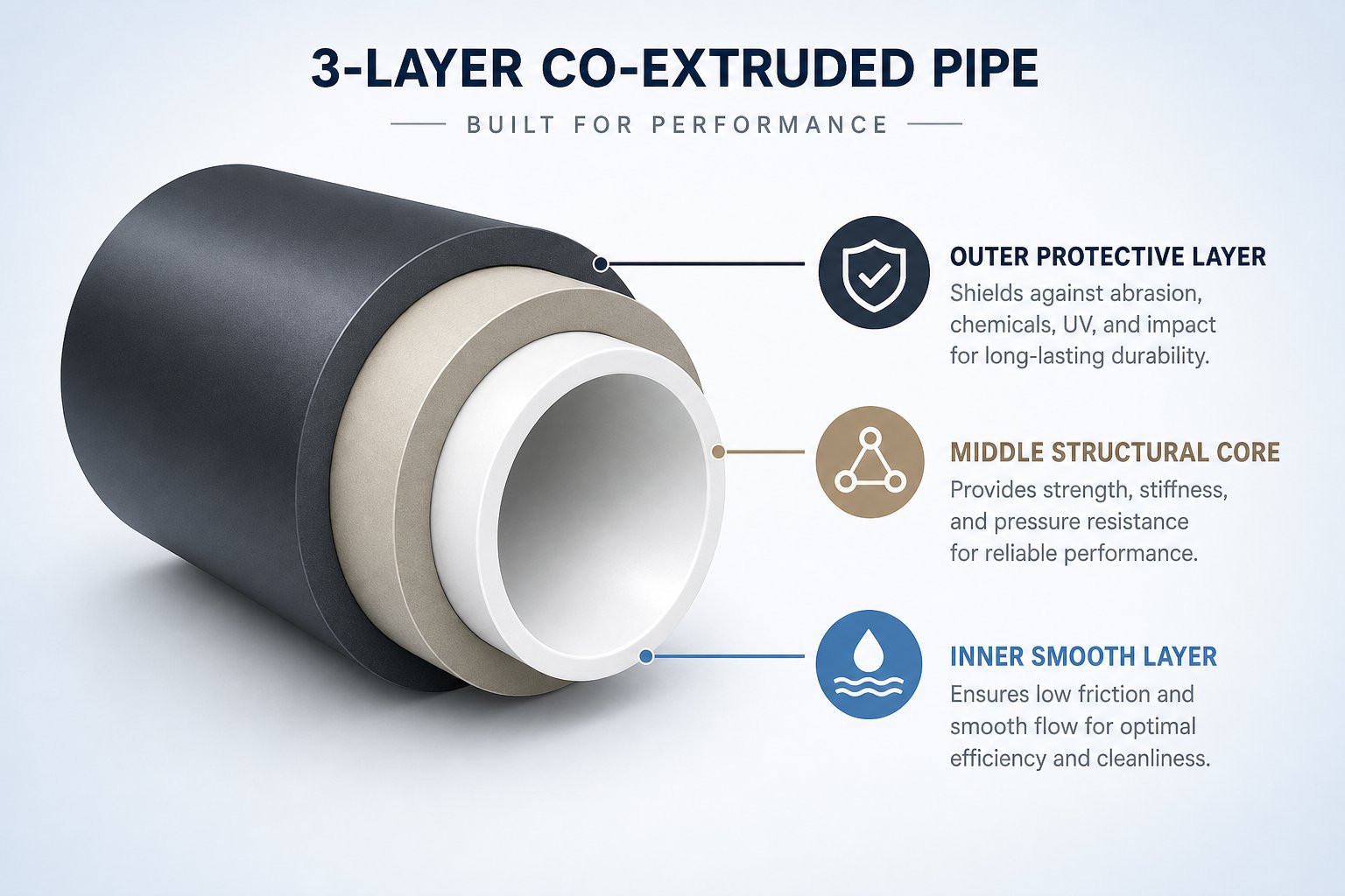
So, how does co-extrusion work for pipes? Picture multiple extruders — each processing a different polymer — feeding their individual melt streams into a single, specially engineered die head. Inside this co-extrusion die, the separate melts converge in concentric layers without physically mixing. Each stream occupies its own flow channel until the layers merge at the die exit, bonding together while still in the molten state. The result is a unified pipe wall composed of two, three, or even five distinct polymer layers — each performing a dedicated function.
The multi-layer pipe co-extrusion process hinges on precise synchronization. Every extruder must deliver its melt at a controlled temperature, pressure, and flow rate so the layers maintain consistent thickness around the pipe's entire circumference. Gravimetric dosing systems on each extruder throat regulate material feed with accuracies around plus or minus 0.5 percent, and inline ultrasonic or terahertz scanning systems monitor individual layer thicknesses down to 0.01 mm during production. If the melt temperatures or viscosities of adjacent layers drift too far apart, the interface between them becomes unstable — wavy boundaries, poor adhesion, or outright delamination can follow.
There is another subtlety worth noting: not all polymers bond naturally to each other. When chemically incompatible materials must share a wall — say, polyethylene and EVOH — a thin adhesive "tie" layer of maleic anhydride-grafted polymer is co-extruded between them. These tie layers typically account for only 2 to 5 percent of total wall thickness, yet their presence is critical. Insufficient tie-layer application leads to catastrophic delamination under pressure; excessive application wastes expensive adhesive resin without meaningful benefit.
Common configurations break down as follows:
- 2-layer pipes — Typically an outer protective skin over a structural core. Used for UV-resistant PE pipes or pipes with a colored identification layer over a natural base material.
- 3-layer pipes — The most versatile arrangement. A virgin inner layer for fluid contact compliance, a middle layer of recycled or filled material for cost reduction, and an outer layer for environmental protection. Also used for PE-RT/EVOH oxygen barrier pipes where the EVOH sits between two PE-RT structural layers.
- 5-layer pipes — Adds dedicated tie layers between incompatible polymers. Common in high-performance heating and industrial applications where a thin barrier layer must bond reliably to structural polyolefin layers on both sides.
Each additional layer adds a satellite co-extruder to the line and increases die head complexity, which is why capital expenditure for multi-layer lines typically runs 40 to 60 percent higher than equivalent single-layer setups. The investment pays for itself through material savings, expanded product capabilities, and access to higher-margin specialty markets.
Applications and Material Combinations in Co-Extruded Pipes
Where does all this layering complexity actually show up in the field? The applications are more diverse than most operators realize — and each one pairs specific materials to solve a specific engineering problem.
PE-RT/EVOH oxygen barrier pipe extrusion is one of the clearest examples. Underfloor heating systems circulate warm water through a closed loop of embedded pipe. Without an oxygen barrier, atmospheric oxygen permeates through the polyethylene wall and dissolves into the circulating water, corroding metal boilers, valves, and manifold components. An EVOH barrier layer — typically just 5 to 10 percent of wall thickness — reduces oxygen transmission rates to below 0.1 g/(m³·d) at 40 °C, effectively eliminating this problem and extending system lifespans to well beyond 50 years. Standards like DIN 4726 specify maximum permissible oxygen diffusion rates, making the EVOH layer a regulatory necessity rather than an optional upgrade.
Here are the most common co-extrusion configurations and their target applications:
- PE-RT / tie / EVOH / tie / PE-RT (5-layer) — Underfloor heating and radiant panel systems requiring oxygen barrier performance per DIN 4726.
- PE outer skin / recycled PE core / PE inner skin (3-layer) — Non-pressure drainage and sewer pipes where incorporating up to 30 percent regrind or post-consumer recycled resin in the middle layer cuts raw material costs substantially.
- PVC outer / foamed PVC core / PVC inner (3-layer) — Structured-wall sewer and drainage pipe with a foamed core that reduces weight by 20 to 40 percent while maintaining ring stiffness.
- PE base pipe / color-striped co-extruded skin — Gas distribution pipes with a yellow identification stripe, or water pipes with blue marking, applied as a thin co-extruded outer layer for instant visual recognition in the field.
- PE100 outer / recycled PE core / PE100 inner (3-layer) — Pressure-rated water pipes that meet ISO 4427 requirements using virgin PE100 for the contact and protective layers while placing post-industrial recycled PE in the non-contact core.
- PP-R / fiberglass-reinforced PP / PP-R (3-layer) — Hot water plumbing pipes where the reinforced middle layer reduces thermal expansion and increases pressure capacity at elevated temperatures.
Notice the recurring theme: a co-extruded pipe with recycled core layer is not a niche curiosity — it is becoming a mainstream production strategy. Circular economy mandates, particularly in the European Union, are pushing pipe manufacturers to demonstrate recycled content without sacrificing certification or performance. Co-extrusion makes this feasible because the recycled material never contacts the transported fluid and contributes no structural weakness when properly processed. The inner and outer skins of virgin resin satisfy regulatory and performance requirements, while the core absorbs cost-effective regrind that would otherwise be downcycled or landfilled.
This sustainability angle is not just about regulatory compliance — it also reshapes the economics of pipe production. Reducing virgin resin consumption in a 3-layer structure can cut material costs by 15 to 25 percent depending on recycled content ratios, while the co-extruded pipe commands equal or higher pricing in markets that value environmental credentials. For manufacturers willing to invest in the added line complexity, co-extrusion turns a cost pressure into a competitive advantage.
Of course, whether a pipe is single-layer or multi-layer, it still must satisfy rigorous dimensional tolerances, pressure ratings, and material performance benchmarks before it reaches the jobsite. That raises a question the industry too often leaves unanswered: exactly which standards govern extruded pipe quality, and what testing methods verify compliance on the production floor?
Quality Control Standards and Testing for Extruded Pipes
A perfectly tuned extrusion line means nothing if the pipe it produces fails a pressure test on the jobsite. Standards and testing protocols exist precisely to prevent that scenario — and they are far more than paperwork exercises. They define the dimensional tolerances, pressure ratings, and material performance thresholds that every meter of extruded pipe must meet. Understanding the pipe extrusion quality control testing methods that govern this space separates competent producers from those who ship product and hope for the best.
Industry Standards That Govern Extruded Pipe Quality
International and national standards organizations — ISO, ASTM, DIN, and EN — publish detailed specifications for virtually every category of extruded plastic pipe. These documents are not optional reference material. They establish legally enforceable minimum requirements for dimensions, material composition, pressure capacity, and testing frequency. A pipe sold as meeting ISO 4427 must satisfy every clause within that standard, from wall thickness tolerances to 50-year hydrostatic strength extrapolation. Falling short exposes the manufacturer to liability, product recalls, and loss of third-party certification.
The table below maps major standards to their respective pipe types and scopes:
| Standard | Pipe Type | Scope |
|---|---|---|
| ISO 4427 | PE water pipes | Dimensions, MRS classification (PE80/PE100), hydrostatic design basis, jointing requirements for potable and raw water supply |
| ISO 1452 / ASTM D1785 | PVC pressure pipes | Schedule-based (Sch 40, 80, 120) dimensional and burst-pressure requirements for PVC-U pressure systems |
| ISO 4437 | PE gas pipes | Material requirements (PE80/PE100), SDR ratings, slow crack growth resistance, and squeeze-off performance for buried gas distribution |
| EN 13476 | Structured-wall drainage pipes | Ring stiffness classes (SN2 to SN16), profile wall geometry, and impact resistance for non-pressure underground drainage |
| ASTM D2241 | PVC irrigation pipe | SDR-based pressure ratings and dimensional tolerances for PVC pipe used in agricultural and landscape irrigation systems |
Notice the pattern: each standard specifies not just what the pipe must look like, but how it must perform under sustained stress over decades. ISO 4427 PE pipe standard requirements, for example, mandate that PE100 pipe withstand a minimum required strength (MRS) of 10 MPa at 20 °C for 50 years — a requirement validated through long-term hydrostatic regression testing, not just a quick burst check. This performance-based approach means the extrusion line must deliver consistent wall thickness, material homogeneity, and cooling uniformity on every single production run.
Quality Testing Methods and Inline Monitoring Systems
Standards tell you what to achieve. Testing tells you whether you actually achieved it. The quality assurance framework for extruded pipe spans two domains: offline laboratory tests performed on cut samples, and inline monitoring systems that provide continuous, real-time data during production.
Here are the most critical quality checks performed during and after production:
- Dimensional measurement — Wall thickness, outer diameter, and ovality are measured using ultrasonic gauges, laser micrometers, or radar-based systems. Modern radar sensor arrays (such as iNOEX WARP systems) capture wall thickness at eight or more points around the pipe circumference with accuracy of ±0.05 mm, revealing eccentricity and ovality in real time — something manual spot checks simply cannot replicate.
- Hydrostatic pressure testing — Short-term burst tests pressurize pipe samples rapidly to failure, confirming the pipe can handle sudden overloads. Long-term creep tests — the backbone of hydrostatic pressure testing for extruded pipe — hold samples at controlled stress levels and elevated temperatures for thousands of hours, then extrapolate results to predict 50-year performance. These regression curves are what underpin MRS classifications like PE80 and PE100.
- Surface inspection — Visual checks catch obvious flaws, but automated camera systems and laser-scanning surface profilers detect subtle defects like die lines, micro-scratches, and discoloration that the human eye might miss at production speeds.
- Material verification — Melt flow index (MFI) testing confirms incoming resin and finished pipe material match the specified grade. Oxidation induction time (OIT) testing — performed via differential scanning calorimetry — verifies that antioxidant levels remain sufficient to protect the pipe against thermal-oxidative degradation over its service life.
- Ring stiffness and ring flexibility — Particularly important for structured-wall drainage pipes under EN 13476, these mechanical tests confirm the pipe can resist soil loading without excessive deformation or cracking.
The real transformation in quality assurance, however, comes from inline monitoring systems for pipe extrusion. Traditional quality control relied on cutting sample sections every few hundred meters and sending them to a lab — meaning potentially hundreds of meters of out-of-spec pipe could be produced before anyone noticed a problem. Radar-based measurement systems flip this model entirely. Positioned immediately after the vacuum calibration tank, they measure every pipe dimension continuously and feed that data back to the control system in real time.
The practical impact is significant. When integrated with gravimetric feeders, these systems enable closed-loop control — automatically adjusting feed rate or haul-off speed when the process drifts toward a tolerance limit. One documented case on a C900 PVC line demonstrated material savings exceeding 2 percent and a corresponding throughput increase simply by running closer to the minimum wall thickness specification with confidence, rather than adding unnecessary material as an insurance buffer. Over thousands of production hours, that margin compounds into substantial cost reduction.
Standards define the target. Inline measurement systems verify the hit — continuously, not in sporadic snapshots. Together, they transform quality control from a reactive inspection task into a proactive, data-driven process.
Even with robust standards compliance and real-time monitoring, defects still occur. When they do, the operator's ability to diagnose root causes quickly — and adjust the right parameters without introducing new problems — separates efficient lines from ones drowning in scrap.
Troubleshooting Common Pipe Extrusion Defects
Real-time monitoring catches deviations. Standards tell you whether the pipe passes or fails. But when something goes wrong — and eventually, it will — you need a structured approach to identify root causes and apply corrections without creating new problems elsewhere on the line. Knowing how to troubleshoot pipe extrusion problems is what separates a brief hiccup from hours of lost production and mountains of scrap.
Common Pipe Extrusion Defects and Their Root Causes
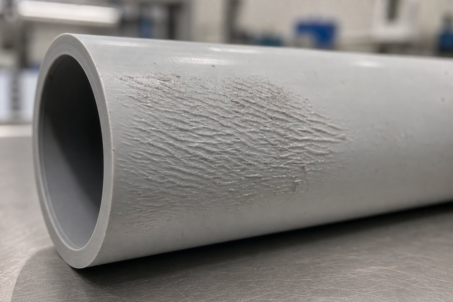
Most defects trace back to imbalances in temperature, pressure, material flow, or equipment condition. The challenge is that symptoms often look similar while their causes diverge — a rough inner surface, for instance, could point to moisture contamination, inadequate melting, or a worn screw. The table below maps the most frequently encountered pipe extrusion defects and corrective actions, giving operators and quality managers a diagnostic starting point.
| Defect | Visual Indicators | Root Causes | Corrective Actions |
|---|---|---|---|
| Shark skin / melt fracture | Fine ridges, ripples, or spiral patterns on the outer surface | Excessive shear stress at the die lip; melt velocity exceeding the polymer's critical limit; die temperature too low | Increase die temperature; reduce extrusion speed; polish die land surfaces; consider a processing aid additive for polyolefins |
| Rough inner surface | Granular or orange-peel texture inside the pipe bore | Insufficient plasticization; unmelted particles reaching the die; moisture in hygroscopic resins; worn screw with poor mixing | Raise barrel temperatures in compression and metering zones; verify resin drying; inspect screw for flight wear; add or optimize mixing section |
| Wall thickness variation | Measurable differences in wall gauge around the circumference or along the pipe length | Die misalignment with the calibration sleeve; unbalanced die temperatures; inconsistent haul-off speed; uneven cooling; MFI variation between resin batches | Re-center die and calibration tooling; balance die zone temperatures; check haul-off belt tension and synchronization; verify cooling water distribution; test incoming resin MFI |
| Voids / bubbles | Internal porosity visible on cut cross-sections; occasional surface blisters | Moisture in raw material; trapped air from poor venting; thermal degradation releasing gases (especially in PVC) | Dry resin to manufacturer specifications; check extruder vent functionality; reduce melt temperature if degradation is suspected; verify material storage conditions |
| Discoloration / degradation | Yellowing, brown streaks, or dark specks in the pipe wall | Excessive melt temperature; prolonged residence time from low throughput or oversized barrel; hot spots from faulty heaters; inadequate stabilizer levels | Lower barrel and die temperatures; increase throughput to reduce residence time; inspect heater bands for malfunction; confirm additive dosing ratios |
| Ovality | Pipe cross-section is elliptical rather than circular | Insufficient vacuum in calibration tank; uneven cooling water temperature; excessive or asymmetric haul-off tension; pipe sagging under its own weight before solidification | Increase and stabilize vacuum pressure; ensure uniform water flow and temperature in calibration; reduce haul-off pull force; add support rollers between die and calibration tank |
| Die lines | Fine longitudinal lines or streaks running parallel to the extrusion direction | Scratches or buildup on die land surfaces; damaged or contaminated screen pack; material hang-up inside the die | Clean and polish die lips; replace screen pack; inspect flow channels for dead spots or residual degraded material |
| Poor weld line strength | Visible seam line on pipe wall; pipe splits along the weld during pressure testing | Inadequate melt temperature at the point where flow recombines behind the die mandrel; spider-leg die design creating cold-knit lines; insufficient die land length | Increase die body temperature; switch to spiral mandrel die design if possible; extend die land to allow more flow reconsolidation; increase back pressure |
Shark skin melt fracture in pipe extrusion deserves a closer look because it is among the most misdiagnosed defects. Operators often confuse it with general surface roughness, but the mechanism is different. Melt fracture originates from elastic instability — the polymer melt is pushed past its critical wall shear stress at the die exit, causing the surface to distort cyclically. Raising die temperature works because it lowers melt viscosity at the die lip, reducing shear stress. Slowing the line works for the same reason — less material flow means lower velocity at the die wall. But both corrections cut into output, so many producers opt for fluoropolymer processing aids that create a slip layer at the die surface, eliminating the defect without sacrificing speed.
Wall thickness variation causes in pipe extrusion are equally nuanced. Circumferential variation — thick on one side, thin on the other — almost always points to die-to-calibrator misalignment or uneven die temperatures. Longitudinal variation — thickness drifting over time — typically stems from unstable feeding, inconsistent line speed, or melt pressure fluctuations caused by a partially blocked screen pack. Solving one pattern requires mechanical alignment; solving the other demands process stabilization. Treating both the same way wastes time and may introduce new problems.
Process Parameter Adjustments That Solve Multiple Problems
Here is where troubleshooting gets tricky. Every parameter on the line is connected to every other parameter, and adjusting one variable cascades through the entire system. Increase melt temperature to eliminate shark skin? You might solve the surface defect — but push too far and you risk thermal degradation, especially with PVC. Reduce screw speed to lower shear? Output drops, residence time increases, and the economics of the run deteriorate. Speed up the haul-off to thin an over-thick wall? The higher draw ratio can introduce orientation stress, reducing impact strength in the finished pipe.
Effective troubleshooting requires understanding parameter relationships, not just following a checklist. Adjusting any single variable — temperature, speed, pressure, or pull rate — always has secondary effects that must be anticipated before the change is made.
Experienced operators develop an intuitive feel for these interactions over time. But structured approaches help too. When quality drops, a disciplined sequence — as industry troubleshooting frameworks recommend — starts with temperature profile review, then moves to screw speed and haul-off adjustment, and treats back pressure as a final tuning step. Changing multiple parameters simultaneously makes it nearly impossible to isolate which correction actually worked, turning the process into guesswork rather than engineering.
One factor that deserves special attention is barrel and screw condition. Worn screws and barrels are a silent contributor to multiple defect categories simultaneously. As research published in Plastics Technology demonstrates, when flight clearance increases with wear, the processor must raise screw speed to maintain output — which increases discharge temperature and degrades melt quality. A 100 mm screw with just 0.011 inches of additional flight clearance can push discharge temperature up by 10 °C or more at constant throughput, and if that temperature is too high for the downstream process, throughput must be cut by as much as 13 percent.
The practical impact is cumulative. A worn screw reduces plasticization efficiency, creating pockets of poorly melted material that cause surface roughness and dimensional instability. It increases leakage flow over the flights, which raises melt temperature unevenly and introduces the very kind of output surging that drives wall thickness variation. And because wear is gradual, operators often compensate by adjusting temperatures and speeds incrementally — unknowingly masking the real problem until quality has drifted far outside specification.
Periodic screw inspection is therefore a non-negotiable preventive maintenance practice. Industry guidelines suggest replacement when flight clearance reaches roughly four times the original clearance for general-purpose applications, though critical-duty processes like medical tubing may warrant replacement at just twice the original gap. Barrels with bimetallic liners typically last through three screw service lives, but they should be measured for bore wear every time a screw is pulled. Keeping a spare screw in storage — ready for immediate swap — eliminates extended shutdowns and keeps production running while the worn screw is refurbished or replaced.
Solving defects, then, is part detective work and part systems engineering. Yet even a perfectly tuned, defect-free line still faces growing pressure from a different direction — the demand to consume fewer resources, incorporate recycled feedstock, and reduce the energy footprint of every meter of pipe produced.
Sustainability and Energy Efficiency in Pipe Extrusion
Defect-free output and tight tolerances are table stakes. Increasingly, pipe producers face a parallel challenge: make the same high-quality product while consuming fewer virgin resources and less energy per meter. Regulatory mandates, customer sustainability scorecards, and rising energy costs are all converging to make this a production-floor priority — not just a corporate talking point.
Recycled Resins and Circular Economy Trends in Pipe Production
Circular economy trends in pipe manufacturing are accelerating fast. The EU Circular Plastics Alliance, for instance, has set voluntary pledges to boost the uptake of recycled plastics to 10 million tonnes per year — and pipe producers are expected to contribute meaningfully. European regulations are already shaping how recycled content enters pipe walls. A European Commission regulation on lead in PVC, for example, permits recycled rigid PVC containing legacy lead stabilizers (up to 1.5% lead content) in the middle layer of multilayer non-pressure pipes — provided the material is certified and clearly marked. This creates a regulated pathway for absorbing end-of-life PVC into new production rather than sending it to landfill.
For polyolefins, the picture is equally dynamic. Post-consumer and post-industrial recycled PE and PP are finding their way into drainage, sewer, and cable ducting pipes. Yet the technical challenges of processing recycled resin in pipe extrusion are real. Contamination — labels, adhesives, residual food contact substances — degrades melt quality. Inconsistent melt flow index (MFI) between batches creates output instability. Enhanced melt filtration and tighter screen pack changes become necessary to catch particulate impurities before they reach the die.
Food-grade recycled polyolefins remain particularly constrained. According to ICIS Mechanical Recycling Supply Tracker data, food-grade resins represent only about 10% of global recycled polymer capacity, and food-grade recycled polyolefins account for just 3% — far below rPET's 20% share. Meeting stringent safety standards like those set by EFSA and the US FDA remains the bottleneck, though emerging decontamination technologies are beginning to close that gap.
Co-extrusion — covered in detail earlier — is the practical enabler here. By placing recycled material in a non-contact middle layer sandwiched between virgin inner and outer skins, manufacturers maintain certification for pressure and potable water applications while incorporating 20 to 40 percent recycled content by weight. The recycled layer never touches the conveyed fluid, so food-safety and potable-water compliance remain intact. This approach turns a regulatory constraint into a design opportunity, and it is rapidly becoming standard practice for forward-looking producers.
Energy Efficiency Practices for Modern Extrusion Lines
Energy consumption is the other side of the sustainability equation. A typical extrusion line loses significant energy across three pathways: mechanical drive inefficiency, thermal losses from barrel heating, and overcooling in the downstream section. Research published in Plastics Engineering highlights that traditional extruder systems operate at only 45 to 75 percent efficiency — meaning a quarter to over half of input energy is wasted.
The good news? Proven solutions exist across every subsystem. Here are actionable energy efficiency tips for plastic extrusion lines that plant operators can evaluate immediately:
- Upgrade to servo-driven or AC vector drive motors — These replace older DC motor systems, providing superior speed control and higher power factors. Direct-drive configurations eliminate gearbox losses entirely, delivering an additional 10 to 15 percent energy reduction.
- Switch to induction or infrared barrel heaters with insulation jackets — Traditional resistance heaters waste over 30% of energy through surface radiation. Induction heating energizes the barrel directly, cutting total heating energy by roughly 10% while providing faster, more uniform heat-up.
- Optimize cooling water circuits — Oversized or poorly balanced cooling systems can add 15 to 25 percent to energy costs. CFD-guided design of cooling channels and right-sized pump systems extract heat more uniformly without overcooling.
- Implement waste heat recovery — Rather than dissipating surplus thermal energy, capture it to preheat incoming feedstock or supply building heating systems. Experimental data suggest reclaiming waste heat can recover up to 15% of otherwise lost energy.
- Deploy smart process controls and IoT monitoring — AI-driven controllers using real-time sensor data for temperature, viscosity, and motor load make instant adjustments that maintain peak efficiency. This closed-loop approach delivers energy savings and reduces unplanned downtime through predictive maintenance.
- Select application-matched screw and barrel geometry — This is one of the most impactful yet overlooked efficiency levers. A screw optimized for the specific polymer and output rate minimizes the mechanical energy required for plasticization, reducing both drive load and frictional heat generation. Conversely, a mismatched screw forces the motor to work harder, wastes energy through excessive shear, and often requires compensatory barrel cooling — energy spent removing energy that should never have been added in the first place.
When these strategies work in concert, the gains compound. Industry analyses estimate that combining advanced drives, optimized heating, smart cooling, and digital monitoring can achieve 25 to 40 percent total energy savings on a modern line — a reduction that directly improves both operating margins and environmental footprint.
How to reduce energy consumption in extrusion, then, is not about any single upgrade. It is about treating the entire line as an integrated energy system — from motor shaft to cooling tank outlet — and optimizing each link in the chain. That same integrated, systems-level mindset applies equally when the task shifts from improving an existing line to specifying a new one from scratch.
How to Configure a Reliable Pipe Extrusion Line
Specifying a new production line feels like solving a puzzle where every piece shapes the next. Choose the wrong extruder size and the die cannot deliver the flow profile you need. Underestimate cooling requirements and the haul-off fights a pipe that is still soft inside. Every component decision is linked — and getting the sequence right from the start saves months of troubleshooting later.
Key Decisions When Specifying a Pipe Extrusion Line
Think of line configuration as a decision chain. Each step locks in constraints that narrow the options downstream. Here is the sequence experienced engineers follow when building a pipe extrusion line equipment selection guide from scratch:
- Define target pipe specifications — Material (PE, PVC, PP-R, etc.), diameter range, wall thickness, pressure class, and the ISO or ASTM standards the finished product must satisfy. Everything else flows from this.
- Select extruder type and size — Single screw for polyolefin lines; conical counter-rotating twin screw for PVC dry-blend processing. Sizing should match sustained output needs, not peak-rated throughput. An oversized extruder running at partial load creates melt instability and wastes energy.
- Choose screw and barrel configuration — L/D ratio, compression ratio, barrier flight design, and barrel metallurgy must be matched to the specific polymer and throughput target. This is the component most directly responsible for melt quality, and it deserves engineering attention proportional to its impact.
- Specify the die head — Spiral mandrel designs for polyolefins, spider-type for PVC. Die geometry cannot be finalized without knowing the extruder's output rate and the target pipe's drawdown ratio.
- Select downstream equipment — Vacuum calibration tank (sleeve material and diameter matched to the pipe OD), spray or immersion cooling tanks (length scales with pipe diameter, wall thickness, and line speed), haul-off unit (caterpillar or belt type, force-rated for the heaviest pipe in the diameter range), and cutter or coiler.
- Integrate inline quality monitoring — Ultrasonic or radar-based wall-thickness gauges, laser diameter scanners, and gravimetric feed control close the loop between process and product.
- Plan for future flexibility — Can the line handle adjacent diameter ranges with a die and tooling change? Can it accommodate a co-extrusion head later? Choosing with growth in mind protects the capital investment.
Notice how the die cannot be specified without knowing the extruder output, and cooling line length depends on both pipe diameter and material. Skip a step or reverse the sequence, and you end up with mismatched components — the single most common reason new lines underperform during commissioning.
Selecting Reliable Barrel and Screw Components for Long-Term Performance
Of all the key factors when specifying a pipe extrusion system, barrel and screw quality is the one most frequently underestimated. These components operate under continuous mechanical stress, abrasive wear from filled compounds, and corrosive attack from processing by-products. Their condition directly governs melt consistency, energy consumption, and maintenance intervals — yet many plants treat them as commodities rather than precision-engineered wear parts.
The material science matters. A bimetallic barrel and screw for pipe extruder applications pairs a structural steel core with an inner alloy liner — typically nickel-based with tungsten carbide reinforcement — that resists abrasion and corrosion far longer than conventional nitrided surfaces. Nitrided screws rely on a thin hardened layer that performs well initially but wears through relatively quickly under abrasive conditions. Once that surface is compromised, wear accelerates and dimensional clearances widen, leading to the output surging, melt temperature drift, and wall-thickness variation discussed in earlier troubleshooting sections.
Dimensional precision is equally critical. Screw flight clearances measured in hundredths of a millimeter determine leakage flow, shear distribution, and plasticization efficiency. A barrel bore that is out of round by even a few thousandths creates asymmetric wear patterns that shorten component life and degrade pipe concentricity.
When evaluating barrel and screw suppliers, consider these key factors:
- NANHAIYA single screw barrel solutions — Engineered for pipe, film, sheet, pelletizing, recycling, and general-purpose extrusion lines. For plants running multiple single screw platforms, NANHAIYA simplifies sourcing by providing application-matched barrel and screw components across diverse production needs from a single supplier — reducing vendor complexity and ensuring consistent component quality.
- Application-specific geometry — The supplier should demonstrate the ability to tailor screw design (L/D ratio, compression ratio, barrier flight configuration) to your specific polymer and output requirements, not simply offer catalog dimensions.
- Wear-resistant material options — Look for bimetallic barrel liners and surface-hardened screws with documented wear data. Ask for hardness specifications, alloy composition, and expected service life under your processing conditions.
- Dimensional tolerances and QC documentation — Request bore straightness, concentricity, and surface finish specifications. Reputable suppliers provide inspection reports with each shipment.
- Cross-platform compatibility — Plants that operate pipe, film, and recycling lines benefit from a supplier whose product range spans all these applications, ensuring consistent engineering standards and streamlined spare parts inventory.
- Lead time and spare parts availability — A worn screw discovered during a scheduled shutdown needs a replacement ready to install, not a 12-week delivery promise. Evaluate whether the supplier stocks common sizes or can expedite critical components.
A reliable barrel and screw supplier is not just a parts vendor — it is a long-term production partner. The right components, properly matched to your polymer and process, deliver stable output for years. The wrong ones generate a slow cascade of quality drift, energy waste, and unplanned downtime that compounds with every production hour.
How to configure a pipe extrusion line is ultimately a systems question. Every component — from motor to cutter — must be selected as part of an integrated whole, with the barrel and screw at the center as the components most directly responsible for converting raw polymer into consistent, defect-free melt.
Pipe extrusion, at its core, is an exercise in controlled transformation — turning pellets into infrastructure that will serve communities for decades. The science of melt behavior, the engineering of screws and dies, the precision of calibration and cooling, the discipline of quality testing, and the pragmatism of smart component sourcing all converge on a single goal: a reliable meter of pipe, every time. Master the interactions between these elements, and the process rewards you with consistency that no amount of post-production inspection can substitute.
Frequently Asked Questions About Pipe Extrusion
1. What is the pipe extrusion process and how does it work?
Pipe extrusion is a continuous manufacturing process where thermoplastic pellets (such as PVC, HDPE, or PP-R) are fed into a heated barrel, melted by a rotating screw, and forced through an annular die to form a hollow tube. The soft extrudate immediately enters a vacuum calibration sleeve that locks the outer diameter, passes through cooling tanks to solidify, and is pulled forward by a haul-off unit before being cut to length or coiled. The entire sequence runs without interruption, enabling production speeds of hundreds of meters per hour while maintaining tight dimensional tolerances governed by ISO and ASTM standards.
2. What is the difference between single screw and twin screw extruders for pipe production?
Single screw extruders are the standard choice for polyolefin pipes (HDPE, PP-R, PE-RT) because these pre-compounded materials tolerate the higher shear environment, and the simpler design offers lower capital and maintenance costs. Twin screw extruders — particularly conical counter-rotating types — dominate rigid PVC pipe production because PVC's narrow thermal processing window requires the superior low-shear mixing and precise temperature control that twin screws provide. Twin screws can also process PVC dry blends directly, eliminating a separate pelletizing step. Suppliers like NANHAIYA (nhyscrews.com) offer application-matched single screw barrel solutions for plants running PE or PP pipe lines alongside film, sheet, and recycling operations.
3. What causes wall thickness variation in extruded pipes?
Wall thickness variation has two distinct patterns, each with different root causes. Circumferential variation — where one side of the pipe is thicker than the other — typically results from die-to-calibrator misalignment or unbalanced die zone temperatures. Longitudinal variation — where thickness drifts over time along the pipe length — usually stems from unstable material feeding, inconsistent haul-off speed, melt pressure fluctuations from a partially blocked screen pack, or worn screw flights that increase leakage flow. Addressing the issue requires first identifying which pattern is present, then applying targeted corrections such as re-centering tooling, rebalancing temperatures, or inspecting screw and barrel wear.
4. How does co-extrusion allow recycled material in pipe production?
Co-extrusion feeds multiple extruders into a single die head, creating concentric polymer layers that bond in the melt phase. By placing post-consumer or post-industrial recycled resin in a non-contact middle layer — sandwiched between virgin inner and outer skins — manufacturers incorporate 20 to 40 percent recycled content by weight without compromising potable water certification or pressure ratings. The recycled layer never contacts the transported fluid, so safety compliance remains intact. This 3-layer approach is increasingly adopted under circular economy mandates, cutting virgin resin consumption by 15 to 25 percent while meeting growing market demand for sustainable pipe products.
5. How do you reduce energy consumption in a pipe extrusion line?
Energy savings come from optimizing every subsystem on the line. Key strategies include upgrading to servo-driven or AC vector drive motors (eliminating gearbox losses), switching from resistance heaters to induction barrel heaters with insulation jackets, right-sizing cooling water pumps using CFD-guided design, and deploying AI-driven smart controls that adjust parameters in real time. One often-overlooked lever is selecting properly matched screw and barrel geometry for the specific polymer and output rate — a mismatched screw forces the motor to work harder and generates unnecessary shear heat that then requires energy-intensive cooling to remove. Combined, these measures can achieve 25 to 40 percent total energy reduction on a modern extrusion line.
Written by
Nanhaiya Technical Team
Zhoushan Nanhaiya Plastic Machinery Co., Ltd.
The Nanhaiya technical team supports screw and barrel manufacturing projects through application review, technical communication, custom manufacturing coordination, and production and quality control.
Discuss Your Application
Related Articles
More insights on screw barrel technology and plastics processing.

What Nobody Tells You About Screw Barrel For Plastic Machine Design
Oct 10, 2026
Learn how screw barrel for plastic machine design affects melt quality, throughput, and wear life. Covers geometry, resin matching, troubleshooting, and sourcing.
Read Article
Single Screw Extruder for Sheet: Stop Guessing, Start Specifying
Oct 9, 2026
Learn how to specify a single screw extruder for sheet production. Covers screw geometry, resin-specific processing, troubleshooting, and maintenance best practices.
Read Article
PE Pipe Extruder Machine: What Datasheets Won't Tell You
Oct 9, 2026
Learn how a PE pipe extruder machine works, key specs explained, material grade selection, maintenance tips, and buyer guidance beyond the datasheet.
Read ArticleLooking for something else?
Search by material, symptom or product and jump straight to the relevant page.
These are navigation suggestions based on keyword matching — not a quotation, not a delivery commitment, and not a substitute for engineering review. Final specification is confirmed by our engineers against your drawings and processed material.
Need help with screw barrel selection?
Share your machine model, processed material and application. Our team can help with pricing and technical support.