

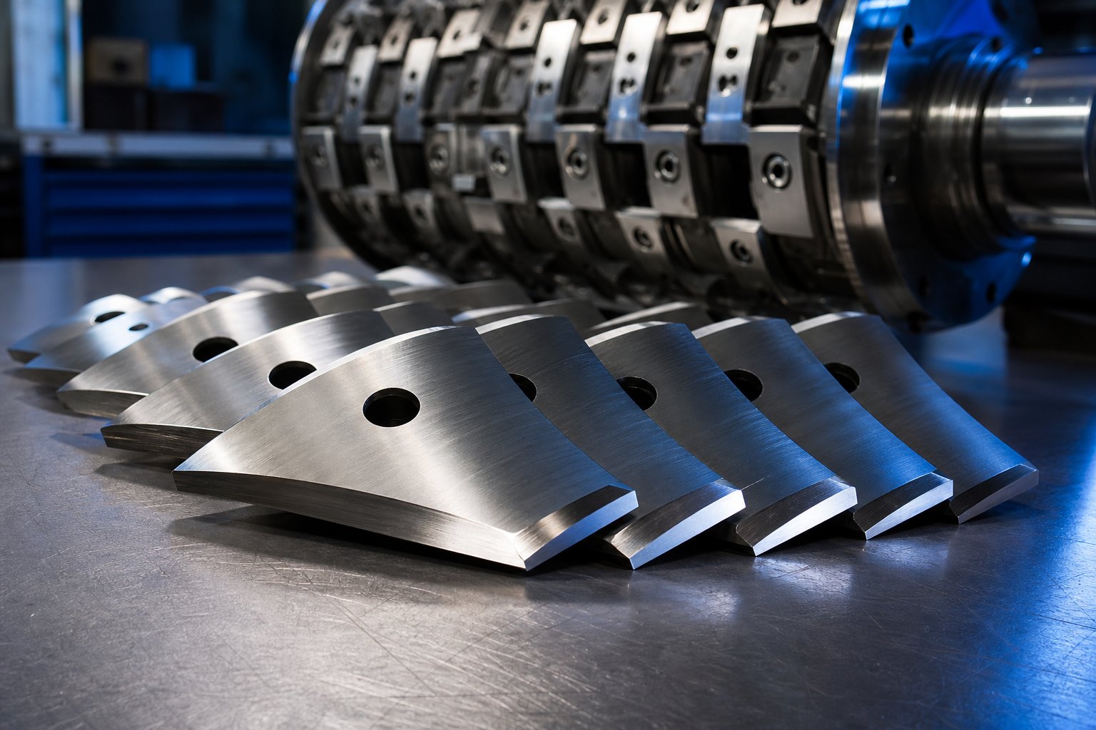
What Pelletizing Blades Do and Why They Matter
Every plastic pellet you've ever seen — those small, uniform granules fed into injection molding machines, blown film lines, and sheet extruders — was shaped by a single cutting event. That event depends entirely on one component: the pelletizing blade. When this tool performs well, production hums along unnoticed. When it doesn't, the evidence shows up fast — in misshapen pellets, clogged feed throats, and frustrated operators.
What Is a Pelletizing Blade
A pelletizing blade is a precision-ground cutting tool mounted on a high-speed rotor that shears molten or cooled polymer strands against a die plate face, producing uniform plastic pellets for downstream processing.
That definition captures the core function, but there's more to unpack. These blades operate in extrusion and compounding lines where polymers are melted, mixed, and pushed through a perforated die plate. As the material exits the die holes — either as molten strands or cooled solid ropes — the rotating blade sweeps across the die face and severs each strand into a discrete pellet. The blade's edge geometry, material hardness, and mounting precision all influence the final pellet's shape, size, and surface quality.
Think of it this way: the extruder and die plate determine what comes out, but the pelletizing blade determines how cleanly it's cut.
Why Blade Quality Matters in Polymer Processing
A dull, chipped, or improperly set blade doesn't just produce ugly pellets. It creates a cascade of downstream problems. Poor cuts generate defects that pellet processors know all too well — tails, longs, doubles, angel hair, and fines. These irregularities cause real operational headaches: bridging in hoppers, inconsistent feeding in injection molding machines, and poor dispersion in film extrusion. Davis-Standard identifies at least 13 distinct pellet defects traceable to cutting-system issues, many rooted in blade condition.
For maintenance teams, plant buyers, and machine rebuilders, understanding how a pelletizing blade works — and how it fails — is essential knowledge. It directly impacts product quality, machine uptime, and operating costs.
This article covers the full picture: cutting mechanics inside the pelletizer head, blade types matched to each pelletizing process, the material science behind steel and carbide options, wear-pattern diagnostics, die plate interface management, lifecycle best practices, and smart sourcing strategies. Each section is designed to help you make better decisions about the blades your operation depends on.
How Pelletizing Blades Work Inside the Cutting Chamber
Imagine a lawnmower spinning against a flat surface full of tiny holes, each one pushing out a thin thread of melted plastic. That's essentially what's happening inside a pelletizer head — except the tolerances are measured in thousandths of an inch, the rotor spins at hundreds or thousands of RPM, and the result needs to be thousands of perfectly identical pellets every minute. Understanding pelletizer cutting chamber mechanics starts with knowing what's inside that housing and how each component contributes to a clean cut.
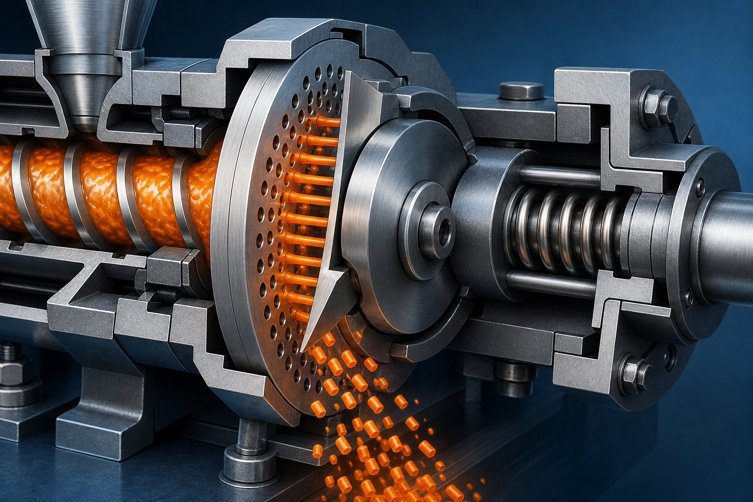
Anatomy of the Blade-Rotor-Die Assembly
The pelletizer rotor blade assembly consists of several tightly integrated components, each with a specific role. Here's how they work together:
- Die plate: A heated steel disc with dozens to hundreds of precision-drilled holes through which molten polymer is extruded. The front face is lapped flat to provide a smooth cutting surface for the blades.
- Pelletizer rotor (hub): A machined disc or spider that bolts to the motor-driven shaft. It provides the mounting platform for all blade stations and must be dynamically balanced to prevent vibration at high speeds.
- Blade holders: Slots or clamps machined into the rotor that secure each pelletizing blade at the correct angle and radial position. Designs vary — some use dovetail slots, others use bolted clamping bars.
- Adjustment screws or shims: Allow fine-tuning of individual blade height so every cutting edge sits at the same plane, ensuring all stations make uniform contact with the die face.
- Spring or hydraulic pressure system: Pushes the entire rotor assembly forward against the die plate, maintaining intimate blade-to-die contact. Too much pressure accelerates wear; too little leaves strands uncut, producing tails and doubles.
You'll notice that no single part works in isolation. The spring pressure holds the blades against the die face, while the rotor's rotation generates centrifugal force that can also influence blade seating in certain designs. Every element must be in spec for the system to produce consistent pellets.
The Cutting Mechanics Behind Uniform Pellets
So how do pelletizing blades cut polymer strands cleanly? The answer lies in a shearing action — not a crushing one. As molten polymer emerges from each die hole, the blade's sharp edge sweeps across the die face and slices the strand at a precise length. A clean shear leaves a smooth pellet surface. A dull or poorly seated blade, by contrast, smears the soft polymer rather than severing it, creating deformed pellets with ragged edges.
The relationship between blade tip speed and pellet length is straightforward but critical. Pellet length is determined by this interaction:
Pellet length = Extrusion rate per hole / (Number of blade stations x Rotor RPM)
In practical terms, increasing rotor speed or adding more blade stations shortens each pellet. Reducing either produces longer pellets. A four-blade rotor spinning at 3,000 RPM makes 12,000 cuts per revolution cycle per minute — and every one of those cuts needs to be identical. If one blade sits even slightly proud or recessed relative to the others, you'll get alternating long and short pellets in the product stream.
Blade tip speed — the linear velocity of the cutting edge as it sweeps the die face — typically ranges from 5 to 25 m/s depending on the pelletizer design and polymer being processed. Higher tip speeds produce cleaner cuts on soft, high-MFI melts that would otherwise smear. Lower tip speeds suit stiffer, already-cooled strands in strand pelletizers where excessive speed generates dust and fines.
This interplay between rotor speed, blade count, die hole configuration, and polymer rheology is what makes pelletizer setup more art than formula — and it's why blade geometry and material choice deserve their own detailed discussion.
Pelletizing Blade Types for Every Process Method
Not all pelletizing blades are created equal — and they shouldn't be. The polymer leaving a die plate can be a molten thread surrounded by rushing water, a cooled solid strand dragged across a conveyor, or a hot bead sliced in open air. Each scenario demands a different blade profile, a different material, and a different approach to wear management. Choosing the wrong type for your process is like fitting a bread knife where a scalpel belongs. It might cut, but the results won't be pretty.
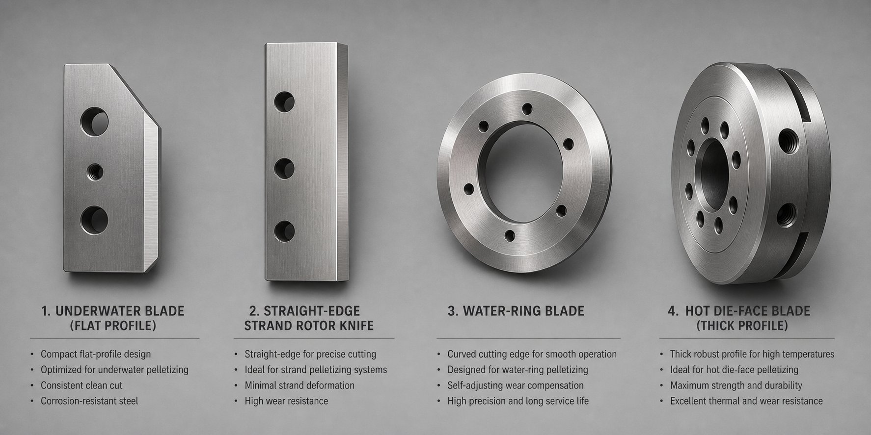
The types of pelletizing blades by process method break down into four primary categories: underwater, water-ring, strand, and hot die-face. Each one reflects the unique physics of its cutting environment. Let's walk through them.
Underwater Pelletizer Blades
Underwater pelletizing — often abbreviated UWP — is the premium method for producing perfectly round, uniform pellets at high throughput. Picture this: molten polymer exits the die holes directly into a water-filled chamber, and blades spinning at high speed shear the melt strands right at the die face while submerged. The water instantly cools and solidifies each pellet into a smooth, spherical shape before it's carried away through a slurry line.
This environment puts extraordinary demands on the blade. The cutting edge contacts the die plate face with precision spring or hydraulic pressure while fully immersed in circulating process water — often treated but never perfectly clean. That combination creates two critical challenges:
- Corrosion resistance: Constant water exposure, especially at elevated temperatures (process water typically runs between 50-80°C), can attack standard tool steels. Stainless grades or specialized coatings become essential.
- Thermal shock tolerance: The blade face contacts polymer melt exceeding 200°C on one side while the opposite surface sits in cooling water. This repeated thermal cycling can cause micro-cracking in brittle materials.
Underwater pelletizer blade specifications also reflect geometric constraints. These blades are typically compact, flat-profile cutters designed to ride flush against the die face with minimal overhang. They're mounted in multi-station rotors — commonly four, six, or eight blade positions — and must be ground to extremely tight flatness tolerances so every station contacts the die uniformly.
Major UWP system manufacturers like Gala (now part of Maag), Nordson BKG, and Maag each use proprietary rotor and blade-holder designs, but the fundamental blade geometry is similar across platforms. Aftermarket blades manufactured to match OEM dimensions and materials can serve as direct replacements, provided they meet the same flatness, hardness, and surface finish specifications.
Strand Pelletizer and Water-Ring Blades
Strand pelletizers work on an entirely different principle. Instead of cutting molten polymer at the die face, the process extrudes continuous strands through the die, cools them in a water bath or on a cooling conveyor, and then feeds the solidified strands into a separate cutting unit downstream. The blade here isn't shearing soft melt — it's chopping through a cooled, semi-rigid rope of plastic.
This changes the blade profile significantly. Strand pelletizer blades — sometimes called rotor knives — typically feature a straight or slightly helical cutting edge mounted on a cylindrical rotor. They work in conjunction with a stationary bed knife, creating a scissor-like shearing action as each strand passes between the two edges. The strand pelletizer blade vs die face blade distinction is fundamental: strand blades need high impact toughness to handle the mechanical shock of cutting solid material, while die-face blades prioritize wear resistance and flatness for continuous melt contact.
Key characteristics of strand pelletizer blades include:
- Longer cutting edges: They span the full width of the strand bundle, which can be 300 mm or more across.
- Helical geometry options: Some rotors use a slight helix angle on the blade edge to create a progressive, shearing cut that reduces cutting force and noise.
- Lower rotational speeds: Strand cutters typically spin slower than die-face pelletizers, but the cutting forces per impact can be higher due to the solid-state material.
Water-ring pelletizers sit somewhere between strand and underwater systems. The molten polymer is cut at the die face — like in underwater pelletizing — but instead of full submersion, a ring of water around the die periphery cools and transports the pellets. Water ring pelletizer blade geometry closely resembles underwater blades in profile, but the cooling environment is less aggressive, and the blades may not need the same level of corrosion resistance. These systems are popular for polyolefins like PE and PP films, offering a practical balance of pellet quality and equipment simplicity.
Hot Die-Face Pelletizer Blades
Hot die-face pelletizing — also called dry-cut or air-quench pelletizing — takes the most direct approach. Blades cut the molten polymer right at the die face, just like in underwater systems, but there's no water. The pellets are severed in open air and then cooled downstream, either on a vibrating conveyor or in a fluidized bed.
Without water to absorb heat, the blade operates in an extremely hot environment. Die face temperatures can exceed 300°C for engineering resins, and the blade's cutting edge is in near-continuous contact with that heated surface. This makes hot die face pelletizer blade material selection critical. Standard tool steels soften and lose their edge rapidly at sustained high temperatures. Processors running dry-cut systems typically turn to:
- High-speed steels (e.g., M2, M42): These retain hardness at elevated temperatures far better than cold-work steels like D2.
- Tungsten carbide tipped or full-carbide inserts: For the most demanding applications, carbide provides extreme heat and wear resistance, though at higher cost and with reduced toughness.
- Specialty coatings: Titanium nitride (TiN) or chromium nitride (CrN) coatings can add a thermal barrier and reduce friction against the die plate.
Hot die-face blades also tend to be thicker and more robust than their underwater counterparts, designed to absorb and dissipate heat without warping. Blade flatness is just as critical here — any deviation from the die plate surface creates gaps that produce tails or incomplete cuts.
Process Comparison at a Glance
Choosing the right blade starts with understanding which pelletizing process you're running. The table below puts all four methods side by side:
| Process Type | Blade Geometry | Typical Material | Key Challenge |
|---|---|---|---|
| Underwater (UWP) | Compact, flat-profile; multi-station rotor mount | Stainless steel (440C), coated tool steel, or carbide | Corrosion from process water and thermal shock cycling |
| Water-Ring | Similar to UWP; flat die-face contact design | Tool steel (D2) or stainless, depending on resin | Balancing wear resistance with moderate corrosion exposure |
| Strand | Straight or helical rotor knife paired with bed knife | D2 or high-speed steel (M2); carbide for abrasive resins | Impact toughness for cutting cooled, solid strands |
| Hot Die-Face (Dry Cut) | Thick, robust flat-profile; heat-resistant design | High-speed steel (M2, M42) or tungsten carbide | Sustained high temperatures causing edge softening and wear |
You'll notice that no single blade material or geometry dominates across all four methods. The underwater environment demands corrosion resistance above all. Strand systems prioritize toughness. Hot die-face setups require thermal stability. And water-ring systems need a practical compromise. Each process tells the blade what it needs to survive — and the blade material is what determines whether it actually does.
Blade Materials Explained From Tool Steel to Carbide
Supplier catalogs love to promise "premium materials" and "high-quality steel" without ever naming a specific grade, hardness range, or heat treatment protocol. That vagueness doesn't help you make real decisions. When a pelletizing blade fails prematurely, the answer almost always traces back to a mismatch between the material and the application — not some generic quality shortfall. So let's get specific.
The materials used in pelletizing blades fall into three broad families: conventional tool steels, advanced powder metallurgy (PM) steels, and cemented carbides. Each family offers a distinct balance of hardness, toughness, wear resistance, and corrosion resistance. Understanding these trade-offs is the difference between blades that last weeks and blades that barely survive a shift.
Tool Steel Grades for Standard Applications
Most pelletizing blades on the market today are made from tool steel — and for good reason. These steels provide a proven, cost-effective combination of edge retention and mechanical toughness that handles the majority of polymer processing scenarios. Three grades dominate the landscape:
- D2 (AISI D2 / SKD11): This is the workhorse. A high-chromium, high-carbon cold-work steel with roughly 12% chromium content, D2 delivers excellent wear resistance for general-purpose pelletizing. D2 tool steel pelletizing blade hardness typically falls between HRC 58-62 after proper heat treatment. It handles virgin polyolefins, ABS, polystyrene, and most unfilled engineering resins without issue. The limitation? D2's chromium carbides (M7C3 type) tend to be coarse and unevenly distributed in conventionally cast material, which creates stress-riser points under heavy impact. That's why D2 blades sometimes chip when processing abrasive or mineral-filled compounds.
- M2 (AISI M2): A high-speed steel containing tungsten, molybdenum, chromium, and vanadium, M2 excels where D2 falls short — elevated-temperature applications. The key advantage is "red hardness," meaning M2 retains its cutting edge at temperatures that would soften cold-work steels. If you're running a hot die-face pelletizer or processing polymers with high melt temperatures, M2 is a natural upgrade. Industry testing shows M2 blades lasting 40-60% longer than D2 in high-speed, high-temperature cutting applications. The trade-off is reduced toughness compared to D2, making M2 more susceptible to chipping under heavy contamination or impact loads.
- 440C (AISI 440C): A martensitic stainless steel that brings corrosion resistance into the equation. With roughly 17% chromium, 440C is the go-to choice for underwater pelletizing systems where constant water exposure would corrode conventional tool steels. It hardens to approximately HRC 58-60 and offers decent wear resistance — not as high as D2, but adequate for non-abrasive polymers in corrosive environments. Think of 440C as insurance against pitting and rust in wet-cutting applications.
Here's the critical detail that separates a good blade from a mediocre one made of the same steel: the pelletizing blade heat treatment process. Raw steel is just the starting point. The sequence of hardening (austenitizing and quenching), tempering (controlled reheating to relieve internal stresses), and — for premium applications — cryogenic treatment (deep-cooling to -120°C or lower to convert retained austenite into martensite) determines the blade's final performance characteristics. A D2 blade rushed through heat treatment might measure only HRC 55, wearing like mild steel. The same grade processed correctly hits HRC 60-62 with optimized carbide distribution.
Cryogenic treatment, in particular, deserves attention. By converting retained austenite — a softer, less stable phase — into martensite throughout the steel matrix, cryo processing improves dimensional stability and can extend blade life by 25% or more. It's not a marketing gimmick; it's metallurgy. If your supplier can't tell you their tempering temperature and whether they cryo-treat, that's a red flag.
Carbide and Advanced Powder Metallurgy Options
Standard tool steels meet their match when the polymer stream contains abrasive fillers. Glass fibers, mineral fillers like calcium carbonate or talc, and carbon fiber reinforcements act like sandpaper against the cutting edge. A D2 blade running glass-filled nylon might last days instead of weeks. That's where carbide and advanced PM steels come in.
Tungsten carbide (WC-Co) sits at the top of the wear-resistance hierarchy. A tungsten carbide pelletizer blade for abrasive polymers uses cemented carbide — tungsten carbide grains bonded with a cobalt binder — to achieve hardness values around HRA 93-94.5 (roughly equivalent to HRC 80+). This extreme hardness means carbide edges resist abrasive wear far longer than any steel. For steady-load applications on glass-filled or mineral-filled feedstocks, carbide typically delivers the lowest total cost of ownership despite its higher upfront price. The catch? Carbide is brittle. Under impact or misalignment, those hard edges chip rather than deform. Selecting higher cobalt content grades (K20-range) improves toughness somewhat, but carbide will never match the forgiveness of tool steel when contact conditions aren't perfect.
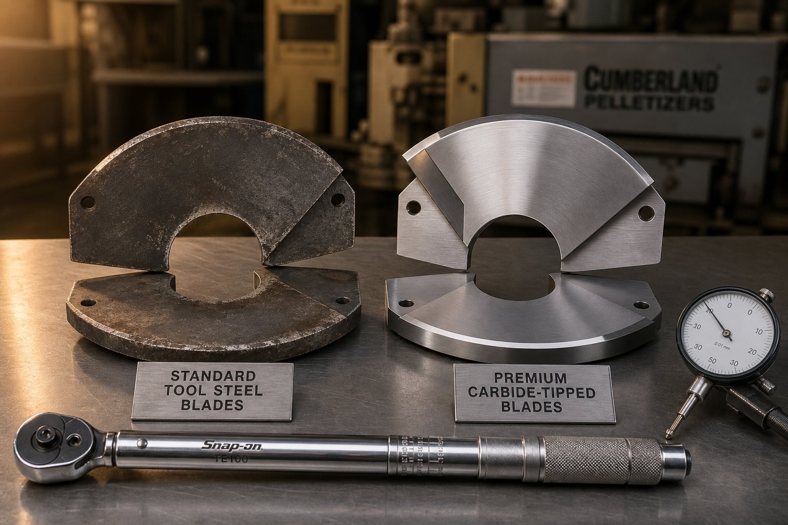
Pelletizing blades can use carbide in two configurations: carbide-tipped (a carbide insert brazed onto a steel blade body) or full-carbide construction. Tipped designs offer a cost-effective way to put carbide where it counts — at the cutting edge — while retaining a tougher steel body that absorbs vibration and mounting stresses. Full-carbide blades maximize wear life but require careful handling and precise die-plate flatness to avoid edge fracture.
CPM powder metallurgy steels occupy the sweet spot between conventional tool steel and cemented carbide. Grades like CPM-10V (AISI A11), CPM-9V, and CPM-M4 are produced through a powder metallurgy process that creates an extremely fine, uniform distribution of carbides throughout the steel matrix. Contrast this with conventionally cast D2, where carbides tend to cluster and create weak spots.
The CPM-10V vs D2 pelletizer blade wear resistance comparison is striking. CPM-10V's high vanadium content produces very hard vanadium carbides (VC type) that deliver abrasive wear resistance approaching carbide territory, while the PM microstructure provides significantly better toughness and chipping resistance than D2 at comparable hardness. CPM-10V can be heat-treated to HRC 62-64, and its fine carbide structure means the edge survives impacts that would fracture D2 or chip cemented carbide. In one documented field trial on 30% glass-filled PP, CPM-10V blades ran roughly 420 hours before needing their first regrind, while D2 blades required regrinding at just 160 hours — with significantly higher scrap rates from edge chipping.
CPM-9V trades a small amount of wear resistance for even greater toughness, making it an excellent choice where intermittent impacts from die plate irregularities or misfeeds are a concern. CPM-M4, a high-speed PM steel, adds superior hot hardness to the equation — ideal for hot die-face systems processing engineering polymers at elevated temperatures.
Polymer-Specific Material Selection
So which material is the best blade material for glass filled nylon pelletizing? What about PVC? Standard polyolefins? The answer depends on the specific wear mechanism your blades face. Here's the logic:
- Glass-filled polymers (PA6-GF, PA66-GF, PP-GF): Glass fibers are extremely abrasive. They grind down conventional steel edges rapidly. Carbide-tipped or full-carbide blades offer the longest life. CPM-10V provides a strong alternative when impact conditions make carbide too risky.
- Mineral-filled compounds (CaCO3, talc, BaSO4): Less aggressive than glass but still significantly more abrasive than unfilled resins. CPM-10V or carbide-tipped blades are smart upgrades over D2 for high-throughput lines.
- PVC (rigid and flexible): The primary enemy here isn't abrasion — it's corrosion. PVC processing releases hydrochloric acid (HCl) traces, especially at elevated temperatures. Stainless grades like 440C or corrosion-resistant coatings on tool steel blades are essential to prevent pitting and premature degradation.
- Standard polyolefins (PE, PP unfilled): These are relatively gentle on blade edges. D2 provides excellent service life at the best cost. There's rarely a reason to upgrade to carbide or PM steels unless throughput rates are extremely high or blade-change windows are very limited.
- Engineering resins at high melt temperatures (PET, PC, PEEK): Thermal softening of the blade edge becomes the primary concern. M2 or CPM-M4 high-speed steels retain their hardness at operating temperatures that degrade cold-work steels.
The table below puts all of this into a quick-reference format:
| Material | Hardness Range | Best For | Limitation |
|---|---|---|---|
| D2 Tool Steel | HRC 58-62 | Unfilled polyolefins, ABS, PS; general-purpose pelletizing | Chipping risk with abrasive fillers; limited corrosion resistance |
| M2 High-Speed Steel | HRC 60-65 | Hot die-face systems; high melt temperature resins (PET, PC) | Lower toughness than D2; higher cost; needs precise heat treatment |
| 440C Stainless Steel | HRC 58-60 | Underwater pelletizing; PVC and corrosive resin environments | Lower wear resistance than D2; not suited for abrasive fillers |
| CPM-10V (PM Steel) | HRC 62-64 | Glass-filled and mineral-filled polymers; high-throughput lines | Higher cost than D2; requires experienced heat treatment |
| CPM-9V (PM Steel) | HRC 54-58 | Abrasive resins with intermittent impact or misalignment risk | Lower maximum hardness; less wear resistance than CPM-10V |
| Tungsten Carbide (WC-Co) | HRA 93-94.5 | Highly abrasive glass/mineral-filled resins under steady load | Brittle under impact; high upfront cost; requires flat die plates |
Notice a pattern? There's no single "best" pelletizing blade material — only the best match for your specific polymer, filler profile, process type, and operating conditions. A blade that dominates on an unfilled polyethylene line might fail catastrophically on glass-filled nylon. The material decision is inseparable from the application context.
Yet even the perfect material choice can be undermined by something outside the blade itself. The interface where the cutting edge meets the die plate face introduces its own set of variables — contact pressure, gap settings, and die plate condition — that directly govern both pellet quality and how quickly that carefully selected edge wears away.
Blade-to-Die-Plate Interface and Gap Optimization
You could install the finest carbide pelletizing blade money can buy, heat-treated to perfection, and still destroy it within hours. How? By ignoring the surface it cuts against. The blade-to-die-plate interface is the single most influential contact zone in any die-face pelletizing system — underwater, water-ring, or dry-cut. It's where cutting actually happens, where wear concentrates, and where the earliest signs of trouble appear. Yet this critical interface receives surprisingly little attention in most maintenance programs.
Understanding how blade contact pressure affects pellet quality — and how die plate condition feeds back into blade longevity — transforms the way you approach pelletizer maintenance. Instead of reacting to bad pellets, you start preventing them.
Understanding Blade Contact Pressure and Gap Settings
In every die-face cutting system, the pelletizing blade must maintain intimate, continuous contact with the die plate face. This contact isn't passive. A spring-loaded or hydraulic mechanism behind the rotor assembly pushes the entire blade array forward against the die, and the force must be precisely controlled. Think of it as a controlled handshake — firm enough to make solid contact, gentle enough to avoid damage.
Here's what happens when that balance goes wrong:
- Too much pressure: The blade edge grinds aggressively against the die plate surface. Both components wear at accelerated rates. You'll see increased motor amperage, excessive heat generation at the die face, and premature blade edge rounding. In severe cases, the blade can gouge the die plate, creating grooves that become permanent quality problems.
- Too little pressure: The blade lifts slightly off the die face, leaving a micro-gap. Molten polymer exits the die holes and isn't cleanly severed — it stretches, smears, or only partially separates. The result is tails, twins, triplets, and chains that contaminate the pellet stream and create downstream feeding problems.
Pelletizer blade to die plate gap adjustment is typically measured in thousandths of an inch — a few mils at most. During startup, operators set the initial contact pressure according to the manufacturer's specifications, then fine-tune based on pellet quality. Some modern systems use automated pressure control with force sensors and feedback loops, but many production lines still rely on manual adjustment and operator experience.
Here's the complication: gap settings don't stay constant. As the blade edge wears during a production run, the effective contact geometry changes. A fresh blade sits flat and square against the die plate. After several hours of operation, edge rounding reduces the contact area, requiring either a pressure increase to compensate or a blade change to restore proper cutting. Experienced operators monitor observable signals — pellet shape, motor amperage trends, and visual inspection of cut quality — to decide when the drift has gone too far.
Imagine running your finger across a freshly sharpened kitchen knife versus one that's been used for months. The dull knife requires more force to cut — and the result is still worse. The same principle governs pelletizer blade contact, except the consequences include scrap pellets, unplanned shutdowns, and damaged die plates that cost thousands of dollars to resurface.
Die Plate Condition and Its Impact on Blade Life
Here's a truth many maintenance teams learn the hard way: a worn die plate will destroy new blades faster than any polymer ever could. The die plate face is the anvil against which every cut occurs. If that surface is grooved, scored, warped, or thermally distorted, even a perfectly ground blade cannot maintain uniform contact.
The failure mechanism is straightforward. A die plate develops wear grooves — shallow channels worn into the surface by thousands of hours of blade contact. Those grooves create alternating zones of contact and no-contact across the die face. In the grooved areas, the blade rides free and can't cut. In the raised areas between grooves, contact pressure concentrates, accelerating localized wear on both the blade and the die plate. The synchronization between die and blade that produces clean, uniform pellets depends entirely on this surface integrity.
Thermal distortion adds another layer of complexity. Die plates operate at elevated temperatures — often 200-300°C — and even small temperature gradients across the plate face can cause measurable warping. A plate that measures perfectly flat at room temperature may develop a concave or convex bow at operating temperature, lifting the blade off portions of the die face. This is particularly problematic in larger-diameter dies where thermal mass varies between the center and the perimeter.
Die plate resurfacing intervals for pelletizers vary by application, but a practical rule of thumb is to inspect the die face flatness every time you change blades — and to resurface when flatness deviation exceeds 0.001 to 0.002 inches across the cutting surface. Resurfacing involves precision lapping or grinding the die face back to a flat, mirror-like finish. Skipping or delaying this step to save time creates a vicious feedback loop: uneven die surfaces cause uneven blade wear, which further scores the die plate, which accelerates the next set of blades' degradation. Each cycle compounds the damage.
So what does improper blade-to-die contact actually look like in practice? Experienced operators learn to read the symptoms before they escalate. Watch for these warning signs:
- Pellet tails: Thin, hair-like polymer strands attached to pellets — the classic indicator that the blade isn't making clean contact across the full die face.
- Dust and fines generation: Excessive fine particles in the pellet stream suggest the blade is scraping or crushing rather than shearing cleanly, often caused by a dull edge combined with excessive contact pressure.
- Uneven pellet lengths: When some pellets come out noticeably longer or shorter than others within the same sample, it points to inconsistent blade contact — typically from die plate waviness or unequal blade heights across rotor stations.
- Blade chipping or edge fracture: Impact damage along the cutting edge, especially if concentrated on one side, signals misalignment between the rotor and the die plate, or localized high spots on the die surface.
- Abnormal motor amperage: A sudden rise in pelletizer motor current indicates increased cutting resistance — often from excessive contact pressure, dulled blades dragging across the die, or polymer buildup on the die face. A gradual upward trend over a production run tracks normal blade wear, but a spike demands immediate investigation.
Each of these signs of improper pelletizer blade contact tells a specific story about what's happening at the interface. Tails say "not enough contact." Dust says "too much pressure on a dull edge." Chipping says "something is hitting the blade that shouldn't be." Learning to read these signals — and acting on them before quality collapses — is what separates proactive maintenance from firefighting.
The blade-to-die interface doesn't operate in isolation, of course. Every wear pattern on a used blade encodes information about rotor alignment, polymer characteristics, operating temperatures, and maintenance history. Those patterns become a powerful diagnostic tool — if you know what to look for.
Reading Blade Wear Patterns to Diagnose Process Issues
Every used pelletizing blade carries a story written in scratches, chips, and worn edges. That story tells you exactly what happened during the production run — if you know the language. Pelletizer blade wear pattern diagnosis isn't guesswork. It's a structured process of matching what you see on a spent blade to specific mechanical, thermal, or chemical root causes. Treat each worn blade like a process fingerprint, and you'll catch problems early enough to fix them before they cascade into scrap pellets, die plate damage, or unplanned shutdowns.
Pull a blade off the rotor during your next scheduled change. Before tossing it in the scrap bin, hold it up to the light and really look at it. What you find will tell you more about your pelletizer's health than any sensor readout.
Common Wear Patterns and What They Reveal
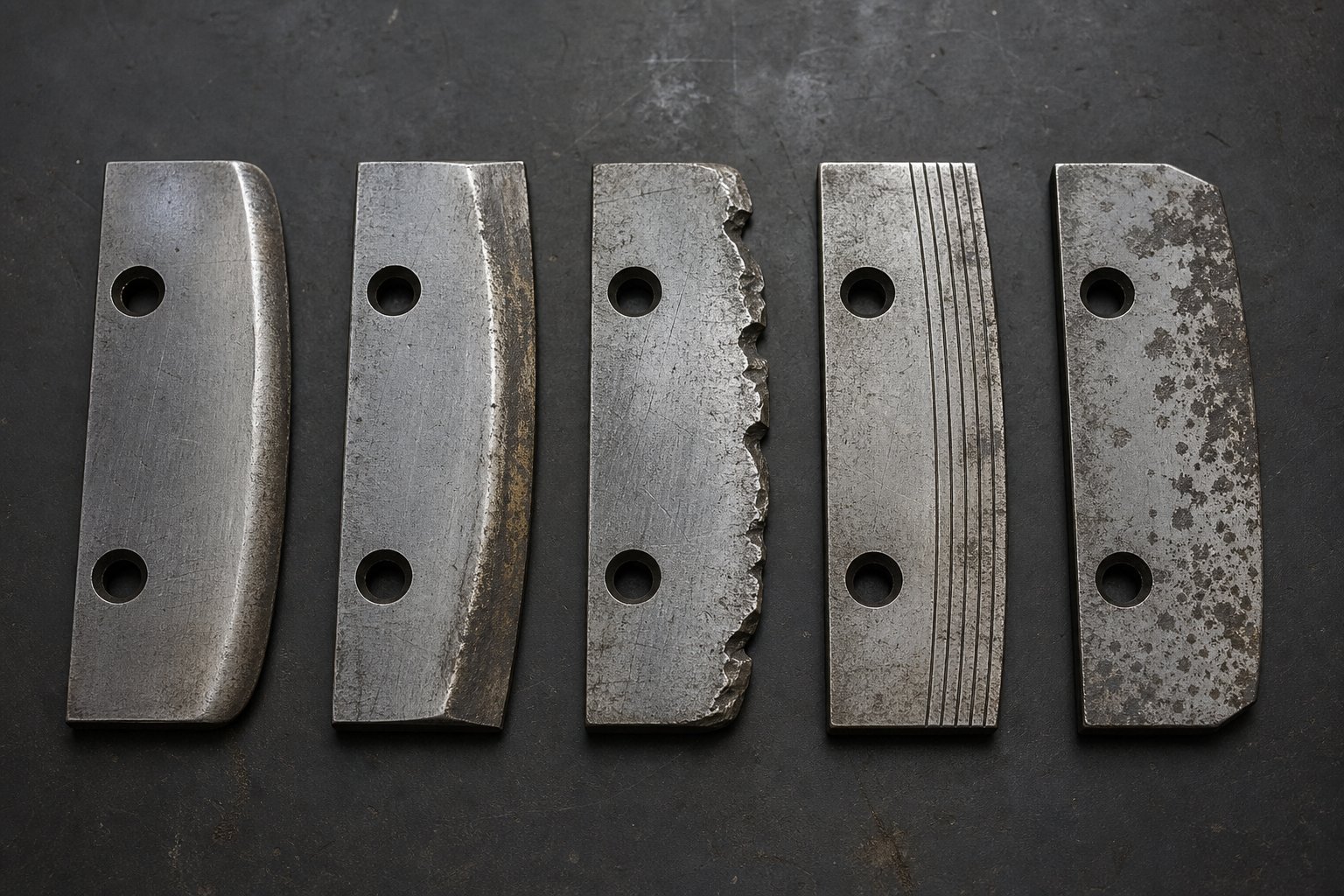
Five distinct wear signatures appear on pelletizing blades across all process types — underwater, strand, water-ring, and hot die-face. Each one points to a different root cause and demands a different corrective response. Here's what to look for:
Uniform edge rounding is the one pattern you actually want to see. When the cutting edge wears evenly across its full length, with a smooth, rounded profile replacing the original sharp edge, it means the rotor is properly aligned, the die plate is flat, and contact pressure is balanced. This is normal, expected wear. The blade simply reached the end of its service life doing exactly what it was designed to do.
One-sided wear — where one end of the blade shows significantly more material loss than the other — tells a different story. This pattern almost always traces back to rotor misalignment or an uneven die plate. When the rotor axis isn't perfectly perpendicular to the die face, one side of each blade presses harder than the other. The result is lopsided wear that gets progressively worse with each operating hour. You might also notice uneven pellet lengths corresponding to the heavy-wear and light-wear zones.
Chipping and micro-fractures along the cutting edge reveal a material mismatch or a mechanical defect at the die face. Why do pelletizing blades chip or fracture? Two main reasons. First, the blade material may be too brittle for the application — imagine running a hard, high-carbide steel on a die plate with surface imperfections that create repeated micro-impacts. Second, die plate defects like raised edges around die holes or debris trapped between the blade and the plate deliver sudden shock loads that exceed the blade's fracture toughness. A groove worn into the die, as American Cutting Edge notes, indicates excessive blade-to-die pressure running over the same area repeatedly — and that groove becomes a launching pad for edge chips on subsequent blade sets.
Grooving or scoring across the blade face — parallel scratches running in the direction of blade travel — is the unmistakable signature of abrasive filler in the polymer stream. Glass fibers, mineral particles, and recycled content containing contaminants all act as micro-abrasives that carve channels into the blade surface. Unlike edge rounding, which is gradual and predictable, scoring accelerates non-linearly: each groove concentrates stress and traps more abrasive particles, deepening the damage with every revolution.
Corrosion pitting appears as clusters of small, irregular craters scattered across the blade surface, particularly on the water-contact side. This pattern shows up in underwater pelletizing systems where process water chemistry isn't properly controlled, or in lines processing corrosive resins like PVC that release acidic byproducts. Pitting weakens the blade structure and creates rough surface zones that increase friction against the die plate, accelerating mechanical wear on top of the chemical attack.
The table below maps each pattern to its root cause and the specific corrective action to take:
| Wear Pattern | Likely Cause | Corrective Action |
|---|---|---|
| Uniform edge rounding | Normal operational wear; correct alignment and pressure | Replace blade at scheduled interval; no process changes needed |
| One-sided wear | Rotor misalignment or uneven die plate surface | Check and correct rotor-to-die alignment; inspect die plate flatness and resurface if needed |
| Chipping or micro-fractures | Blade material too brittle; die plate surface defects; excessive contact pressure | Switch to a tougher blade material (e.g., CPM-9V); inspect and repair die plate; reduce spring pressure |
| Grooving or scoring | Abrasive filler in polymer (glass fiber, minerals, contaminants) | Upgrade to carbide-tipped or CPM-10V blades; verify filler loading is within spec; check for upstream contamination |
| Corrosion pitting | Chemical attack from process water, acidic resin byproducts, or poor water treatment | Switch to corrosion-resistant blade material (440C stainless); improve water chemistry control; inspect and treat water system |
Here's a practical tip: photograph every blade you remove and label it with the date, run hours, polymer processed, and rotor position. Over several blade changes, you'll build a visual library that makes pattern shifts immediately obvious. A blade that used to show clean, uniform rounding but suddenly displays one-sided wear? Something changed — a bearing shifted, a die plate warped, or an alignment bolt loosened. The photos tell you when the problem started.
How Operating Parameters Interact With Blade Longevity
Wear patterns reveal what happened. Operating parameters determine how fast it happens. Every variable in your pelletizer's setup — rotor speed, throughput rate, melt temperature, and cooling water temperature — directly influences how quickly a blade moves from sharp to spent.
Rotor speed is the most intuitive factor. How does rotor speed affect pelletizer blade life? More RPM means more cutting events per hour. A four-blade rotor spinning at 3,000 RPM makes 12,000 cuts per minute. Increase that to 4,000 RPM and you're at 16,000 cuts per minute — a 33% increase in blade-to-die contact events. All else being equal, higher rotor speed shortens blade life proportionally. But rotor speed also affects cut quality: too slow, and the blade can't shear soft melt cleanly, producing smeared or tailed pellets. The sweet spot balances cut quality against acceptable wear rate for your specific polymer and pellet size target.
Throughput rate compounds the speed effect. Higher throughput pushes more polymer through each die hole per unit of time, meaning each blade sweep encounters a thicker strand of material. Thicker strands require more cutting force, increasing the mechanical load on the edge. Running a pelletizer at maximum throughput on an abrasive resin is the fastest way to consume blade life — and one of the most common reasons maintenance teams see blades failing well short of their expected change interval.
Melt temperature plays a subtler but equally important role. Elevated melt temperatures soften the polymer — which should, in theory, make it easier to cut. And it does, to a point. But that same heat transfers into the blade's cutting edge during each contact event. When blade edge temperatures climb above the tempering temperature of the steel (typically 400-550°C for tool steels), the edge begins to soften. You'll notice the pelletizer blade edge rounding causes and fixes change character: instead of slow, abrasive wear, you get rapid edge degradation with a polished, deformed appearance rather than a scratched one. The fix is either reducing melt temperature, if the process allows, or upgrading to a blade material with superior hot hardness — M2 or CPM-M4 instead of D2.
Water temperature in underwater pelletizing systems adds the final variable. The water surrounding the cutting chamber controls how quickly each severed pellet solidifies. Warmer water keeps the polymer softer at the cut point, requiring less cutting force but increasing the risk of pellets sticking together or deforming before they fully solidify. Cooler water accelerates solidification, which means the blade may be cutting material that's already partially rigid — increasing mechanical impact on the edge. Most operators settle on a water temperature window of 50-80°C, but the optimal setting depends on the specific polymer's crystallization behavior. Adjusting water temperature by even 5-10°C can measurably shift blade wear rates and pellet quality simultaneously.
The fastest path to longer blade life isn't buying a harder blade — it's optimizing the operating parameters that control how hard each blade works during every second of its service life.
Recognizing wear patterns and understanding the operating forces behind them gives maintenance teams a diagnostic framework that turns reactive blade changes into proactive process management. But diagnostics alone don't close the loop. The real payoff comes from translating those insights into disciplined lifecycle practices — proper installation, systematic monitoring, and clear decision rules for when to replace versus recondition.
Blade Lifecycle Management From Installation to Replacement
Diagnostics tell you what went wrong. Lifecycle discipline prevents it from happening in the first place. A pelletizing blade's useful life is shaped long before it touches polymer — starting the moment it's bolted onto the rotor. Get installation right, monitor intelligently during production, and make replacement decisions based on data rather than guesswork, and you'll squeeze maximum value from every blade while protecting the expensive die plate beneath it.
Installation and Initial Blade Adjustment
Improper installation is one of the leading causes of premature blade failure — and it's entirely preventable. Knowing how to install pelletizing blades correctly means following a disciplined sequence every single time, regardless of schedule pressure or production urgency.
Start with cleanliness. Before mounting new blades, inspect each blade holder slot and rotor surface for residual polymer, burrs, or debris. Even a small particle trapped beneath a blade throws off its seating, creating a high spot that concentrates die-plate contact on one station while leaving others too light. Use a lint-free cloth and, if needed, a brass scraper to ensure every mounting surface is perfectly clean.
Next, seat each blade and torque the retaining fasteners to the manufacturer's specification — typically using a calibrated torque wrench and following a crisscross tightening pattern to distribute clamping force evenly. Over-torquing distorts the blade body; under-torquing allows micro-movement during operation that leads to fretting wear and fastener loosening.
Height uniformity across all blade stations is non-negotiable. Every cutting edge must sit at the same radial height so that all stations contact the die face equally. Use adjustment screws or precision shims to bring each blade into spec — variations of even 0.001 inches create the alternating long-short pellet patterns discussed earlier. Some maintenance teams use a dial indicator or feeler gauges against the die plate face to verify uniformity before closing the cutting chamber.
Set the initial contact pressure according to the pelletizer manufacturer's guidelines. For spring-loaded systems, this means adjusting spring compression to the specified preload. For hydraulic systems, set the forward-thrust pressure to the recommended startup value — typically the low end of the operating range.
Finally, run a break-in period. Start the pelletizer at reduced throughput for the first 15-30 minutes, allowing the fresh blade edges to seat and conform against the die plate under light load. Jumping immediately to full production with brand-new blades risks edge micro-chipping from aggressive initial contact. Think of it like breaking in a new set of brake pads — gentle at first, then build to full performance.
In-Service Monitoring and Replacement Timing
Once blades are running, the question becomes: when do you change them? Too early wastes usable blade life. Too late risks pellet quality, die plate scoring, and the kind of cascading damage that turns a routine blade swap into an expensive rebuild. Pelletizer blade change interval best practices rely on three monitoring inputs working together:
- Motor amperage trends: A sudden increase in motor amperage signals dull blades or a blockage demanding immediate attention. A gradual upward drift over days or weeks tracks normal wear progression — and tells you when the edge has degraded enough to increase cutting resistance beyond acceptable levels.
- Pellet quality checks: Visual inspection of pellet samples at regular intervals catches tails, fines, and dimensional variation early. Once you see quality slipping, the blade edge is already past its prime.
- Visual inspection during scheduled shutdowns: Pull the cutting chamber open and examine blade edges directly. Look for the wear patterns covered in the previous section — uniform rounding is normal; chipping, scoring, or one-sided wear demands investigation before installing the next set.
The tradeoff is real. Pushing blade life to the absolute limit saves on blade inventory costs but risks degrading pellet quality in the final hours of service — and a blade that's worn past its edge radius can score the die plate, creating permanent damage that outlasts any single blade set. Proactive replacement, timed to a data-driven interval, almost always delivers lower total cost than reactive changes triggered by quality failures or mechanical alarms.
When it's time to swap, follow this pelletizer blade replacement procedure step by step:
- Lockout/tagout: De-energize the pelletizer completely and apply LOTO devices to all energy sources. Verify zero-energy state before proceeding.
- Access the rotor: Open or remove the cutting chamber housing per the machine's service procedure. Allow components to cool if the system was recently running.
- Remove old blades: Loosen retaining fasteners evenly and extract each blade. Place used blades in a labeled container — note the run hours, polymer processed, and any visible wear anomalies for your diagnostic records.
- Inspect holders and rotor surfaces: Check each blade slot for scoring, debris, or thread damage. Inspect the rotor body for cracks, corrosion, or fretting marks. Address any issues before installing new blades.
- Install new blades: Seat each blade, torque fasteners to specification, and verify height uniformity across all stations using gauges or indicators.
- Set blade-to-die gap and contact pressure: Adjust spring preload or hydraulic pressure to the manufacturer's startup specification. Verify uniform contact across the die face.
- Startup verification: Remove LOTO devices, close the chamber, and restart at reduced throughput. Inspect initial pellet quality, listen for abnormal sounds, and monitor amperage. Ramp to full production only after confirming clean, consistent cuts.
Reconditioning Versus Replacement
Can pelletizing blades be resharpened? In most cases, yes — and reconditioning represents a legitimate strategy for extending total blade value. Precision rotor sharpening services analyze each blade's geometry, remove only the minimum material necessary to restore a sharp, flat edge, and return the blade to like-new cutting performance.
The key word is precision. Resharpening on a poorly calibrated surface grinder — or worse, by hand — introduces flatness errors and dimensional inconsistencies that cause the same problems as a worn blade. Each grinding pass removes material from the blade's cutting face, reducing overall blade thickness. After multiple resharpenings, the blade becomes too thin to maintain proper rigidity and die-plate contact. At that point, replacement is the only option.
A practical approach: establish a maximum number of resharpening cycles for each blade type based on the material thickness tolerance specified by the pelletizer manufacturer. Track each blade through its reconditioning history. And when a rotor is sent for resharpening, have the service partner inspect for operational issues — uneven wear across stations, for example — that might signal alignment or die-plate problems worth correcting before the next production run.
Skipping a scheduled resharpening to save money often costs more in the long run — over-worn blades require deeper material removal to restore geometry, shortening total blade life and accelerating the need for full replacement.
Lifecycle management isn't glamorous work. It doesn't appear on dashboards or impress visitors during plant tours. But for the maintenance teams who practice it consistently, the payoff is tangible: longer intervals between changes, fewer quality excursions, and a die plate that stays flat and productive far longer than it otherwise would. The remaining question — whether all this discipline translates into actual cost savings — comes down to how you think about blade economics.
Economics of Blade Selection and Smart Sourcing Strategies
A procurement spreadsheet can be a dangerous thing. When blade purchases show up as a single line item — quantity times unit price — the cheapest option always wins. And that's exactly how plants end up spending more, not less, on their pelletizing operation. The pelletizing blade cost versus blade life comparison rarely favors the lowest-price option once you account for everything that surrounds each blade change: the labor, the downtime, the scrap, and the die plate damage that accumulates when marginal blades wear too fast.
Thinking clearly about economics means zooming out from the purchase order and looking at the full cost picture — and then applying that same rigor to where and how you source replacement blades.
Total Cost of Ownership Thinking for Blade Procurement
Imagine two blades sitting side by side on a maintenance bench. Blade A costs $45. Blade B costs $110. If your purchasing department evaluates them on unit price alone, Blade A wins every time. But what if Blade A lasts 120 hours before pellet quality degrades, while Blade B runs 400 hours with cleaner cuts and fewer rejects? Suddenly, the math flips completely.
The pelletizing blade total cost of ownership calculation captures what unit price ignores. Here's the formula that makes the real economics visible:
Total Cost per Hour = (Blade Purchase Price + Installation Labor + Downtime Cost per Change + Scrap and Quality Cost) / Hours of Productive Runtime
Each variable matters more than you might expect:
- Blade purchase price: The obvious starting point, but typically the smallest contributor to total cost in high-throughput operations.
- Installation labor: Every blade change requires a trained technician to perform lockout/tagout, open the cutting chamber, remove and inspect old blades, install new ones, set contact pressure, and verify startup quality. That's 30 minutes to two hours of skilled labor per change — multiplied by your fully burdened labor rate.
- Downtime cost per change: While the pelletizer is down for blade work, the entire extrusion line either stops or diverts production. For a line producing 2,000-5,000 kg/hour of compound, every hour of downtime carries a significant opportunity cost. Industry estimates suggest that factoring in lost revenue and delayed orders, premium blades that reduce changeover frequency can save operations tens of thousands of dollars annually.
- Scrap and quality cost: A blade approaching end-of-life doesn't fail all at once. It degrades gradually — producing increasingly tailed, oversized, or dusty pellets during its final hours of service. That marginal material either gets reclassified, reprocessed, or scrapped. If it reaches a customer, the cost includes complaints, returns, and credibility damage that no spreadsheet captures.
Let's run a simplified comparison to see how this plays out in practice:
| Cost Factor | Blade A (Standard D2) | Blade B (CPM-10V Upgrade) |
|---|---|---|
| Unit price (per blade set) | $180 | $440 |
| Average service life (hours) | 160 | 420 |
| Blade changes per 5,000-hour year | ~31 | ~12 |
| Installation labor per change ($75/hr x 1 hr) | $2,325 | $900 |
| Downtime cost per change ($500/hr x 1 hr) | $15,500 | $6,000 |
| Annual blade purchase cost | $5,580 | $5,280 |
| Estimated annual scrap/quality cost | $4,000 | $1,200 |
| Total annual cost | $27,405 | $13,380 |
The numbers speak for themselves. Blade B costs 2.4 times more per set — and saves over $14,000 per year. The annual blade purchase cost is nearly identical between the two options. All the savings come from fewer changeovers, less downtime, and reduced scrap. This is the pelletizer blade cost versus blade life comparison that purchasing departments rarely see unless maintenance teams build the case.
Material upgrades drive the biggest leverage. Moving from D2 to CPM-10V on an abrasive glass-filled compound line doesn't just add hours — it can triple service intervals while producing cleaner pellets throughout the entire run. Stepping up to tungsten carbide tips on highly filled feedstocks pushes that multiplier even further. The upfront investment looks steep until you divide it by the thousands of additional productive hours it delivers.
Even within the same material grade, quality of execution matters. Two D2 blades from different suppliers can deliver wildly different service lives based on steel purity, heat treatment precision, and grinding accuracy. A blade hardened to HRC 58 instead of the target HRC 61 wears measurably faster. One ground with a surface finish of 16 Ra instead of 8 Ra creates more friction against the die plate. These "invisible" quality differences only reveal themselves in runtime performance — which is exactly why sourcing strategy matters as much as material selection.
Cross-Brand Compatibility and OEM-Equivalent Sourcing
Here's something many plant buyers discover only after years of paying OEM prices: pelletizing blades are not proprietary magic. They're precision-machined steel components defined by measurable dimensions, material grades, hardness specifications, and surface finish requirements. Any qualified manufacturer with the right equipment and metallurgical expertise can produce OEM equivalent pelletizer blades for Gala and Nordson systems — or for EREMA, NGR, Coperion, Maag, and virtually any other major pelletizer brand — from engineering drawings, physical samples, or even measured dimensions taken from existing blades.
This matters because captive OEM supply chains often come with premium pricing, extended lead times, and limited flexibility. When your pelletizer goes down at 2 AM and the OEM quotes six weeks for replacement blades, having an alternative source isn't a luxury — it's an operational necessity. How to source aftermarket pelletizing blades effectively comes down to verifying that the alternative supplier can match or exceed the original specifications across every parameter that affects performance.
When evaluating alternative blade suppliers, insist on verification across these critical factors:
- Material certification: The supplier should provide mill certificates or equivalent documentation confirming the exact steel grade, chemical composition, and material origin. Vague claims of "premium steel" without traceability are a red flag — as industrial blade sourcing guides consistently emphasize, asking for material certificates and test results before purchase is essential to avoiding substandard components.
- Dimensional tolerances: Blade length, width, thickness, mounting hole positions, and edge geometry must match OEM specifications within the tolerance bands required for proper fit. Even 0.002 inches of deviation on blade thickness can affect seating in the holder and contact uniformity against the die plate.
- Hardness verification: Request Rockwell C hardness test results — not just a stated range, but actual measured values from production samples. Consistent hardness within the target window (typically HRC 58-64 depending on grade) confirms proper heat treatment execution.
- Surface finish quality: The cutting face and die-contact surface should meet specified Ra values. A rough surface finish increases friction, accelerates wear, and can score the die plate — negating any cost advantage the alternative blade offered.
- Lead time reliability: A supplier who quotes fast delivery but ships late creates the same downtime risk as not having a backup source at all. Evaluate actual delivery performance, not just promised timelines.
Suppliers who manufacture from customer-provided drawings, samples, photos, or measured dimensions offer the greatest flexibility for plants running older or less common pelletizer models where standard catalog parts don't exist. This capability is particularly valuable for machine rebuilders who source parts across multiple brands and vintages.
NANHAIYA, for example, manufactures OEM-equivalent pelletizing blades alongside a full range of extruder spare parts — including die heads, screen packs, screw tips, heater bands, and thermocouples — all produced to specification from drawings, samples, or measured dimensions. For maintenance teams managing full pelletizer rebuilds or stocking spares across multiple machine brands, working with a single-source partner who covers blades and complementary components streamlines procurement and reduces the number of vendor relationships to manage.
The broader point applies regardless of which supplier you choose: don't let brand loyalty or procurement inertia lock you into a single source that no longer serves your operational needs. Validate quality rigorously, demand documentation, and let total cost of ownership — not unit price or brand name — drive your blade sourcing decisions. The economics consistently reward plants that approach pelletizing blade procurement as an engineering decision rather than a purchasing transaction.
With the right blade material matched to your process, a reliable supply chain behind it, and the total cost framework guiding every purchase decision, the final step is pulling all of these principles together into a practical operating philosophy — one that keeps pellet quality high and unplanned downtime low across every production run.
Putting It All Together for Reliable Pellet Production
Pelletizing blade performance isn't determined by any single decision. It's the cumulative result of dozens of choices — material grade, process matching, installation discipline, contact pressure management, operating parameter tuning, and replacement timing — all working together or all undermining each other. Miss one link in the chain and the whole system tells you about it, loud and clear, through tailed pellets, rising amperage, or chipped edges that show up at the worst possible moment.
Key Principles for Pelletizing Blade Excellence
Pelletizing blade performance is a system-level outcome determined by material selection, process matching, die plate condition, operating parameters, and maintenance discipline — not any single factor in isolation.
That single idea is worth internalizing. Here's how to choose the right pelletizing blade for your process and keep it performing at its best — distilled into the critical decision points covered throughout this article:
- Match blade material to your polymer and filler profile. D2 handles unfilled polyolefins reliably. Glass-filled or mineral-loaded compounds demand CPM-10V or carbide. Corrosive environments like underwater PVC lines need stainless grades. Don't guess — let the resin dictate the steel.
- Maintain the blade-to-die-plate interface rigorously. Inspect die plate flatness at every blade change. Resurface when deviation exceeds 0.001-0.002 inches. A perfect blade on a worn die plate is wasted money.
- Establish data-driven replacement intervals. Track amperage trends, pellet quality checks, and visual wear patterns. Build a pelletizer blade maintenance checklist for plant teams that turns subjective judgment into repeatable, documented decisions.
- Think in total cost of ownership terms. Divide total costs — purchase price, labor, downtime, scrap — by productive runtime hours. The cheapest blade per unit is almost never the cheapest blade per hour of clean production.
- Photograph and document every blade you remove. Over time, this visual record reveals process drift, alignment shifts, and material issues that no single inspection catches on its own.
Building a Reliable Spare Parts Supply Chain
Even the best maintenance program collapses without parts on the shelf when you need them. Unplanned downtime rarely results from exotic failures — it comes from not having a replacement blade, a spare screen pack, or a backup heater band available when the clock is ticking. A single source supplier for pelletizer spare parts dramatically simplifies this challenge.
The practical recommendation: establish a relationship with a supplier who can manufacture to your specific machine requirements — from drawings, physical samples, or measured dimensions — across the full range of components your pelletizer and extruder line requires. That includes not just blades but die heads, thermocouples, heater bands, screw tips, and gearbox components. When one partner covers the complete bill of materials, lead times shrink, quality stays consistent, and your maintenance team spends less time managing vendor relationships and more time keeping lines running.
NANHAIYA's extruder spare parts program is built around exactly this model — producing OEM-equivalent pelletizing blades and complementary extruder components to specification from customer-provided drawings, samples, photos, or dimensions. For plant buyers and machine rebuilders sourcing across multiple brands and machine vintages, that kind of manufacturing flexibility turns a fragmented spare parts strategy into a streamlined one.
Your pelletizing blade is always talking. The tails, the dust, the wear patterns, the amperage spikes — every signal carries actionable information. The plants that listen, document, and respond with disciplined material selection, interface management, and smart sourcing are the ones that run longer, produce cleaner pellets, and spend less doing it. That's not theory. That's the math.
Frequently Asked Questions About Pelletizing Blades
1. What is a pelletizing blade and what does it do?
A pelletizing blade is a precision-ground cutting tool mounted on a high-speed rotor inside a pelletizer head. It shears molten or cooled polymer strands against a die plate face to produce uniform plastic pellets. The blade's edge geometry, hardness, and mounting accuracy directly control pellet shape, size consistency, and surface finish. Poor blade condition leads to defects like tails, doubles, angel hair, and fines that cause feeding problems in downstream processes such as injection molding and film extrusion.
2. How long do pelletizing blades last and when should they be replaced?
Blade life varies widely depending on the polymer being processed, filler content, rotor speed, and blade material. Standard D2 tool steel blades running unfilled polyolefins may last several hundred hours, while the same blades on glass-filled nylon could wear out in days. CPM-10V or carbide upgrades can extend life by two to three times on abrasive compounds. The best replacement timing relies on monitoring motor amperage trends, inspecting pellet quality at regular intervals, and examining blade edges during scheduled shutdowns rather than waiting for quality failures.
3. What is the best blade material for pelletizing glass-filled or mineral-filled polymers?
For highly abrasive glass-filled or mineral-filled resins, tungsten carbide-tipped blades or CPM-10V powder metallurgy steel blades deliver the longest service life. Carbide offers extreme wear resistance but is brittle under impact or misalignment. CPM-10V provides wear resistance approaching carbide levels while maintaining significantly better toughness, making it ideal for lines where die plate conditions or intermittent impacts are a concern. Standard D2 tool steel wears too rapidly on abrasive compounds and typically requires frequent changeovers that drive up total operating cost.
4. Can pelletizing blades be resharpened instead of replaced?
Yes, most pelletizing blades can be resharpened using precision surface grinding to restore a flat, sharp cutting edge. However, each resharpening cycle removes material and reduces overall blade thickness. After multiple regrinds, the blade becomes too thin to maintain proper rigidity and die plate contact, at which point full replacement is necessary. It is critical that resharpening be performed on calibrated equipment by experienced technicians, since imprecise grinding introduces flatness errors that cause uneven die contact and accelerate both blade and die plate wear.
5. Where can I source OEM-equivalent pelletizing blades for brands like Gala, Nordson, or Maag?
OEM-equivalent pelletizing blades can be manufactured by qualified aftermarket suppliers who produce parts to original specifications from engineering drawings, physical samples, or measured dimensions. When evaluating suppliers, verify material certification with mill certificates, confirm dimensional tolerances match OEM specs, request Rockwell hardness test results from production samples, and assess surface finish quality. Suppliers like NANHAIYA (nhyscrew.com) manufacture pelletizing blades alongside complementary extruder spare parts such as die heads, screen packs, and screw tips, offering a single-source solution for maintenance teams managing multiple pelletizer brands.
Written by
Nanhaiya Technical Team
Zhoushan Nanhaiya Plastic Machinery Co., Ltd.
The Nanhaiya technical team supports screw and barrel manufacturing projects through application review, technical communication, custom manufacturing coordination, and production and quality control.
Discuss Your Application
Related Articles
More insights on screw barrel technology and plastics processing.

What Nobody Tells You About Screw Barrel For Plastic Machine Design
Oct 10, 2026
Learn how screw barrel for plastic machine design affects melt quality, throughput, and wear life. Covers geometry, resin matching, troubleshooting, and sourcing.
Read Article
Single Screw Extruder for Sheet: Stop Guessing, Start Specifying
Oct 9, 2026
Learn how to specify a single screw extruder for sheet production. Covers screw geometry, resin-specific processing, troubleshooting, and maintenance best practices.
Read Article
PE Pipe Extruder Machine: What Datasheets Won't Tell You
Oct 9, 2026
Learn how a PE pipe extruder machine works, key specs explained, material grade selection, maintenance tips, and buyer guidance beyond the datasheet.
Read ArticleLooking for something else?
Search by material, symptom or product and jump straight to the relevant page.
These are navigation suggestions based on keyword matching — not a quotation, not a delivery commitment, and not a substitute for engineering review. Final specification is confirmed by our engineers against your drawings and processed material.
Need help with screw barrel selection?
Share your machine model, processed material and application. Our team can help with pricing and technical support.